PBY Catalina (Vintage Plans) Build Thread


 01-20-2019, 05:45 PM
#27

Thread Starter
Join Date: Nov 2005
Location: fort collins,
CO
Posts: 448
Likes: 0
Received 0 Likes
on
0 Posts
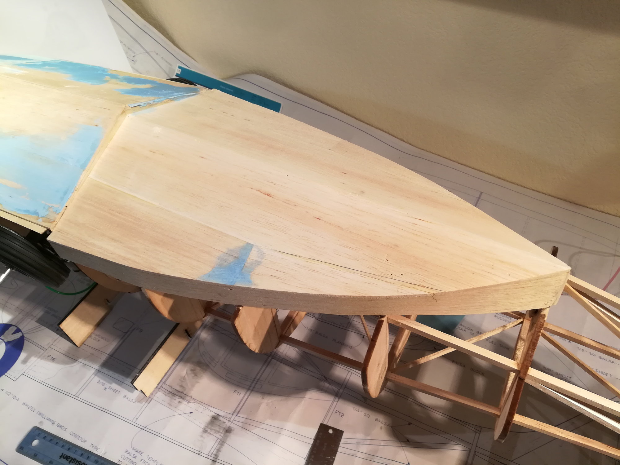
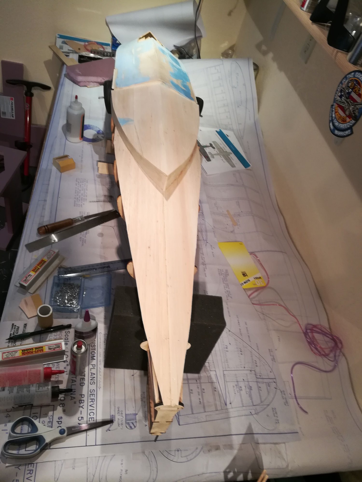
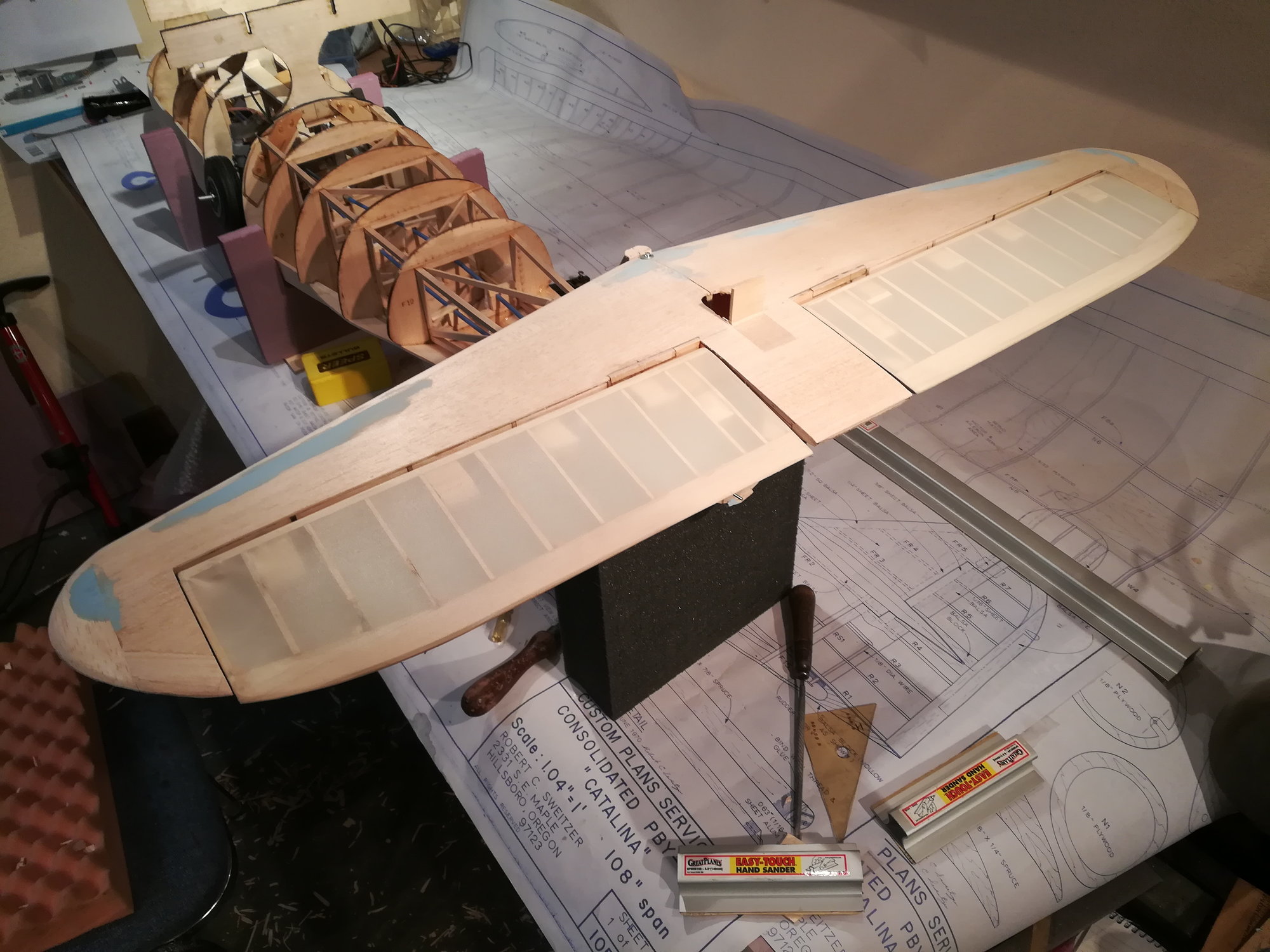
Finished sheeting the bottom of the fuse (the hull that rides in the water and the tail boom. To sheet the bottom of the tail boom, I first made a template out of cardboard. The rest of the fuse is much too curved in its shape to be sheeted, so will have to plank it. I hate planking 
 01-21-2019, 08:10 PM
#29
Thread Starter
Join Date: Nov 2005
Location: fort collins,
CO
Posts: 448
Likes: 0
Received 0 Likes
on
0 Posts
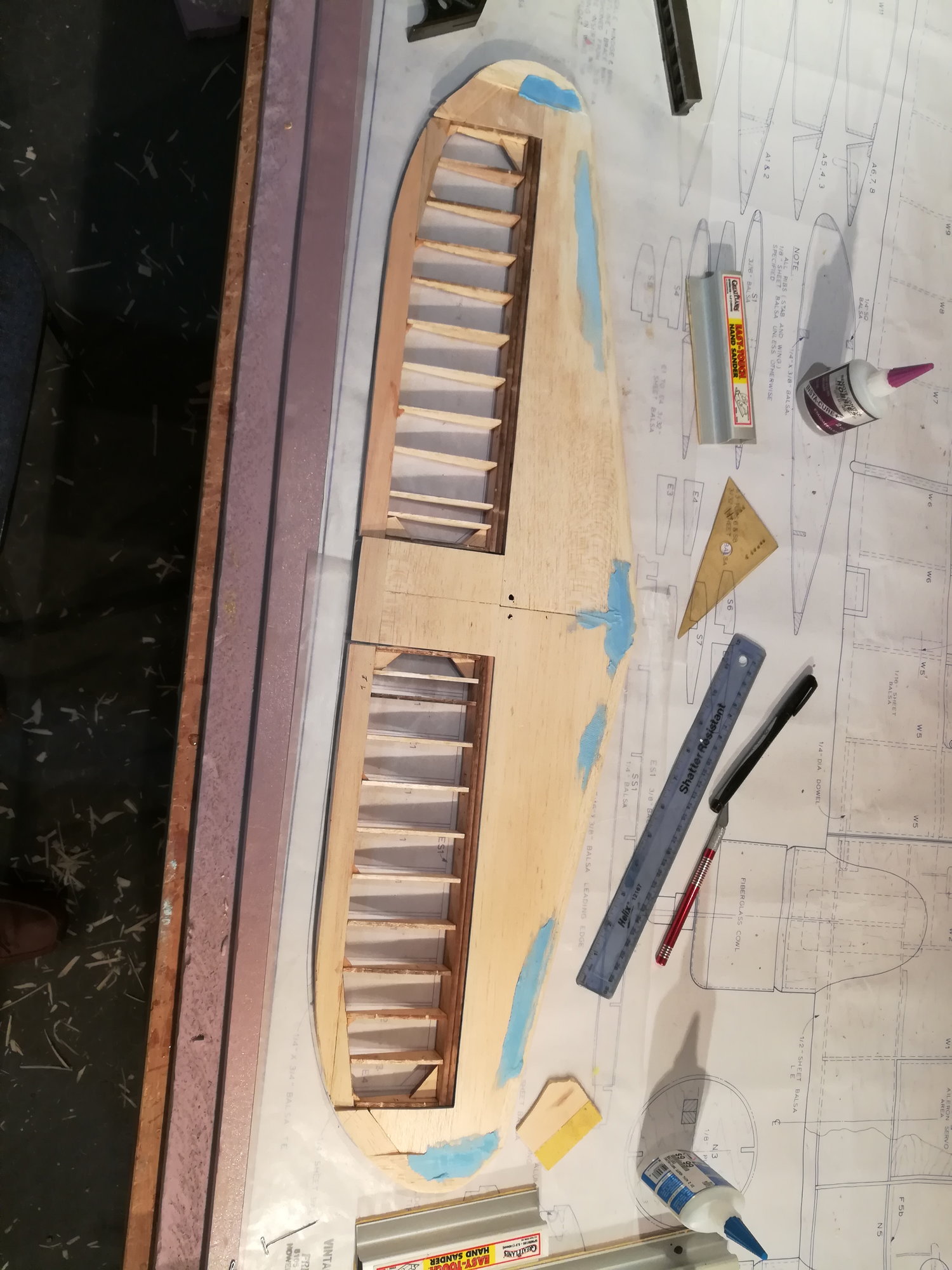
Finished the balsa blocks around the stab. Did some fill and sanding. Built the elevators and started sanding to shape. Right elevator is hinged and you can see the hinge mounting blocks in both elevators.
 01-27-2019, 06:20 PM
#32
Thread Starter
Join Date: Nov 2005
Location: fort collins,
CO
Posts: 448
Likes: 0
Received 0 Likes
on
0 Posts
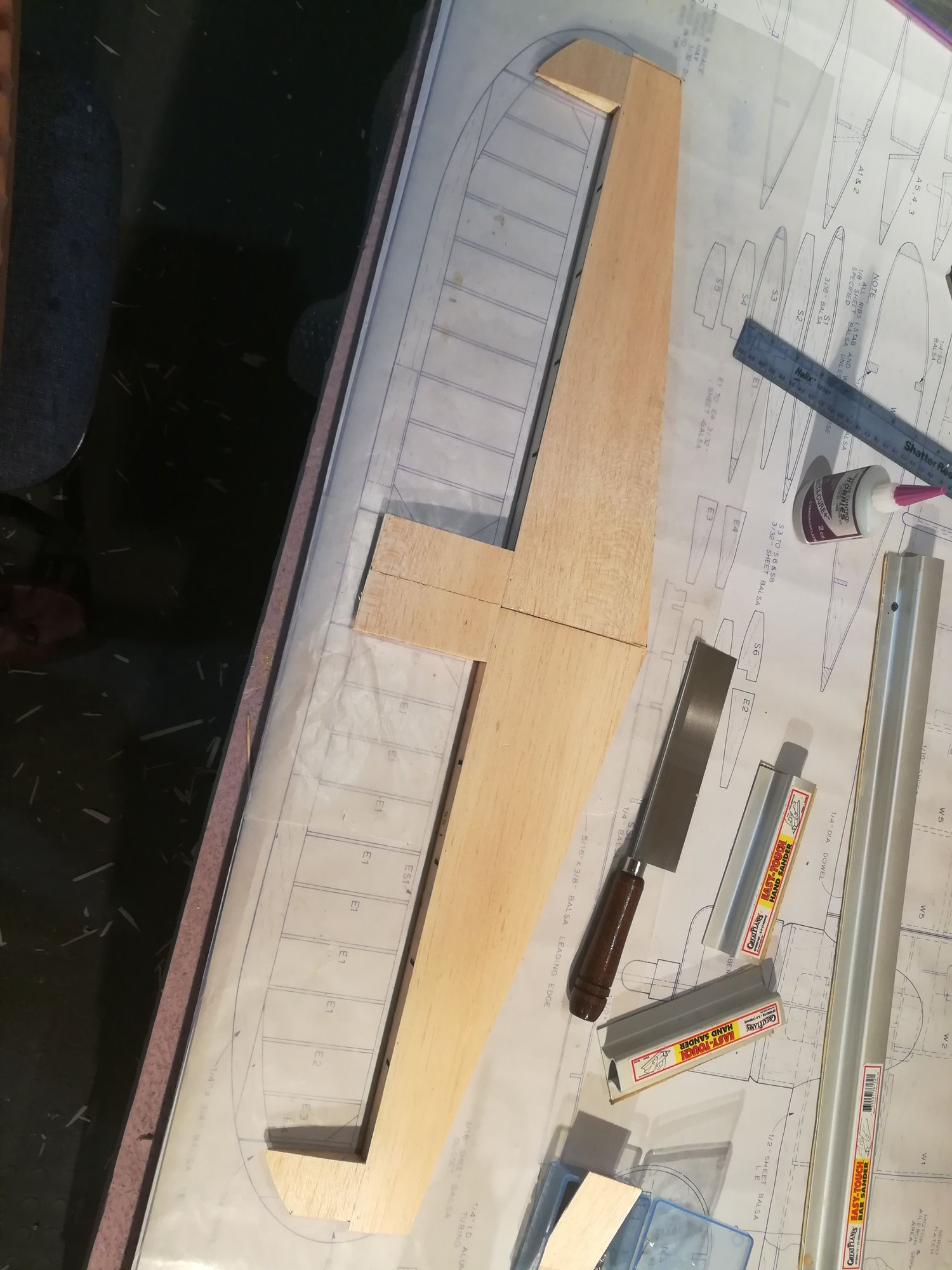
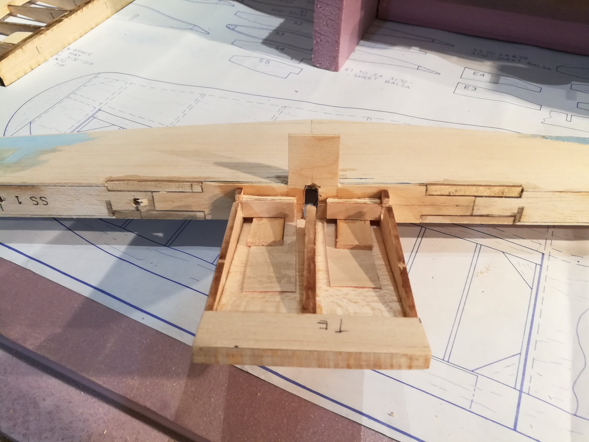
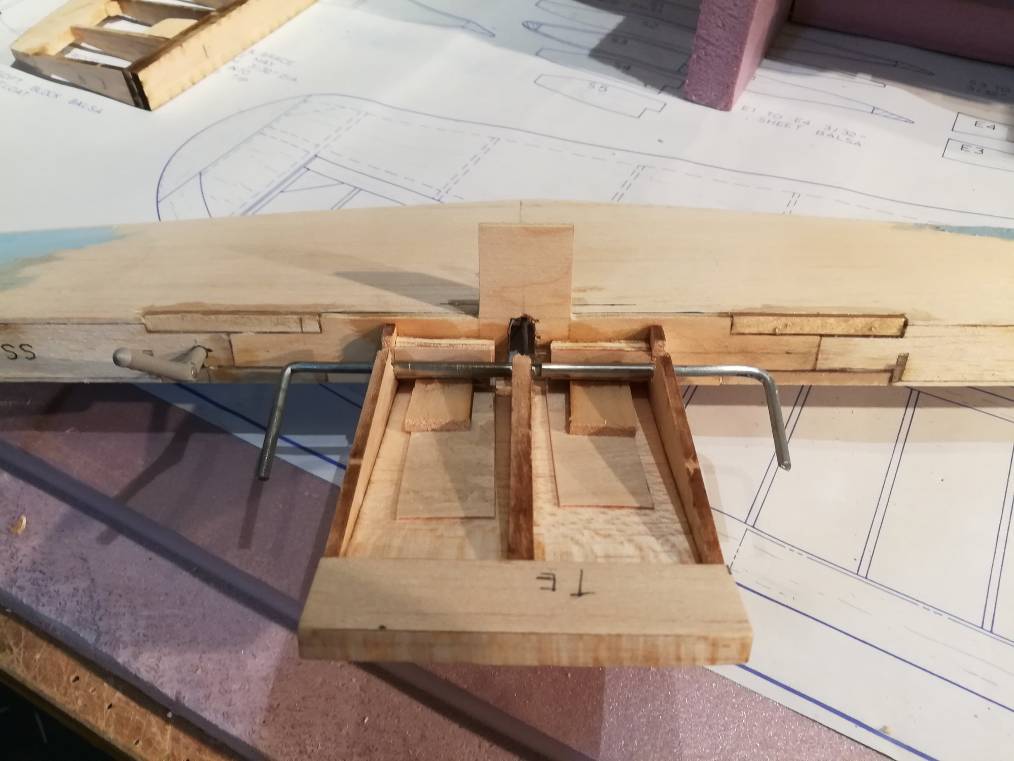
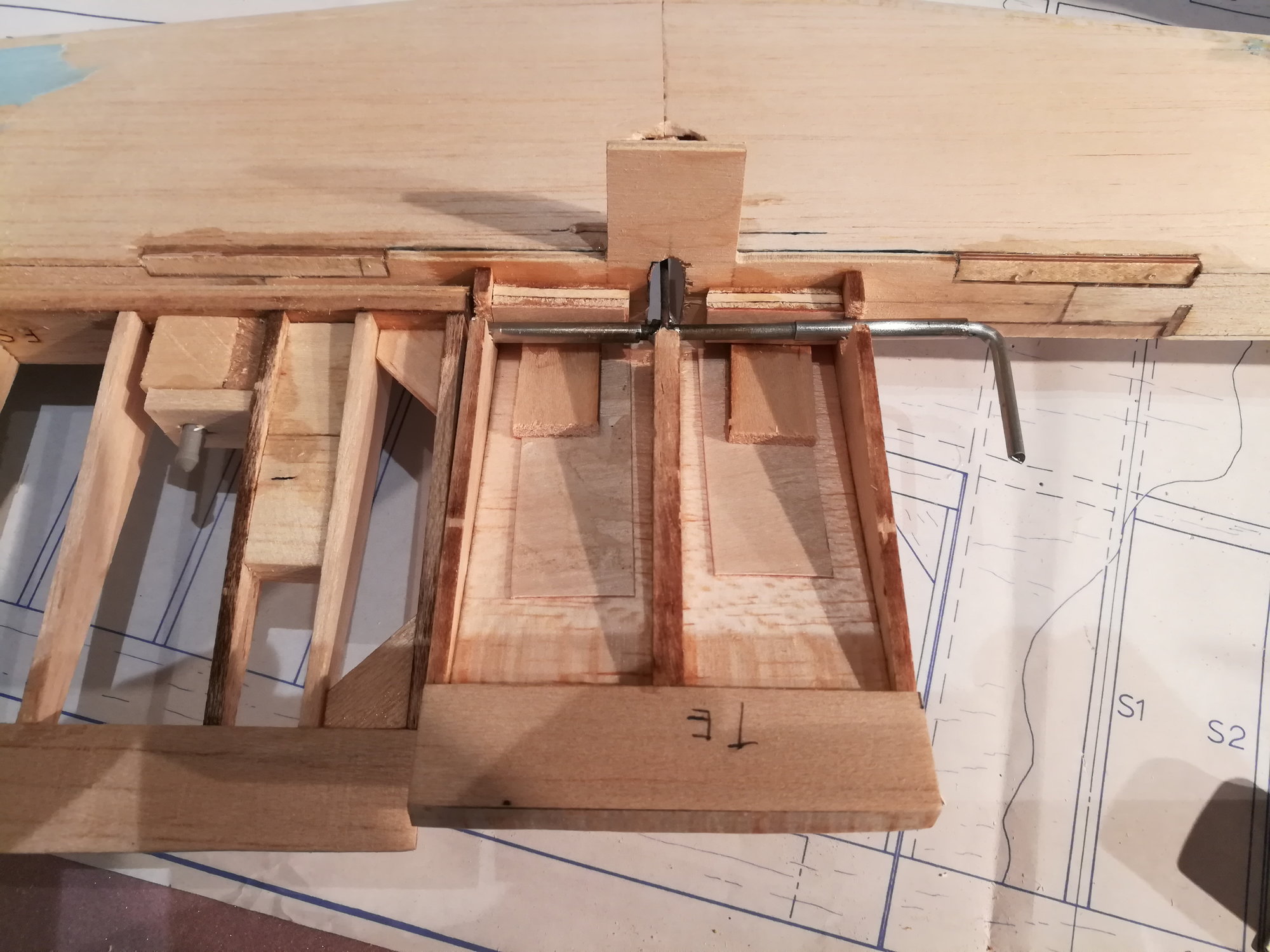
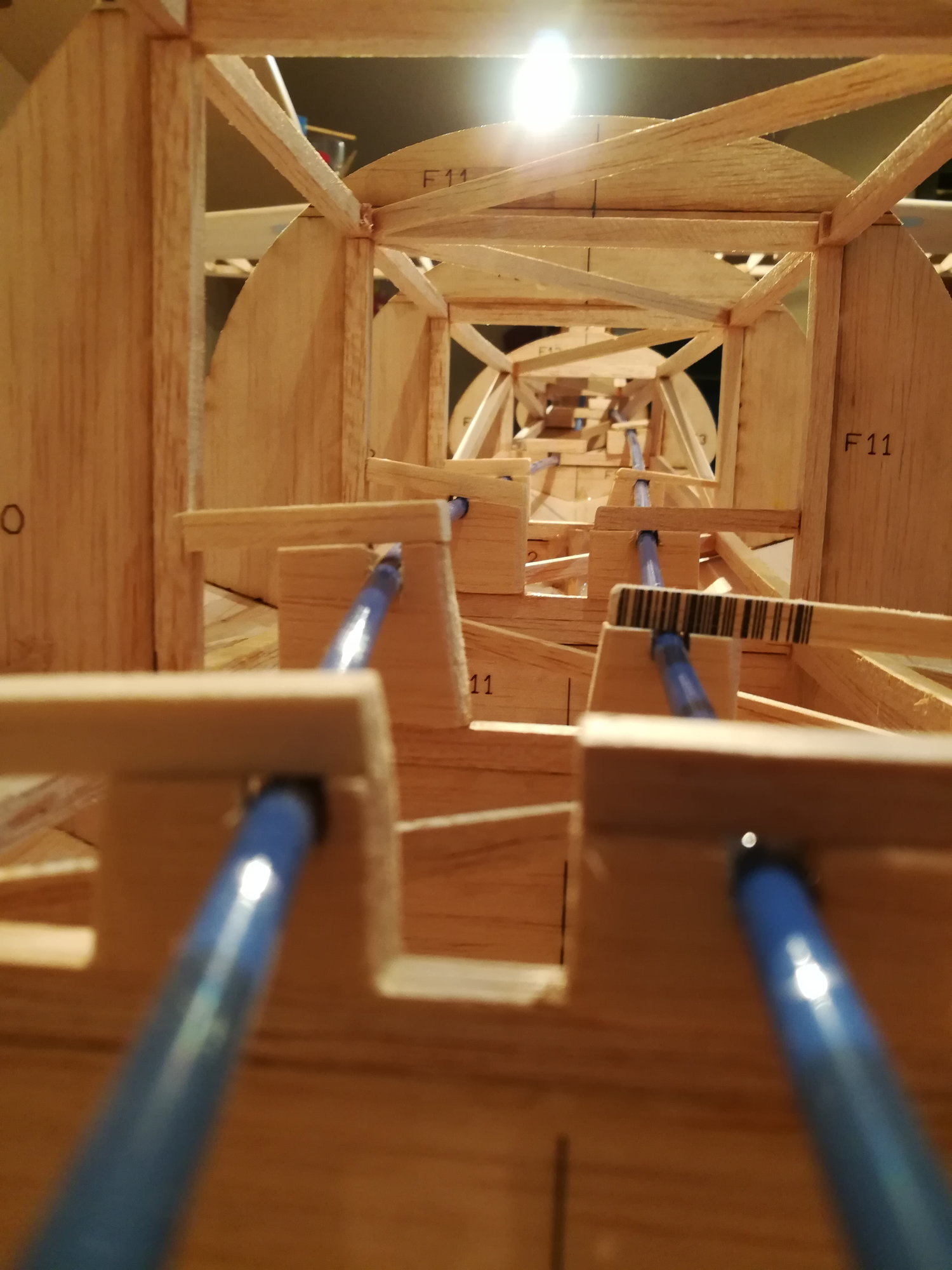
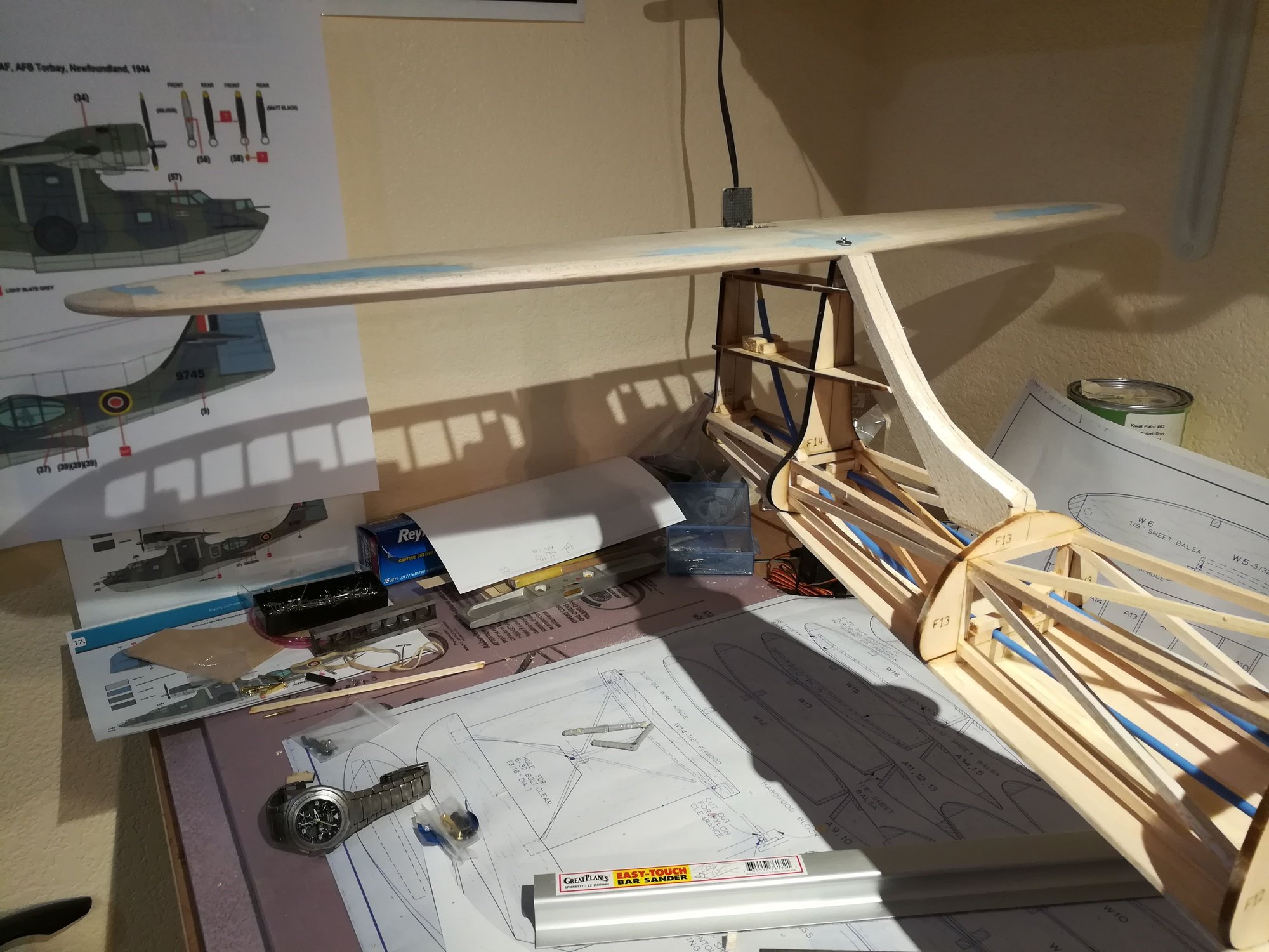
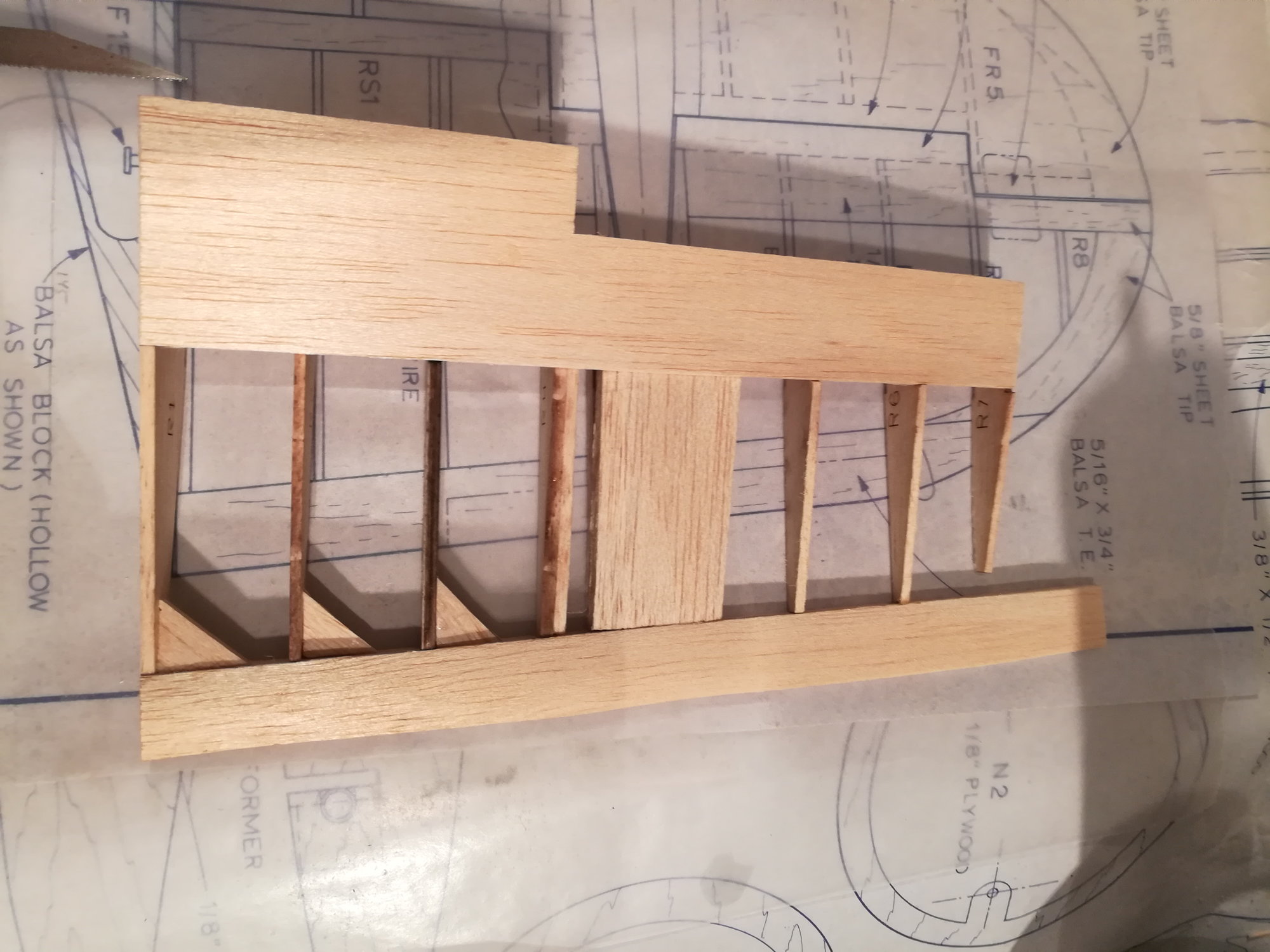
The PBY presents an interesting opportunity for elevator control. The elevator pivot line is in the rudder (not vert stabilizer). This limits how to control it. The plans offer no suggestion for operating the elevator. If you put the hinge line against the horizontal stab this would be easier. But I want scale movement of all the control surfaces.To accomplish this, the only way is to have the elevator control routed into the horizontal stab. Unfortunately this will have to go through the h-stab spar, which will have to be cut in half! 
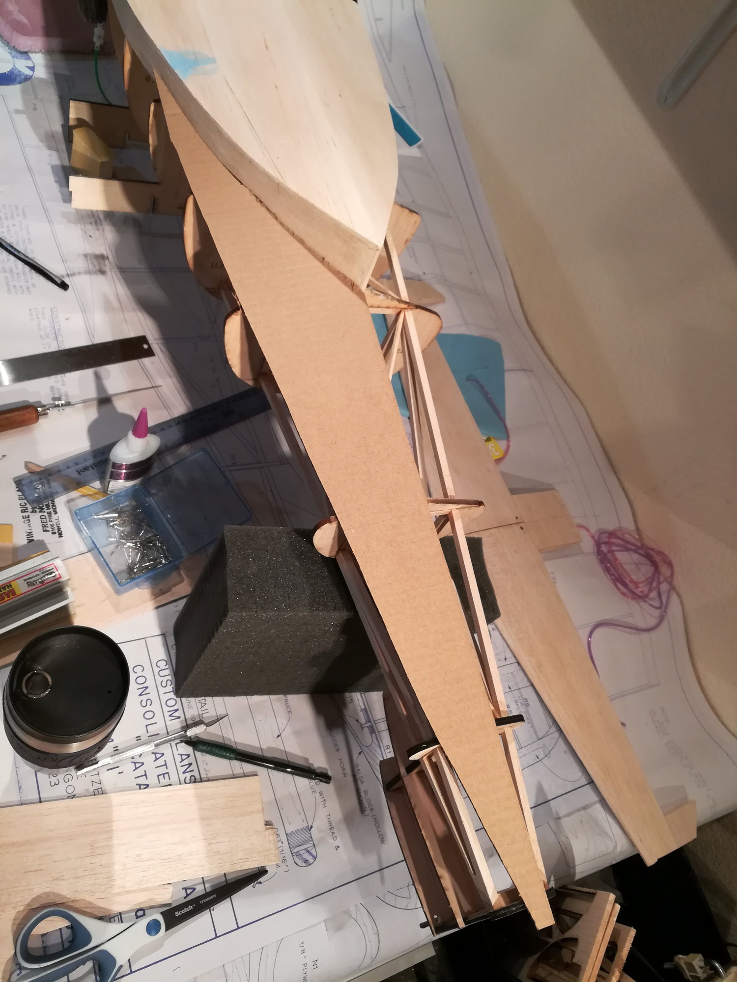
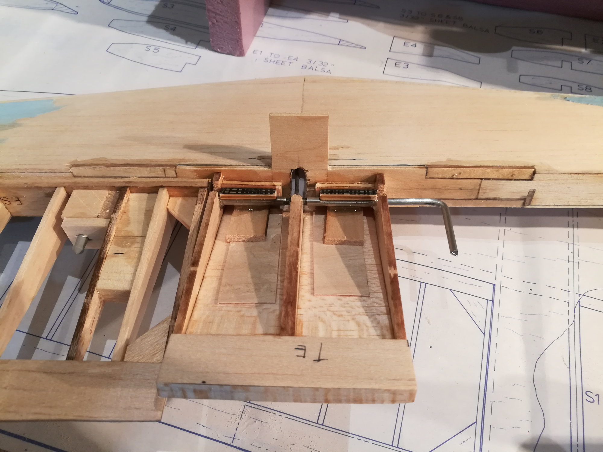
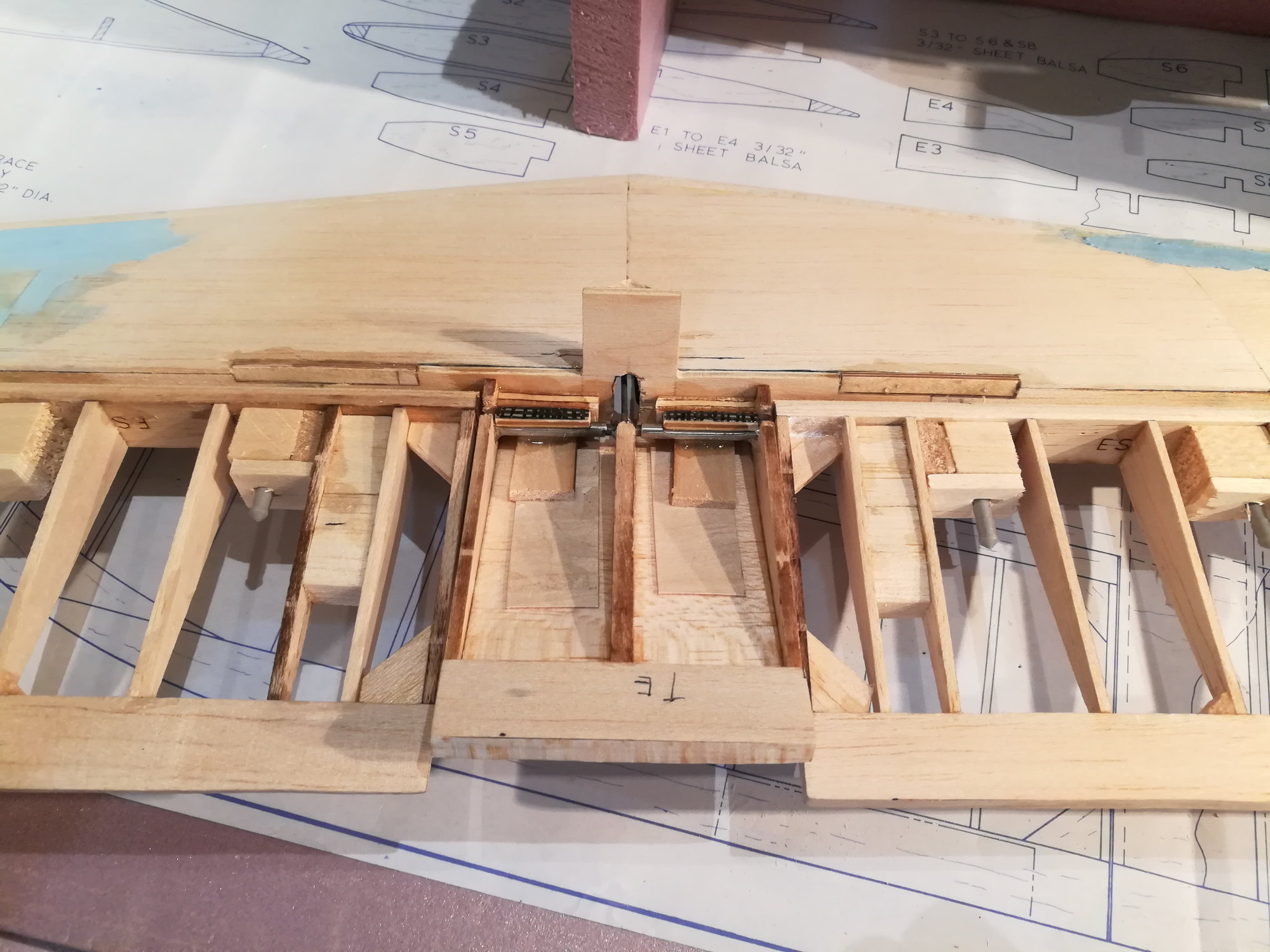
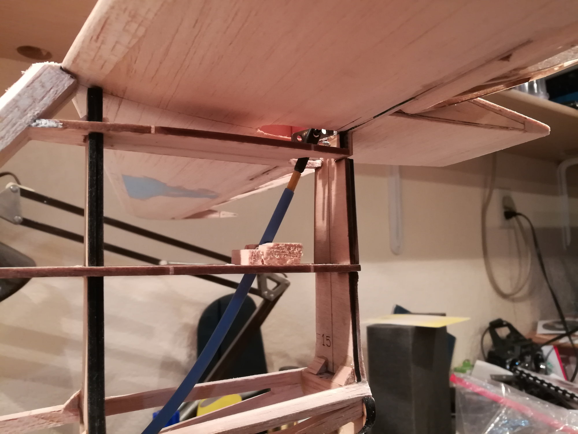
To support the elevator control, the spar will need to be modified with an opening 1/4" wide running top to bottom of the spar. Obviously this will destroy the spar's primary function. The only space to reinforce the spar is inside the v-stab. A plate of ply and carbon fiber in will be used to carry loads around the opening. The spar will be cut to allow the plate to be recessed into the spar and to fit in the original space. Here's a couple of picts. The CF is facing forward in the second picture.
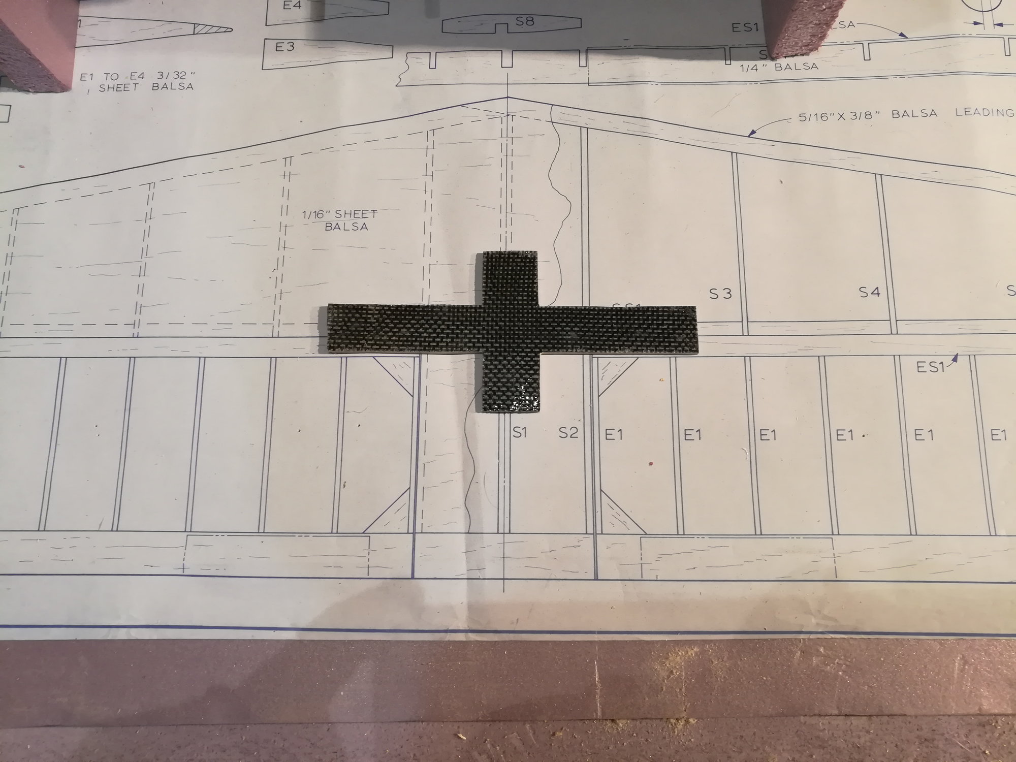

To support the elevator control, the spar will need to be modified with an opening 1/4" wide running top to bottom of the spar. Obviously this will destroy the spar's primary function. The only space to reinforce the spar is inside the v-stab. A plate of ply and carbon fiber in will be used to carry loads around the opening. The spar will be cut to allow the plate to be recessed into the spar and to fit in the original space. Here's a couple of picts. The CF is facing forward in the second picture.
 02-10-2019, 06:49 PM
#36
Thread Starter
Join Date: Nov 2005
Location: fort collins,
CO
Posts: 448
Likes: 0
Received 0 Likes
on
0 Posts
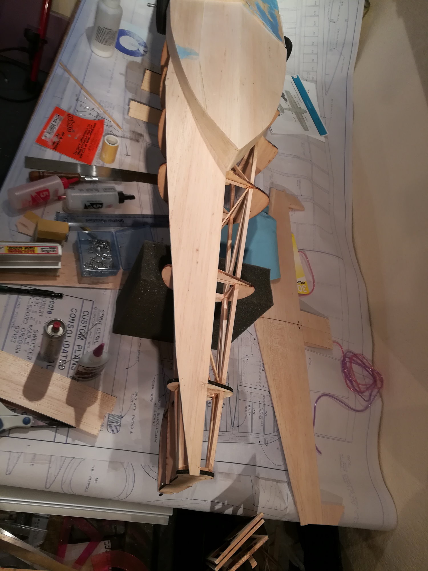
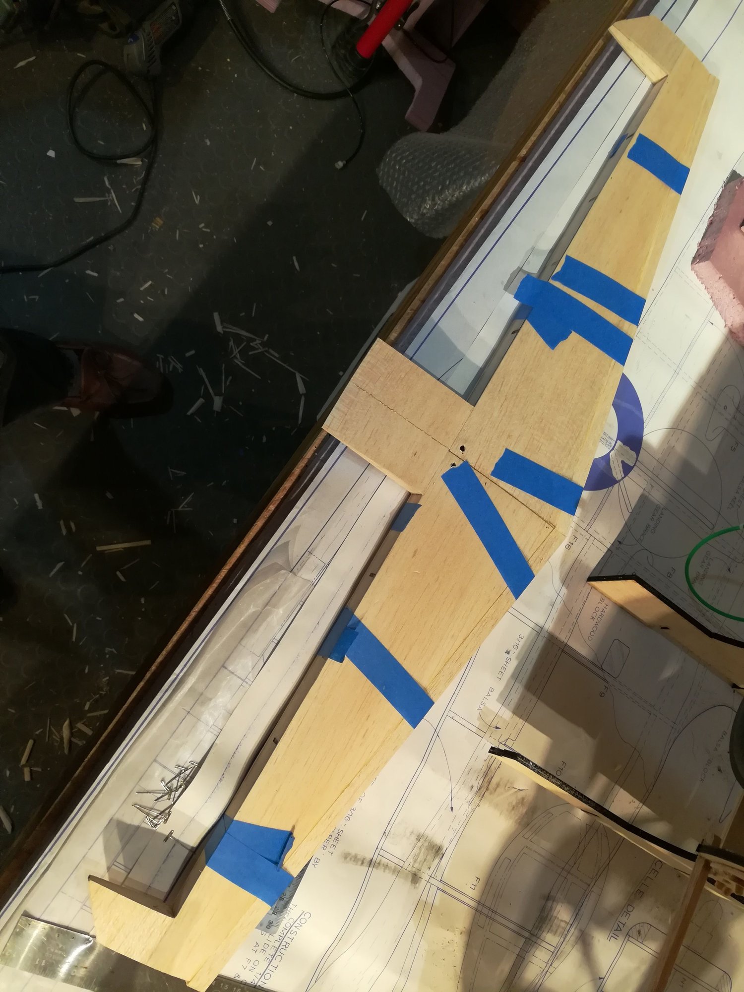
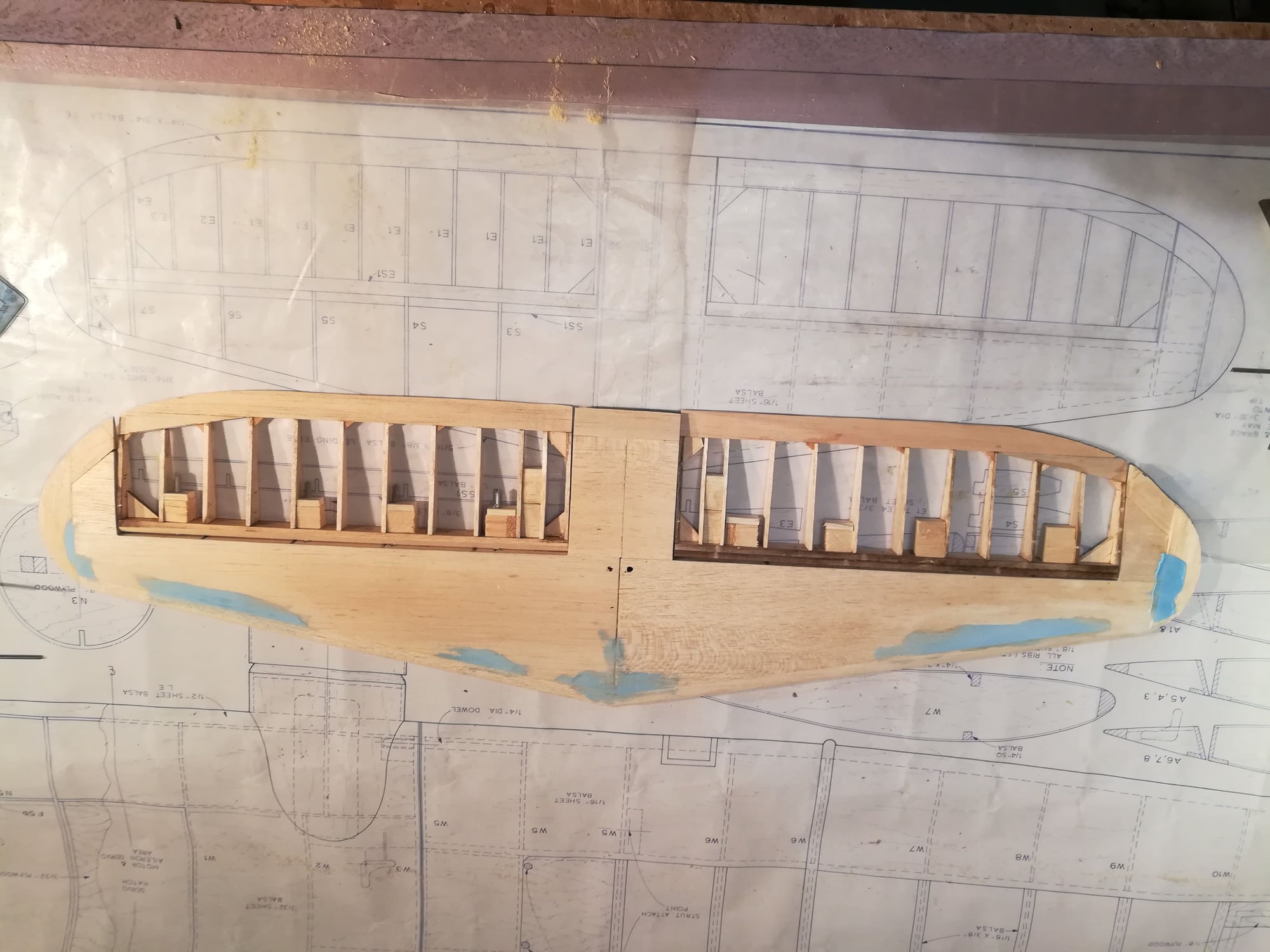
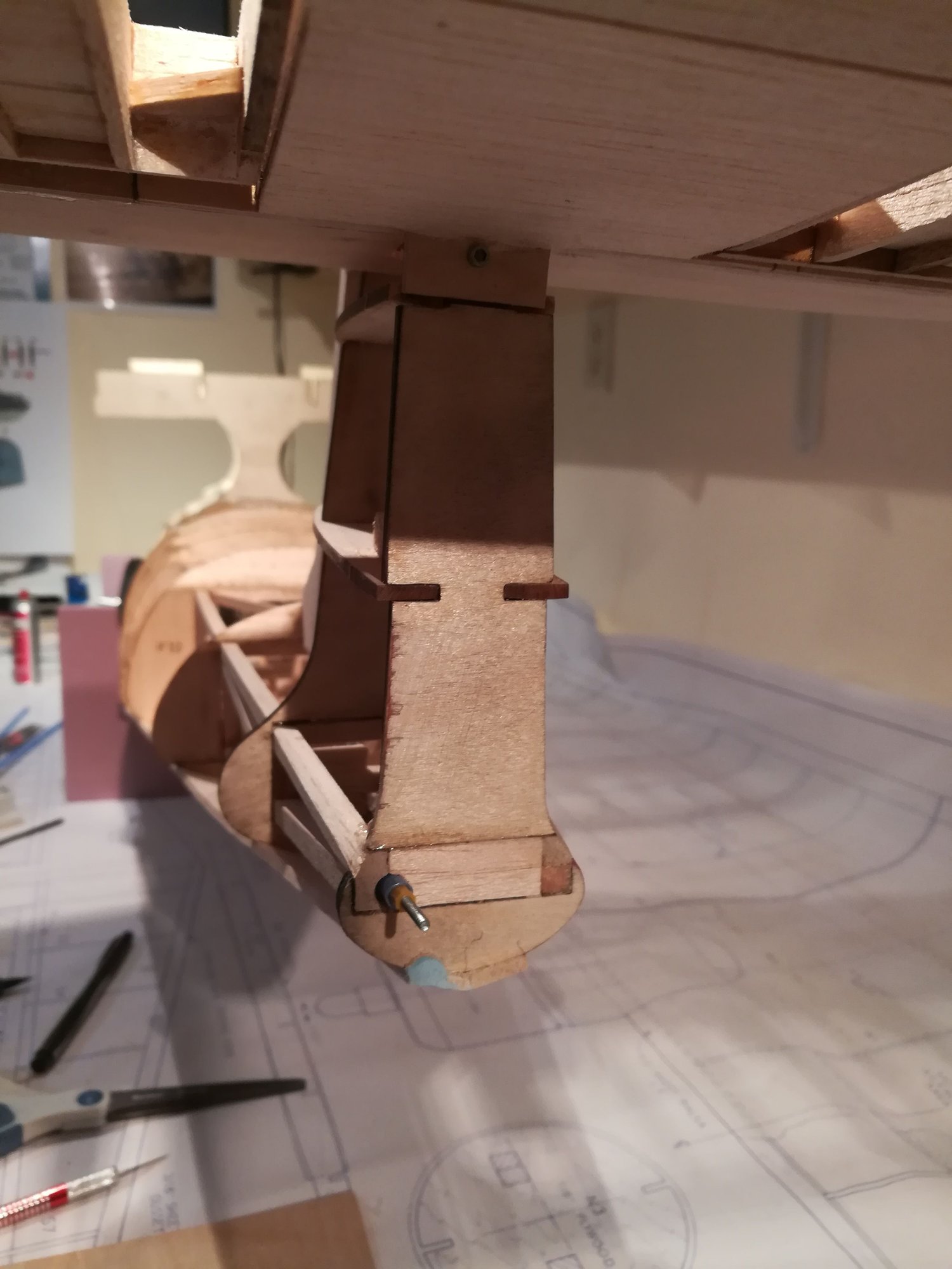
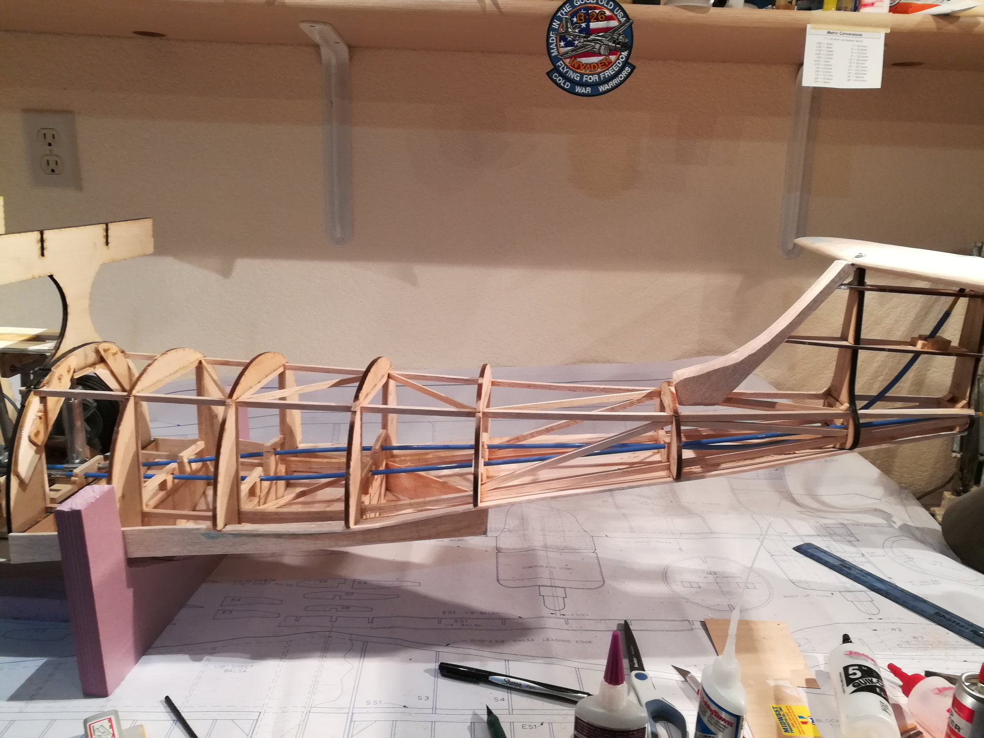
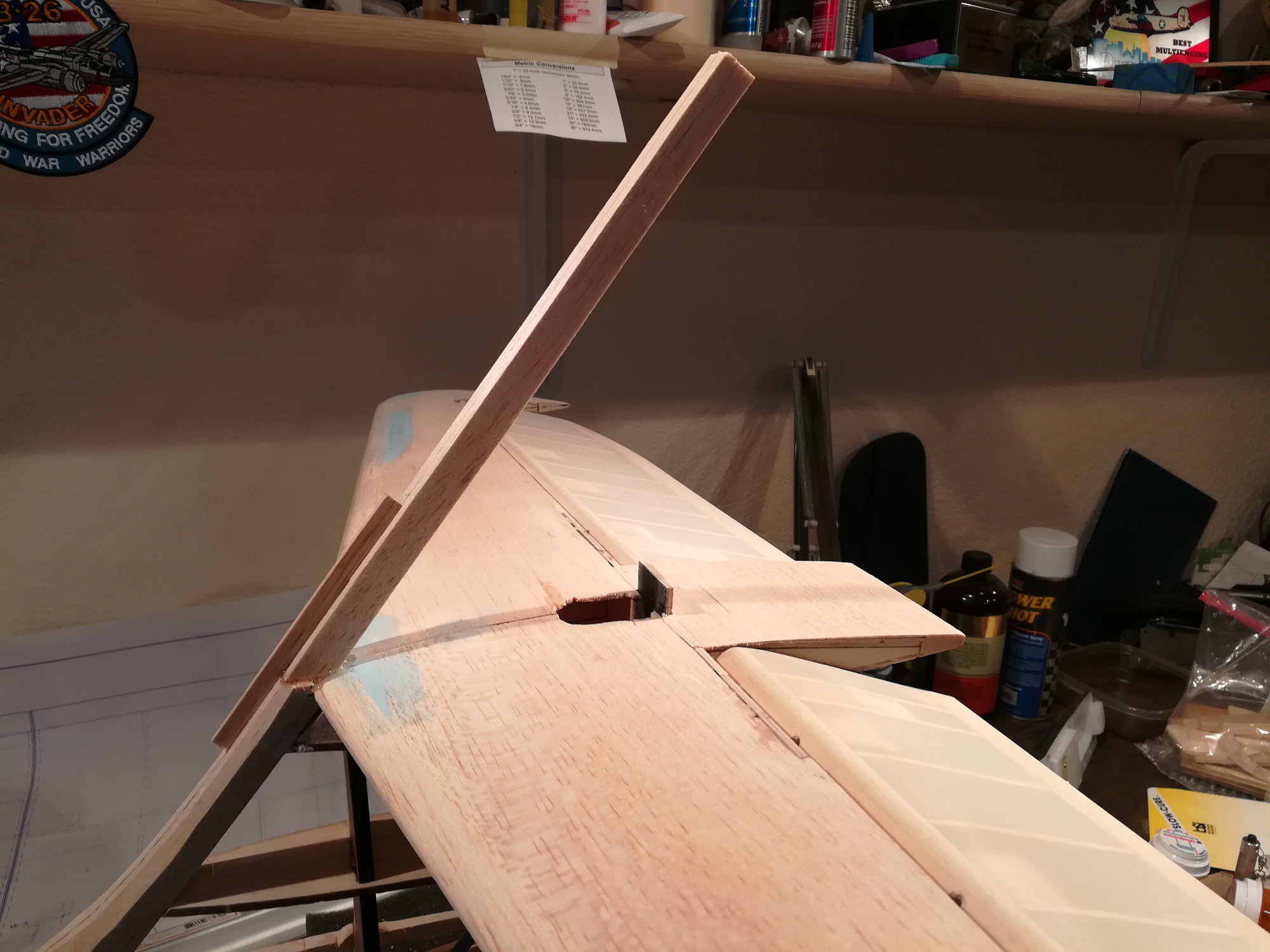
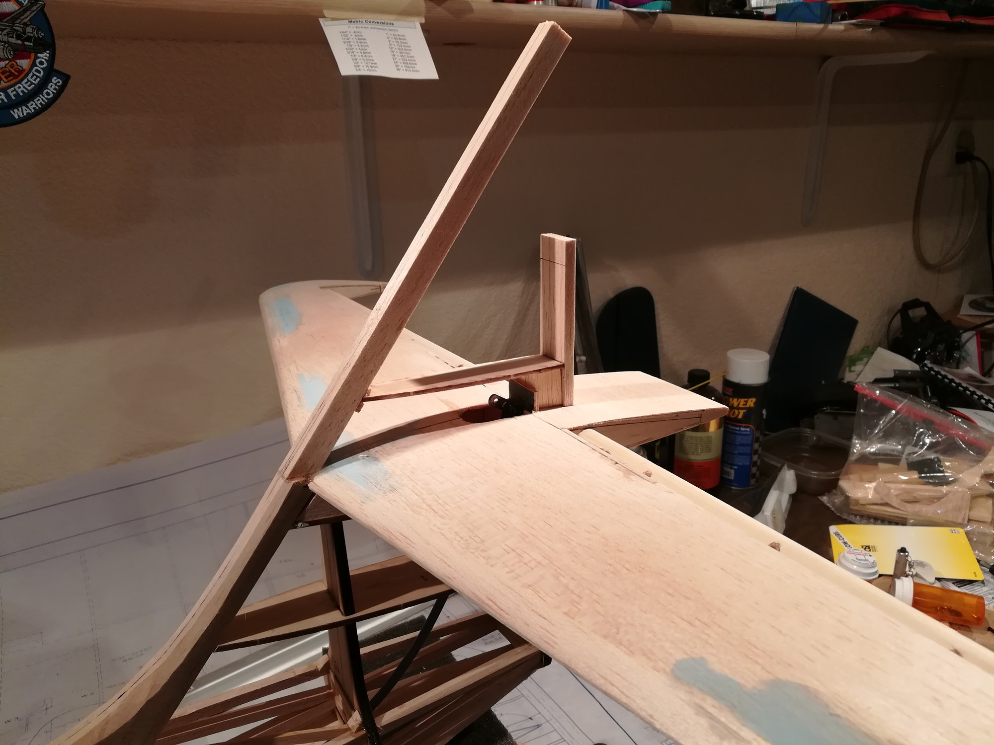
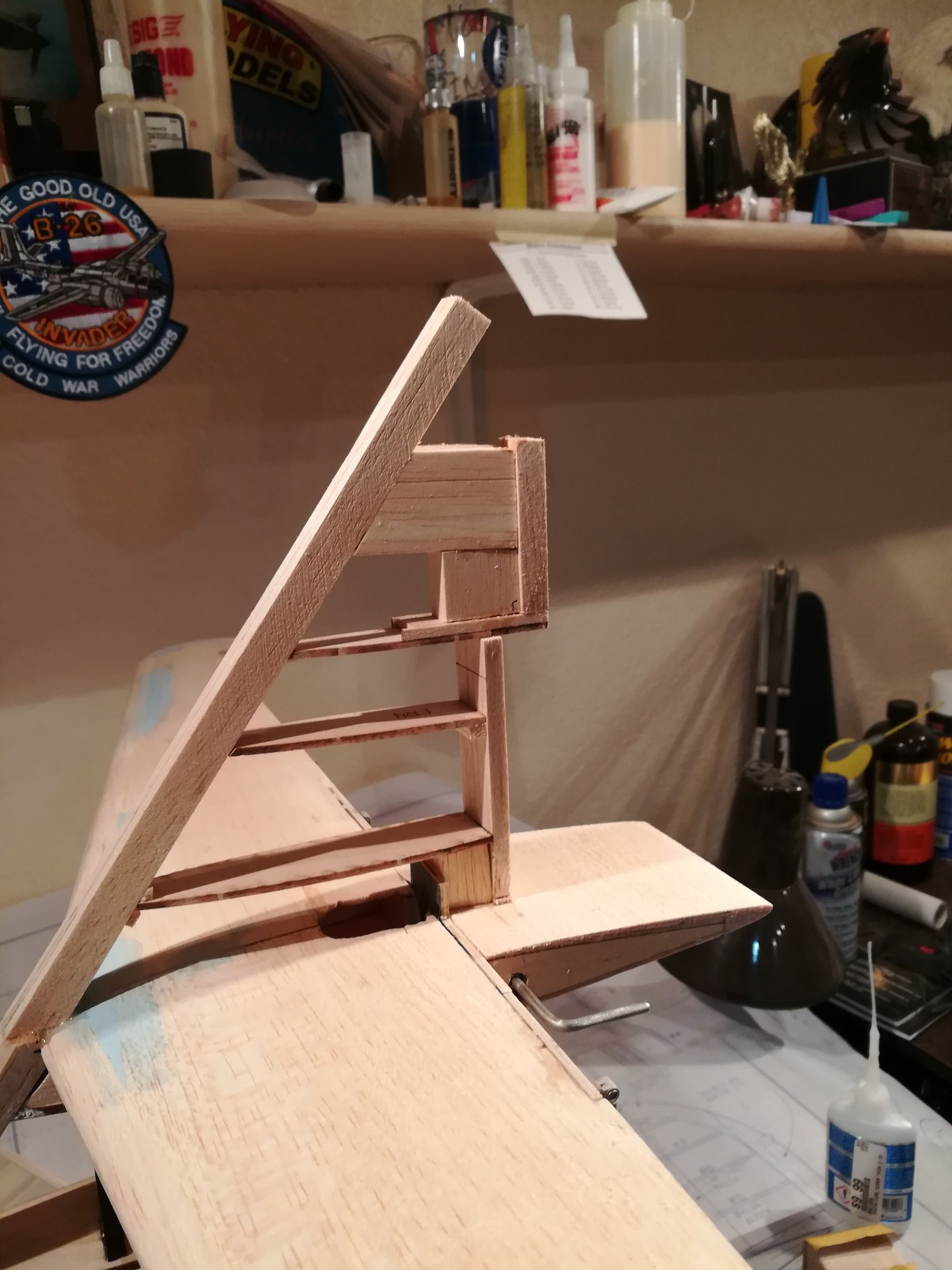
The remainder of the V-stab is built on top of the H-Stab. To keep the LE line of the V-stab perfectly straight, I glued that in first with an alignment guide, then built the rest of the V-stab.

02-10-2019, 06:57 PM
#37
Thread Starter
Join Date: Nov 2005
Location: fort collins,
CO
Posts: 448
Likes: 0
Received 0 Likes
on
0 Posts
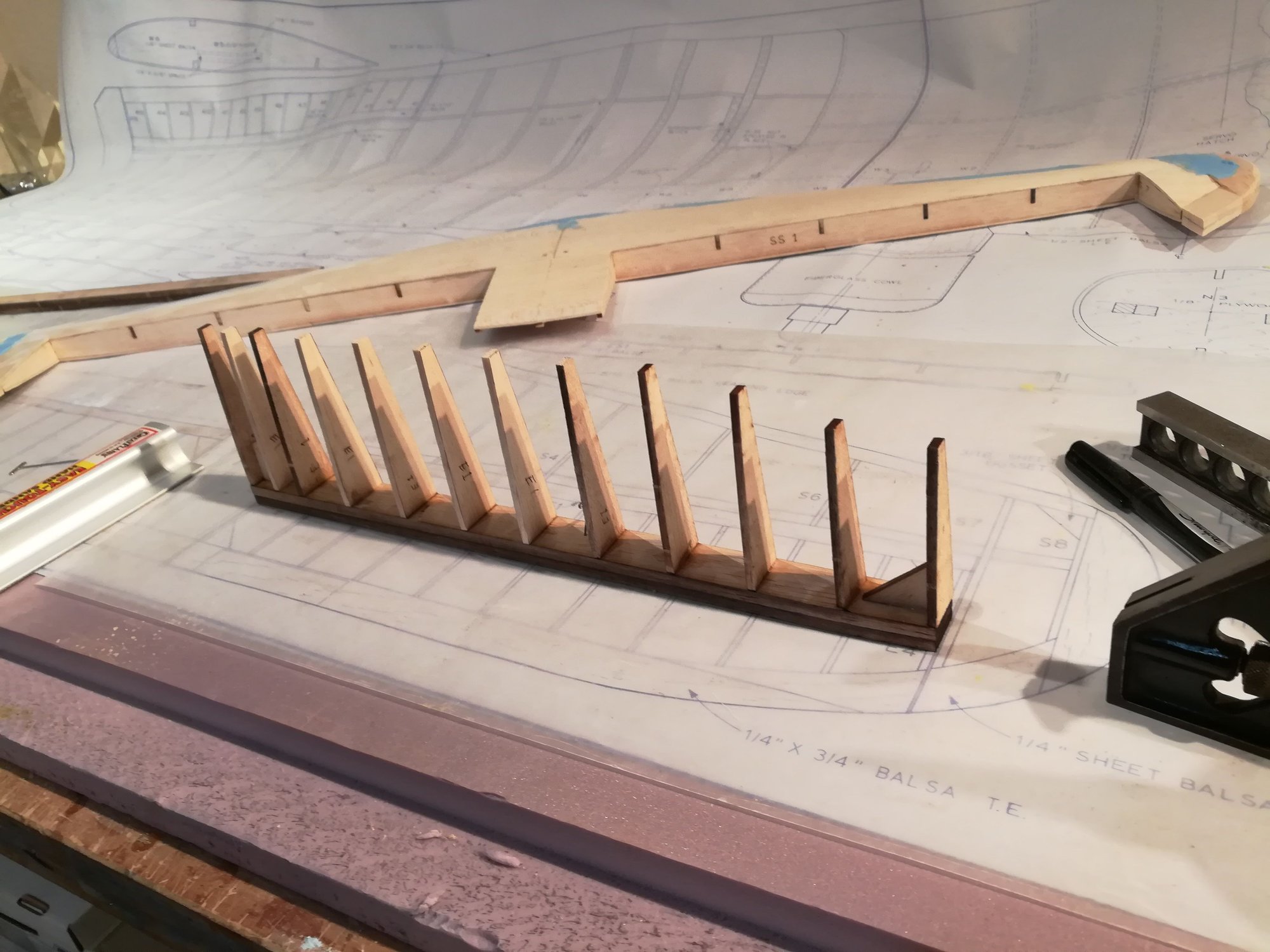
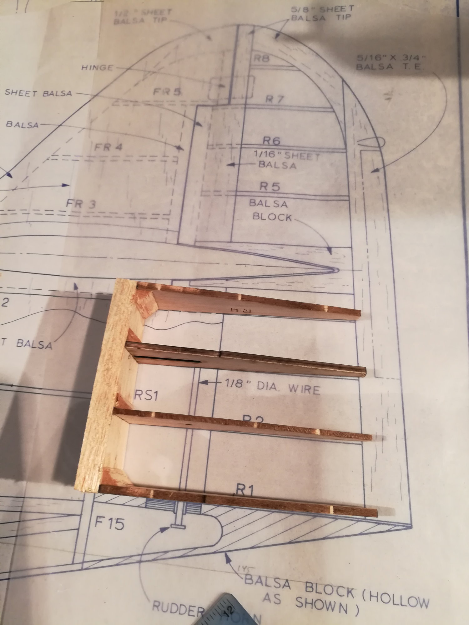
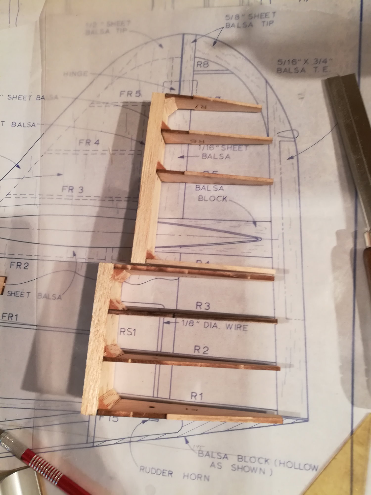
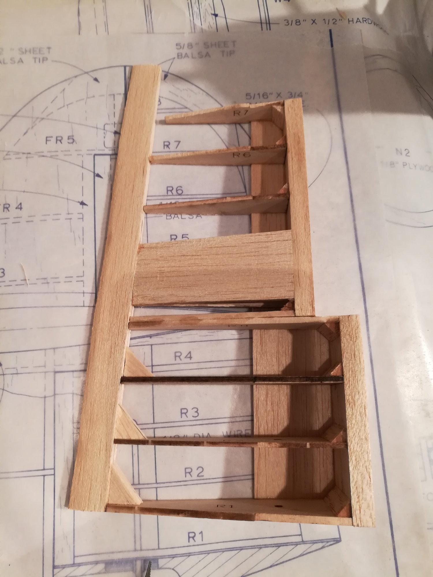
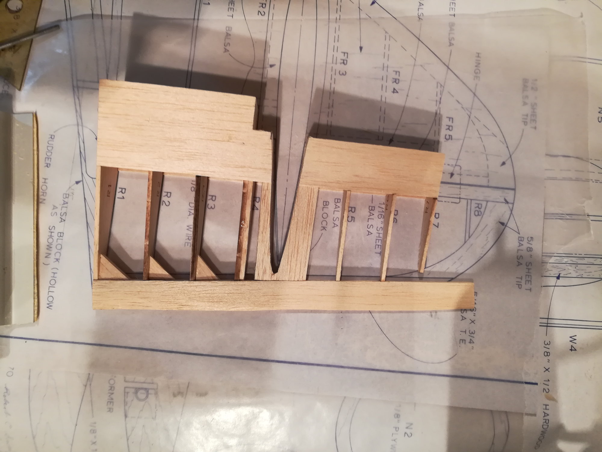
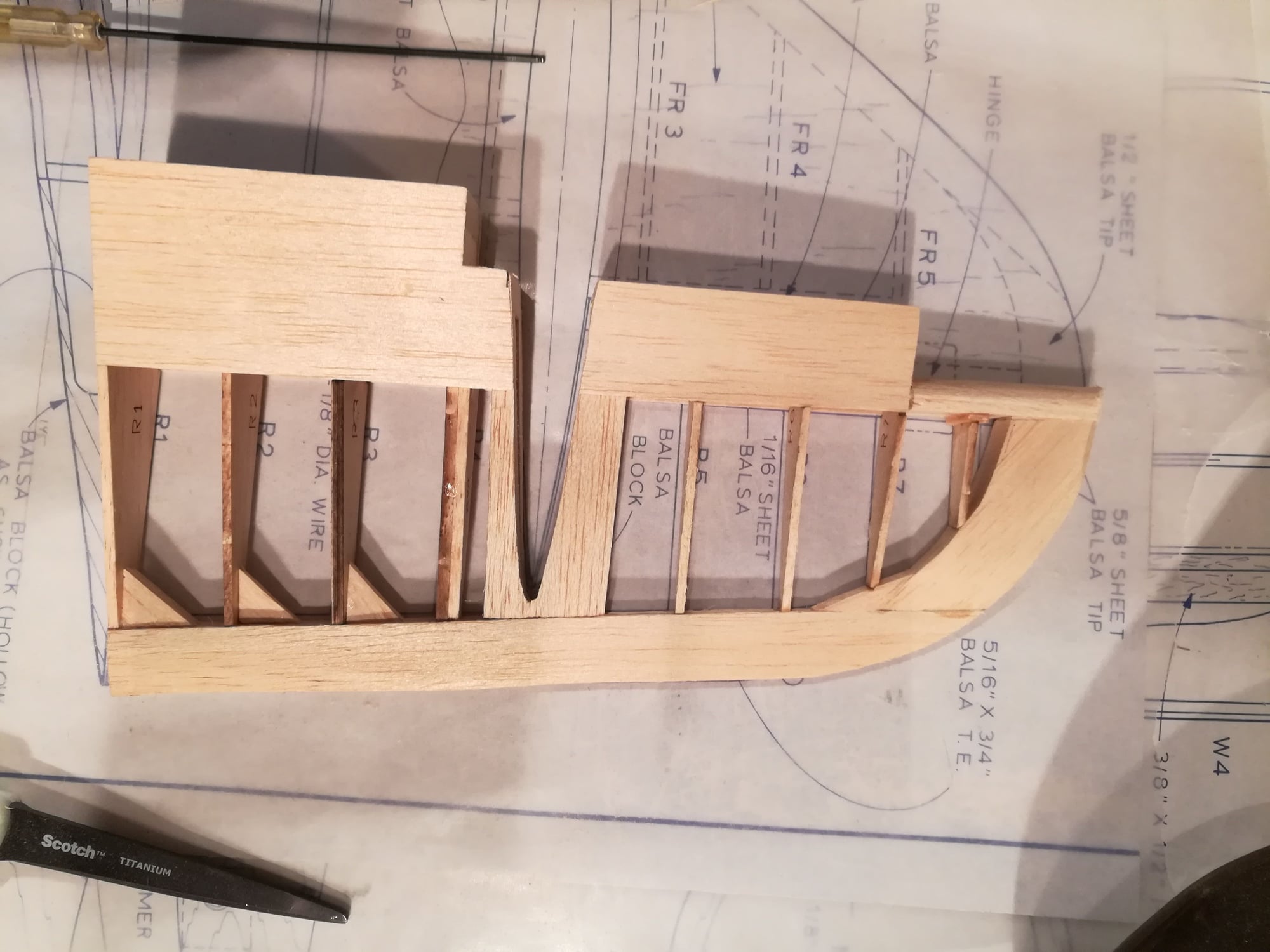
The rudder has a 3 step pattern to it, where it mates to the V-stab. It also has a cutout for the H-stab as the rudder wraps around the H-stab. Adding to this complexity, I discovered that the plans are slightly, but materially, smaller than the cut parts. As the rudder must fit like a puzzle piece with the V-stab, I opted to build in free hand, section by section to get it to mate properly. I'm showing it over the plans just so you can see what I am building.
 02-11-2019, 04:57 AM
#40
Eldher - really enjoying watching your build. By the way, settle an argument between my friend and I. What is the blue stuff you are using as a fill material? I may have missed it, but how did you decide to stiffen/support the area around F-7 and the landing gear area? Many thanks. Chic
02-14-2019, 06:15 AM
#41

Great build, will be watching as this one has been on my build list for years,
just don't have enough time to build all the planes from the plans that I have
purchased over the years. Subscribed.
BTW who did the laser cutting of this plan?
Bill D.
just don't have enough time to build all the planes from the plans that I have
purchased over the years. Subscribed.
BTW who did the laser cutting of this plan?
Bill D.
 02-23-2019, 04:19 PM
#45
Thread Starter
Join Date: Nov 2005
Location: fort collins,
CO
Posts: 448
Likes: 0
Received 0 Likes
on
0 Posts
Eldher - really enjoying watching your build. By the way, settle an argument between my friend and I. What is the blue stuff you are using as a fill material? I may have missed it, but how did you decide to stiffen/support the area around F-7 and the landing gear area? Many thanks. Chic
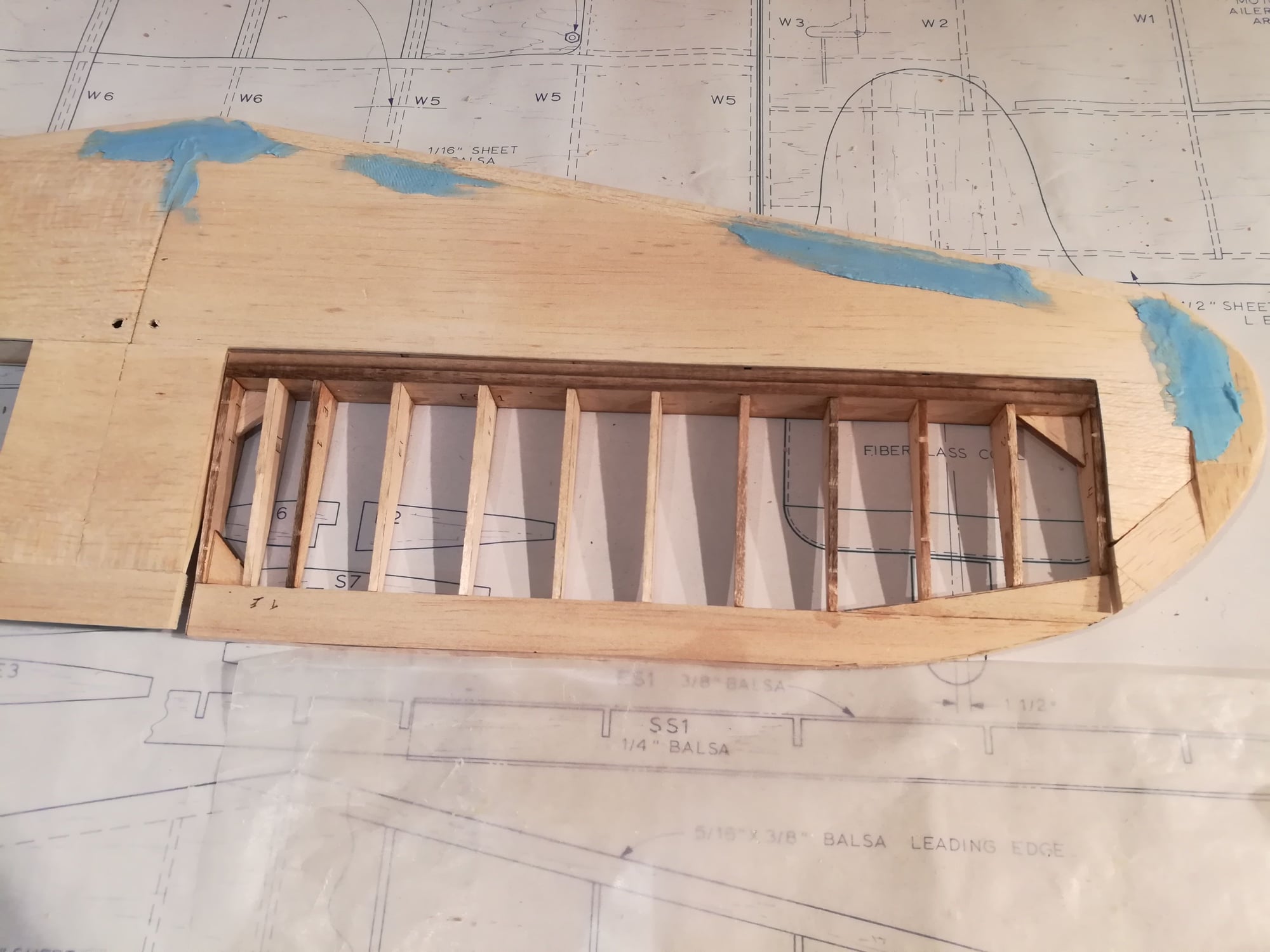
The blue stuff is SuperFil by Poly Fiber Aircraft Coatings. I love the stuff.
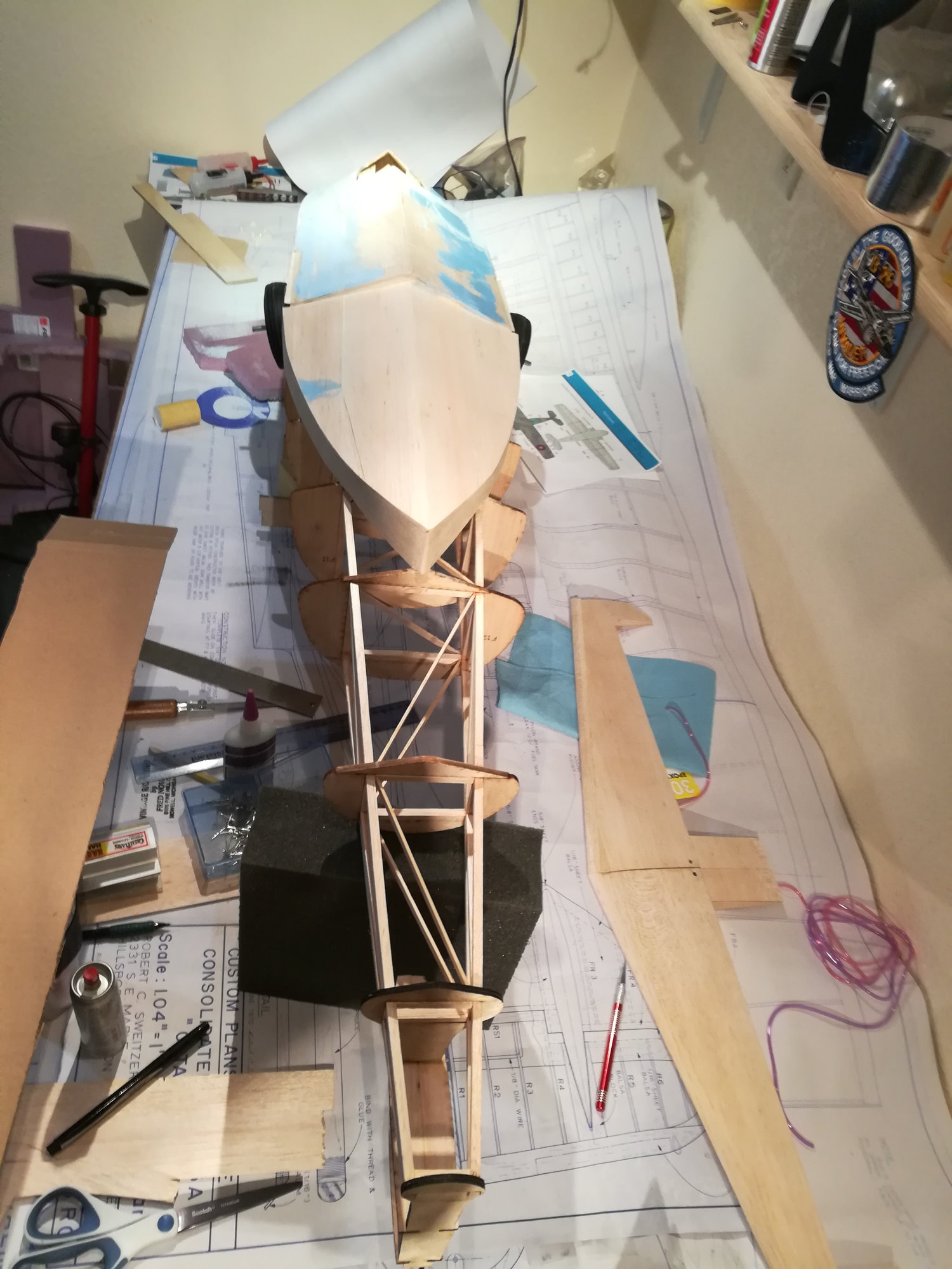
As for stiffening the opening left by F7. There are now 1/4" ply rails running lengthwise in the opening at the top and bottom of the fuse between F5 and F8. At the top are 2 rails 1" wide each at the bottom are 2 rails 2" wide each. There are then 1.5" wide x 1/4" thick ply rails across the fuse tying the left and right 2" wide rails together forming a box that the landing gear is mounted to and providing stiffening for the lower part of the fuse. Also, F7 still exists below the bottom 2" wide rails. This means that for the bottom 1/4 of the fuse the only thing that has been removed between F5 and F8 are the 1/4" sq balsa rails. For the upper area of F7, there are the 1" wide x 1/4" thick rails that you can see. I have since installed diagonal braces into the pylon and installed the part of F7 that is above the gear. See the next post where I talk about this.
02-23-2019, 04:27 PM
#46
Thread Starter
Join Date: Nov 2005
Location: fort collins,
CO
Posts: 448
Likes: 0
Received 0 Likes
on
0 Posts
A friend of mine Bill is a kit designer (he makes some nice fiberglass kits, see SCALE RC AIRPLANES) and was reviewing my alterations. He pointed out that the ply rail at the top end of the gear support could fail in a hard landing. Looking at it i agree. 
So, I have added diagonal bracing above the 1/4" ply and installed the section of F7 that fit above the gear (in the pylon). Net result is that the landing loads can be transmitted to the pylon and wing. Also, this will significantly stiffen the upper area between F5 and F8.

So, I have added diagonal bracing above the 1/4" ply and installed the section of F7 that fit above the gear (in the pylon). Net result is that the landing loads can be transmitted to the pylon and wing. Also, this will significantly stiffen the upper area between F5 and F8.
02-23-2019, 04:37 PM
#47
Thread Starter
Join Date: Nov 2005
Location: fort collins,
CO
Posts: 448
Likes: 0
Received 0 Likes
on
0 Posts
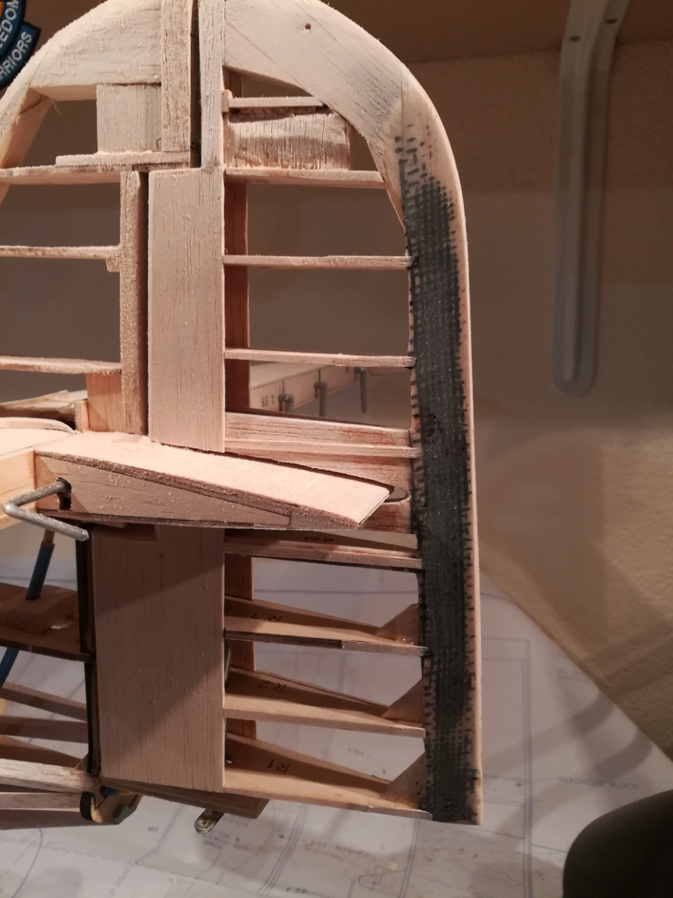
An issue with this rudder is that it is hinged only at the top and bottom. Flight and torsion loads are transmitted through the trailing edge (yuck). To deal with this, I have added carbon fiber cloth to both sides of the rudder TE. It's quite strong now!

 02-23-2019, 04:47 PM
#48
Thread Starter
Join Date: Nov 2005
Location: fort collins,
CO
Posts: 448
Likes: 0
Received 0 Likes
on
0 Posts
Overall, I think it's mitigated by a couple things. First, the original design was set up with this long path. Second, this plane will likely top out at 40 MPH. Third if it is an issue I can cut 15" off the length of the pushrod by mounting the servo under one of the gun blisters instead of in the nose.
02-23-2019, 04:50 PM
#49
Thread Starter
Join Date: Nov 2005
Location: fort collins,
CO
Posts: 448
Likes: 0
Received 0 Likes
on
0 Posts
02-24-2019, 08:14 PM
#50
Thread Starter
Join Date: Nov 2005
Location: fort collins,
CO
Posts: 448
Likes: 0
Received 0 Likes
on
0 Posts
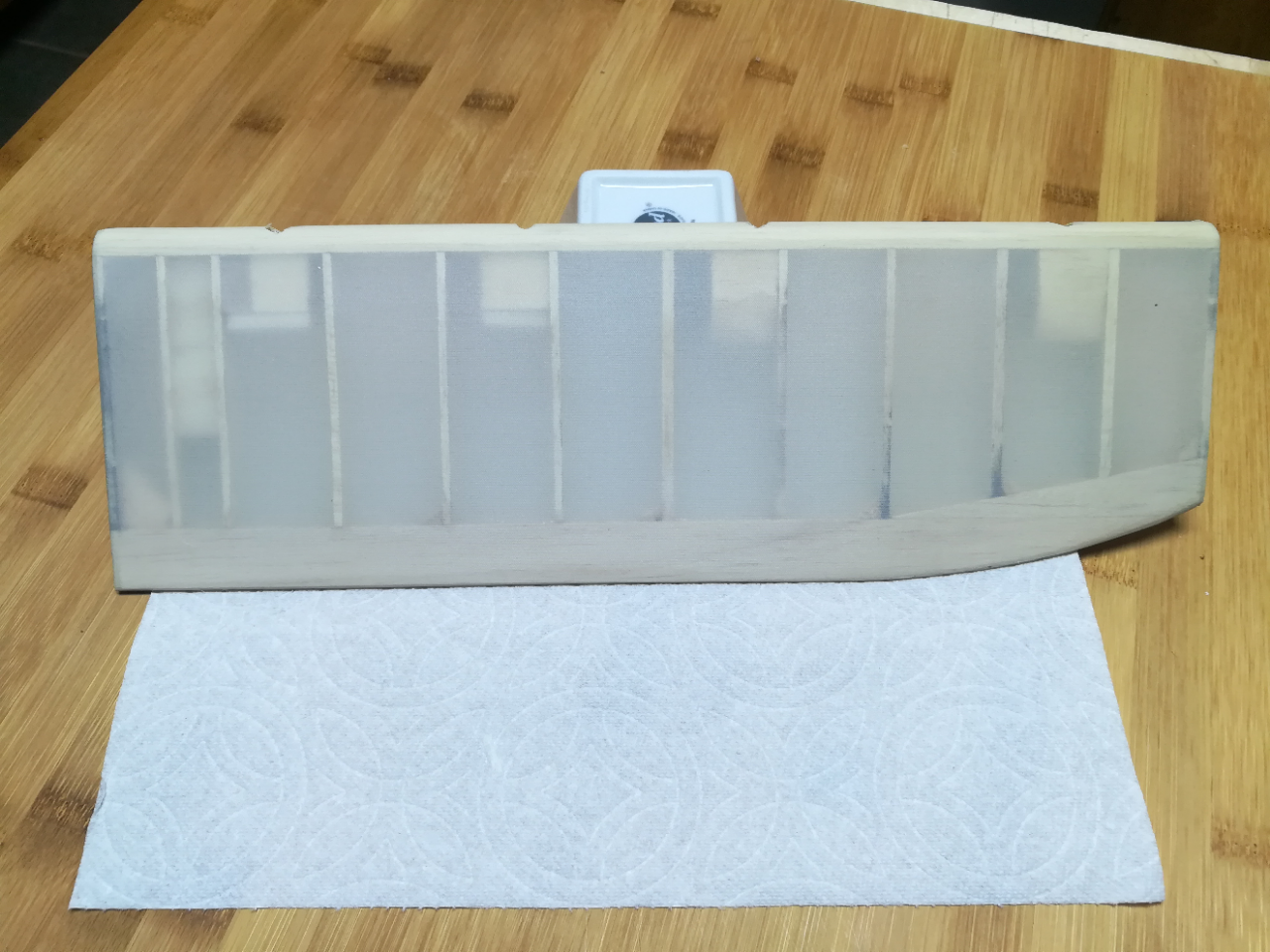
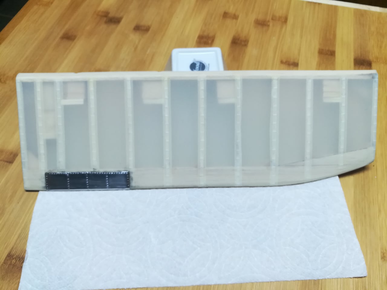
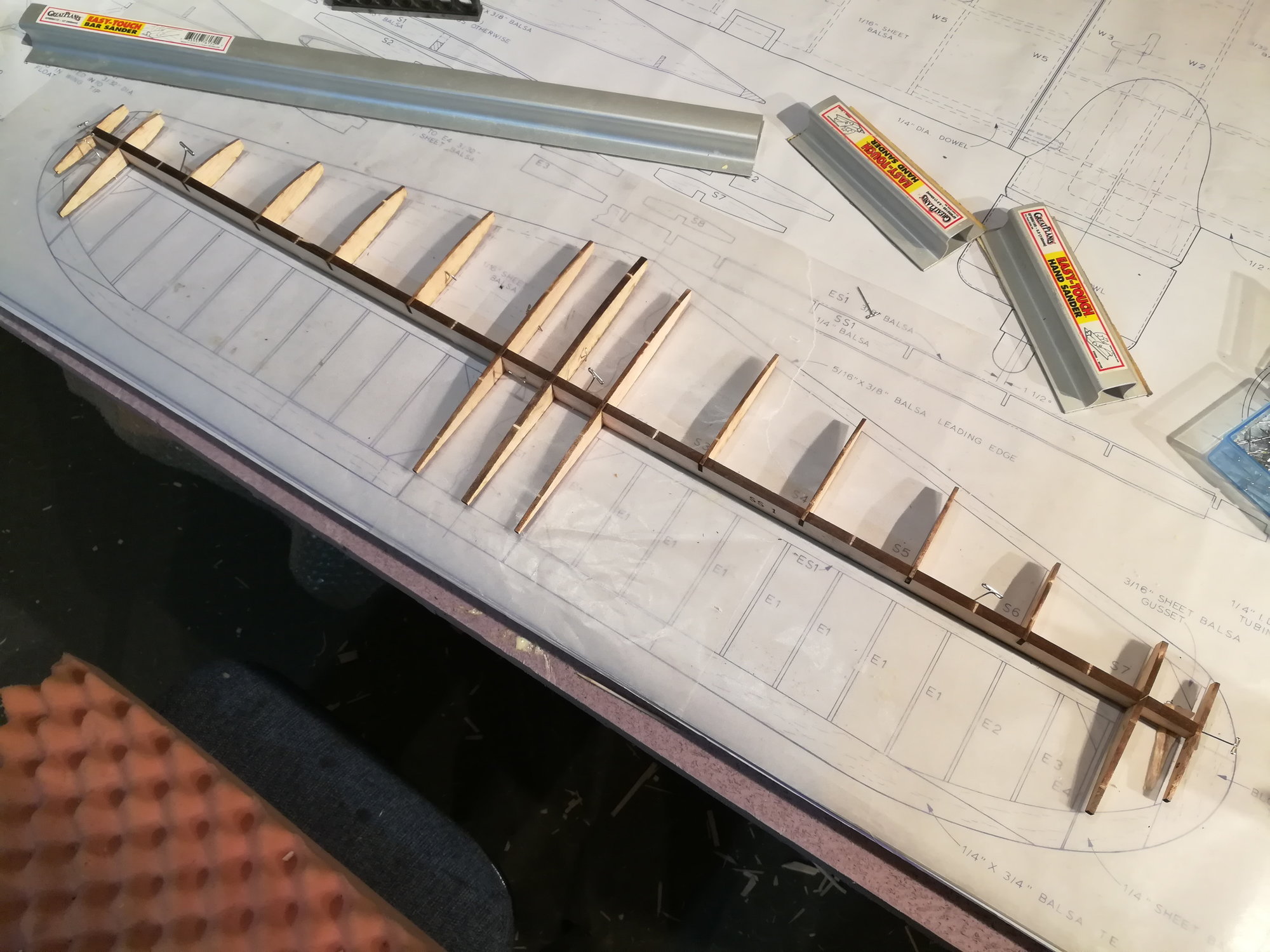
Decided to set the sand paper aside for a bit and play with some scale details. For those not familiar with the Cat, the elevators, rudder, and 1/3 of the wing (chord wise) are fabric covered. This is stitched to the ribs. Here's a before and after shot of the elevator, which also includes the aluminum trim tab.