


FiberClassics P-51 now Comp-ARF P-51
 10-04-2016, 02:23 PM
#2351

My Feedback: (49)
Dang, lots of comments since I posted. I am subscribed here, but no notice of new comments whatsoever.
I saw several questions to me, so I'll try to get answers.
frisconick - nick, yes, planning on being at the GSW All Scale meet on Oct 15th. Yes, I was speaking of Jack and Dennis both GSW club members. The CARF is quite a bit of "blank canvas" for sure, but it's also lots of work. I might suggest looking at the Top RC Models P-51 instead. I understand it's quite nice, not as large, but way more done for you and lots less $$$. As well, the CARF P-51 instruction booklet is close to worthless.
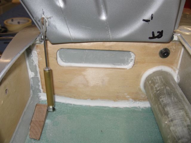
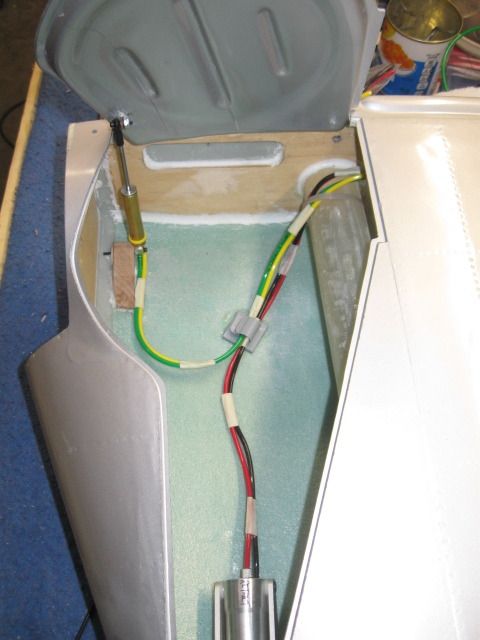
Chris Nicastro, yes, installed the Sierra tailwheel in a scale-like manner. I'll get a pic of the space under the cockpit floor for you soon. On running the air back thru the fuselage, it seems that's not all that great an idea for airflow as it looses power on the way back. An air boosting fan would be nice to help it along. I am dumping the air right back out in front of the wing - in and out quickly. But, hope your plan works out.
I saw several questions to me, so I'll try to get answers.
frisconick - nick, yes, planning on being at the GSW All Scale meet on Oct 15th. Yes, I was speaking of Jack and Dennis both GSW club members. The CARF is quite a bit of "blank canvas" for sure, but it's also lots of work. I might suggest looking at the Top RC Models P-51 instead. I understand it's quite nice, not as large, but way more done for you and lots less $$$. As well, the CARF P-51 instruction booklet is close to worthless.
Chris Nicastro, yes, installed the Sierra tailwheel in a scale-like manner. I'll get a pic of the space under the cockpit floor for you soon. On running the air back thru the fuselage, it seems that's not all that great an idea for airflow as it looses power on the way back. An air boosting fan would be nice to help it along. I am dumping the air right back out in front of the wing - in and out quickly. But, hope your plan works out.


 10-19-2016, 05:04 AM
#2356
My Feedback: (49)
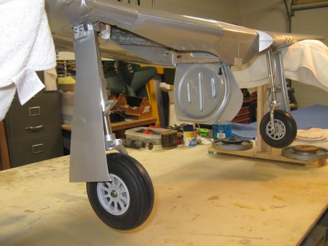
Made some more progress. Got the retracts going and the doors as well. Takes some time and some guidance from someone who has done this before. A fellow club member loaned me his CARF wing to look at. Wouldn't have been able to get all the parts in place without that.
All this is "mocked up" just to get the alignments correct. Helps from making errors that are hard to repair.
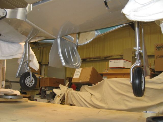
Getting the strut cover situated with the retract is very time consuming if you have not done this before.
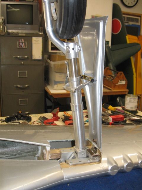
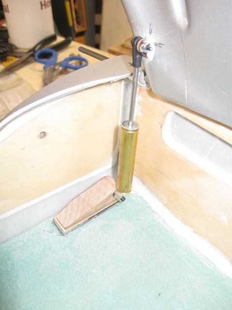
Close up of the strut cover attachment. This is the patience-tester! You can adjust the height of the turnbuckle support as well to fine tune the doors closing all the way. I made a hinge from a large piano hinge, but it won't be suitable for the finished deal. Going to use a small hinge from the hardware store. That area is just CA'd in place for mock-up. You have to make a small block to rest the huge on as there is a gap there. The door must be on the same plane as the rest of the wing and must be aligned with the cutout when closed. This will give you trouble until you get it down. I had to move the retract assembly about 0.200" toward the leading edge to get the strut and strut cover to line up. Also requires a small "up" tilt to keep the tire off the wing spar tube.
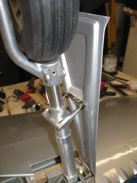
UP two-inch throw air cylinder. Will change out to the larger 7/16" diameter version with 4-40 rod for more power on the inner doors.
Doors fit pretty tight, but need to make some adjustments to the turnbuckles.
All this is "mocked up" just to get the alignments correct. Helps from making errors that are hard to repair.
Getting the strut cover situated with the retract is very time consuming if you have not done this before.
Close up of the strut cover attachment. This is the patience-tester! You can adjust the height of the turnbuckle support as well to fine tune the doors closing all the way. I made a hinge from a large piano hinge, but it won't be suitable for the finished deal. Going to use a small hinge from the hardware store. That area is just CA'd in place for mock-up. You have to make a small block to rest the huge on as there is a gap there. The door must be on the same plane as the rest of the wing and must be aligned with the cutout when closed. This will give you trouble until you get it down. I had to move the retract assembly about 0.200" toward the leading edge to get the strut and strut cover to line up. Also requires a small "up" tilt to keep the tire off the wing spar tube.
UP two-inch throw air cylinder. Will change out to the larger 7/16" diameter version with 4-40 rod for more power on the inner doors.
Doors fit pretty tight, but need to make some adjustments to the turnbuckles.
10-23-2016, 08:15 PM
#2357
My Feedback: (49)
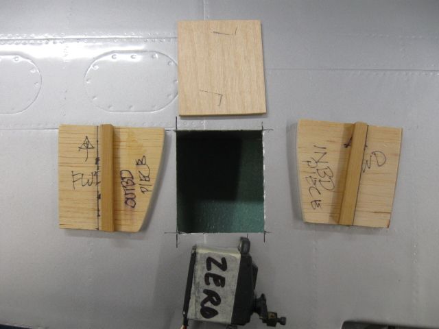
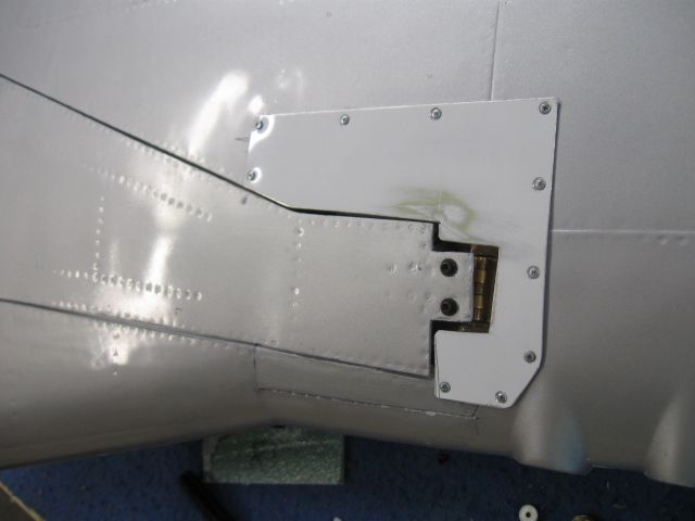
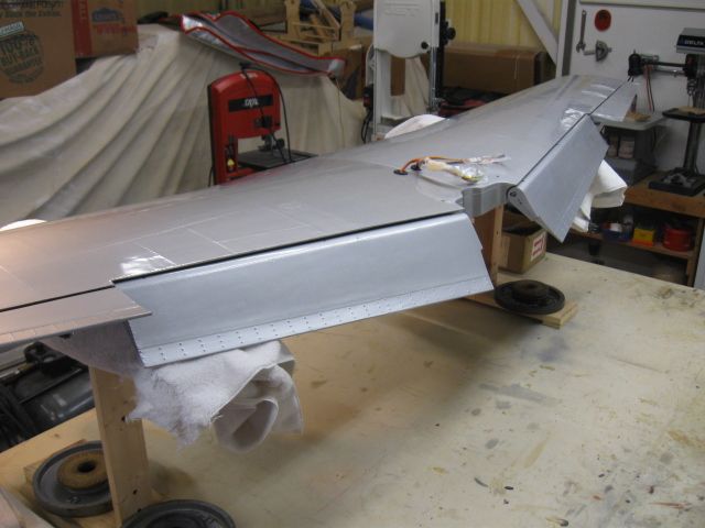
Started on mounting the wing servos. Got the cutouts made and the aileron servo pretty well tucked in. Copied the CARF P-51 wing half from a fellow club member who loaned me his to go by. He made some inserts that glued into the wing cutouts and go from top to bottom wing skins. A mounting shelf of spruce square stock is there to rest the servo platform on and that's pretty much it. The black line is obviously the 90 degree line to the aileron control horn.
I show this for folks who might be thinking of how to mount the servos in a hollow wing. Without top to bottom support, the wing might flex in that area.
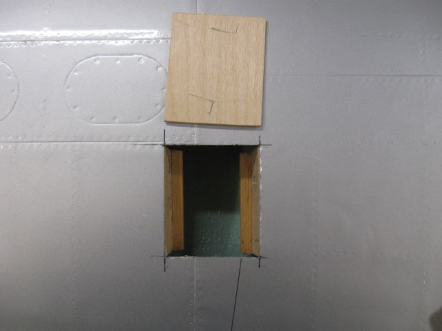
The side pieces are cut to the wing contours, a spruce mount added to each side.
Side pieces epoxied in place and ready for the servo platform.
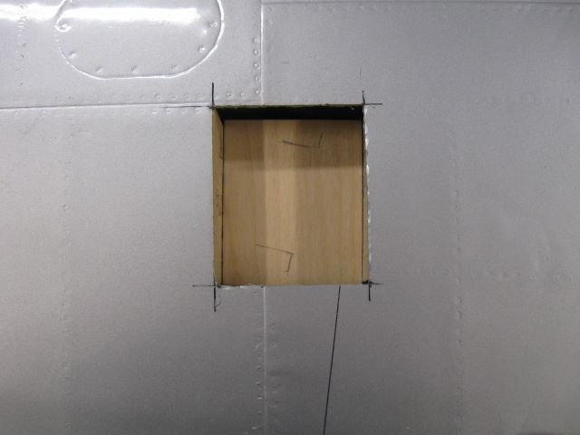
Servo platform in place. Make it removable for future access.
Futaba full sized HTMG 3305 servo in place and angled at the aileron control horn, when I get it done. ha. The servo hole will be covered with lithoplate aluminum.
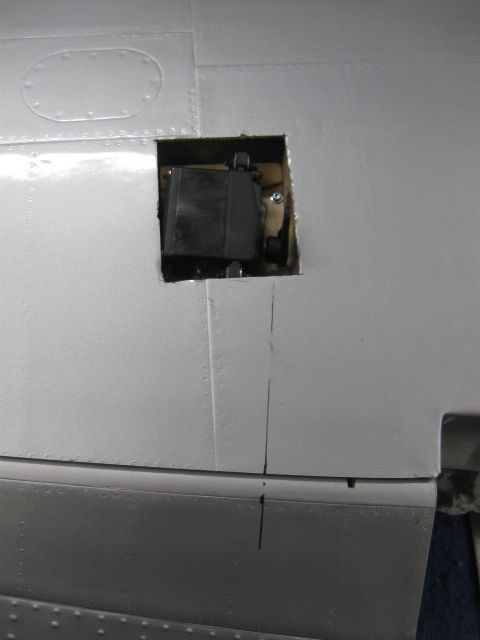
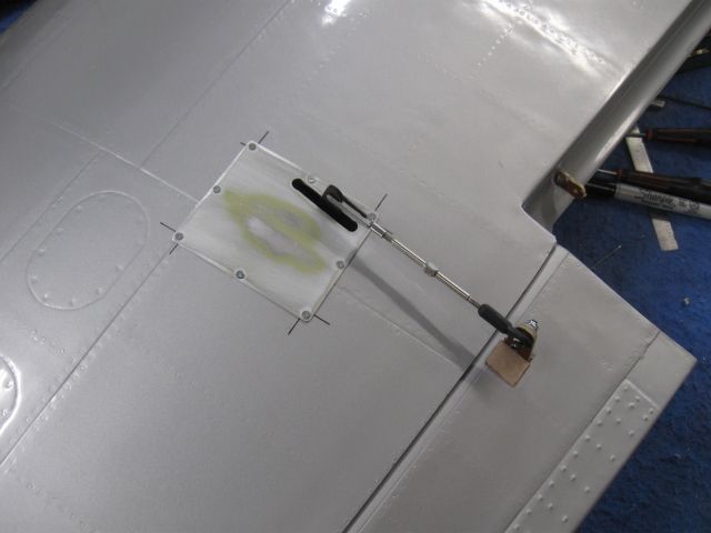
Finally got the aileron servo installed. I work slow. Used some 0.018" sheet aluminum for the cover and #1 sheet metal screws around the edges. It's a very solid aileron setup. I'll change the linkage a bit later, but the 4-40 ball link on the control horn will stay. I think I will use Dubro Qwik Link connectors on the servo arm and a 4-40 rod. That turnbuckle may not be the right length.
I show this for folks who might be thinking of how to mount the servos in a hollow wing. Without top to bottom support, the wing might flex in that area.
The side pieces are cut to the wing contours, a spruce mount added to each side.
Side pieces epoxied in place and ready for the servo platform.
Servo platform in place. Make it removable for future access.
Futaba full sized HTMG 3305 servo in place and angled at the aileron control horn, when I get it done. ha. The servo hole will be covered with lithoplate aluminum.
Finally got the aileron servo installed. I work slow. Used some 0.018" sheet aluminum for the cover and #1 sheet metal screws around the edges. It's a very solid aileron setup. I'll change the linkage a bit later, but the 4-40 ball link on the control horn will stay. I think I will use Dubro Qwik Link connectors on the servo arm and a 4-40 rod. That turnbuckle may not be the right length.
Last edited by LBJ; 10-24-2016 at 01:58 PM.
10-30-2016, 04:45 AM
#2358

Made some more progress. Got the retracts going and the doors as well. Takes some time and some guidance from someone who has done this before. A fellow club member loaned me his CARF wing to look at. Wouldn't have been able to get all the parts in place without that.
All this is "mocked up" just to get the alignments correct. Helps from making errors that are hard to repair.
Getting the strut cover situated with the retract is very time consuming if you have not done this before.
Close up of the strut cover attachment. This is the patience-tester! You can adjust the height of the turnbuckle support as well to fine tune the doors closing all the way. I made a hinge from a large piano hinge, but it won't be suitable for the finished deal. Going to use a small hinge from the hardware store. That area is just CA'd in place for mock-up. You have to make a small block to rest the huge on as there is a gap there. The door must be on the same plane as the rest of the wing and must be aligned with the cutout when closed. This will give you trouble until you get it down. I had to move the retract assembly about 0.200" toward the leading edge to get the strut and strut cover to line up. Also requires a small "up" tilt to keep the tire off the wing spar tube.
UP two-inch throw air cylinder. Will change out to the larger 7/16" diameter version with 4-40 rod for more power on the inner doors.
Doors fit pretty tight, but need to make some adjustments to the turnbuckles.
No no toe In?
10-30-2016, 07:58 AM
#2359
My Feedback: (49)
luckymacy, yep, got toe-in. In fact, have to have it to clear the spar tube. I also had to go in and redo the strut cover install because it still wasn't exactly correct. I posted a long story of how to do the doors on RCSB, so wander over there if you have access to that site. It's under the LANDING GEAR forum. Long story short, even though I got the strut cover to lineup in the wing opening as shown above, it was very skewed and would likely have given me trouble down the line. I had to make the hinge exactly square to the strut pivot axis first and foremost. I failed to do that on the first try. Now it works effortlessly.
10-30-2016, 08:26 PM
#2360
My Feedback: (49)
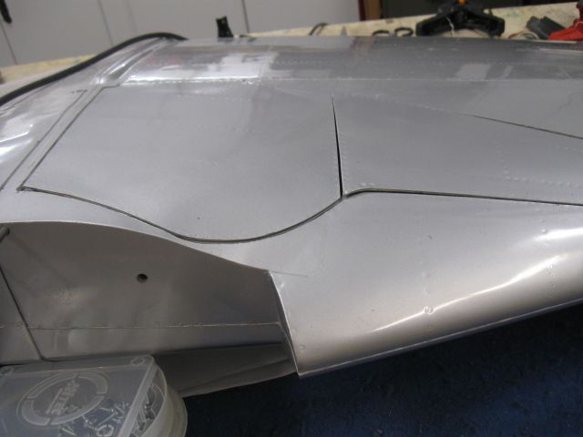
Made a frame around the cutouts for the landing gear mounting - I cut it way too big by following the CARF instruction booklet, which is useless. Used 0.018" tempered aluminum sheet and #2 flat head screws from Micro Fasteners.
Got the larger air cylinder in from Dream Works and installed it. The right wing half is pretty much done, now to the left half.
Got the larger air cylinder in from Dream Works and installed it. The right wing half is pretty much done, now to the left half.
11-12-2016, 06:09 AM
#2361
lets see how and where you decided to T and quick connect the airlines and route them or bulkhead mount them or how much slack you needed to leave for convenient connection when joining the wing halves and mating to the fuselage.
11-12-2016, 07:08 AM
#2362
My Feedback: (49)
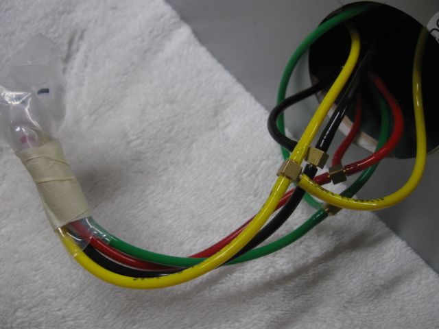
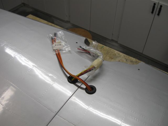
This shows the Tee setup. Lines come out of the wheel well and over to the servo lead side where they are Tee'd off and then goes out thru the top wing skin. Other end of Tee goes to the opposite side of wing. Connectors are covered because the shop is filthy and no telling how long they will wait till being used.
I used Dream Works air lines since they are color coded. Much stronger than Robart lines. Not expensive either. Come in 12 foot lengths. Several more colors to pick from. Order the lines with code "AL" in the part numbers as they have 3mm and 4mm lines as well. The "AL" part numbers fit standard brass nipples such as found on Robart and Sierra gear. They are a bit more struggle to get on the nipples but once on they are secure.
Lines out the wing and awaiting more Robart connectors. Servo leads are there, forgot to pull them out of the wing.
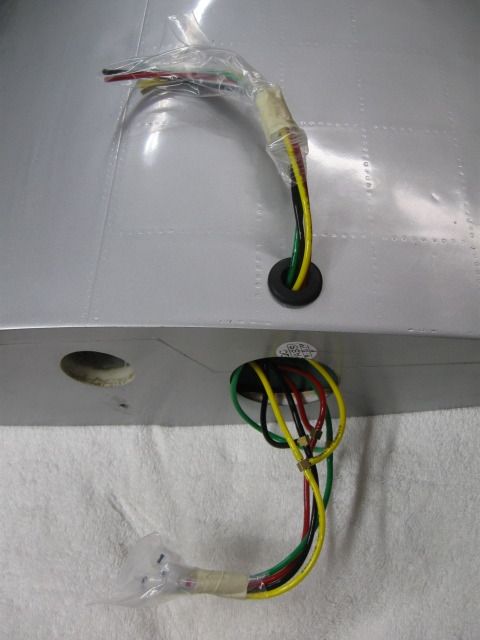
Inside the wheel well layout. Color coded for ease of hooking up the lines at the field.
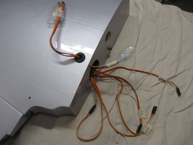
Opposite wing half has the servo leads out the top. That's pretty much it. I hope the wings are done as far as hardware install. A few details to take care of here and there perhaps, but next big thing will be paint. I do plan on setting up a full ops check to test both sides of the retracts off the UP-2 valve to make sure it's all working according to plan. Gotta make some jack stands to put the full wing on first. Good time to clean up the shop. Work table is a total mess.
I used Dream Works air lines since they are color coded. Much stronger than Robart lines. Not expensive either. Come in 12 foot lengths. Several more colors to pick from. Order the lines with code "AL" in the part numbers as they have 3mm and 4mm lines as well. The "AL" part numbers fit standard brass nipples such as found on Robart and Sierra gear. They are a bit more struggle to get on the nipples but once on they are secure.
Lines out the wing and awaiting more Robart connectors. Servo leads are there, forgot to pull them out of the wing.
Inside the wheel well layout. Color coded for ease of hooking up the lines at the field.
Opposite wing half has the servo leads out the top. That's pretty much it. I hope the wings are done as far as hardware install. A few details to take care of here and there perhaps, but next big thing will be paint. I do plan on setting up a full ops check to test both sides of the retracts off the UP-2 valve to make sure it's all working according to plan. Gotta make some jack stands to put the full wing on first. Good time to clean up the shop. Work table is a total mess.
Last edited by LBJ; 11-12-2016 at 07:16 AM.
11-12-2016, 02:19 PM
#2363
My Feedback: (49)
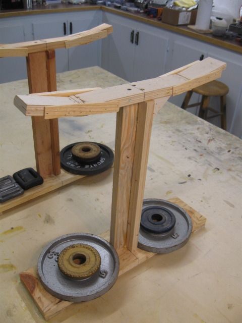
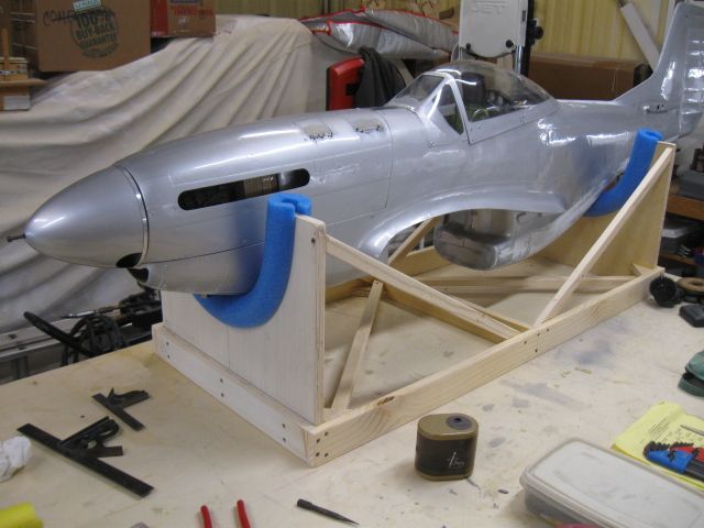
Got my work table cleared off and built some jack stands. Used what ever I had on hand. Will pad the tops with towels. Handy to have and could have used these on a number of previous models with retracts. Will test the CARF P-51 retracts and doors with the UP-2 valve soon. Too tired to do it tonight.
11-12-2016, 05:42 PM
#2364
My Feedback: (49)
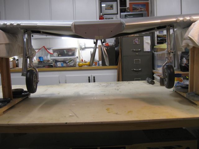
After the glue had dried, went out tonite and assembled the wing. Air lines and servo leads not connected, just to see how the wing fits the new test stand. Fits very nicely. Very stable on them. Really different to see the wing right side up.
Fullest flaps down setting.
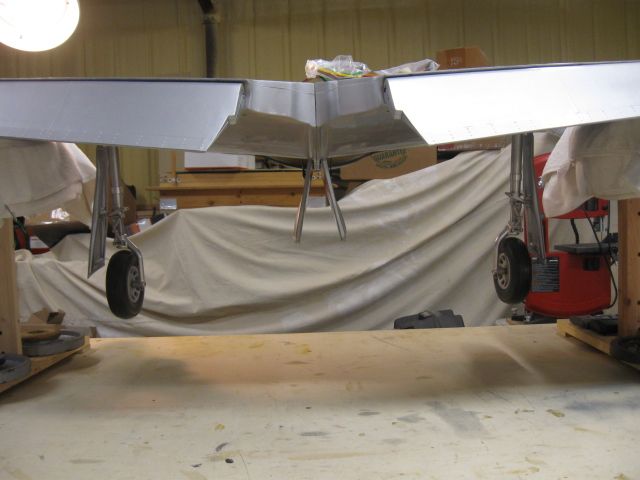
Perspective view.
Flaps up, gear down.
Perspective view, gear down.
Elevated view, full flaps down.
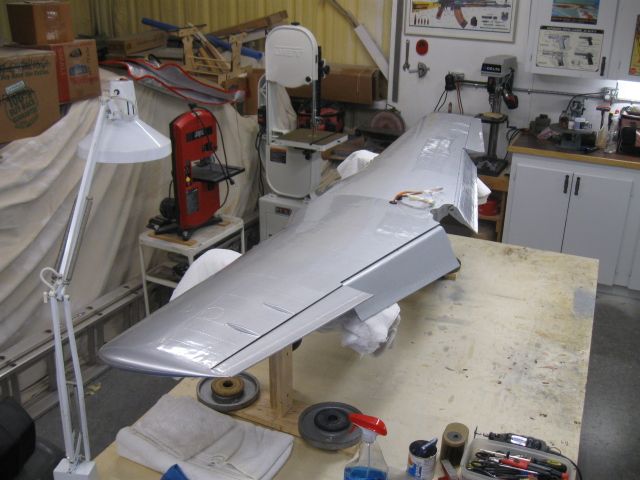
Exit holes for servo leads and air lines.
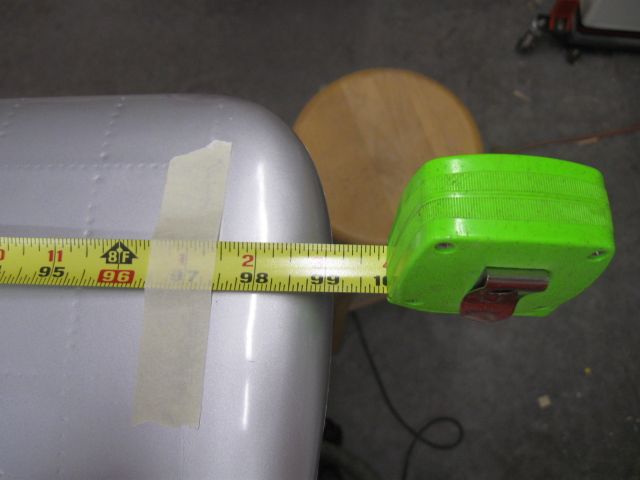
Now, the big bomb - it's only 99 inches span! Not 100. ha
Fullest flaps down setting.
Perspective view.
Flaps up, gear down.
Perspective view, gear down.
Elevated view, full flaps down.
Exit holes for servo leads and air lines.
Now, the big bomb - it's only 99 inches span! Not 100. ha

 11-24-2016, 05:33 AM
#2372

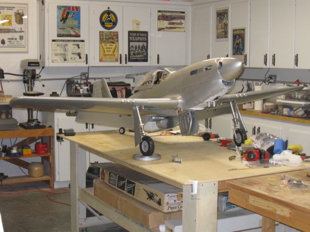
From the looks of it. The vertical fin is crooked also due to not having the balsa fin post inplace for the hinging of the rudder. Unless i'm just not seeing it in this blurry picture.
But i would think that is one of the issues there.
But i would think that is one of the issues there.
Last edited by Greg Wright; 11-25-2016 at 04:19 AM.
11-24-2016, 11:48 AM
#2374
To help solve this geometry problem your going to have to put the plane on a flat surface and measure it.
Square the fuse up on the table with the wing assembled tight. Make sure the wing tips or another surface is the same distance to the table. Then level the fuse lengthwise to the table. Once your comfortable with that then proceed to check the tips of the stab to the table. If they are within an 1/8 inch of each other then it's fine. You can check the fin for square to the table too.
This is a good way to get a clear picture on what's going on.
If you pick the stab area to work on the problem then the adjustment shifts to the wing saddle. Assuming the tail would be square to itself. I'm pretty sure you don't want to do that. So settle on the wing and fuse being OK and then see what's up with the tail. Once you see the whole picture you can determine the path to fixing it.
11-25-2016, 07:55 AM
#2375
My Feedback: (36)

Join Date: Jan 2002
Location: Poland, Maine
Posts: 512
Likes: 0
Received 0 Likes
on
0 Posts
Thanks Chris, I'll check it as you suggested, but I'm fairly sure the plane has a twist in the stab area,maybe installing the rudder post will fix, but not sure of that,never noticed it until I glued on the stab..