


KMP New Spitfire Mk XIV

 04-11-2014, 05:17 AM
#1278
Senior Member
My Feedback: (4)

Join Date: Aug 2008
Location: EllinikoAthens, GREECE
Posts: 1,079
Likes: 0
Received 5 Likes
on
5 Posts
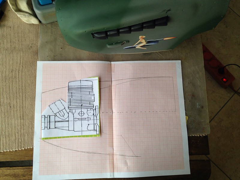
Engine choice is a nice European Airworld Moki 30cc, front carb, compact and powerful: http://www.airworld.online.de/Englis...i_30/index.htm
These are available in the UK from Stuart Mackay and the US from Vogelsang AeroScale
http://www.vogelsang-aeroscale.com/moki.html

These are available in the UK from Stuart Mackay and the US from Vogelsang AeroScale
http://www.vogelsang-aeroscale.com/moki.html
Last edited by w1nd6urfa; 04-11-2014 at 05:32 AM.
 04-11-2014, 05:28 AM
#1282
Senior Member
My Feedback: (4)
Join Date: Aug 2008
Location: EllinikoAthens, GREECE
Posts: 1,079
Likes: 0
Received 5 Likes
on
5 Posts
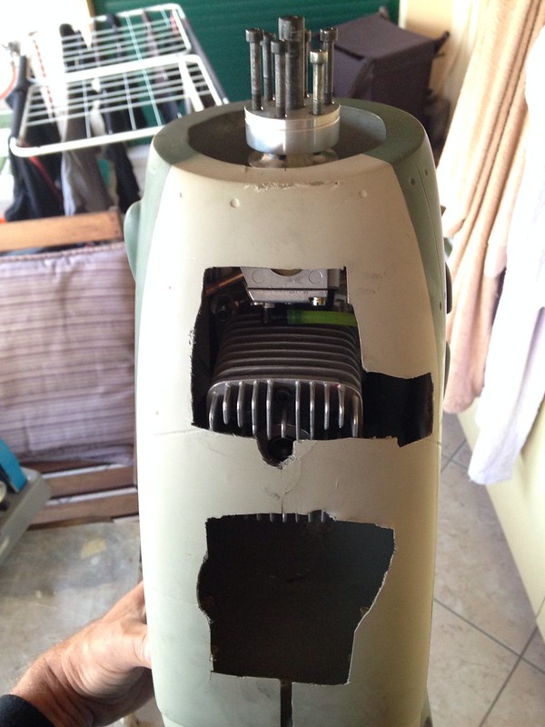
The outcome is quite good, the plug and muffler pipe will be protruding.
I will make some air inlets, baffle around the cylinder fins and hot air outlet grilles later on
I will make some air inlets, baffle around the cylinder fins and hot air outlet grilles later on
04-11-2014, 06:23 AM
#1283

Join Date: Dec 2003
Location: manchester, AE, UNITED KINGDOM
Posts: 1,795
Likes: 0
Received 0 Likes
on
0 Posts
Finally finished skimming over this whole thread.. wow, kind of numb now..
Well, I would think from your descriptions, I have the first version. It has the large sticker/decal sheet, the fuselage and cowl is fiberglass, one piece horizontal stab. Not certain about the retracts, if they are air up/down, or the air up spring down without testing.. Im not a big fan of spring air, but they are somewhat more fail safe.. but with restrictors they should be alright.
As I said though, everything is still in the sealed packages, in fact the packages were still hot glued to the box. One wing panel was open, so I have removed that panel and did a quick look.
Are there things that I should be aware of when building, like weak areas etc?
Thanks for the response alanc
a lot complained about the hardware, i have to say now, that i ditched some, and used other parts, i used the plastic horns, and the clevises, no problems, i found that things like retaining collars, for wheels, had bad threads, tapped out at odd angles, simple enough to replace, the tank i used, but with another bung, the designer, Ian Redshaw, used an RCV 90 cd 4 stroke, it was ample power, but others use much more, only thing i thought this model needed, was more dihedral, but thats a personal want, just does not look right, i also, when building, replaced the wing spar, with something cut out of marine ply, it just felt soft,
It flies great, just watch the nose overs, it was prone for this, hence the rake the gear forward, and use a set of oleos legs, NOT the wire, use dual rates on elevator, with lots of expo, switch to full rate on landing, and use the expo, just dont forget its there, its not something i would like to use when flying, but it does keep the tail down on roll out,
04-11-2014, 06:47 AM
#1284
Senior Member
My Feedback: (1)
Join Date: Jul 2010
Location: Eugene, OR
Posts: 457
Likes: 0
Received 0 Likes
on
0 Posts
Thanks again alanc I am a competent builder, so there should be no real problem building the plane strong, but it helps having any awareness of what to look for, rather than just finding out after the fact 
It seems a shame that these are not produced anymore, as they are very well built kits from what I have noticed so far. Of course, with anything pre built, you will always have people that like it, and others that think otherwise. Some are capable of knowing where to strengthen areas, and some that have no idea.. that is the way of the world, in that you can never please everyone.
I have yet to take photo's, but I intend on doing so before I get started. Id just like to say that you had produced a very nice kit. Even with the years it has sat in the box, everything is in very good condition. The covering is still holding good with only a couple areas around the edges that will need to be tacked with the heating iron.
hmm, you guys think that my GP 61cc would be too much for this thing?? im kidding!
If you were closer to me, being you were the developer (or designer?) I would consider offering the kit to you, but I seriously do not think I really could let this thing go! I have been wanting to build a Spitfire for quite some time. The only thing that would make it better to me is if it was closer to a 50-60cc size. But not complaining!
I am a competent builder, so there should be no real problem building the plane strong, but it helps having any awareness of what to look for, rather than just finding out after the fact It seems a shame that these are not produced anymore, as they are very well built kits from what I have noticed so far. Of course, with anything pre built, you will always have people that like it, and others that think otherwise. Some are capable of knowing where to strengthen areas, and some that have no idea.. that is the way of the world, in that you can never please everyone.
I have yet to take photo's, but I intend on doing so before I get started. Id just like to say that you had produced a very nice kit. Even with the years it has sat in the box, everything is in very good condition. The covering is still holding good with only a couple areas around the edges that will need to be tacked with the heating iron.
hmm, you guys think that my GP 61cc would be too much for this thing??
im kidding! If you were closer to me, being you were the developer (or designer?) I would consider offering the kit to you, but I seriously do not think I really could let this thing go! I have been wanting to build a Spitfire for quite some time. The only thing that would make it better to me is if it was closer to a 50-60cc size. But not complaining!
04-11-2014, 06:55 AM
#1285
Senior Member
My Feedback: (1)
Join Date: Jul 2010
Location: Eugene, OR
Posts: 457
Likes: 0
Received 0 Likes
on
0 Posts
w1nd6urfa, your repairs are looking really good
I know people that toss less damaged airframes in the bin Good luck with the rest, and hope you get many more flights of enjoyment out of it!
I know people that toss less damaged airframes in the bin
Good luck with the rest, and hope you get many more flights of enjoyment out of it!
04-11-2014, 09:23 AM
#1286
Join Date: Dec 2003
Location: manchester, AE, UNITED KINGDOM
Posts: 1,795
Likes: 0
Received 0 Likes
on
0 Posts
I am not the designer, my mate Ian is, I worked with YT international, We sort of helped the factory to grow, The early offerings were a tad poor in shape, Our first was the hurricane, We followed with the spitfire you have, Once the factory learned, they went on their own way, The rest is history, now, YT is just another importer, like Kmp, I am no longer with them, I have sort of semi retired, but I still see the guys at shows, and still have several esm birds, Enjoy your model, It flys very well, If you look on the YT site, you may even find vid of the prototype flying, I must say, I read a lot about the esm range on here, and see some of the engines you guys fit, It, erm, amuses me, The biggest engine I have heard fitted into the original hurricane, at 72" was, would you believe. A DA50!!!!!!!!
04-11-2014, 07:39 PM
#1288
Senior Member
My Feedback: (4)
Join Date: Aug 2008
Location: EllinikoAthens, GREECE
Posts: 1,079
Likes: 0
Received 5 Likes
on
5 Posts
I know, I have picked several such kits that were built without any mods and after a couple of flights started to come apart. I get a strange kick out of fixing them rather than buying new

I kind of like the v1 Spit paint scheme better, not very fond of stripes. Good luck with your build, post lots of photos.
Alan, this is a Mk XIV Spit, not a Fieseler Storch - its meant to be overpowered!
I have a CMP 109 running a DLE 20, flies very scale but I kept getting my b@tt kicked by overpowered Mustangs so enough is enough with scale speeds!
http://www.rcuniverse.com/forum/rc-w...l#post11478808
04-11-2014, 08:22 PM
#1289
Senior Member
My Feedback: (1)
Join Date: Jul 2010
Location: Eugene, OR
Posts: 457
Likes: 0
Received 0 Likes
on
0 Posts
Graham
I know, I have picked several such kits that were built without any mods and after a couple of flights started to come apart. I get a strange kick out of fixing them rather than buying new
I kind of like the v1 Spit paint scheme better, not very fond of stripes. Good luck with your build, post lots of photos.
Alan, this is a Mk XIV Spit, not a Fieseler Storch - its meant to be overpowered!
I have a CMP 109 running a DLE 20, flies very scale but I kept getting my b@tt kicked by overpowered Mustangs so enough is enough with scale speeds!
http://www.rcuniverse.com/forum/rc-w...l#post11478808
And yeah, I will be posting pictures of the build, absolutely!
04-12-2014, 04:26 PM
#1290
Senior Member
My Feedback: (1)
Join Date: Jul 2010
Location: Eugene, OR
Posts: 457
Likes: 0
Received 0 Likes
on
0 Posts
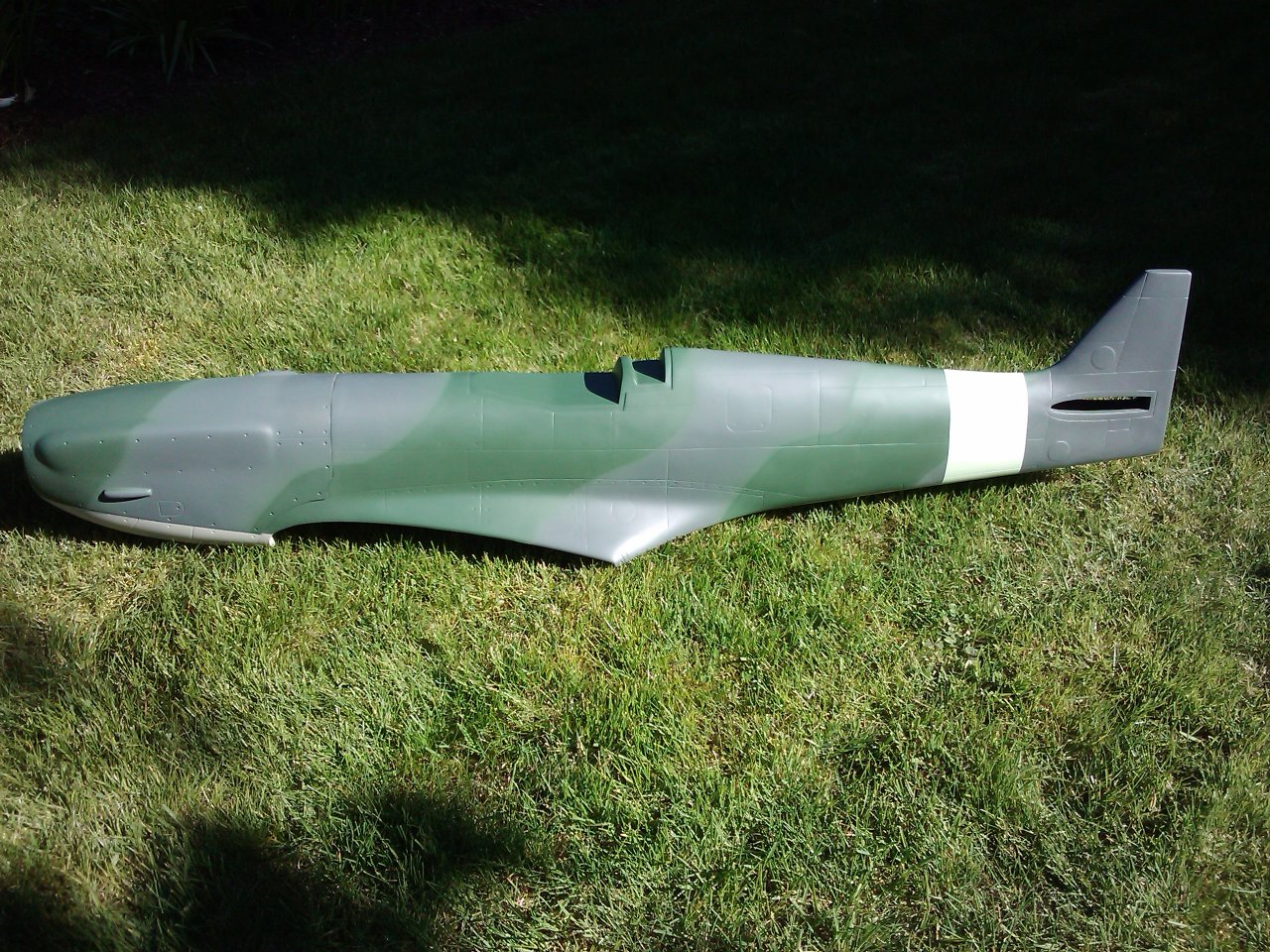
So here is the plane fresh from the sealed packages. So far I have not found anything to speak of that looks damaged or defective


04-13-2014, 12:35 AM
#1291
Join Date: Dec 2003
Location: manchester, AE, UNITED KINGDOM
Posts: 1,795
Likes: 0
Received 0 Likes
on
0 Posts
Thats the first version, be carefull cutting the plastic parts, they are brittle, the radiators need reinfocement, i glass the inside of mine, i have wondered with this brittle plastic, if dropping in boiling water will temper the plastic, have a go at a scrap piece, let me know!!! i also used an internal elevator joiner, bought from all places, brodak, the controline line guys, they do various shapes and sizes, well, they did, it wasa while ago, single pushrod down the middle, with 3 mm ball link, i actuall get the servos way up front, and run a link to a bellcrank, then from the crank to the elevator, the rudder i use closed loop, pull pull to you guys, i do the same with this, servo up front, to a bellcrank, and bin those plastic wells, i sheeted mine with 1/64 ply and balsa, easy to do, and look SO much better,
04-13-2014, 05:18 PM
#1292

Join Date: Apr 2007
Location: Qld, AUSTRALIA
Posts: 309
Likes: 0
Received 0 Likes
on
0 Posts
hi,
I am in the process of building my second ESM Spit, as others have said, rake the undercarriage forward, I also moved my fuel tank back, so it is over the CofG, also helps with the ground handling, I used Pull, Pull for the Rudder, but I run 2 servos with CFibre push rods for the Elevators.
to line up my Engine, I stand the Fuselage on its tail against the bench, sit the engine on the Firewall, put the pre fitted Cowl over the top, put the Spinner Back Plate in place, move the engine around until the Spinner lines up with the Cowl, mark the mount points and drill, all lined up. easy. (I read it somewhere else) but it works.
to fit the Wing Dowels, I mark the Fuselage wing saddle where they should be, then drill right through into the engine bay, fit the Wing in place, back drill into the wing, all lined up.
the wing on both kits wasnt a good fit as to the Square lined up, so check that. Give it as much Flap travel as you can, it makes a difference on landing. I balanced mine at about 100 mm back from the Centre join, took heaps of lead to balance, but I think it makes a difference to the way the model flies and landings are nicer.
beautiful model, looks fantastic in the air, it is a Spitfire.
Oldtimer
04-13-2014, 05:52 PM
#1293
Senior Member
My Feedback: (1)
Join Date: Jul 2010
Location: Eugene, OR
Posts: 457
Likes: 0
Received 0 Likes
on
0 Posts
Thanks a lot for the tips, they will help.. But this is not my first build Been at it for over 30 years.. thats not to say I have nothing left to learn or am the best out there!
My only concern is detail.. I am not the most knowledgeable with war birds, so I have the fear of getting it done and having people that know all about spitfire's pick it apart, and ask me why I did this, or why I didn't do that.. or why is this color on there, etc! haha But I will do my best
Thanks for the input
Been at it for over 30 years.. thats not to say I have nothing left to learn or am the best out there!My only concern is detail.. I am not the most knowledgeable with war birds, so I have the fear of getting it done and having people that know all about spitfire's pick it apart, and ask me why I did this, or why I didn't do that.. or why is this color on there, etc! haha But I will do my best
Thanks for the input
04-15-2014, 10:23 AM
#1294
Senior Member
My Feedback: (4)
Join Date: Aug 2008
Location: EllinikoAthens, GREECE
Posts: 1,079
Likes: 0
Received 5 Likes
on
5 Posts
Guys,
I need your help here:
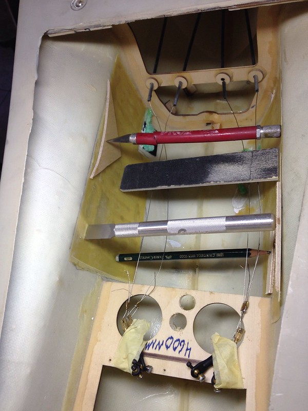
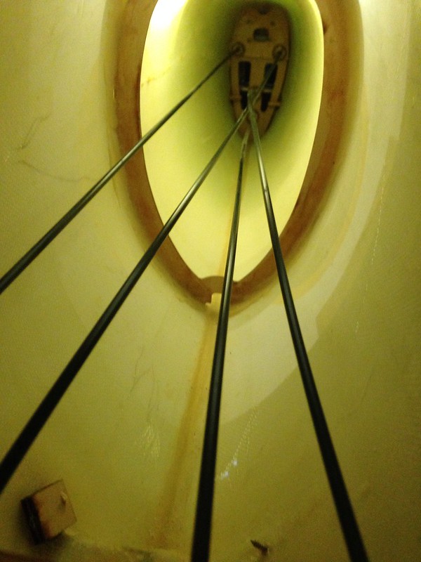
As I said I got this second hand, and as I was checking the pull-pull cables I noticed something strange: the bottom elevator cable tube crosses over the starboard rudder cable tube and forms an arc!
That looks strange because if I tighten the elevator cable it pulls the rudder cable
Can you please check your plane and advise if this is correct?
Attached pic the fuse is upside-down
https://www.flickr.com/photos/109944463@N07/13876072815
I need your help here:
As I said I got this second hand, and as I was checking the pull-pull cables I noticed something strange: the bottom elevator cable tube crosses over the starboard rudder cable tube and forms an arc!
That looks strange because if I tighten the elevator cable it pulls the rudder cable
Can you please check your plane and advise if this is correct?
Attached pic the fuse is upside-down
https://www.flickr.com/photos/109944463@N07/13876072815
04-15-2014, 10:36 AM
#1295
Senior Member
My Feedback: (1)
Join Date: Jul 2010
Location: Eugene, OR
Posts: 457
Likes: 0
Received 0 Likes
on
0 Posts
Yeah, I would not be comfortable using that setup, personally. Looks like you are going to have to break that one out and re route it, or if you are able, maybe you could just rotate it up and back under from the front servo end. Second look seems that it had just wrapped around once and went unnoticed.
04-15-2014, 11:07 AM
#1297
Senior Member
My Feedback: (1)
Join Date: Jul 2010
Location: Eugene, OR
Posts: 457
Likes: 0
Received 0 Likes
on
0 Posts
Mine is a version 1 yes, however I have not installed any control rod's or cables yet. I will more than likely install pushrod's on the elevator and pull-pull or closed loop on the rudder as I typically do.
The elevator control rods I plan to use will be independent rod's per elevator half rather than coupling them together, as I like the ability to adjust them, where if they are connected together, if they are not absolutely true to each other, you are stuck with that.
The pull-pull for elevator is very precise and effective, but a much more difficult way to set up, and as you have found, hard to install in a way to allow each cable to be free from the others.
04-15-2014, 12:00 PM
#1298
My Feedback: (4)

Join Date: Jan 2002
Location: Prague, CZECH REPUBLIC
Posts: 4,144
Likes: 0
Received 0 Likes
on
0 Posts
Hi JRg, I would be interested in seeing some pictures of your install when done. It sounds like a logical option. Thanks.
Cheers, V.
Cheers, V.
Mine is a version 1 yes, however I have not installed any control rod's or cables yet. I will more than likely install pushrod's on the elevator and pull-pull or closed loop on the rudder as I typically do.
The elevator control rods I plan to use will be independent rod's per elevator half rather than coupling them together, as I like the ability to adjust them, where if they are connected together, if they are not absolutely true to each other, you are stuck with that.
The pull-pull for elevator is very precise and effective, but a much more difficult way to set up, and as you have found, hard to install in a way to allow each cable to be free from the others.
The elevator control rods I plan to use will be independent rod's per elevator half rather than coupling them together, as I like the ability to adjust them, where if they are connected together, if they are not absolutely true to each other, you are stuck with that.
The pull-pull for elevator is very precise and effective, but a much more difficult way to set up, and as you have found, hard to install in a way to allow each cable to be free from the others.
04-15-2014, 12:16 PM
#1299
Senior Member
My Feedback: (1)
Join Date: Jul 2010
Location: Eugene, OR
Posts: 457
Likes: 0
Received 0 Likes
on
0 Posts
I do intend on posting images as I build the spitfire. In the mean time, I will see if I can find a couple pushrod options that I am talking about and post them.
One of the best methods is to use Carbon rods. You would use two rods per elevator half, and one rod would be solid for the actual pushrod with the clevis ends, the other would be a hollow carbon tube that the first solid carbon rod would just fit inside, similar to the sullivan golden rod setup. When done right, there is absolutely no flex or slop beyond whatever you might get from the servo. That is the best of the best, really, and you can use much smaller diameter rods than the sullivanor arrow shafts typically used.
One of the best methods is to use Carbon rods. You would use two rods per elevator half, and one rod would be solid for the actual pushrod with the clevis ends, the other would be a hollow carbon tube that the first solid carbon rod would just fit inside, similar to the sullivan golden rod setup. When done right, there is absolutely no flex or slop beyond whatever you might get from the servo. That is the best of the best, really, and you can use much smaller diameter rods than the sullivanor arrow shafts typically used.
04-15-2014, 12:24 PM
#1300
Senior Member
My Feedback: (1)
Join Date: Jul 2010
Location: Eugene, OR
Posts: 457
Likes: 0
Received 0 Likes
on
0 Posts
Okay, here is what I just explained, and a very good price for the package.
http://www.centralhobbies.com/contro...age/deps1.html
Here is a very good How-To guide in setting this type of split elevator push rod setup, and some images along the way..
http://www.centralhobbies.com/instru.../depsinst.html
They are fairly popular to setup with the pattern planes, but any plane you want to have precision with should consider this setup.