


8th Scale Aviation's, "CzechMate" Short-kit, Group build


")
 05-16-2016, 09:30 PM
#228

Thread Starter

Sorry it has taken so long for me to answer your question, but life has been a bit hectic for Tim and I, lately. We've only met twice for the build in nearly two months, and I haven't even been able to make time to keep up on posting the progress we have actually made, to date.
To answer your question, we will reinforce the joint holding the box in-place. But, beyond simply using epoxy alone, we will eventually reinforce this assembly by fiberglassing the joints.
05-16-2016, 09:44 PM
#229
Thread Starter
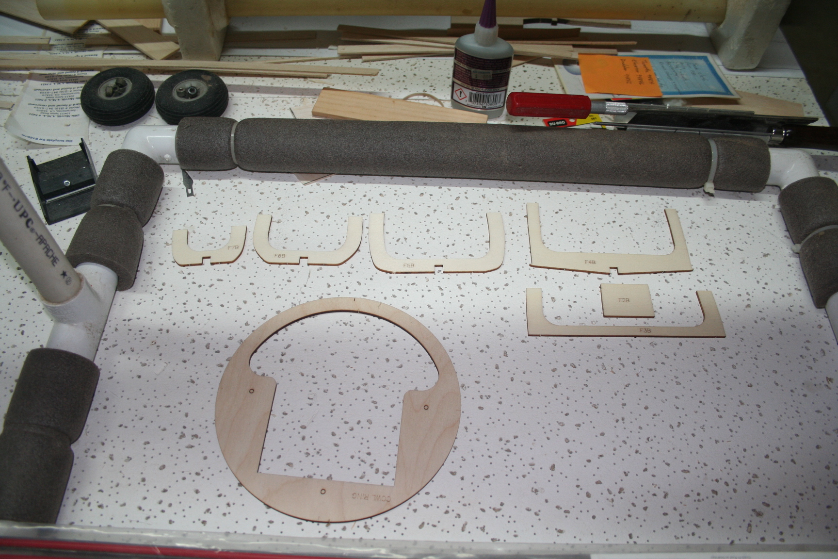
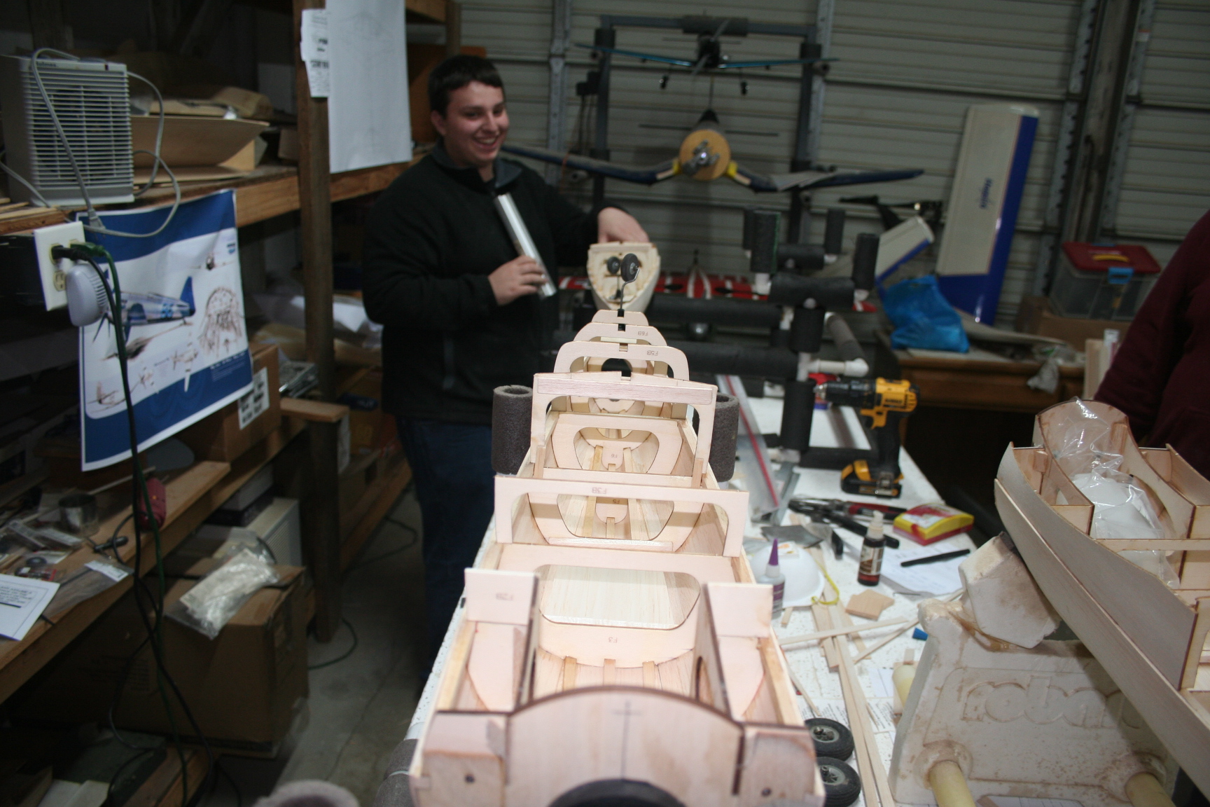
Next, it was time to add the formers to the lower section of the fuse. Each of us laid-out our bottom fuse formers (and the cowl ring is pictured, as well).
Tim inverts his fuse on the stand and gets started gluing each of the bottom formers squarely underneath the main fuse former above.
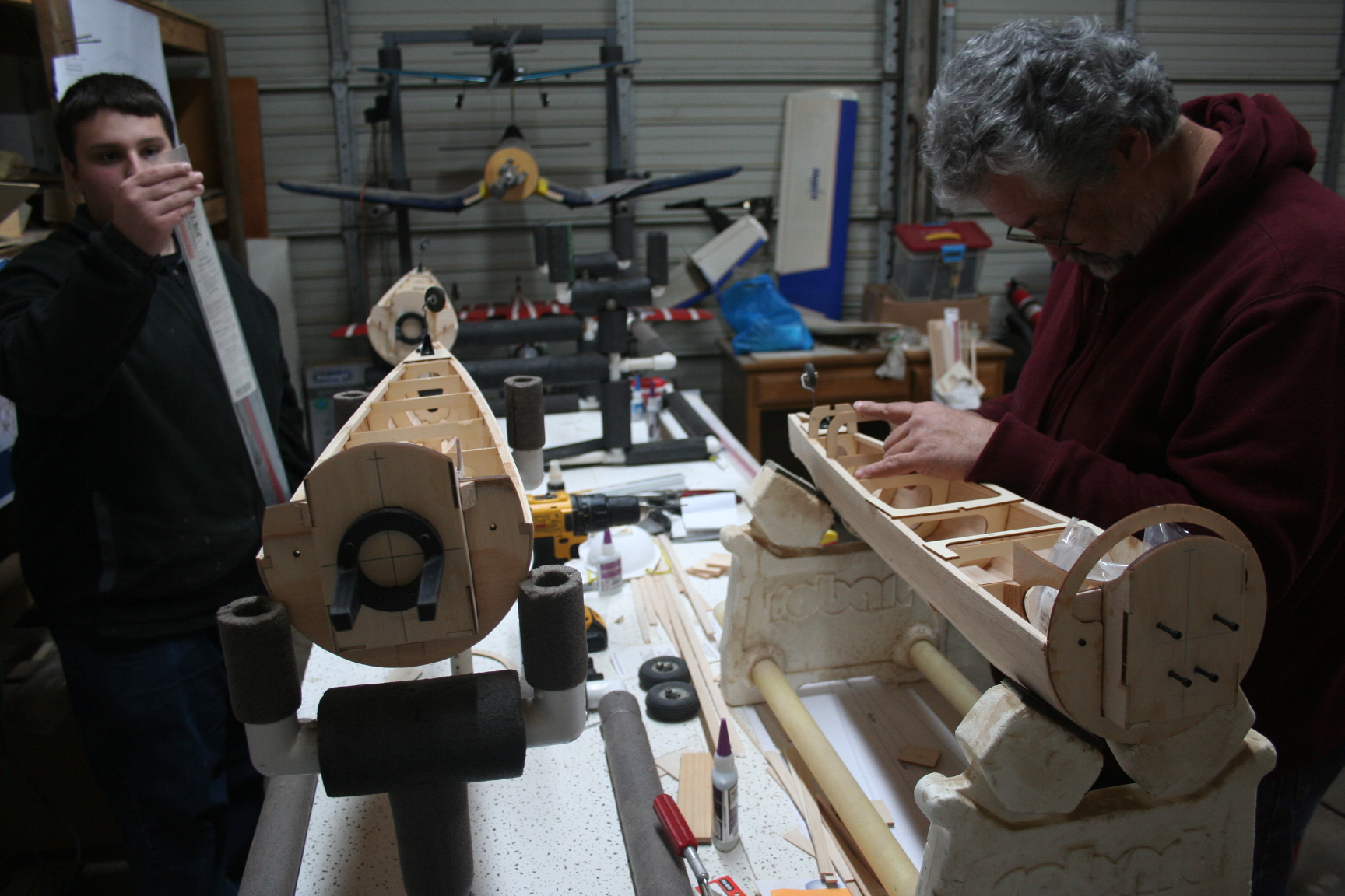
Tim inverts his fuse on the stand and gets started gluing each of the bottom formers squarely underneath the main fuse former above.
05-16-2016, 09:50 PM
#230
Thread Starter
Following suit, my formers are glued-in, as well (foreground), with Tim's completed in the background.
Eric works diligently to get his glued-in, as well.
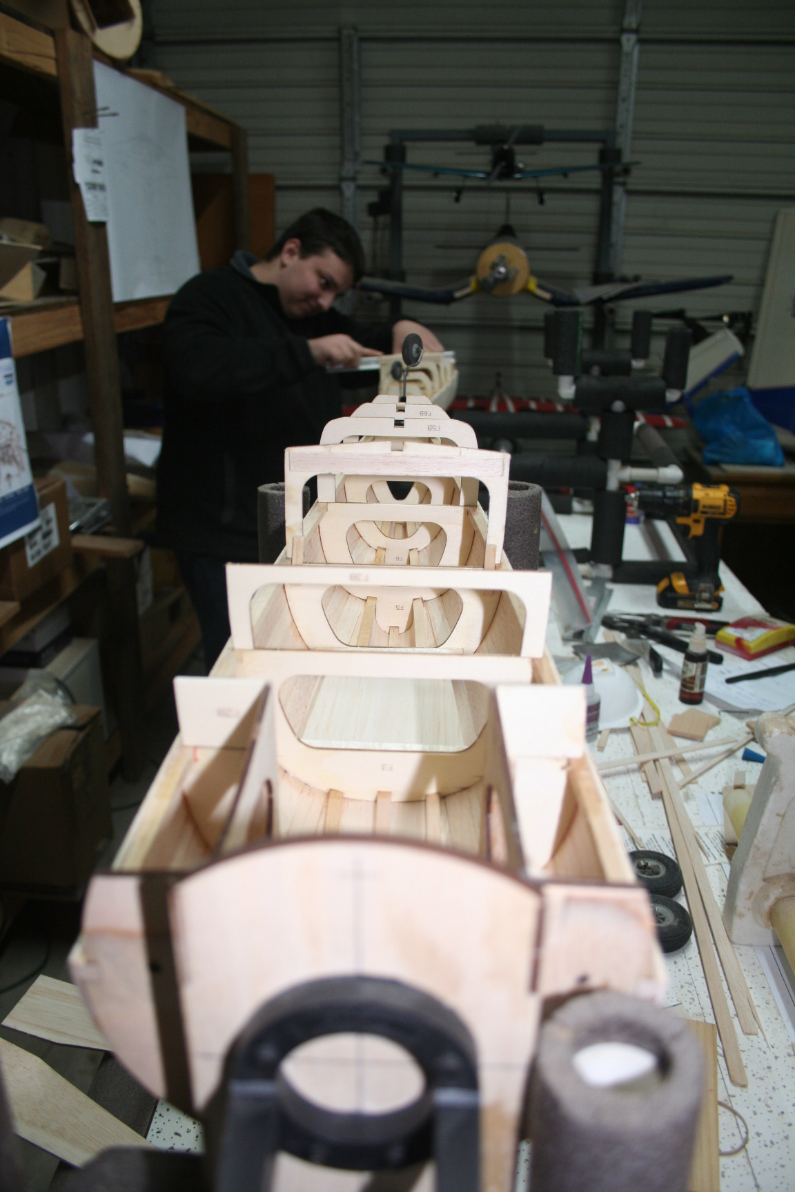
Eric works diligently to get his glued-in, as well.
05-16-2016, 10:07 PM
#232
Thread Starter
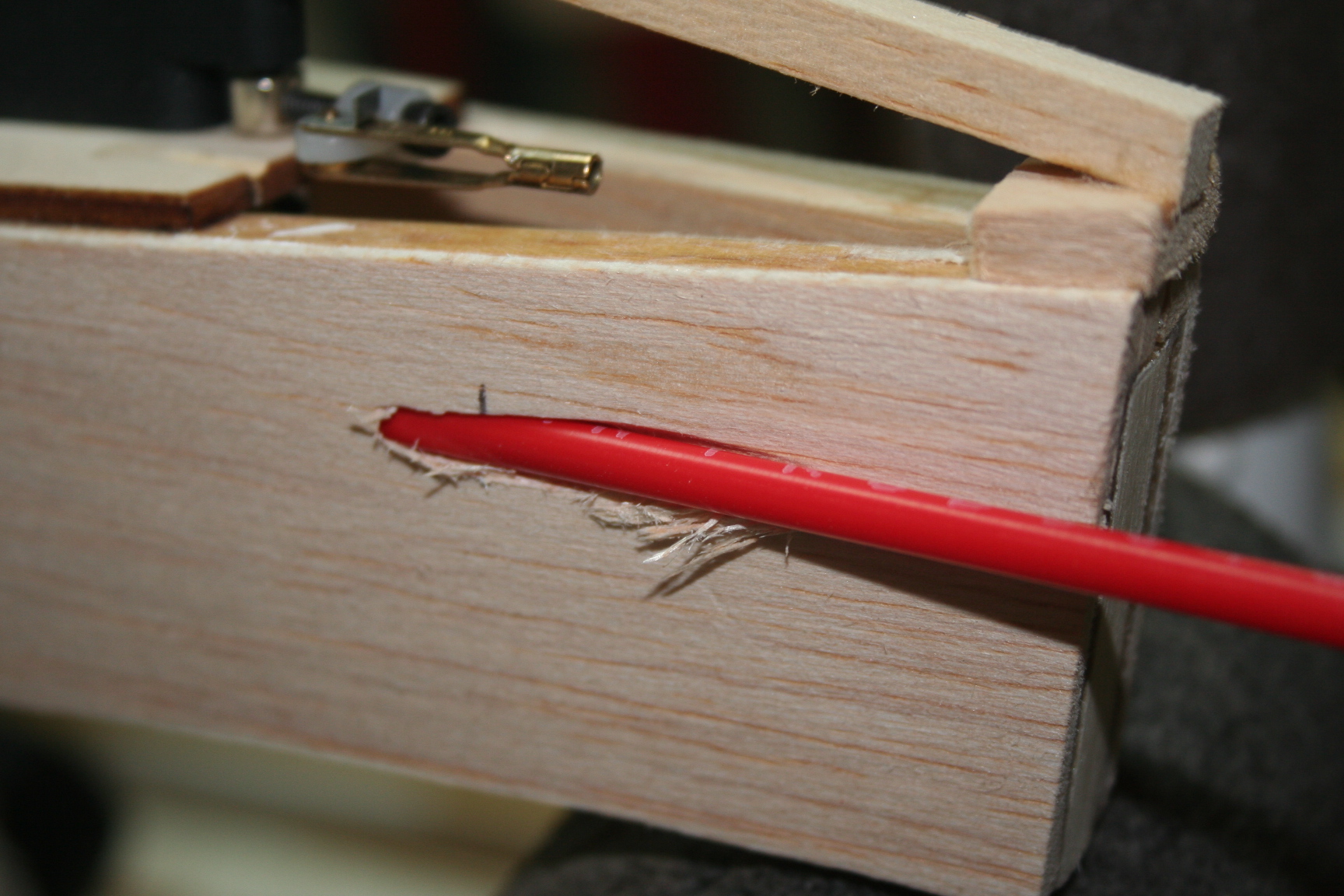
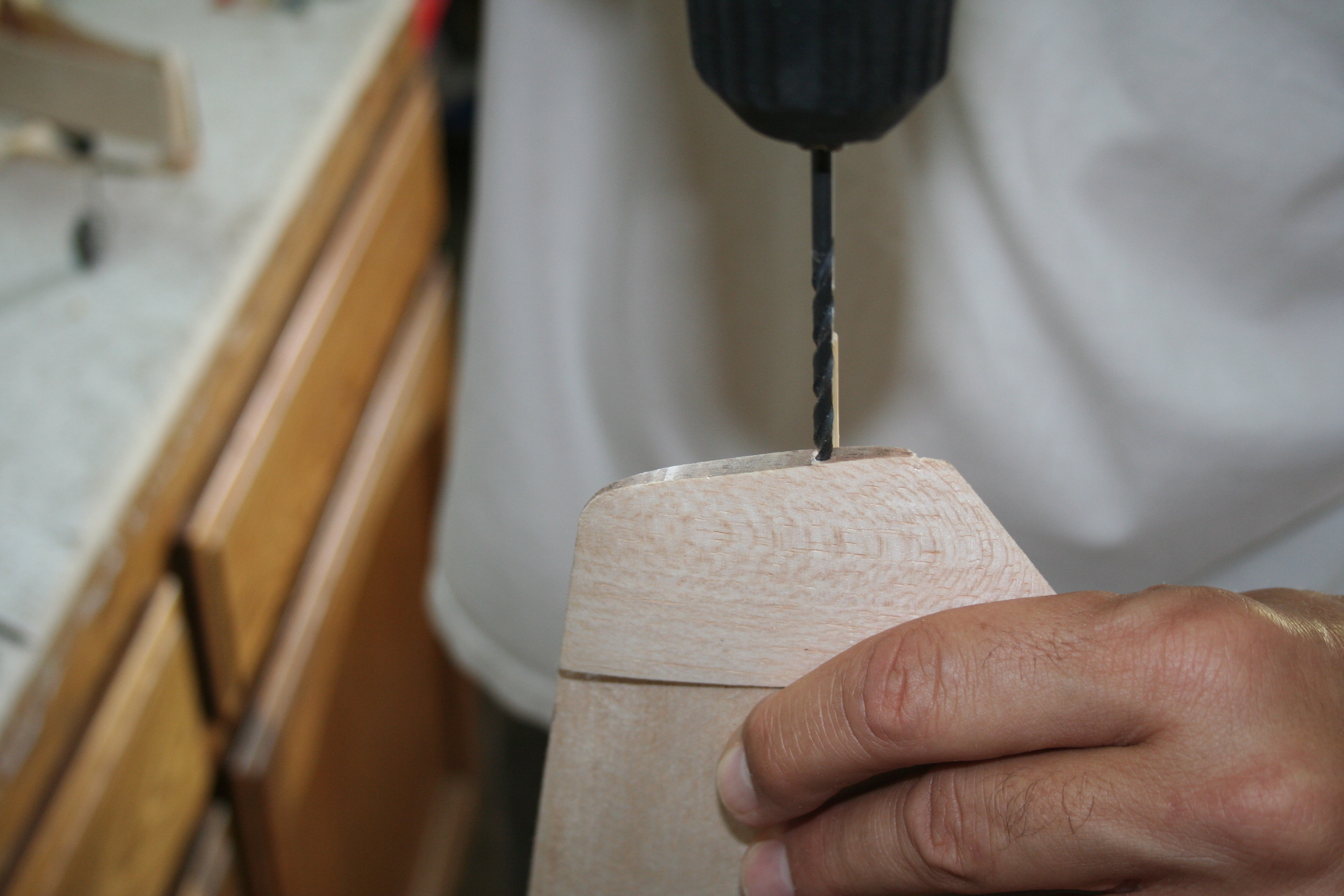
Now, Tim drills a "channel" in which to run the rudder control rod. This needs to be drilled on the same side as the tailwheel steering arm. I assist Tim by holding his fuselage tightly in-place, in its stand, as he drills through the starboard side of the fuse with an extra-long drill bit. Make sure to drill a path as straight as possible to the position of the rudder servo's output arm.
05-16-2016, 10:14 PM
#233
Thread Starter
The 1/4 x 1/4" balsa stringer is glued into place. It runs the length of the distance from the former at the trailing edge of the wing saddle, to just short of touching the tailwheel wire. Note that the stringer sits directly on top of the tailwheen mount.
05-16-2016, 10:26 PM
#234
Thread Starter
Cut a length of 1/4 x 1/4" stick to the length from the TE of the bottom rear fuse to just short of touching the rear of the tailwheel wire. To capture the scale curvature of the bottom rear fuse, glue this piece angled to match the more forward section of stringer. These two pieces are spliced using two shorter lengths (as pictured below), enclosing the area surrounding the tailwheel wire.
The rudder pushrod tube is inserted and glued in-place now, as well.
The rudder pushrod tube is inserted and glued in-place now, as well.
05-18-2016, 11:15 AM
#235
Hi "Flyer",
Sorry it has taken so long for me to answer your question, but life has been a bit hectic for Tim and I, lately. We've only met twice for the build in nearly two months, and I haven't even been able to make time to keep up on posting the progress we have actually made, to date.
To answer your question, we will reinforce the joint holding the box in-place. But, beyond simply using epoxy alone, we will eventually reinforce this assembly by fiberglassing the joints.
Flyer
On all these warbirds with a YS and high Nitro many if not all of us, reinforce every fire wall, whether it is an ARF or scratch built. On my Tsunami, I used tri stock, with 5 oz cloth and epoxy. I think because I run the bigger YS115 mine needs a bit more than , say a YS70 or 80, but those too need some reinforcing. Nothing worst than having it come loose on race day, when it is only a 10 minute fix in the shop to start with.

 05-20-2016, 06:43 PM
#237
Thread Starter
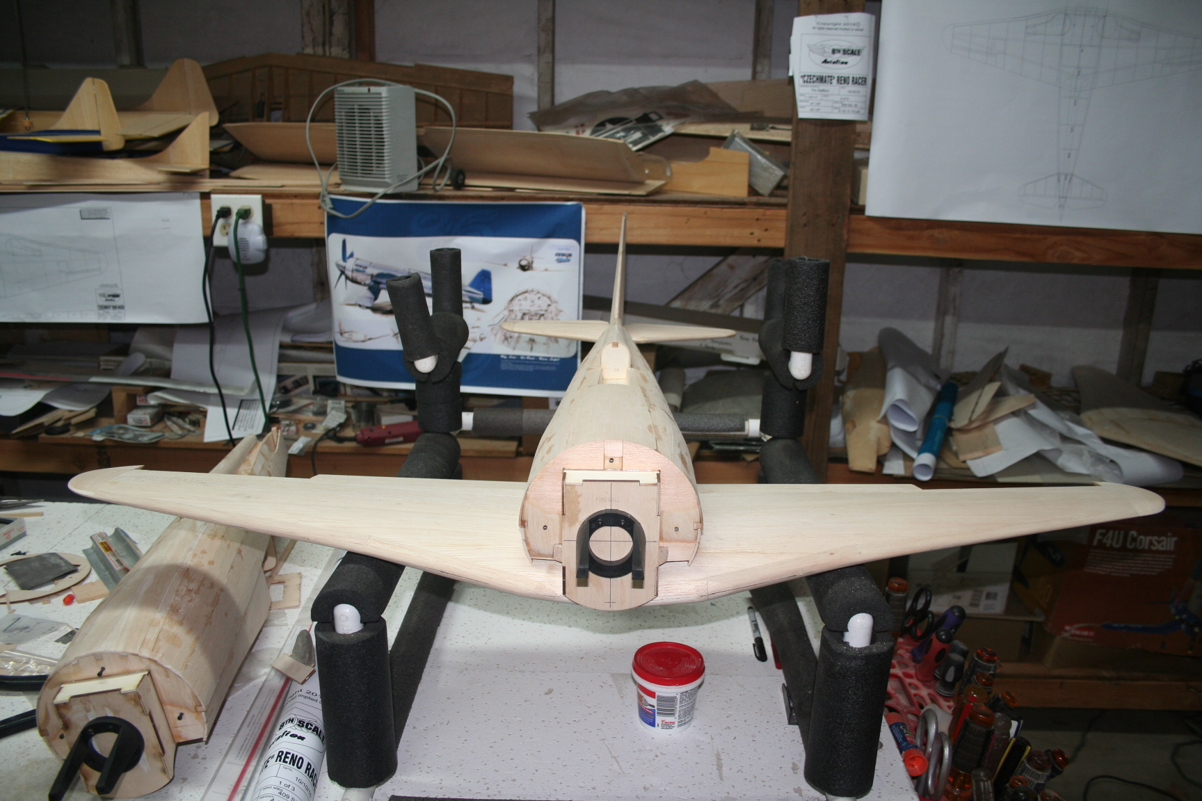
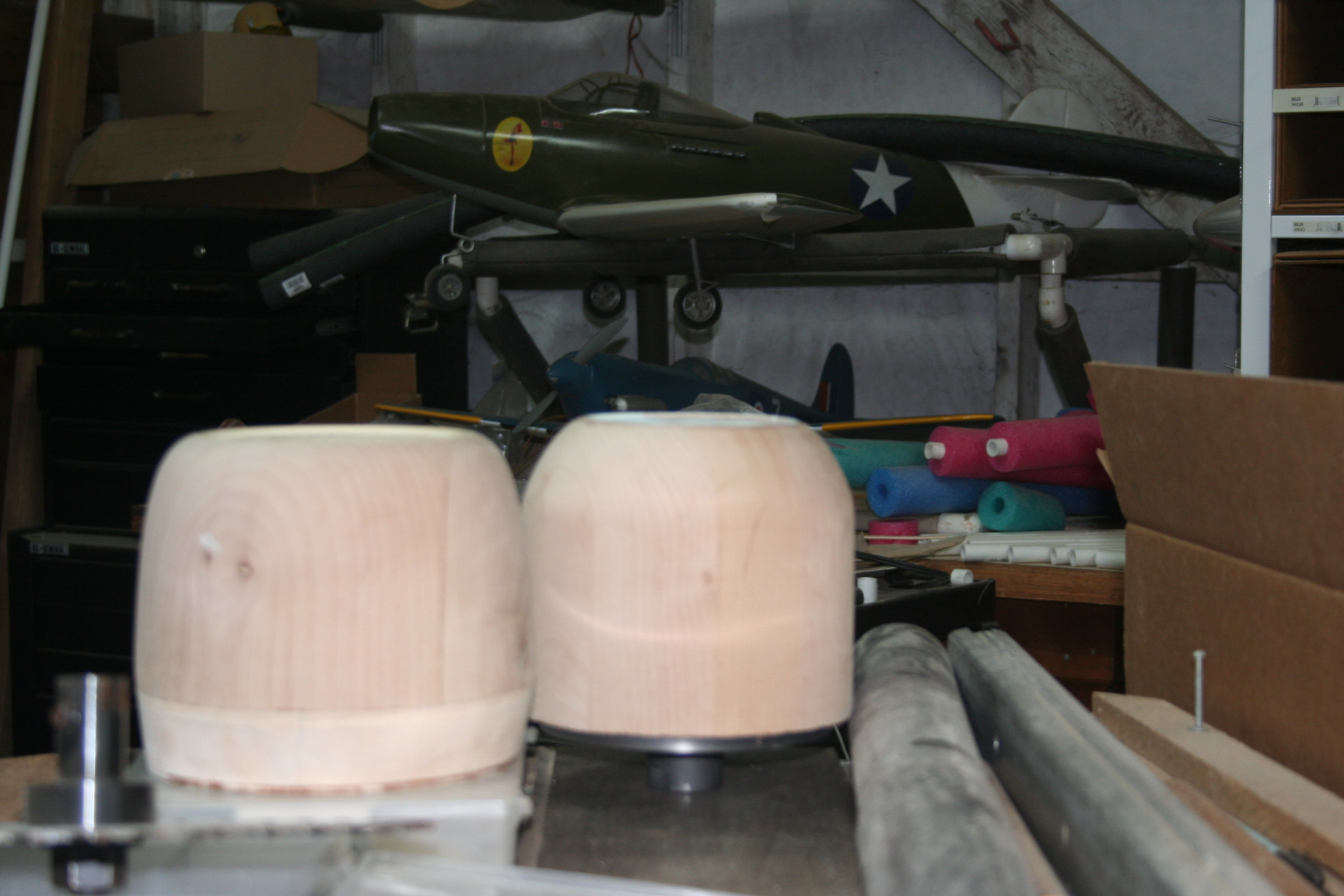
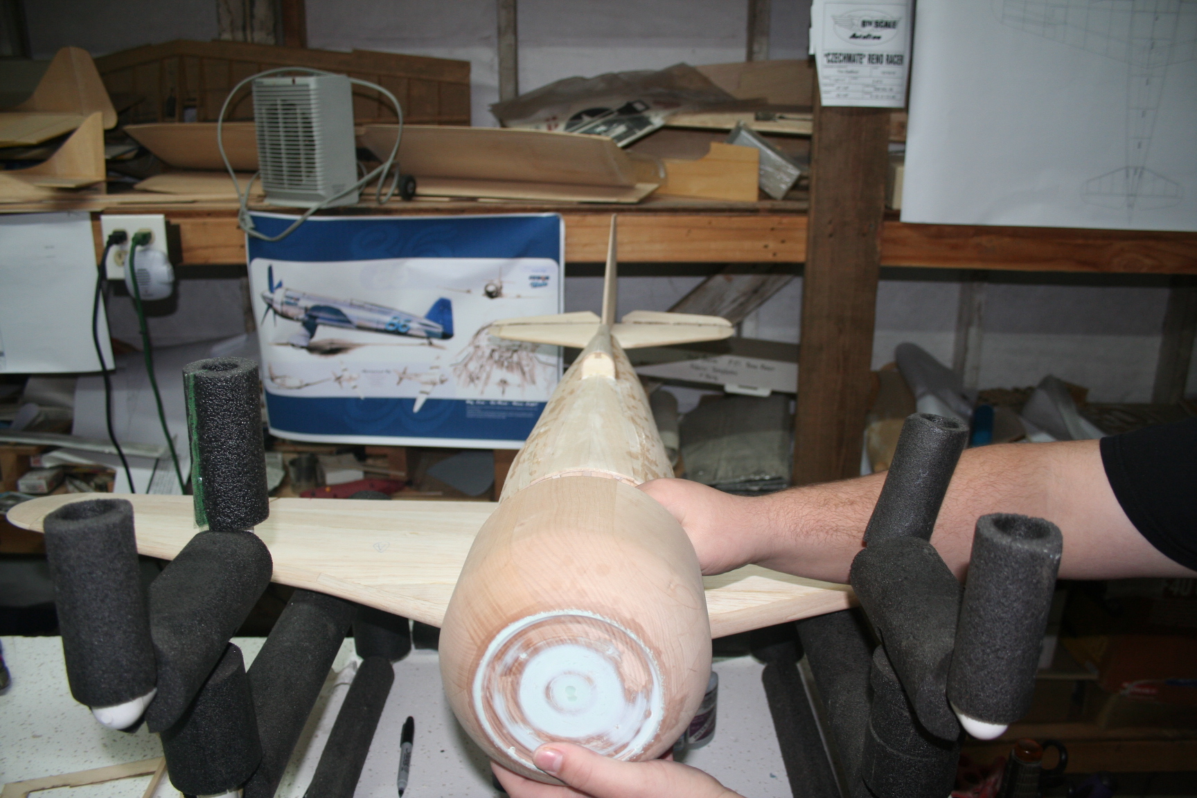
Following are the rest of the pictures I took during our build-day on March 13th. They show the tail feathers sittiing in the stab saddle, and the fuse at this stage of the build, sitting on the wing. we just wanted to get an idea of what the airplane was going to look like when actually done. Tim already posted pictures of the cowl plug after being finished; but the pictures below shoe what the plug looked like when it was still "rough." The two cowl plugs are for the Czechmeate (more rounded LE) and the Bearcat (less rounded LE) kits.
05-20-2016, 07:19 PM
#238
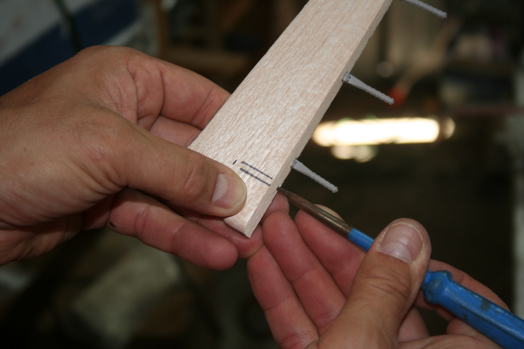
Thread Starter
On April 4th, we met again, and began working on the internal linkage for the elevator, Tim set a length of 3/32" music wire against a ruler and marked it at the 4 1/2" mark for all three of us. I then used a Dremel with a cut-off wheel to cut each of the 41/2" lengths.
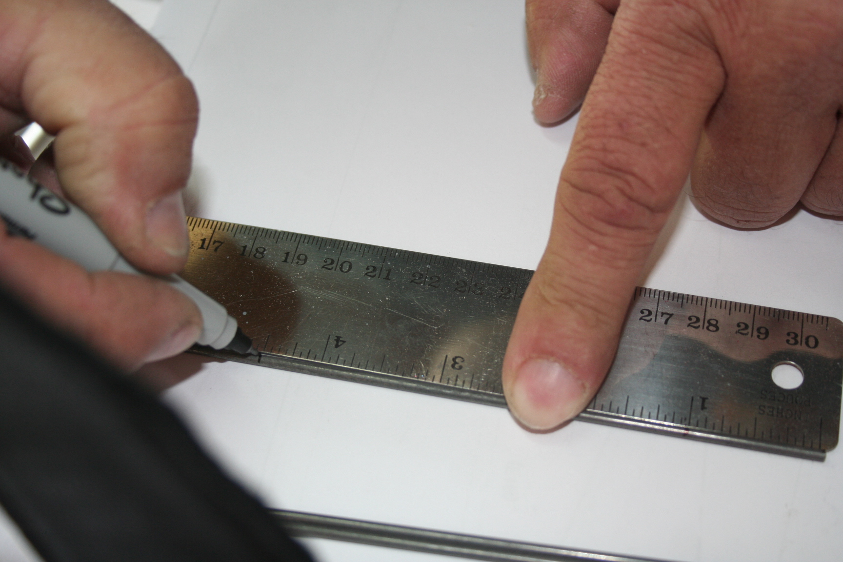
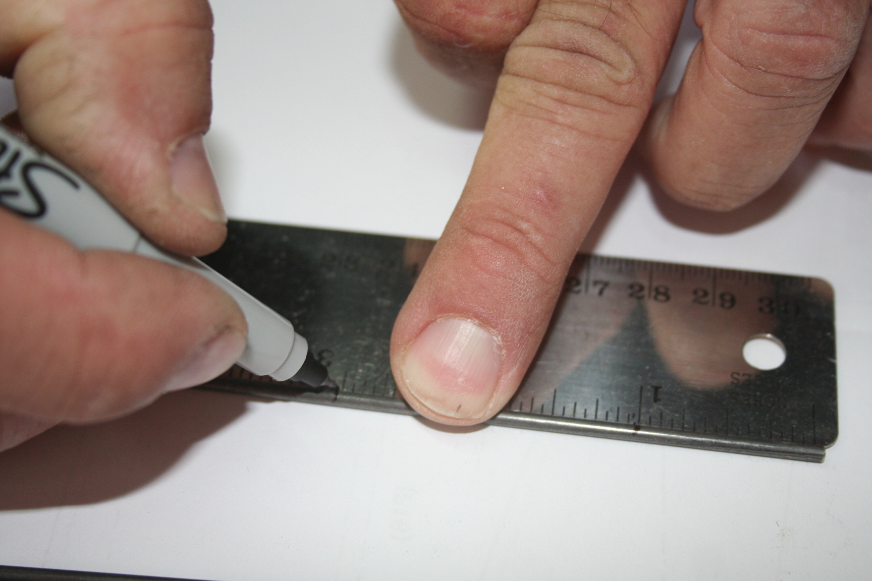
After each length was cut, it was again placed against the ruler, and marks were made 1" from each end.
At the 1"-in mark, one end of the wire is bent at 90 degrees, and two 3/32" wheel collars are slid onto the main length of the wire.

After each length was cut, it was again placed against the ruler, and marks were made 1" from each end.
At the 1"-in mark, one end of the wire is bent at 90 degrees, and two 3/32" wheel collars are slid onto the main length of the wire.
05-20-2016, 07:32 PM
#239
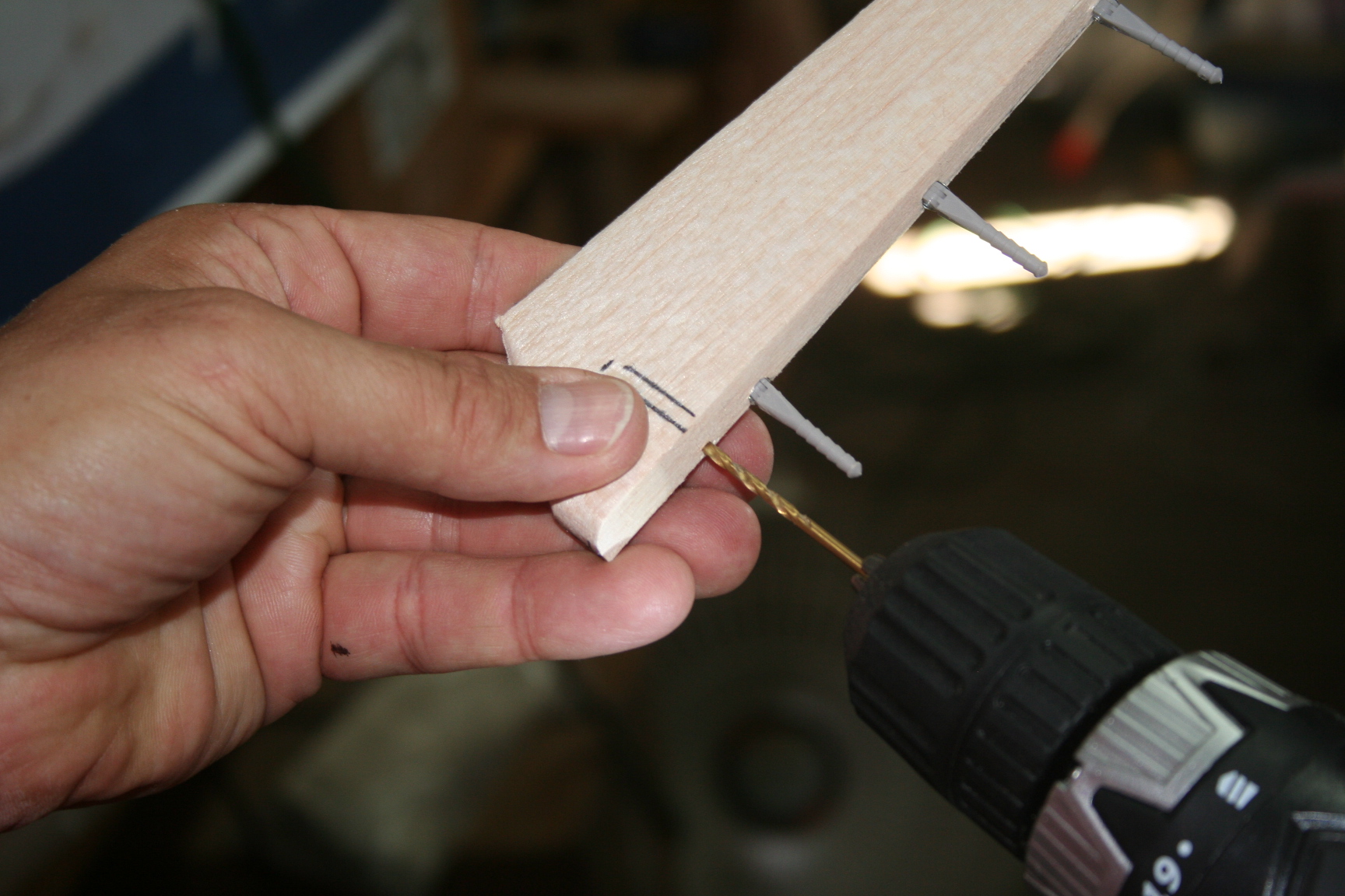
Thread Starter
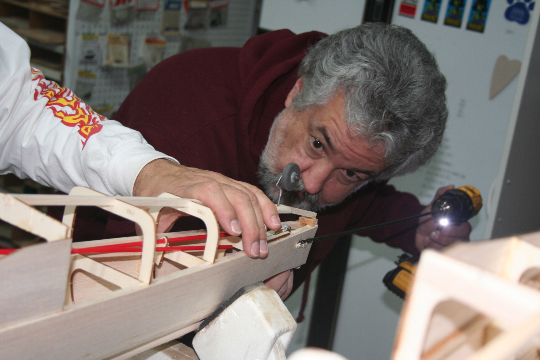
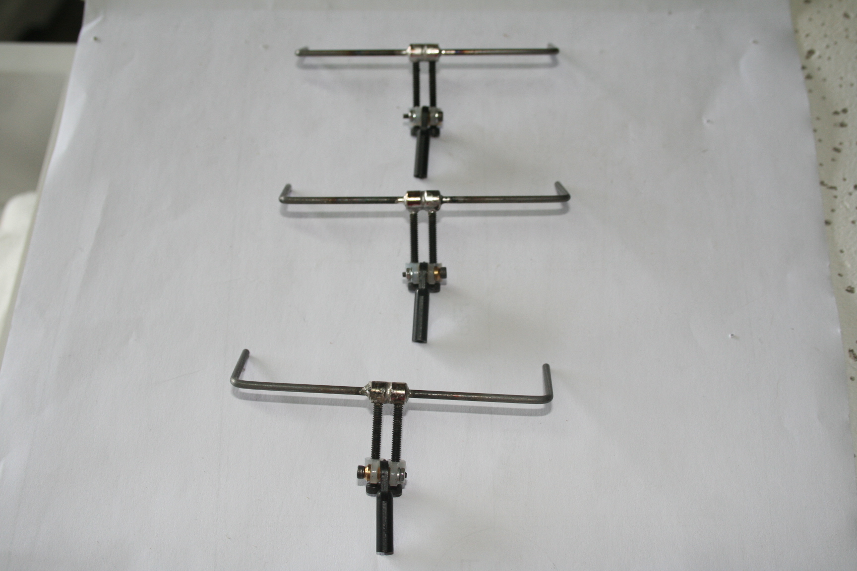
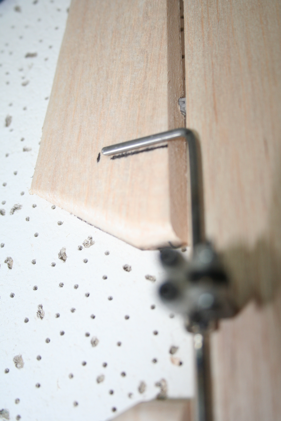
The other end of the elevator control wire is now bent 90 degrees at the other 1" mark. 3/32" EZ Control Horns are screwed all the way down the length of each 4-40 x 1" socket head bolt. Two of these are used for each elevator control wire.
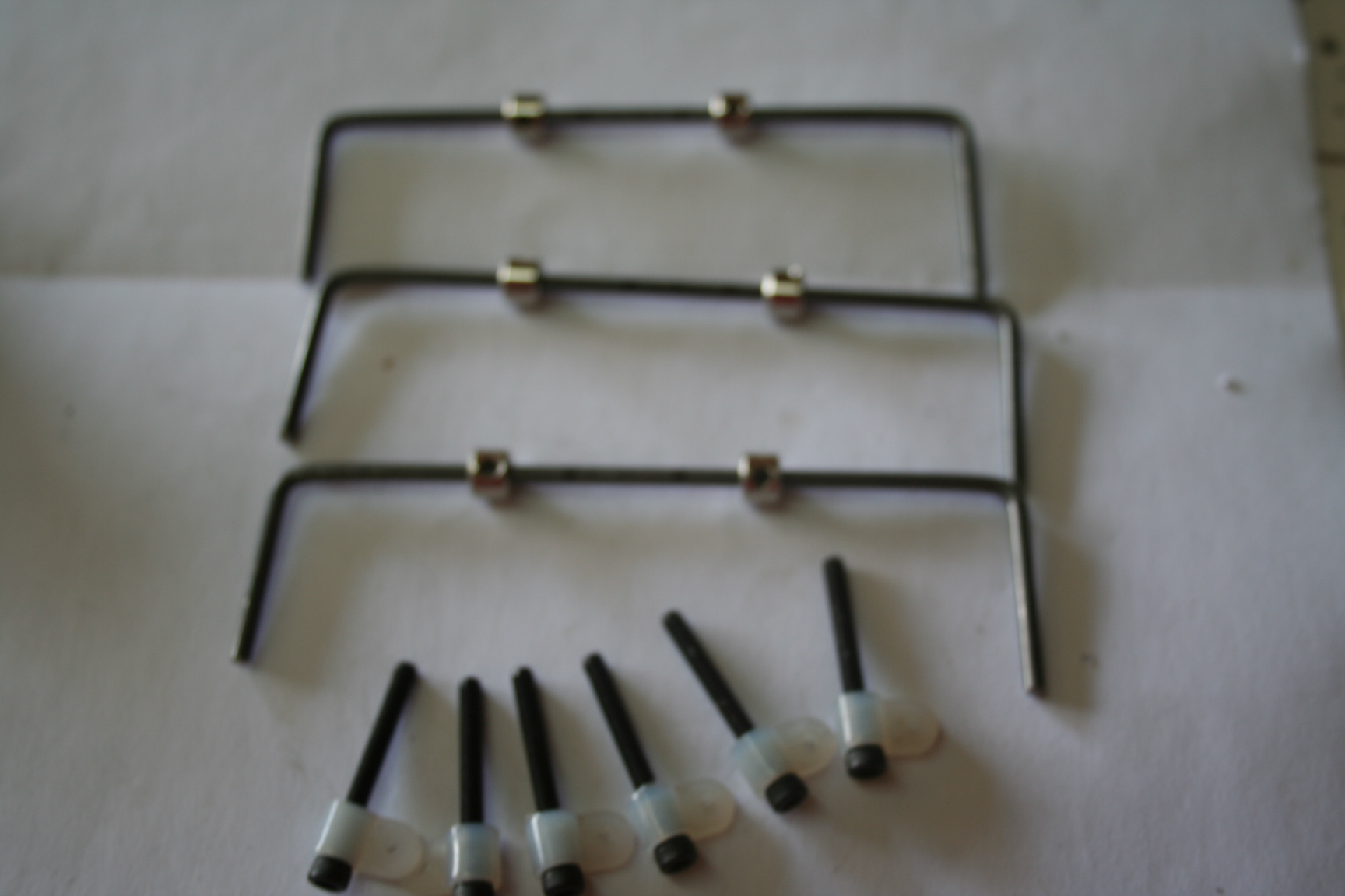
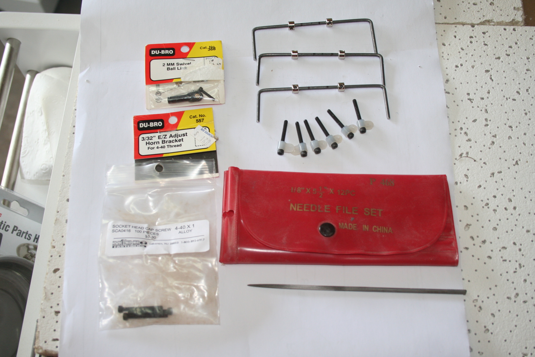
This picture shows the specific hardware used. Also pictured is the Jeweler's File kit used in the next step.
This picture shows the specific hardware used. Also pictured is the Jeweler's File kit used in the next step.
Last edited by Iron Dog; 05-21-2016 at 08:03 PM.
05-21-2016, 08:29 PM
#240
Thread Starter
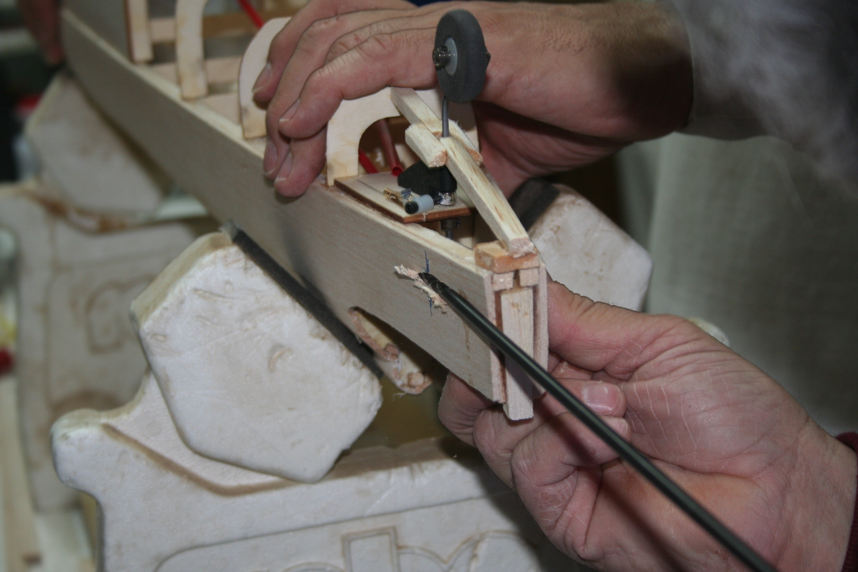
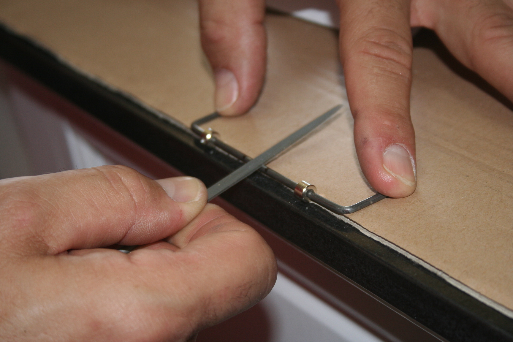
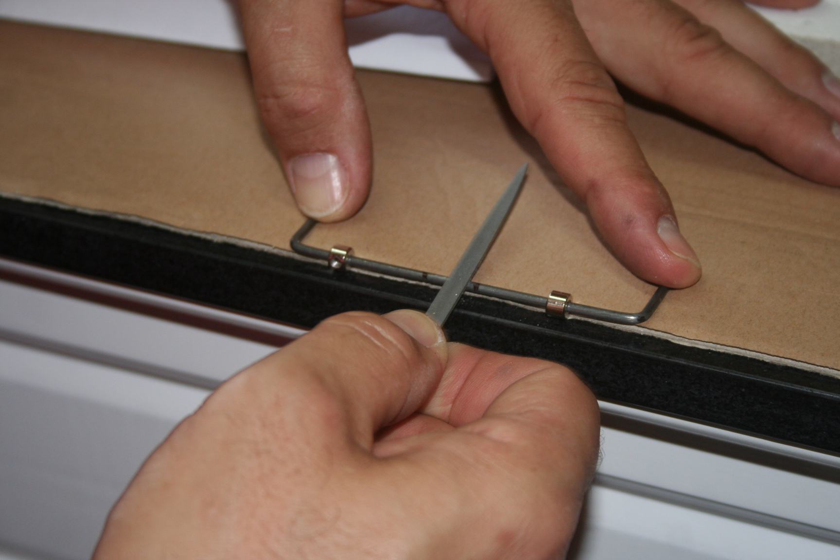
Slide the wheel collars towards the outside of the wire and using a Jeweler's File, file a flat spot in the middle -- wide enough for both wheel collars. It is difficult to see clearly in the pictures, but if you look closely, you'll notice that the file is angled to file the flat spot slightly forward (about 20 - 25 degrees).

The set screws were replaced with the 1" 4-40 socket head bolts and EZ Adjust Control horns that were pictured in the previous post, and tightened after installing the 2 MM swivel ball link in-between.
The set screws were replaced with the 1" 4-40 socket head bolts and EZ Adjust Control horns that were pictured in the previous post, and tightened after installing the 2 MM swivel ball link in-between.
Last edited by Iron Dog; 05-21-2016 at 08:40 PM.
05-21-2016, 08:56 PM
#241
Thread Starter
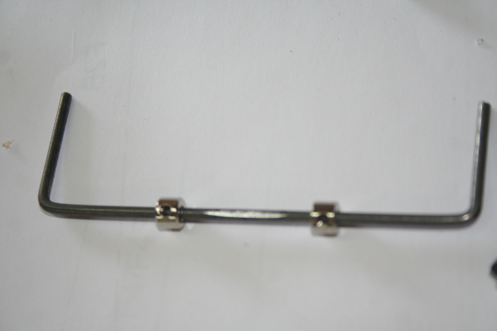
These are the three internal elevator control linkages AFTER they have been silver soldered.
To silver-solder them, I heated the wire and wheel collars using a propane torch, and pretreated with flux. To make sure that the nylon EZ Adjust Control Horns and Swivel Link did not melt, I wrapped the socket head bolts and remaining assembly tightly in a wet cloth, before heating.
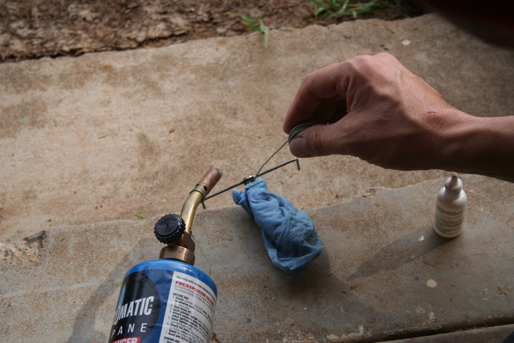
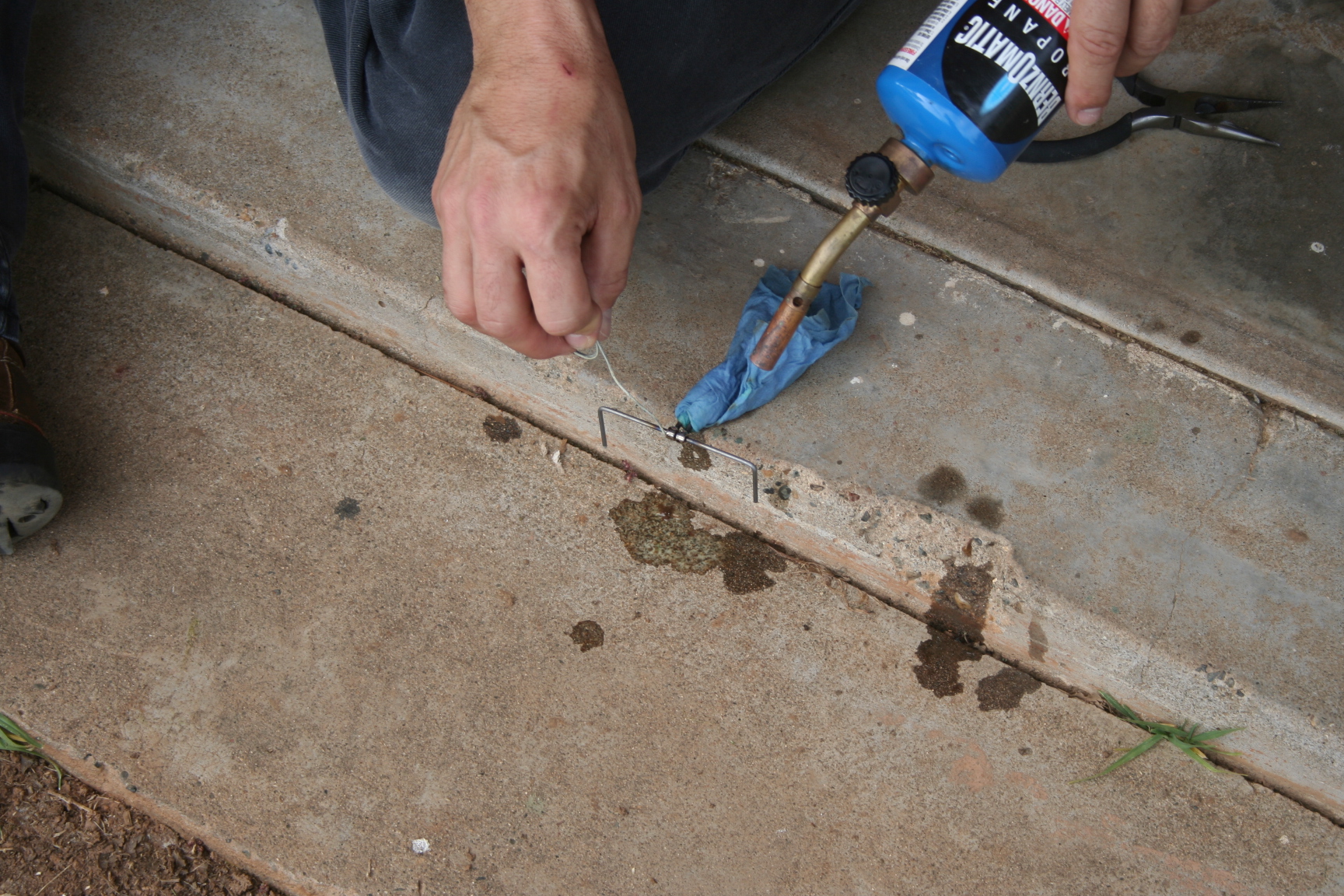
For anyone that has not soldered in this manner before, please note that the wire is heated on one side, and the solder is applied to the opposite side. (Do not heat the solder directly with the flame of the torch; instead, allow it to "wick" through a heated surface.)
To silver-solder them, I heated the wire and wheel collars using a propane torch, and pretreated with flux. To make sure that the nylon EZ Adjust Control Horns and Swivel Link did not melt, I wrapped the socket head bolts and remaining assembly tightly in a wet cloth, before heating.
For anyone that has not soldered in this manner before, please note that the wire is heated on one side, and the solder is applied to the opposite side. (Do not heat the solder directly with the flame of the torch; instead, allow it to "wick" through a heated surface.)
05-21-2016, 09:13 PM
#242
Thread Starter
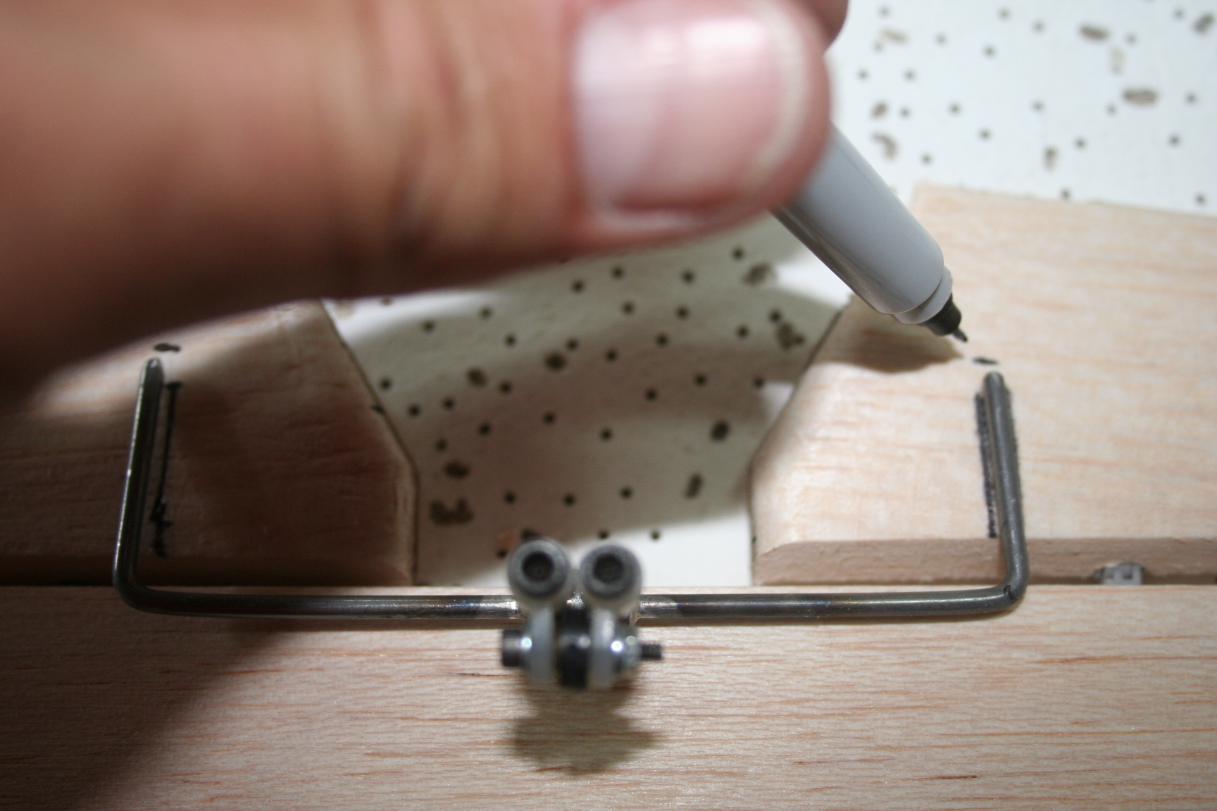
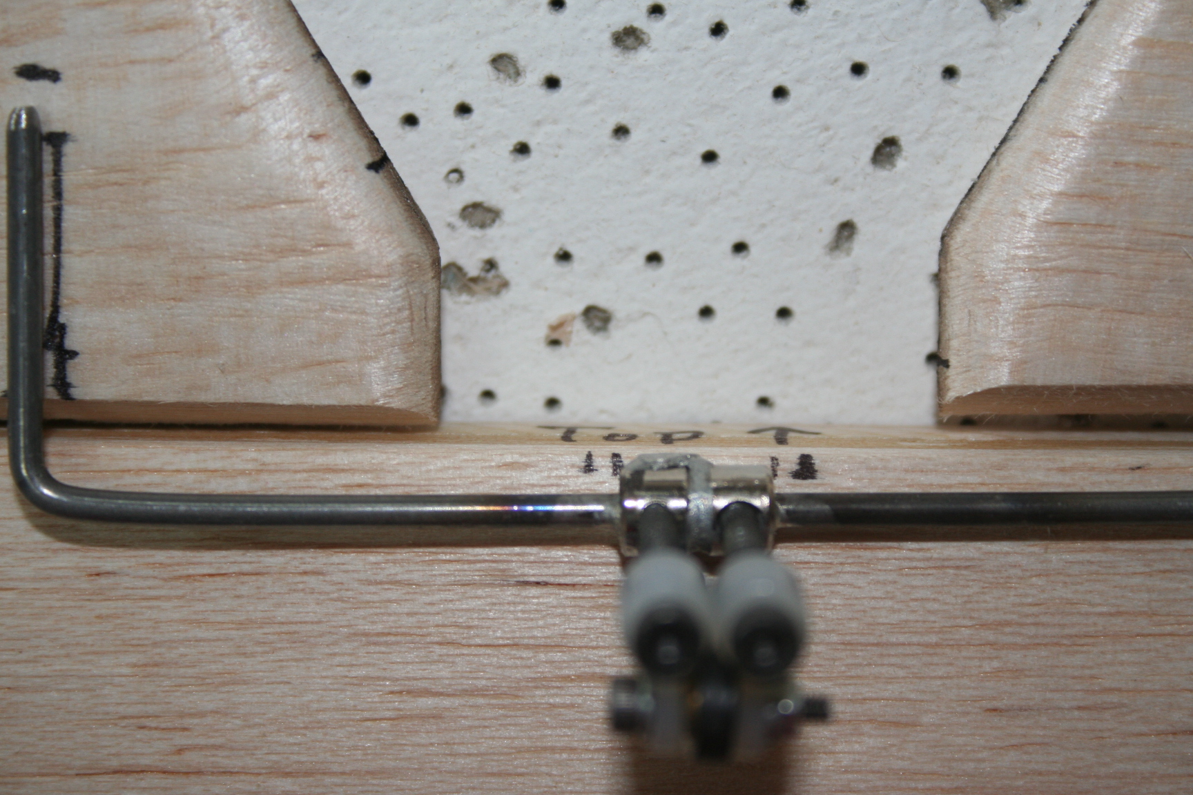
To properly align and drill holes for the elevator joiner wire into the elevator halves, center the control linkage assemly on the stab and elevators. Trace the outline of the joiner wire onto the bottom surface of the elevator halves.
The slight forward sweep of the bolts is noticeable in these shots when you consider the position of the camera is forward of the stab, pointed to the rear. This sweep angle is necessary for servo travel
clearance against the fuselage's rear post, when up elevator is applied.
The slight forward sweep of the bolts is noticeable in these shots when you consider the position of the camera is forward of the stab, pointed to the rear. This sweep angle is necessary for servo travel
clearance against the fuselage's rear post, when up elevator is applied.
Last edited by Iron Dog; 05-21-2016 at 10:14 PM.
05-21-2016, 09:21 PM
#243
Thread Starter
The rear center of the stab will also have to be notched for clearance of the wheel collars. So the position of the wheel collars is also marked.
A Dremel and bit are now employed to notch the elevator in the position marked, abotve.
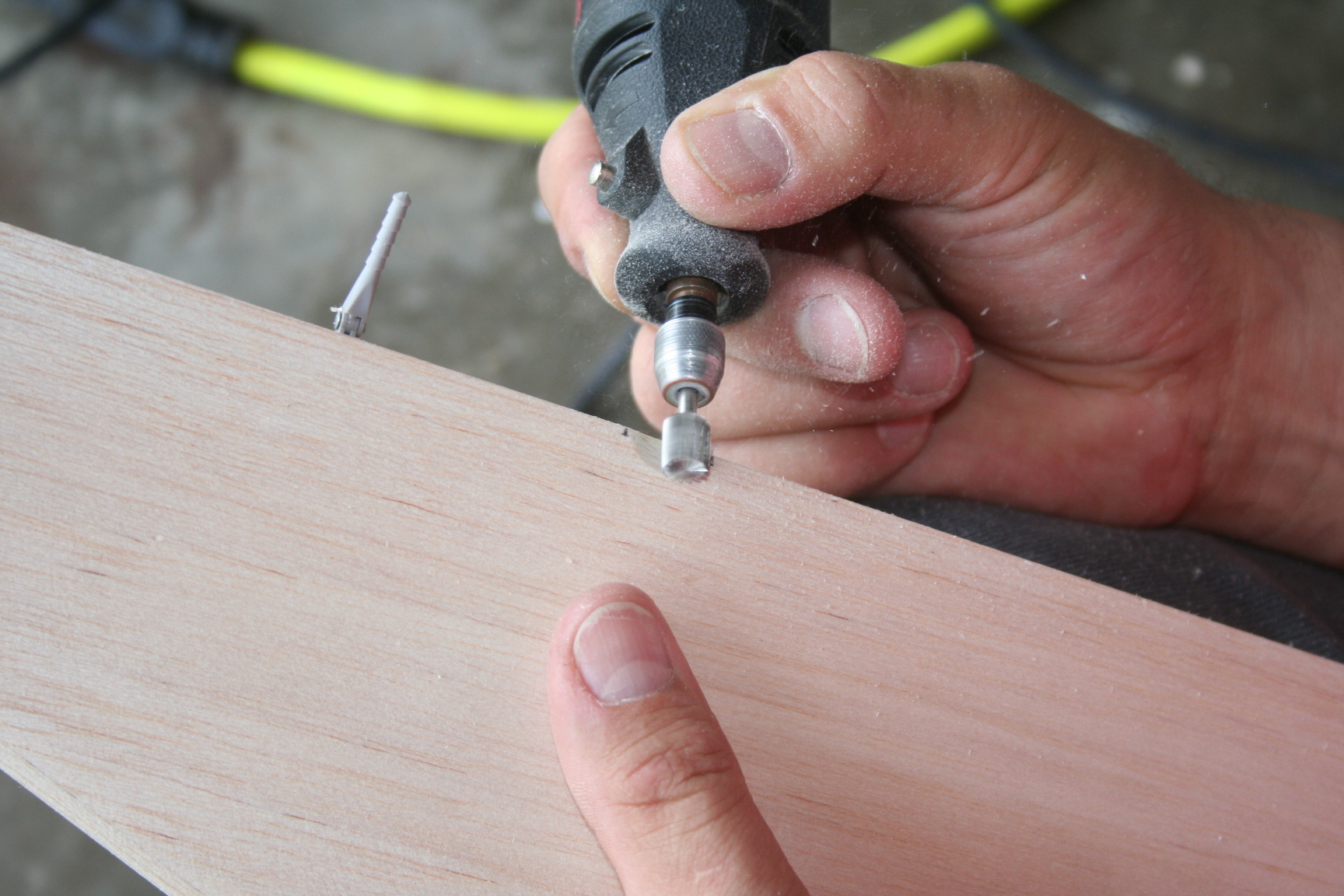
A Dremel and bit are now employed to notch the elevator in the position marked, abotve.
Last edited by Iron Dog; 05-21-2016 at 10:17 PM.
05-21-2016, 09:43 PM
#244
Thread Starter
I used an ice pick (scratch awl) to mark and start the hole, in the position needed for drilling the elevator halves for the joiner wire. Carefully drill the 3/32" hole, constantly checking and assuring alignment, both vertically and horizontally, into the control surface. Be careful not drill beyond the needed depth.
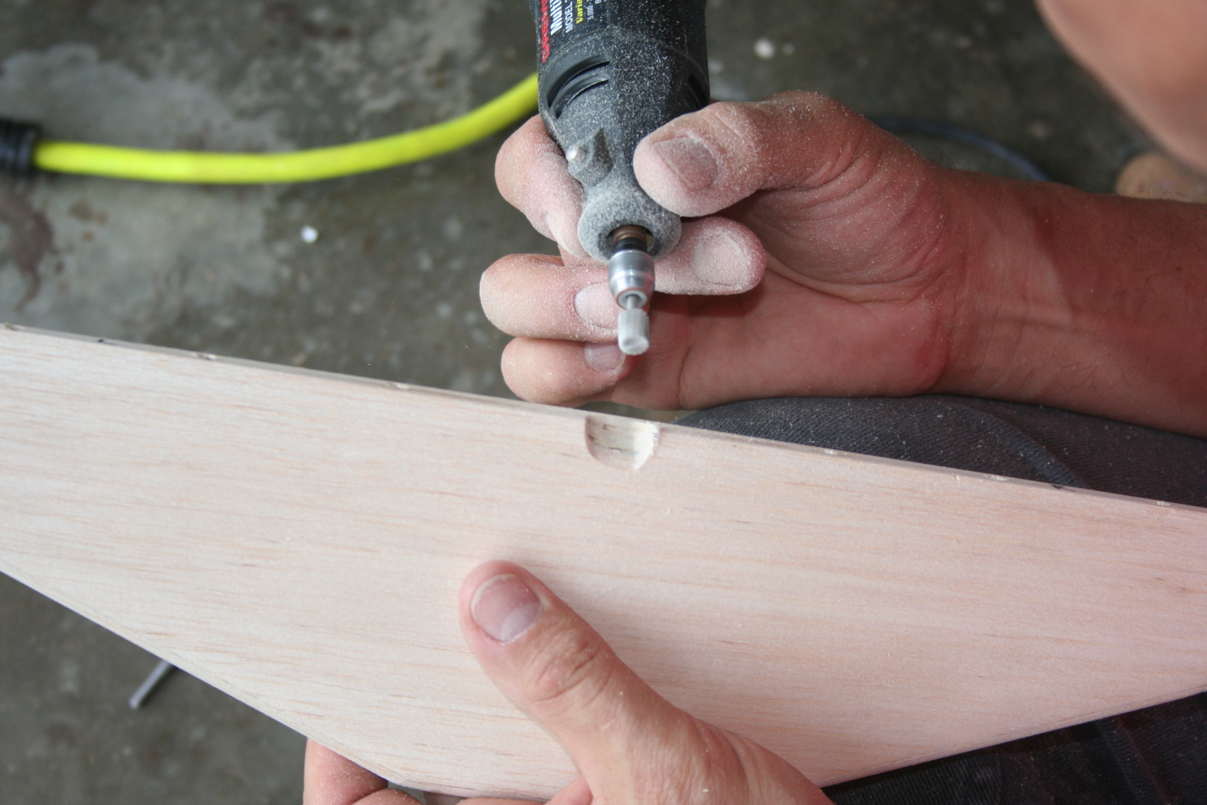
A small amount of 30-minute epoxy is mixed, and the joiner wire is epoxied into both elevatore halves.
(I think Tim approves of my elevator assembly!)
A small amount of 30-minute epoxy is mixed, and the joiner wire is epoxied into both elevatore halves.
(I think Tim approves of my elevator assembly!)
Last edited by Iron Dog; 05-21-2016 at 10:38 PM.
05-21-2016, 10:05 PM
#245
Thread Starter
So, the last post caught me up to the progress we'd made up to April 2nd.
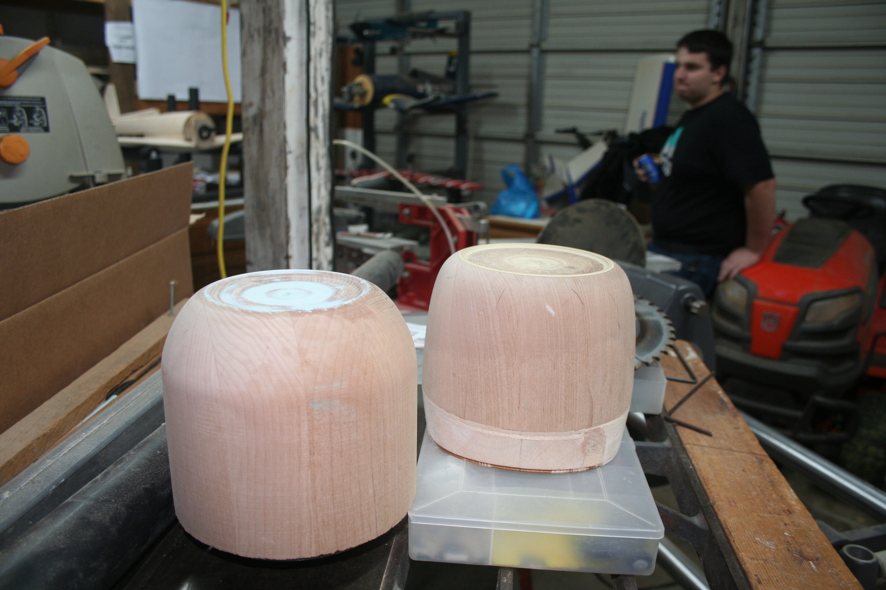
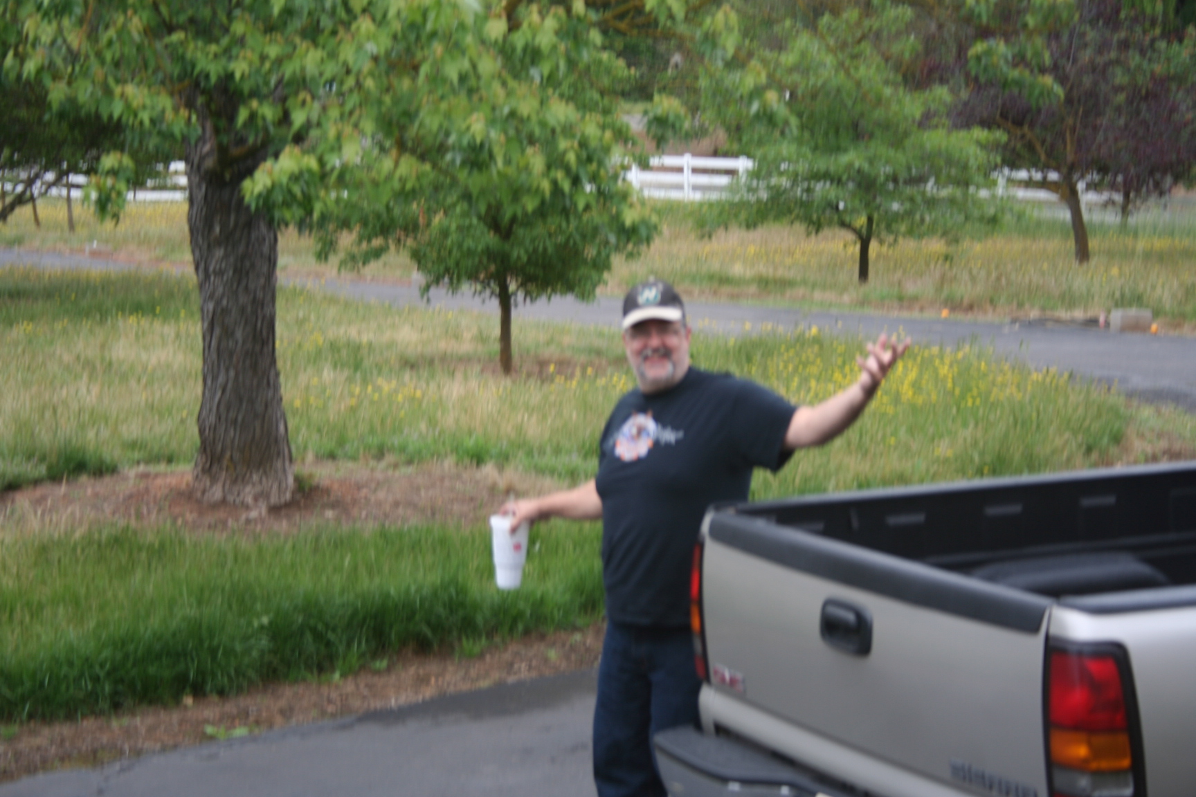
We were unable to get together again for 5 weeks. On build day, May 8th, this "stranger" shows up in my driveway and gets out of Tim's truck. (Can you believe it Jake, Kenny Rogers is gone!) While I miss my buddy Tim, at least this guy shows up with presents.
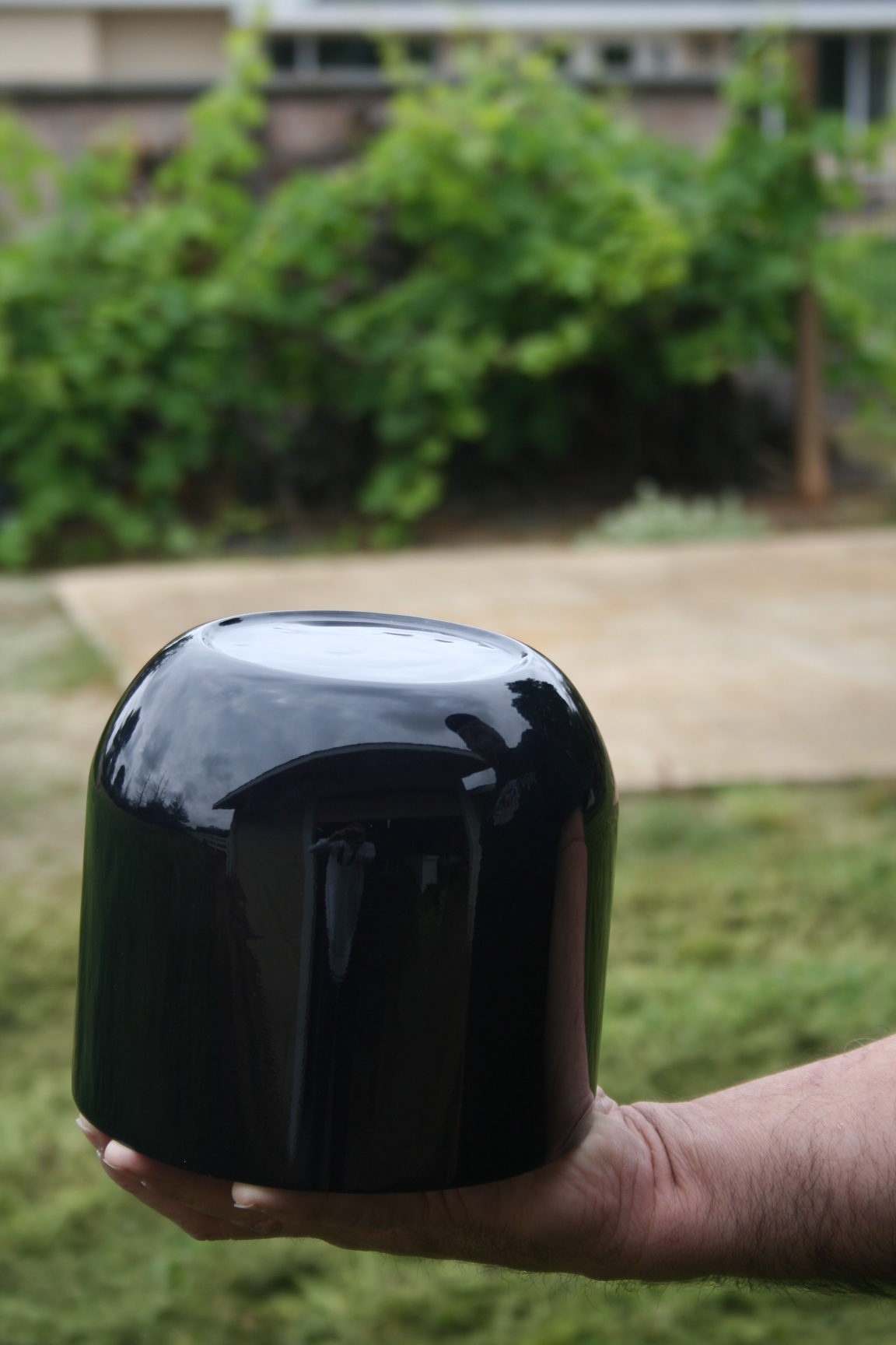
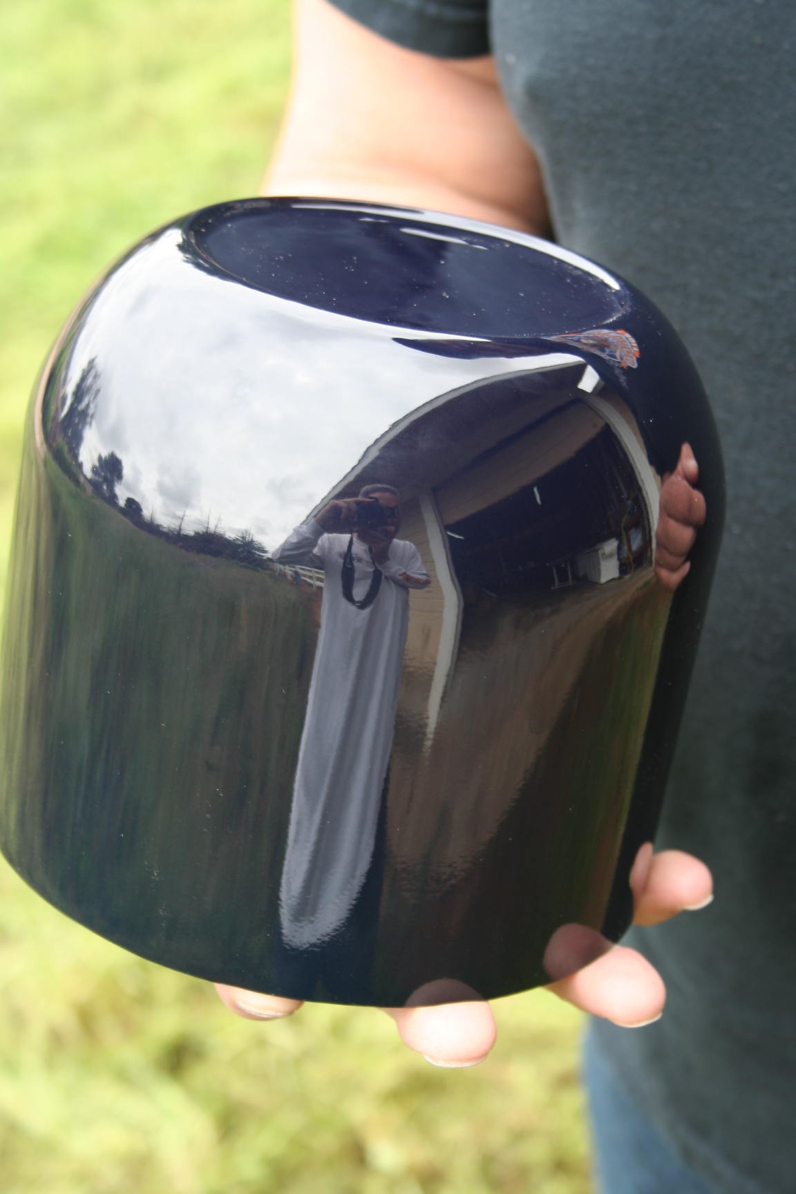
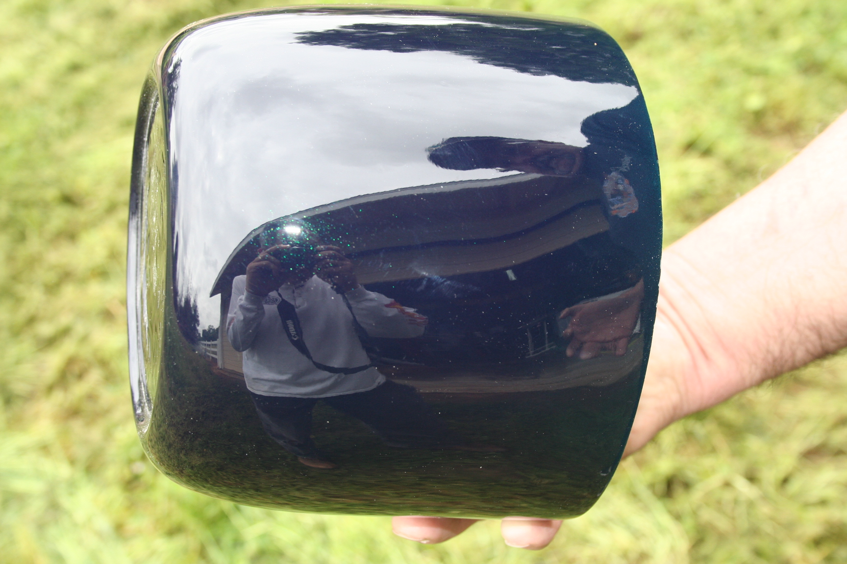
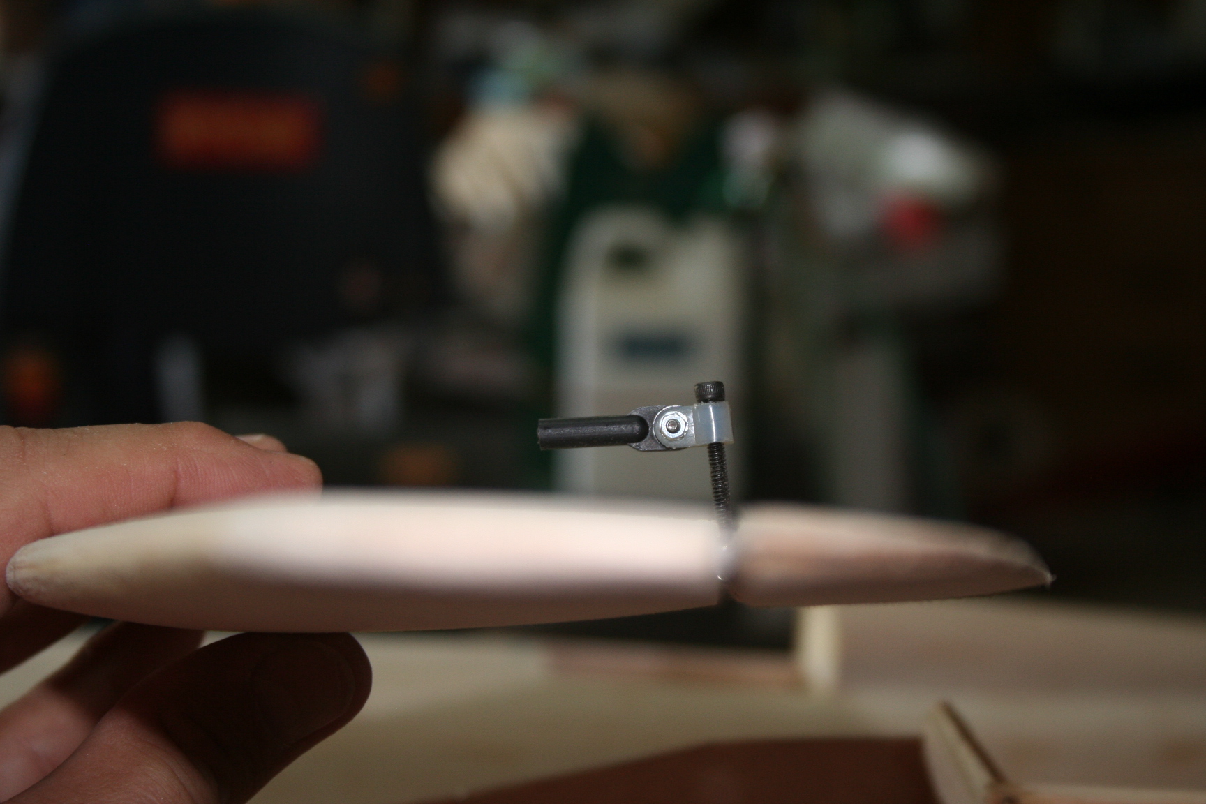
Here is the finished plug for the Czechmate cowl. Gorgeous, isn't it?!
I'm excited to make the mold for this one!
We were unable to get together again for 5 weeks. On build day, May 8th, this "stranger" shows up in my driveway and gets out of Tim's truck. (Can you believe it Jake, Kenny Rogers is gone!) While I miss my buddy Tim, at least this guy shows up with presents.
Here is the finished plug for the Czechmate cowl. Gorgeous, isn't it?!
I'm excited to make the mold for this one!
Last edited by Iron Dog; 05-21-2016 at 10:46 PM.

 06-17-2016, 09:31 PM
#247
Thread Starter
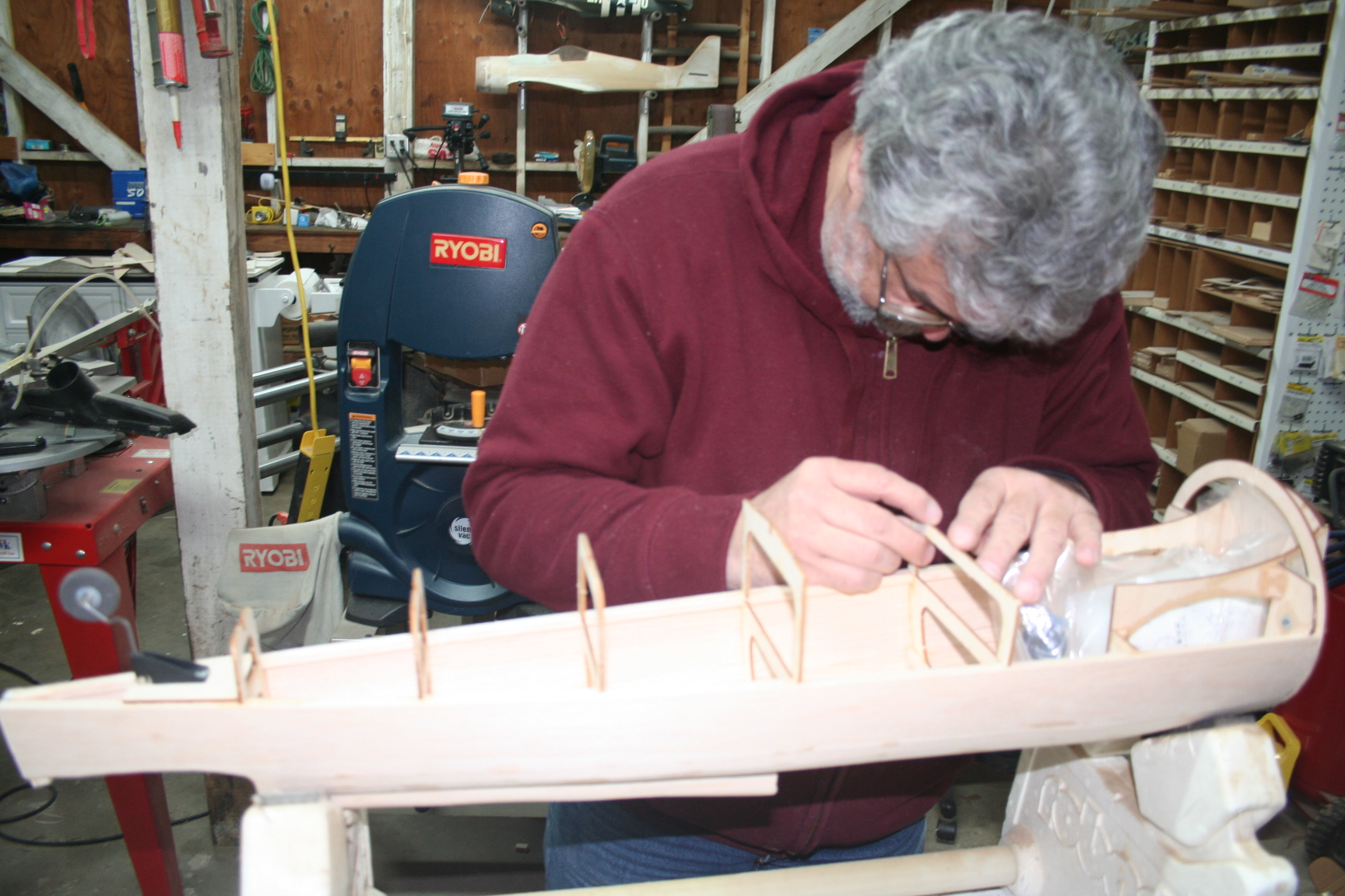
We started that morning, by filling the seams in the fuse between the planking.
Tim prefers the balsa fillers available from the hobby stores – especially the tinted-color variety; but lately, I tend to use Red Devil’s Onetime Lightweight Spackling as a balsa filling material. It is readily available at local hardware stores, and is far less expensive. Below, Tim is forced to use my spackling to fill in the seams of the planked fuse.
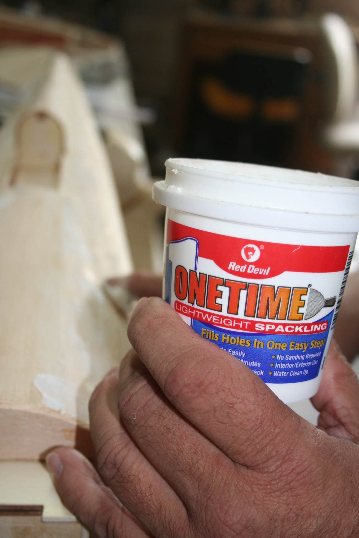
Tim prefers the balsa fillers available from the hobby stores – especially the tinted-color variety; but lately, I tend to use Red Devil’s Onetime Lightweight Spackling as a balsa filling material. It is readily available at local hardware stores, and is far less expensive. Below, Tim is forced to use my spackling to fill in the seams of the planked fuse.
06-17-2016, 09:36 PM
#248
Thread Starter
Ever since sanding it to shape, much earlier in the build, Eric was worried about the rigidity of the balsa block glued to the top of the vertical fin. He wanted to do something to reinforce it, in case the plane flipped over after landing. (A common experience when our race planes come in “hot” and run off into the grass section on a relatively short runway.) I suggested that we could use bamboo skewers to create a dowel-joint. After talking about it for so long, it only took me a couple months to remember to buy skewers at the grocery store, but I finally did just that. Wouldn’t you know it, Tim did the same, and showed up with bamboo skewers on this build day, as well.
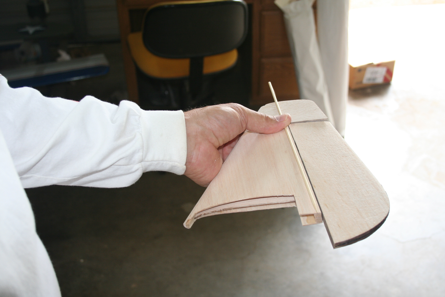
I hold the skewers against my fin assembly to check how to best align them.
I hold the skewers against my fin assembly to check how to best align them.
06-17-2016, 09:38 PM
#249
Thread Starter
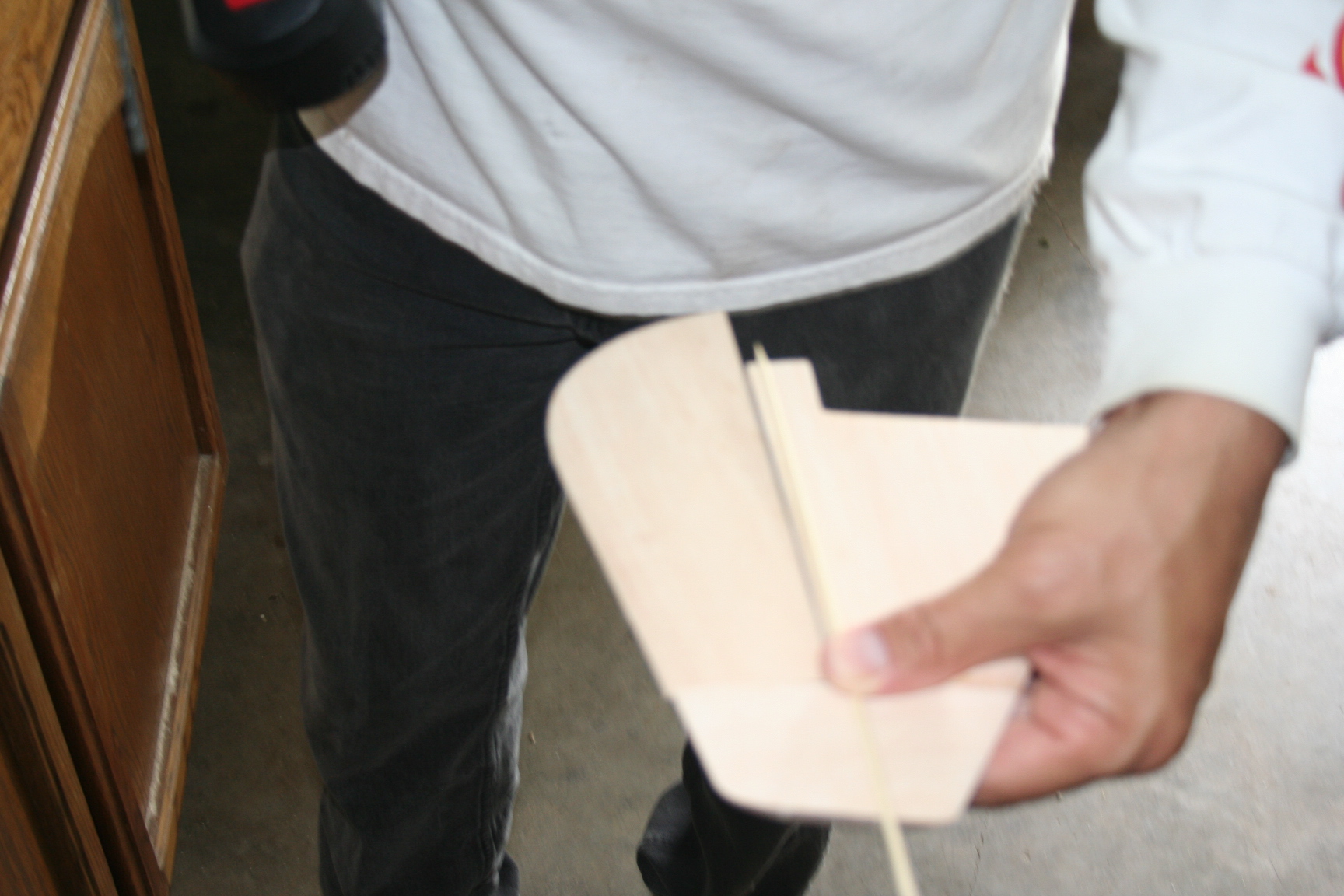
Once I decided how best to angle/align the dowels/skewers with the front and rear square stock that form the LE and TE of the vertical fin, I used an awl to mark and start a pilot hole, then drilled the hole to accommodate the dowel.
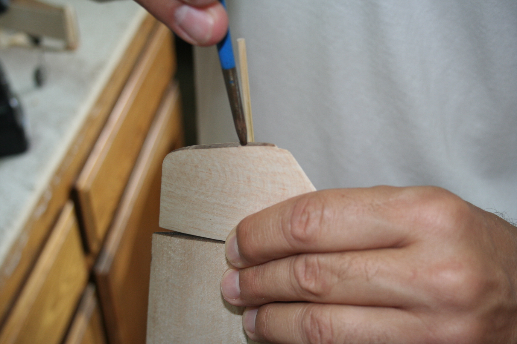
Apply thick CA into the hole and insert the skewer. Be careful not to go so deep on the rear skewer that it causes interference with proper placement of the top rudder hinge.
Apply thick CA into the hole and insert the skewer. Be careful not to go so deep on the rear skewer that it causes interference with proper placement of the top rudder hinge.
06-17-2016, 09:45 PM
#250
Thread Starter
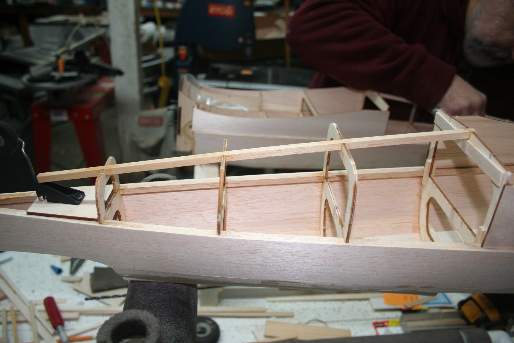
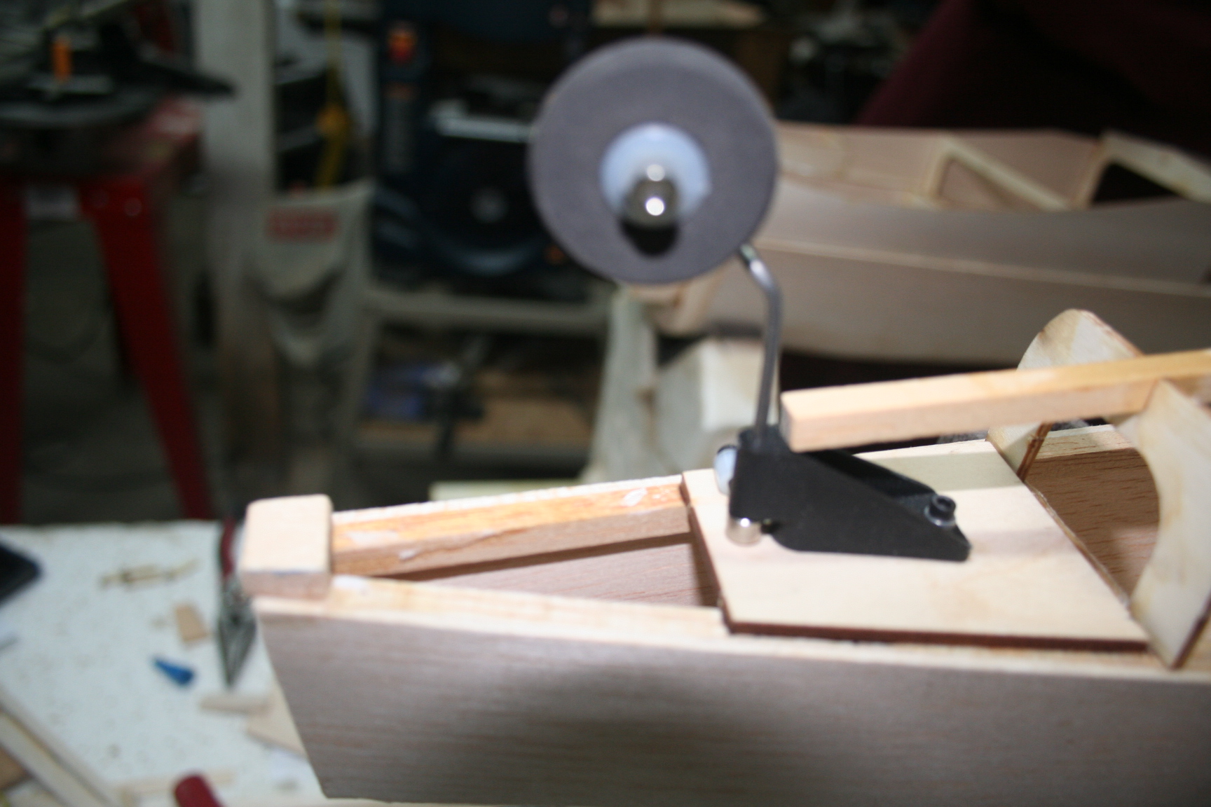
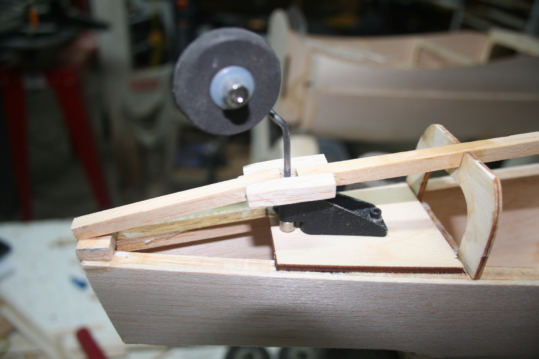
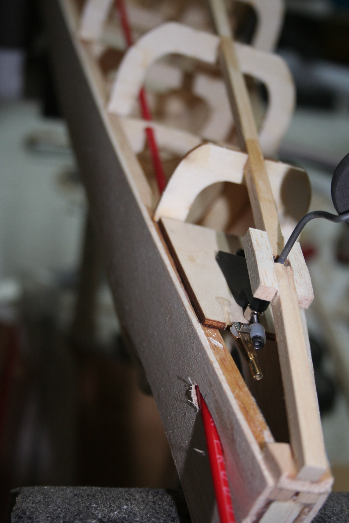
Trial fit the fuel tank. Leave plenty of room for the necessary plumbing. (If using a YS engine, you may wish to consider fuel filter and air check-valve placement, if placing inside the fuse; as well as the width of foam padding. I forgot to consider these additional factors and later realized I placed my servo mounting rails too far forward to mount everything without risk of kinking the fuel lines for the Tetra tank I was originally planning to use. Luckily I had an old Hayes tank that is shorter in length that I will be able to substitute, instead.)
After determining proper placement of the tank and fuel system, cut plywood servo mounting-rails to the width of the fuse, where placement is optimal for the equipment being used, somewhere behind the fuel tank. Trial fit, with servos in-place, to ensure servo output arms have plenty of clearance above the wing saddle. When satisfied with equipments’ placement, maintaining appropriate clearances, glue the servo mounting rails in-place.
Center the Elevator servo’s output arm as close to the centerline of the fuse, as possible. Position the Rudder and Throttle servos on the outsides of the rails, as necessary. (Consider the Throttle servo’s output arm in relation to the position of the carburetor of the engine being used.) Reversing/alternating servo orientation helps to minimize risk to interference of the output arms.
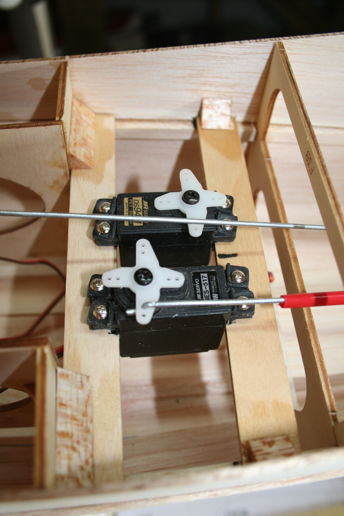
When servo placement has been determined, glue in tri-stock to reinforce the glue joints of the mount rails to the rest of the fuse structure. (Ensure tri-stock does not interfere with desired servo positions.)
After determining proper placement of the tank and fuel system, cut plywood servo mounting-rails to the width of the fuse, where placement is optimal for the equipment being used, somewhere behind the fuel tank. Trial fit, with servos in-place, to ensure servo output arms have plenty of clearance above the wing saddle. When satisfied with equipments’ placement, maintaining appropriate clearances, glue the servo mounting rails in-place.
Center the Elevator servo’s output arm as close to the centerline of the fuse, as possible. Position the Rudder and Throttle servos on the outsides of the rails, as necessary. (Consider the Throttle servo’s output arm in relation to the position of the carburetor of the engine being used.) Reversing/alternating servo orientation helps to minimize risk to interference of the output arms.
When servo placement has been determined, glue in tri-stock to reinforce the glue joints of the mount rails to the rest of the fuse structure. (Ensure tri-stock does not interfere with desired servo positions.)
Last edited by Iron Dog; 06-17-2016 at 11:13 PM.