


8th Scale Aviation's, "CzechMate" Short-kit, Group build
 06-17-2016, 09:51 PM
#251

Thread Starter

Just after we broke for lunch, Eric decided he wanted to try to fly his mini Foamie Warbird around my pastures. I warned him that I had flown my FlyZone Corsair and found it difficult to avoid my many trees. (That’s a nice way of saying, “I crashed into a really tall pine tree, and broke my plane when it fell and impacted the ground, shortly after I moved into this property a couple years ago.”)
Un-phased, Eric decided, “I’m sure I can avoid them!”
Anyone care to guess how that worked out for him? . . .

“Ummm . . . Ollie . . . Now what do I do?!”
Un-phased, Eric decided, “I’m sure I can avoid them!”
Anyone care to guess how that worked out for him? . . .
“Ummm . . . Ollie . . . Now what do I do?!”
Last edited by Iron Dog; 06-17-2016 at 11:01 PM.
 06-17-2016, 10:01 PM
#252
Thread Starter
(He never made it to either of my open pastures.)
This is Eric going net-fishing for a mini-foamie P-47 Warhawk out of another one of my pine trees.


This is Eric going net-fishing for a mini-foamie P-47 Warhawk out of another one of my pine trees.
Last edited by Iron Dog; 06-17-2016 at 11:05 PM.
06-17-2016, 10:16 PM
#253
Thread Starter
After lunch -- and Eric's short flight, we installed the pushrod tubes.
Tim includes the lasercut pushrod keepers, pictured below. Place a pair of these keepers on each of the tubes first. Run the tubes in a straight line, between the servo output arm and the elevator and rudder control horns. Glue the keepers to whichever part of the formers allow a good solid glue-bond, while equally spacing this reinforcement to keep the tube from flexing while under load and that will also keep the tubes straight.
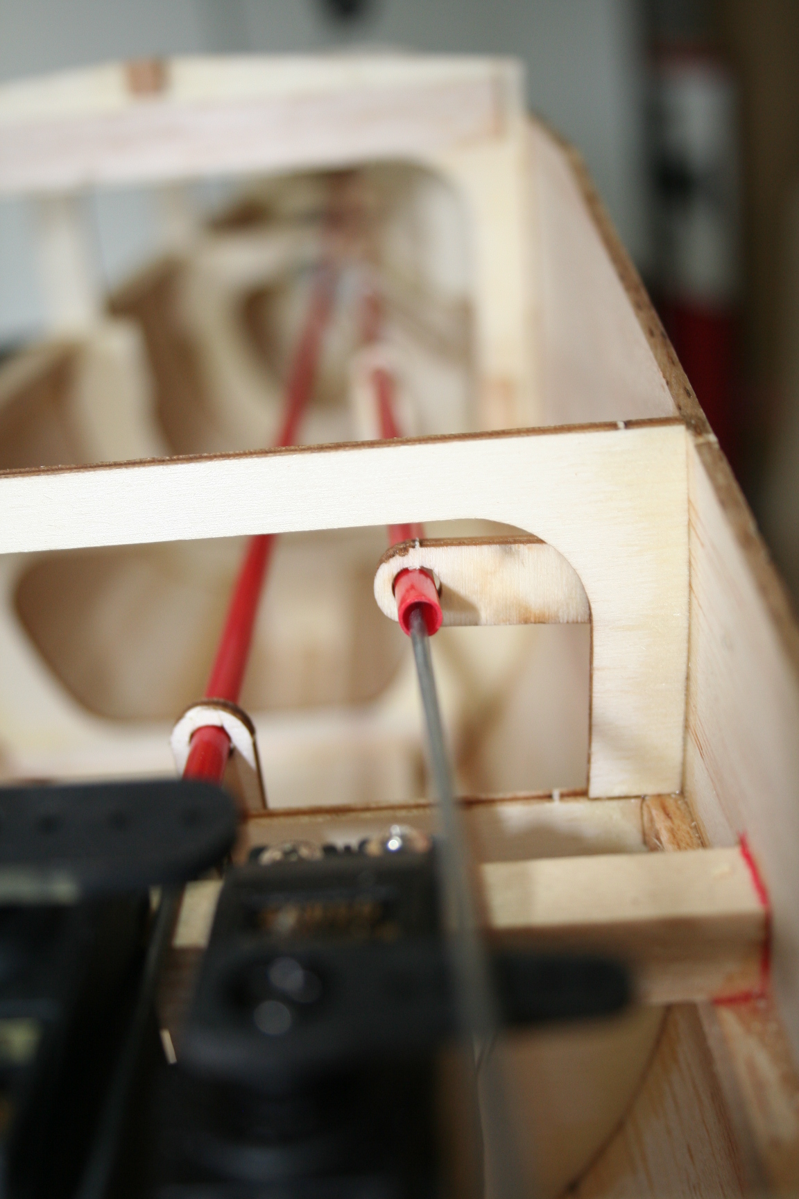

Tim includes the lasercut pushrod keepers, pictured below. Place a pair of these keepers on each of the tubes first. Run the tubes in a straight line, between the servo output arm and the elevator and rudder control horns. Glue the keepers to whichever part of the formers allow a good solid glue-bond, while equally spacing this reinforcement to keep the tube from flexing while under load and that will also keep the tubes straight.
Last edited by Iron Dog; 06-17-2016 at 11:07 PM.
06-20-2016, 05:12 AM
#254

Just after we broke for lunch, Eric decided he wanted to try to fly his mini Foamie Warbird around my pastures. I warned him that I had flown my FlyZone Corsair and found it difficult to avoid my many trees. (That’s a nice way of saying, “I crashed into a really tall pine tree, and broke my plane when it fell and impacted the ground, shortly after I moved into this property a couple years ago.”)
Un-phased, Eric decided, “I’m sure I can avoid them!”
Anyone care to guess how that worked out for him? . . .
“Ummm . . . Ollie . . . Now what do I do?!”
Un-phased, Eric decided, “I’m sure I can avoid them!”
Anyone care to guess how that worked out for him? . . .
“Ummm . . . Ollie . . . Now what do I do?!”
I like the way the pushrods went in!
Mike
 12-06-2016, 10:12 PM
#255
Thread Starter
Alright . . . Race season is over. So, time to get back to posting the progress of our build, thus far, in order to get you all caught-up. We haven't been able to get together very regularly these last few months to continue the build., but were able to do so a couple times in the last month. Now, let's see how well I can remember where we were -- and exactly what we did -- beginning 7 months ago:
After the pushrods were installed, the wing mounting block came next.
First, Tim set the wing into position on the wing saddle. He marked the position of the trailing edge of the wing onto the saddle doubler. Another mark was drawn one inch in front of the initial mark. The width of the fuse was measured between these marks, and a 1" wide piece of plywood was cut (ever-so-slightly oversized), and then carefully sanded to-size, to fit snugly between. If you look carefully at the pictures, you will notice a 1/2" balsa block was cut and sanded to the same width and glued to the center of the plywood wing mounting block.
Tim glued this 2-piece assembly ito position, about 1/16" below the edges of the saddle doubler.
Tri-stock pieces were then glued, as shown, to more carefully secure and reinforce the wing mount block.
Last edited by Iron Dog; 12-07-2016 at 06:12 AM.
12-06-2016, 10:22 PM
#256
Thread Starter
We then used some of our left-over bamboo skewers to further reinforce the integrity of the bond of the wing mounting block. One hole was drilled into the side of the wing saddle doubler and into the 1/4" ply block, and another hole drilled into the balsa block. (This was completed on both sides.) Epoxy was then applied, and the four skewer lengths were inseted.


12-06-2016, 10:29 PM
#257
Thread Starter
Eric follows suit:

(Quick note: I was busy taking pictures and wasn't watching carefully, to notice he was using thin CA, instead. He was unable to insert the skewer far enough, or at all, into the blocks before the glue set to have a solid dowel joint. We had to drill-out the skewer, then, try again. Do not use thin CA; if you want to risk thick CA, then you need to work very fast; using epoxy, for this purpose, is recommended.)
Wipe away excess; and when dry, cut the skewers nearly flush to the side of the wing saddle doubler. Sand the dowels/skewers flush.
Last edited by Iron Dog; 12-07-2016 at 06:27 AM.
12-06-2016, 10:45 PM
#258
Thread Starter
In preparation for fiberglassing the center section of the wing, wood filler was applied around the seam of the panels, and allowed to dry.
While drying, we installed the throttle pushrod to align with both the throttle servo and the position of the carb's control arm of a YS 70 engine. (None of us have actually decided if we are installing a YS 70 or the newer 80, yet.) Eric's wing and fuse are shown in the pictures, below.


While drying, we installed the throttle pushrod to align with both the throttle servo and the position of the carb's control arm of a YS 70 engine. (None of us have actually decided if we are installing a YS 70 or the newer 80, yet.) Eric's wing and fuse are shown in the pictures, below.
12-06-2016, 10:57 PM
#260
Thread Starter
The filler has dried, and the center section of the wing was sanded. A tack cloth removed the dust, and both the top and the bottom of the center section were fiberglassed, using heavy, 3" wide reinforcement tape and Z-Poxy finishing resin.


Last edited by Iron Dog; 12-07-2016 at 06:17 AM.
 12-08-2016, 05:34 PM
#264

 12-08-2016, 07:09 PM
#265
Thread Starter
My flight to Indianapolis was delayed, and by the time I finally arrived at AMA HQ, I only had enough sunlight left the day for one test flight. That flight was cut short when my P-39 developed a leak in the fuel system and dead-sticked. I landed safely, and replaced the entire fuel system just before dark. Went up early in the morning, to finally try to finally get some timed laps on the course, and even with all new equipment and lines, dead-sticked again. This time, was too low and on wrong end of runway for such ridiculously strong winds. Came up a couple feet short, and ripped the wing mounting blocks out of the fuse. I was forced to compete with my back-up, which I had just maidened. Needless to say, the competition didn't go so well, for me.
Both times, I found a pin-hole in a fuel line. Better to eliminate the risk of similar issues, when so easy to do so. With the P-39, I think it was the lines finding a fiberglass "needle." But have experienced pin-holes in the lines, where they come into contact with the firewall, a number of times over the last 20+ years, too. So, will take your suggestion, as well as wrap the rest of the length of the lines (as much as practical), to insulate them from friction for the rest of their run to the fuel tank.
In competition, reliability and consistency is critical. Good suggestion, Tommy.
Last edited by Iron Dog; 12-08-2016 at 08:00 PM.
12-10-2016, 11:34 AM
#266
We then used some of our left-over bamboo skewers to further reinforce the integrity of the bond of the wing mounting block. One hole was drilled into the side of the wing saddle doubler and into the 1/4" ply block, and another hole drilled into the balsa block. (This was completed on both sides.) Epoxy was then applied, and the four skewer lengths were inseted.
What do you mean left over? I think we have enough left over for 50 airplanes.

 12-11-2016, 09:55 PM
#269
Thread Starter
Time to make cowl molds!
In order to show Tim and Eric my methods for making molds, we are making them for both the CzechMate and Tim's new Rare Bear kit. That way, they can each do one. Simultaneosly, I am demonstrating by making a third -- a P-40 mold for my buddy Sergio. All three will be 2-part molds.
Pictures of the CzechMate and Rare Bear plugs, with the parting surfaces mounted; and, after all was waxed and PVA (thus the green tint) applied.
12-11-2016, 10:05 PM
#270
Thread Starter
The gaps between each plug and parting surface were filled with microballoons and resin. The following week, after curing-out, the whole assembly was sprayed with PVA again, then the tooling layer got "painted-on." Tim took Rare Bear, and Eric handles the duties on CzechMate:


12-11-2016, 10:32 PM
#273
Thread Starter
"Rinse . . . Lather . . . Repeat"
Repeating the process for the 2nd half of the mold. The parting surface was removed, and the flange of the first half serves as the parting surface, now. It was "keyed" with a Dremel and a spherical-shaped cutting bit, so that the 2nd half aligns and "locks" into place with the first.
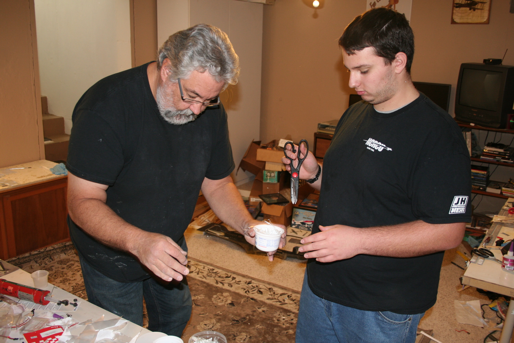
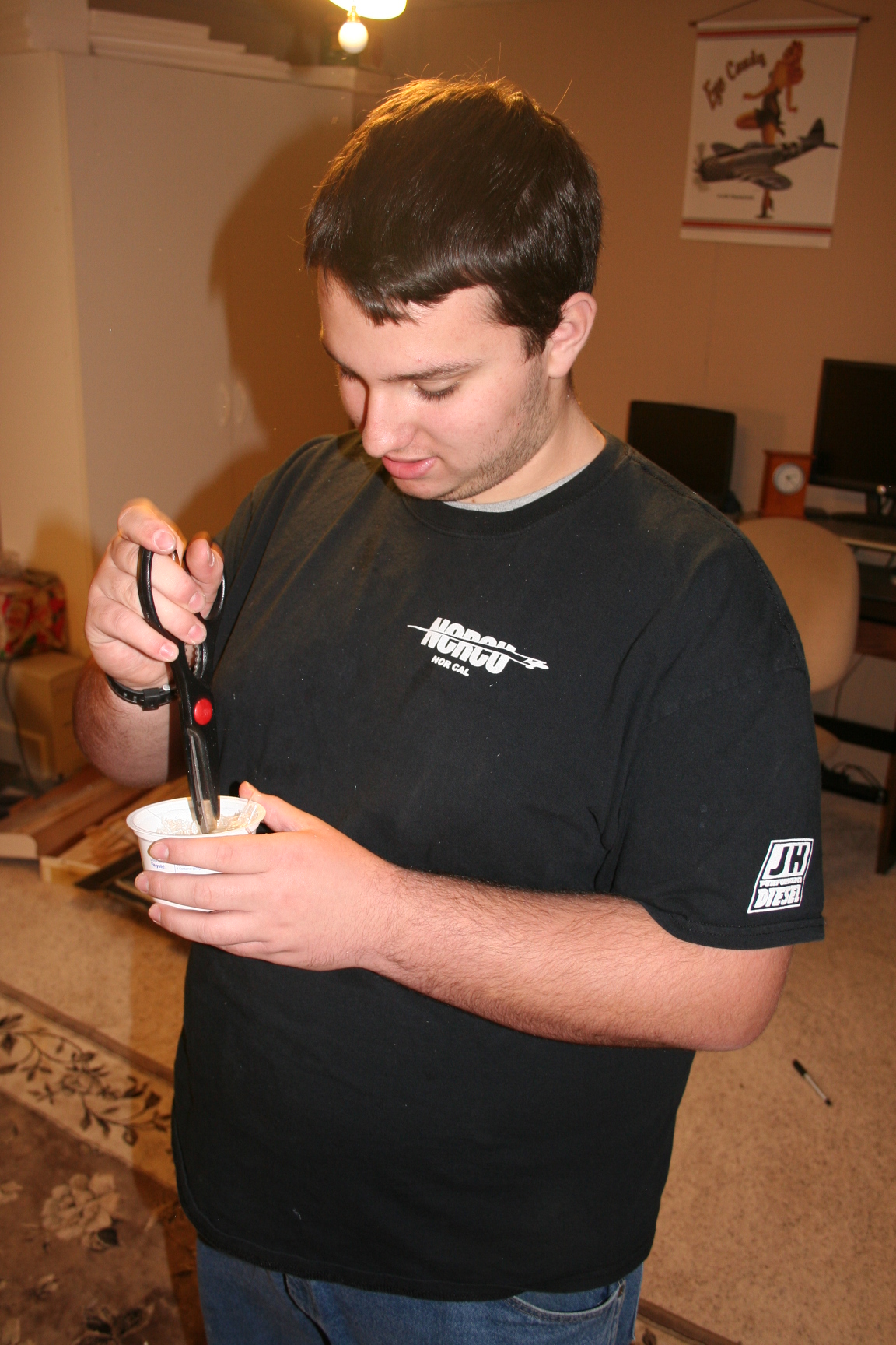
Here, I am having Eric and Tim each cut their own chopped fiberglass, so they can get the "full" experience (instead of me prepping everything in-advance). Afterwards, the other ingredients were mixed in, and the initial layer was applied -- just as before.
Repeating the process for the 2nd half of the mold. The parting surface was removed, and the flange of the first half serves as the parting surface, now. It was "keyed" with a Dremel and a spherical-shaped cutting bit, so that the 2nd half aligns and "locks" into place with the first.
Here, I am having Eric and Tim each cut their own chopped fiberglass, so they can get the "full" experience (instead of me prepping everything in-advance). Afterwards, the other ingredients were mixed in, and the initial layer was applied -- just as before.