


Freise aileron design help
 01-29-2012, 05:32 PM
#1

Hey guys,
I'm doing an A6M5 Zero and the full scale has bottom hinged freise ailerons. I have a cross section for the hinge and profile but my question is do I parallel the center line of the trailing edge for my hinge line or do I parallel the bottom of the trailing edge? In the exagerated tapered trailing edge below the green line parallels the bottom of the wing and the red line pallels the center.
I suppose I could take the easy way out and just do standard ailerons although that would give me the same "reveal" on top and bottom...One of the things that struck mee on the Zero was that the aileron looks half as wide on top as it is on the bottom due to the "Reveal' and I'd really like to recreate that. It also gives me an opportunity to stretch my building skills.
Any tips, hints or ideas regarding the design, build or implementation of these type ailerons would also be welcome.
Thanks!
 01-29-2012, 10:46 PM
#2

My Feedback: (60)
Join Date: Dec 2001
Location: Litchfield Park,
AZ
Posts: 7,677
Likes: 0
Received 25 Likes
on
23 Posts
Frets,
The axis of rotation on a Freise type aileron needs to be very low in order to function properly. Some times the hinges are even exposed (see the P-47 below) because the rotation point is underneath the control surface entirely. The Zero appears to be like the Spitfire in that the hinges lie very close to the bottom wing skin much like the green line in your graphic above. Very small changes in the rotation point can make a big difference and they generally take quite a bit of fiddling to get a nice tight gap all the way around at neutral and not bind when deflected. Well worth the effort though!
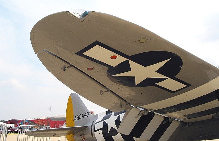
The axis of rotation on a Freise type aileron needs to be very low in order to function properly. Some times the hinges are even exposed (see the P-47 below) because the rotation point is underneath the control surface entirely. The Zero appears to be like the Spitfire in that the hinges lie very close to the bottom wing skin much like the green line in your graphic above. Very small changes in the rotation point can make a big difference and they generally take quite a bit of fiddling to get a nice tight gap all the way around at neutral and not bind when deflected. Well worth the effort though!
01-29-2012, 10:53 PM
#3

I have only built one model with freise ailerons, a Fokker 21 WW2 fighter.
I pivoted the ailerons aligned with the bottom surface of the wings, the reason
being the Fokker has no visible aileron linkages & I wanted to make the horn
as far from the hinge line as possible. This replicated the full size machine.
I used the large Robart hinge points. The rear half was glued into the aileron,
the front half fitted to alloy tubes which supported them back to the hinge line.
The front half was secured by small screws so the ailerons could be removed.
John.
01-30-2012, 12:31 AM
#4
Join Date: Aug 2005
Location: Mississauga,
ON, CANADA
Posts: 4,196
Likes: 0
Received 1 Like
on
1 Post
Hi, I have replicated Freise hinges on the ailerons on my S Connie model as it has hinges mounted at the hinge line on top side of the wing. There is no gap at this hinge joint as aileron pivots at the hinge line at the top on the level of the skin.. I had to make my own long hinge using large nylon dubro hinges by removing there pins n by inserting 14" long piano wire as new constant hinge pin!. This new hinge is bit stiff to operate as slim hi torque mg servos will be needed for it. Other then that its as scale as i can make for my model. See my.S Connie thread, its all there how i did it.
Sam
Sam

 02-01-2012, 04:27 PM
#6
Props4ever,
Nice build on the Connie there. I went through all 48 pages. Will be waiting on the maiden. I saw your ailerons and though they are good I need a top mounted horn and bottom mounted hinge for scale fidelity. Therein lies the problem..it's a complex freise assy not a simple one.
FlyerInOKC,
Unfortunately the TopFlite Cessna 182 is the top hinge also.
Boomerang1,
Good idea for the hinge extension.
Chad,
"they generally take quite a bit of fiddling to get a nice tight gap all the way around at neutral and not bind when deflected." doesn't even begin to cover the tediousness of the excercise!![X(]
I think I have a decent shape and pivot point worked out after highjacking Props4ever's penchant for making small profile dummies to work out angles shapes and such. Now just to transfer it to an 18''long tapered LE aileron. May do a jig for the taper, still pondering how to easily and faithfully sand the LE...easy and accurate may be mutually exclusive!
02-01-2012, 06:04 PM
#7
My Feedback: (60)
Join Date: Dec 2001
Location: Litchfield Park,
AZ
Posts: 7,677
Likes: 0
Received 25 Likes
on
23 Posts
Frets,
I can email you a wing plan for a Spitfire which shows how the Freise ailerons are accomplished on the Spit which appears very similar to the Zero.
[email protected]
I can email you a wing plan for a Spitfire which shows how the Freise ailerons are accomplished on the Spit which appears very similar to the Zero.
[email protected]
02-01-2012, 07:21 PM
#8
Thanks Chad.
I think I have a working model at this point. You were certianly right though, as far as the pivot point location. A little left, right, up or down make a big difference. If the Spitty is much different than this I would enjoy seeing it.
I'm [email protected]
I think the hardest part now is shaping the leading edge. Then transferingthe pivot point location to the real aileron. It's about an 18'' long aileron.
I'm also a little concerned that at the full up deflection there is 3/8" x 18" exposure sticking down which is the equivalent of a 5-6 sq/in slab of wood stuck up under the wing. That seems like a huge amount of drag. I know that the intent of the freise aileron, but it does seem a lot.
02-01-2012, 08:22 PM
#10
My Feedback: (60)
Join Date: Dec 2001
Location: Litchfield Park,
AZ
Posts: 7,677
Likes: 0
Received 25 Likes
on
23 Posts
ORIGINAL: frets24
I'm also a little concerned that at the full up deflection there is 3/8'' x 18'' exposure sticking down which is the equivalent of a 5-6 sq/in slab of wood stuck up under the wing. That seems like a huge amount of drag. I know that the intent of the freise aileron, but it does seem a lot.
I'm also a little concerned that at the full up deflection there is 3/8'' x 18'' exposure sticking down which is the equivalent of a 5-6 sq/in slab of wood stuck up under the wing. That seems like a huge amount of drag. I know that the intent of the freise aileron, but it does seem a lot.
02-02-2012, 04:19 AM
#11
All true indeed. In the course of standard manuevers I don't think I ever use more than just a touch of aileron to initiate a turn anyway, and it's not like I'm going to be doing "corkscrews" (6-8 revolution/3sec) with the Zero either.[&:]
Will look at the file you sent this evening. Thank you.
Will look at the file you sent this evening. Thank you.
