


Martin Baker MB.5 Giant Scale Build
 07-01-2018, 06:23 AM
#1

Thread Starter

Hi Everybody -
I am back to square one in trying to find somebody willing and able to create a set of giant scale plans for the Martin Baker MB.5 for me
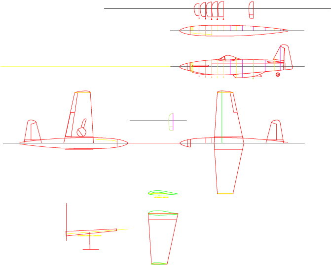
Am looking for a 1/5th scale bird putting the w/s in at ~91-inches to be powered by 75cc-85cc engine. Would like to have the CAD files as well as PDF.
Any help would be appreciated.
Tom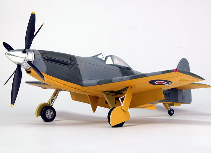
I am back to square one in trying to find somebody willing and able to create a set of giant scale plans for the Martin Baker MB.5 for me
Am looking for a 1/5th scale bird putting the w/s in at ~91-inches to be powered by 75cc-85cc engine. Would like to have the CAD files as well as PDF.
Any help would be appreciated.
Tom


 07-02-2018, 03:45 PM
#3
Thread Starter
Hi Dan -
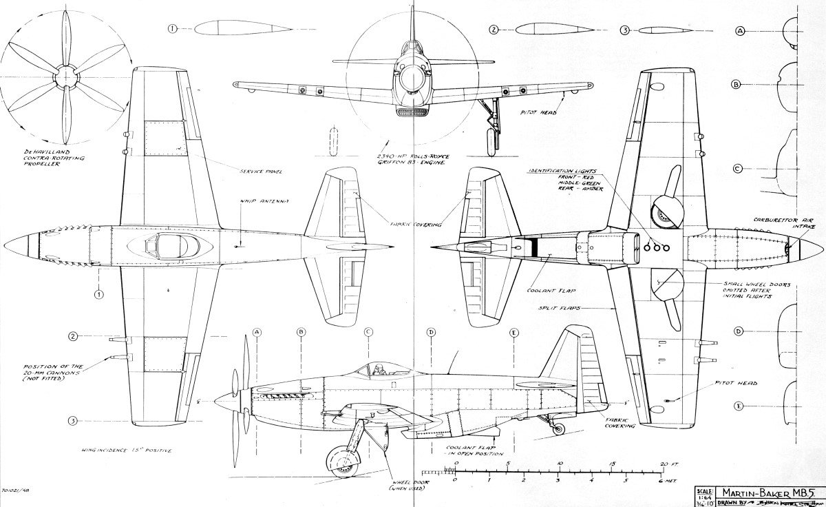
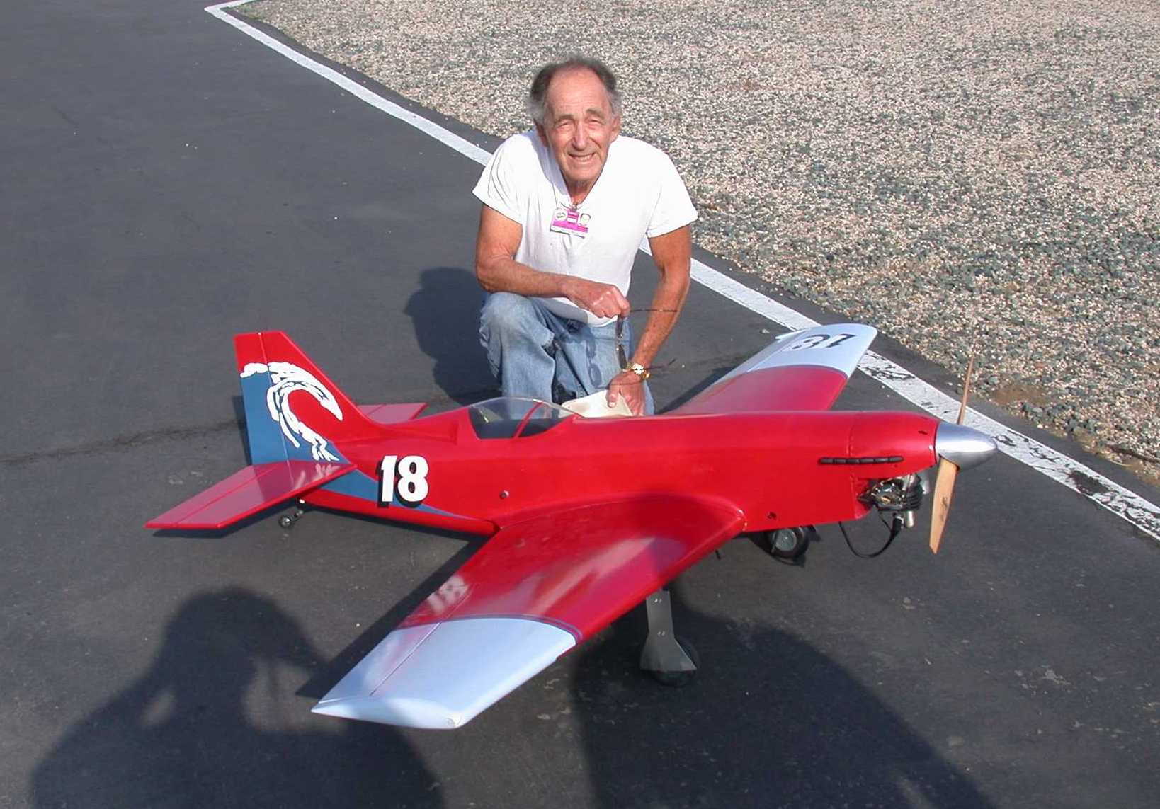
Thanks...you've crafted a nice plane! I like the Tsunami. Unfortunately, it's not the MB.5, which is what I am after. I have a guy that will make me a set of plans IF I can get a hold of the actual factory drawings. I've contacted Martin Baker, though, and they are unwilling to provide them to me so I'm hoping somebody else could do the job from a scale outline.
Tom
07-05-2018, 05:19 AM
#5
Thread Starter
Hi TDSTAF -
Thank you for your reply to my post. I am not looking for "perfect scale" if that is what you are asking; I am not looking to compete in contests with the craft or anything. I would like to have "true scale" outline and shape, though, if that makes sense.
Somewhere in my stuff I have an old set of Bob Holman MB.5 plans and a canopy for a 55" w/s model, but I'm nearly exclusively building giant scale these days and do not have the engineering drawing skill to make an enlargement. I know that lots of guys will basically scale up a set of plans and if I was only going from 55" w/s to say 70" that's one thing, but not 2x scale-up. The wing stresses and loading...etc. are entirely different if you know what I mean.
Thanks - Tom
07-05-2018, 10:30 AM
#6

There is nothing weird about this plane and the drawings you show..why not simply blow up the fuselage sections to the scale you want,and notch at intervals for the stringers of whatever size you use,like 1/4x 1/4.shouldn't take more than a day to do so.Take photos with your cell,and print to scale,so you have a document. That means make your document 261.79" x 198.9" in Paint.net.Then you can move it into a cad program and edit it.What I do is make copies of each fuse former,and paste them 3d perpendicular to the fuse at the station required on the side view
Last edited by alex5; 07-05-2018 at 11:39 AM.
07-06-2018, 05:20 PM
#8
Thread Starter
Hi Alex5 -
Thank you for your responses. I've tried blowing up JPG and BMP images before w/o success, but I've never tried taking pictures of the image w/ my phone. I assumed the result would be the same, no? I get what you are saying about the MB.5 being similar to a P51. I thought about that too, but for me the scale outline is quite a bit different between the two.
I think I will try your suggestion and see how that works. Also, I didn't know that I could pull drawings from PAINT into CAD.
07-06-2018, 07:32 PM
#9
as I said ,import the scale images you posted into Paint.net,then scale those to the dimensions I said.that gives you a 91 " ws view.I tested it,and found that the verticals are true,unlike so many others.from there,save first,then import into autocad,or any other ,as a jpeg image 1 to 1 or scale it by reference mode..Really ,rectangular crop in paint.net as multiple image saves,one for each fuse former,then paste into acad,one after the other,until you have a stacked image set in 3d.I would do it and show you,but then ,my day is spent,just showing you,and I have no $ to explain it.
07-06-2018, 07:42 PM
#10
The P51 model for a successful 91 inch ws, RC model(like ziroli 98") would be the same.Copy that method,or that of MRaerodesign, and you won't have any issues.Just click and paste from the scaled up image,not the original.You change the side view ,then insert the fuse
formers as per their new positions
formers as per their new positions
07-06-2018, 07:59 PM
#11
I can supply one day,8 hrs for $100,converting your image to scale ,in dwg format,tracing the fuse formers and maybe more,depending on how far I get.I am on short term med leave.You can use that in a short kit

 07-08-2018, 12:53 AM
#15
My Feedback: (60)
Join Date: Dec 2001
Location: Litchfield Park,
AZ
Posts: 7,677
Likes: 0
Received 25 Likes
on
23 Posts
I thought you were offering to establish the basic outline of the aircraft and trace the formers. Essentially the stuff that is necessary prior to starting the design work for a model. In that context, yes, that is pretty close to 3/4 finished. My apologies if I misunderstood what you were offering to do.
07-08-2018, 08:16 AM
#16
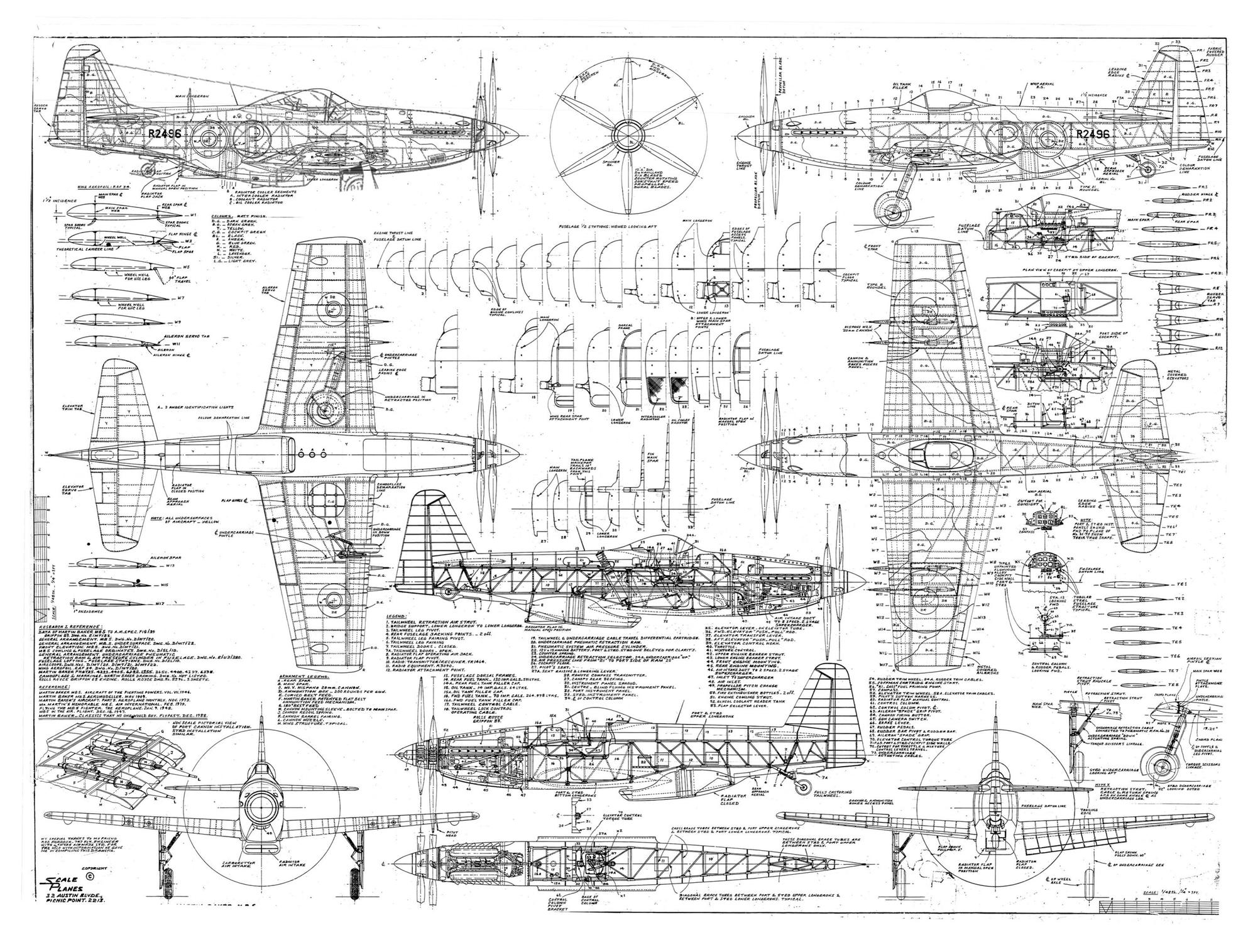
those outlines have been pretty much established in the excellent drawing provided..which ,when brought to the size that Sundance wanted,align very well indeed. For use in laser,the outlines aren't used ,generally,as any stick stock can provide that without laser or cnc being used. The most vital components are those which have formers or other shapes being notched for stringers,wood locks(pieces being tied together using notches) like in the nose and airscoop, things with holes that line up,for tubes channels,etc.
The one view used is the side view,which gives the profile..and is that becomes the main building jig.
Keep in mind that the fuse is 77 inches approx, and that means some 28 fuse formers with notches,if using old school stick build,with structure for the vert stab,also needing internal structure,and locations for servos,and tail gear. It is not just follow the outside and all comes together! The wing is relatively simple,but it is a waste of time to make in virtual solids, as the line files are what is needed,for laser or gcode for cnc, so each rib has to be designed and placed to assure fit..the same is true of the horizontal stab.
07-08-2018, 08:34 AM
#17
From a builder's view,you need 2 half wing mirror views,a fuselage fuse side view,a fuselage top view and the horizontal stab top view.That is done by cutting (editting )the full size image giving 5 smaller plan views,which you can print,or have printed by Kinkos,FEDex,Staples,Office depot..etc.First you check out what size is the printer,then size your documents accordingly,at full scale of your model.I use a projector to blow up the other details for reading and viewing.By the way,the cost of printing page views A11 equals the cost of full sheet views.I know as I printed an 8 foot Caribou using Letter size,and a 8 ft Twin Otter.You would be happy if you can have it printed on Printer mylar.
07-13-2018, 09:21 PM
#18
Like I Said a huge undertaking..
I spend any where form 40 to 60 hours drawing and placing notches on former's on a ..40-.60 size model then possibly another 10 to 12 hrs on setting up laser cut sheets..
This is just information on what is entailed for the time and effort your asking someone to help you with.
Its not just scan, copy, and cut. You basically have to draw and assemble every thing in CAD to see if it will work and then some of the parts may not fit after they are cut.
I don't want to discourage you I'm just trying to inform you of what is entailed..
Tim
07-14-2018, 05:24 AM
#19
Thread Starter
Like I Said a huge undertaking..
I spend any where form 40 to 60 hours drawing and placing notches on former's on a ..40-.60 size model then possibly another 10 to 12 hrs on setting up laser cut sheets..
This is just information on what is entailed for the time and effort your asking someone to help you with.
Its not just scan, copy, and cut. You basically have to draw and assemble every thing in CAD to see if it will work and then some of the parts may not fit after they are cut.
I don't want to discourage you I'm just trying to inform you of what is entailed..
Tim
I spend any where form 40 to 60 hours drawing and placing notches on former's on a ..40-.60 size model then possibly another 10 to 12 hrs on setting up laser cut sheets..
This is just information on what is entailed for the time and effort your asking someone to help you with.
Its not just scan, copy, and cut. You basically have to draw and assemble every thing in CAD to see if it will work and then some of the parts may not fit after they are cut.
I don't want to discourage you I'm just trying to inform you of what is entailed..
Tim
Oh trust me, I know that this will not be an easy undertaking...even for an experienced designer. The one thing you touched on though, which is not necessary for me, is that I wouldn't need the parts layout for laser cutting. I hand machine cut all of my work. As far as the detail for notches...etc. that isn't necessary either. I improvise a lot on my work (that's what makes scratch building really enjoyable. Truthfully, if I could figure out a way to scale up the one attached detailed image that I've posted here, I would be all set. Unfortunately, importing the JPG into Paint and scaling it leaves a lot to be desired because the resolution is shot. I have Solid Edge and I cannot import an image file into it for editing either. The one fellow in the thread mentions Paint.net....not sure what that is but I haven't been able to locate it on the net. That leaves printing the image and taking it down to Staples Print Services and trying to scale it up that way, I would have to scale up individual sections though (not a big deal) because the largest width paper size is 36"
Thanks for your input!
Tom
07-14-2018, 06:25 AM
#20
Hi Tim -
Oh trust me, I know that this will not be an easy undertaking...even for an experienced designer. The one thing you touched on though, which is not necessary for me, is that I wouldn't need the parts layout for laser cutting. I hand machine cut all of my work. As far as the detail for notches...etc. that isn't necessary either. I improvise a lot on my work (that's what makes scratch building really enjoyable. Truthfully, if I could figure out a way to scale up the one attached detailed image that I've posted here, I would be all set. Unfortunately, importing the JPG into Paint and scaling it leaves a lot to be desired because the resolution is shot. I have Solid Edge and I cannot import an image file into it for editing either. The one fellow in the thread mentions Paint.net....not sure what that is but I haven't been able to locate it on the net. That leaves printing the image and taking it down to Staples Print Services and trying to scale it up that way, I would have to scale up individual sections though (not a big deal) because the largest width paper size is 36"
Thanks for your input!
Tom
Do you have a good Hi resolution scan of the original second drawing? If all you needed was former shapes an outlines in the proper size then that might be doable.
07-14-2018, 08:17 AM
#21
Paint.net is free,downloadable,and once you have scaled the drawing,you just clip and paste into sequential named former views.I noticed ,even at scaling it to your size,the lines did not grow that much...I viewed it on my monitor,full size.You ,having stated you did not need notches,why not trace the new formers,anti-aliasing disabled,on a new layer...that way,you specify the line width as one pixel wide,at full scale.Then print your new layer only.You could also do that with blender,but the learning curve is higher