


Venom2.0
 08-23-2018, 03:40 PM
#1

Thread Starter

I am starting a build of an EDF using parts from a crashed Freewing Venom. There are a few early pix up in the Aero section.
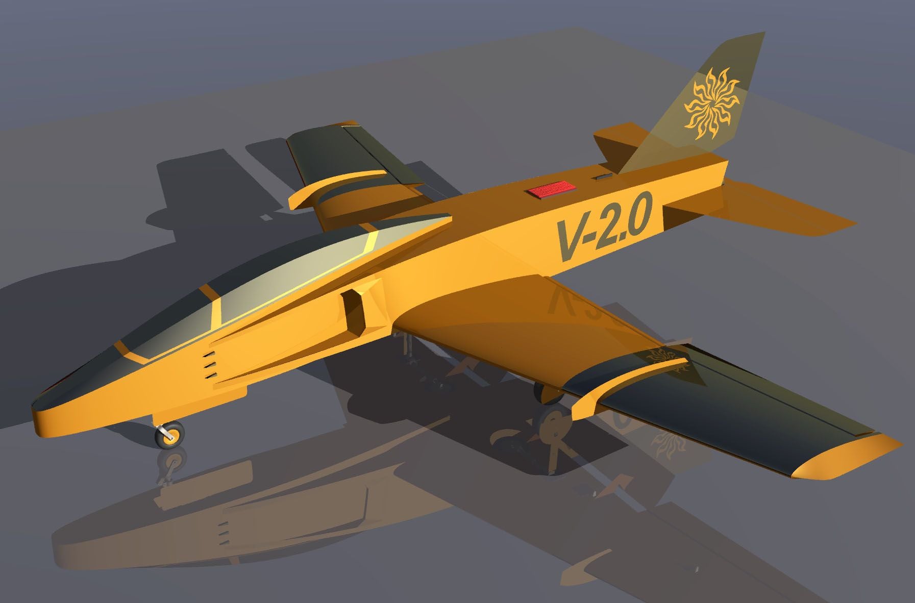
I got my laptop back from my son and now have access to my cad program after several years. It is a struggle relearning the process but here is the model, started a few days ago. It will have a 56" wingspan and is intended for simple wood construction. The flight goal is for it to be an easy to fly EDF since my flying skills are pretty average.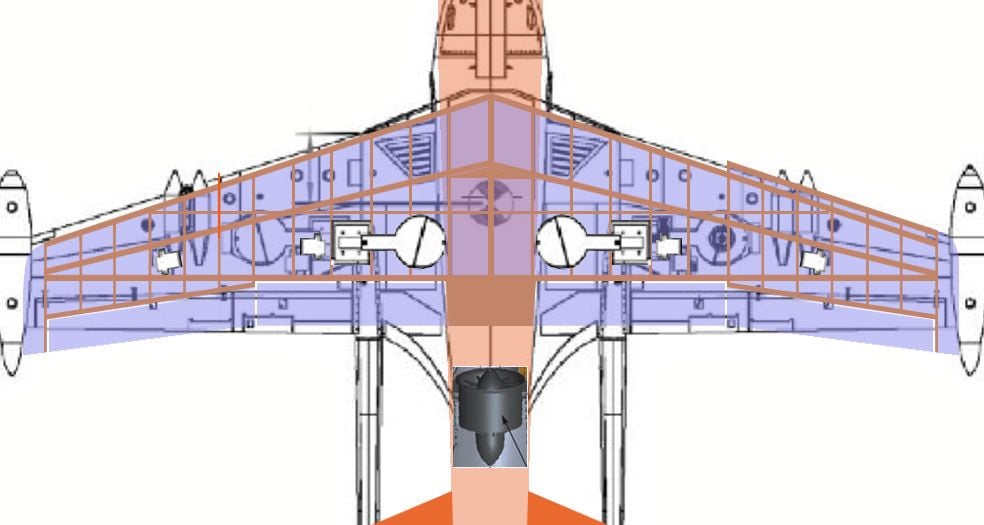
wing comparison to Venom model
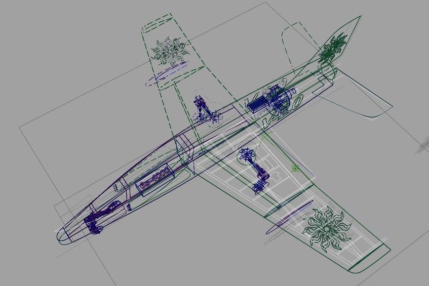
wire file
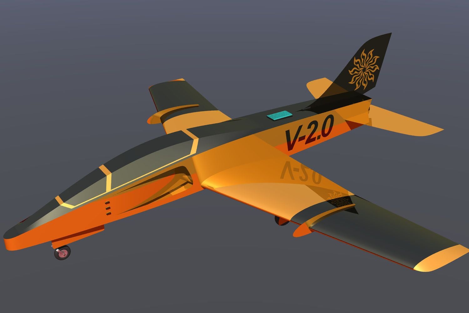
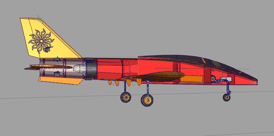
early rendering
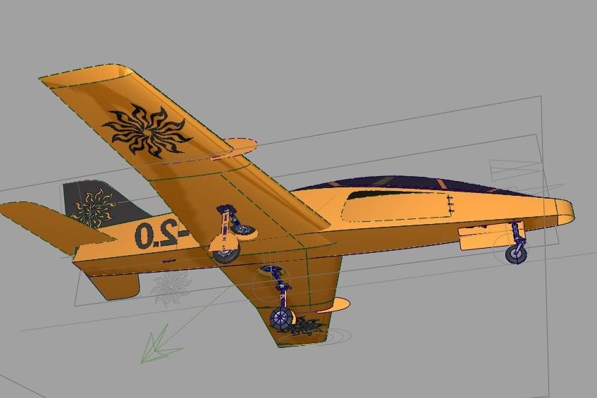
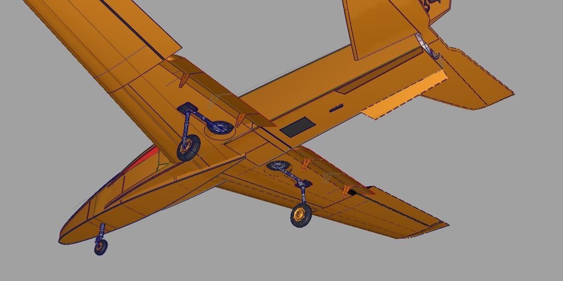
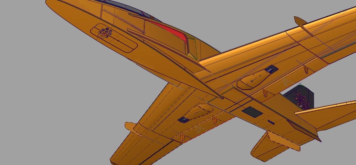
bottom view
early flaps/aileron study
I got my laptop back from my son and now have access to my cad program after several years. It is a struggle relearning the process but here is the model, started a few days ago. It will have a 56" wingspan and is intended for simple wood construction. The flight goal is for it to be an easy to fly EDF since my flying skills are pretty average.
wing comparison to Venom model
wire file
early rendering
bottom view
early flaps/aileron study
 08-23-2018, 05:39 PM
#3
Thread Starter
Here is a little more information on the project goals.The basic wing section is a NACA 2414. The center part is a scaled 2414. There is a small dihedral and a bit of washout. The fowler flaps will be used for low speed landing. Basic wing construction will be fairly conventional (D-tube).The fuselage will be very simple liteply construction – basically a top, bottom and sides. I am packaging the fan unit in as small a cross section as possible and front area will be considerably less than the Venom, or any other comparable EDF jet.
The performance goal is good, easy slow flight, with bursts of speed possible but not the norm.
The performance goal is good, easy slow flight, with bursts of speed possible but not the norm.
 08-29-2018, 03:58 PM
#5
Thread Starter
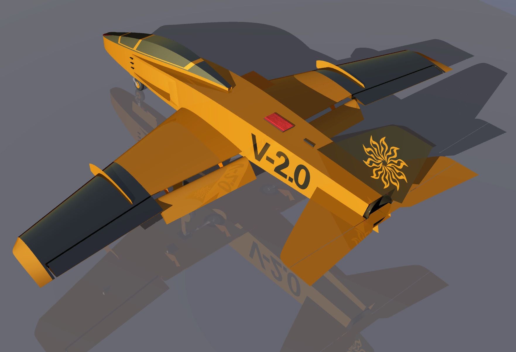
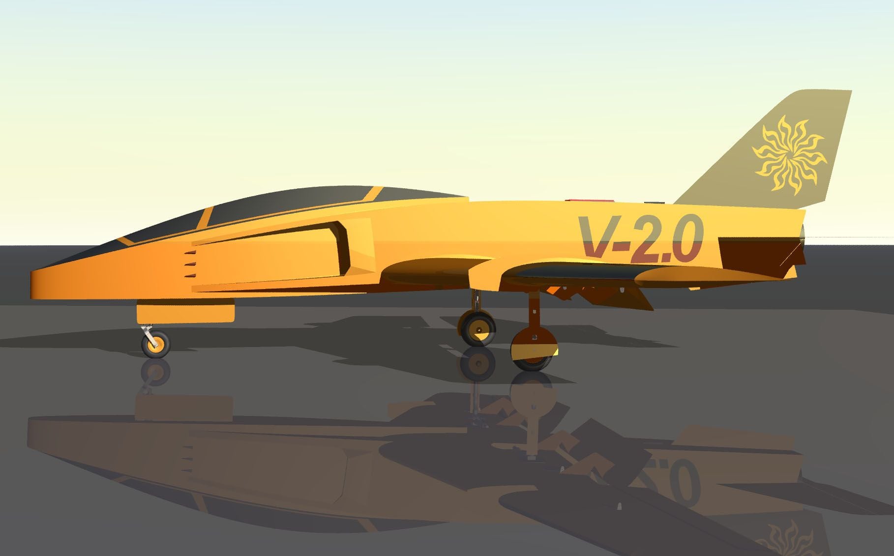
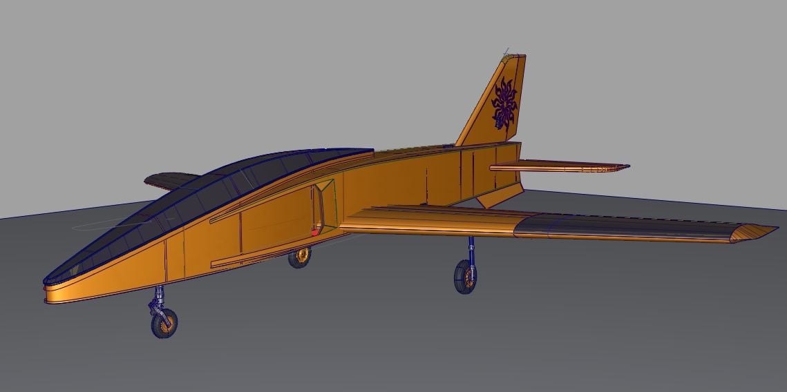
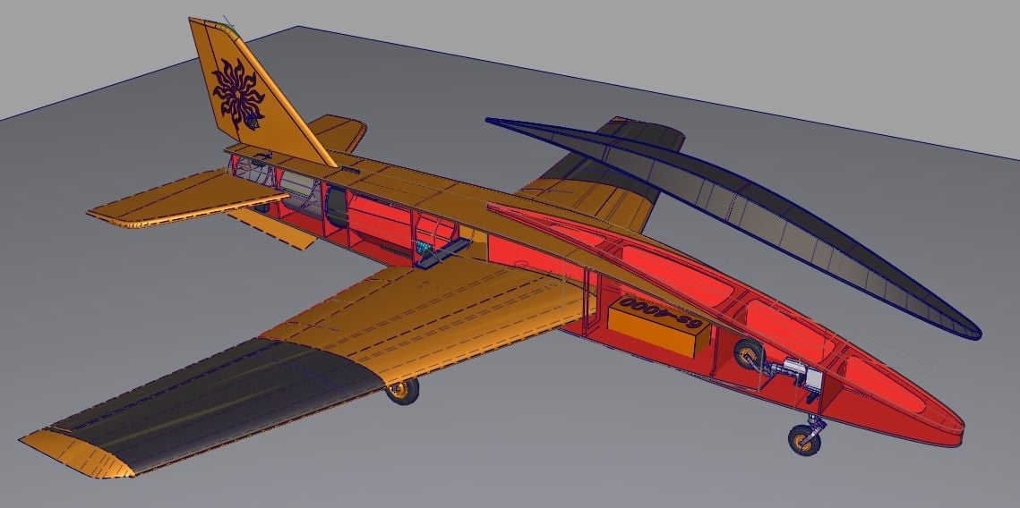
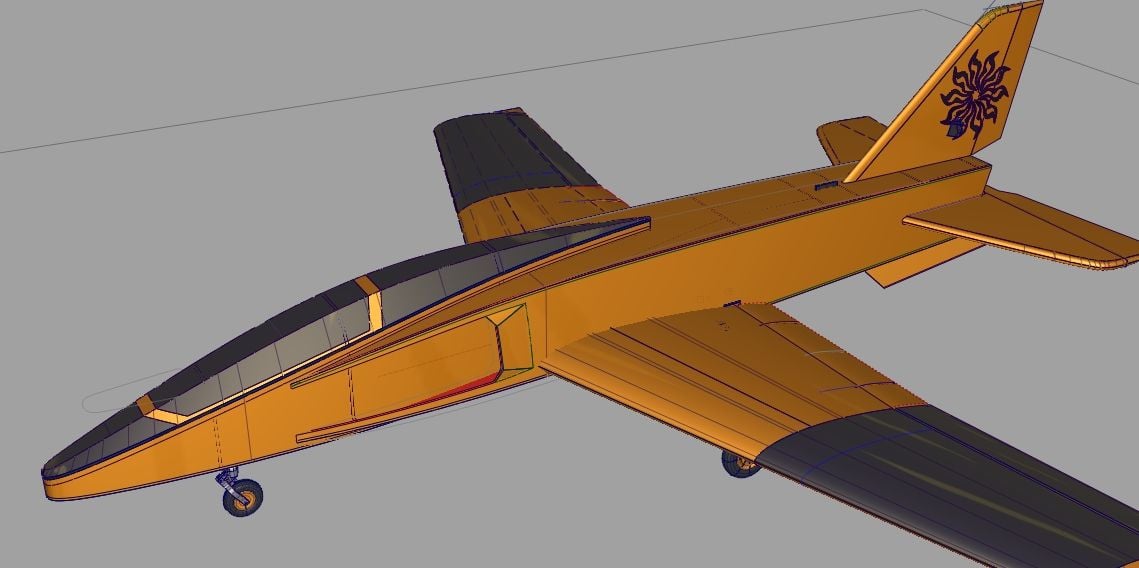
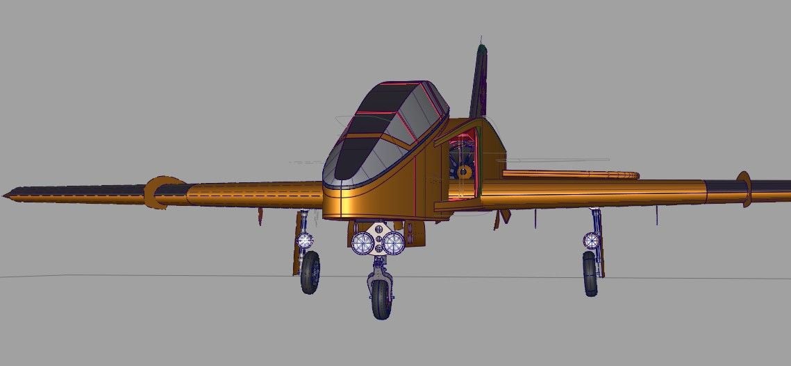
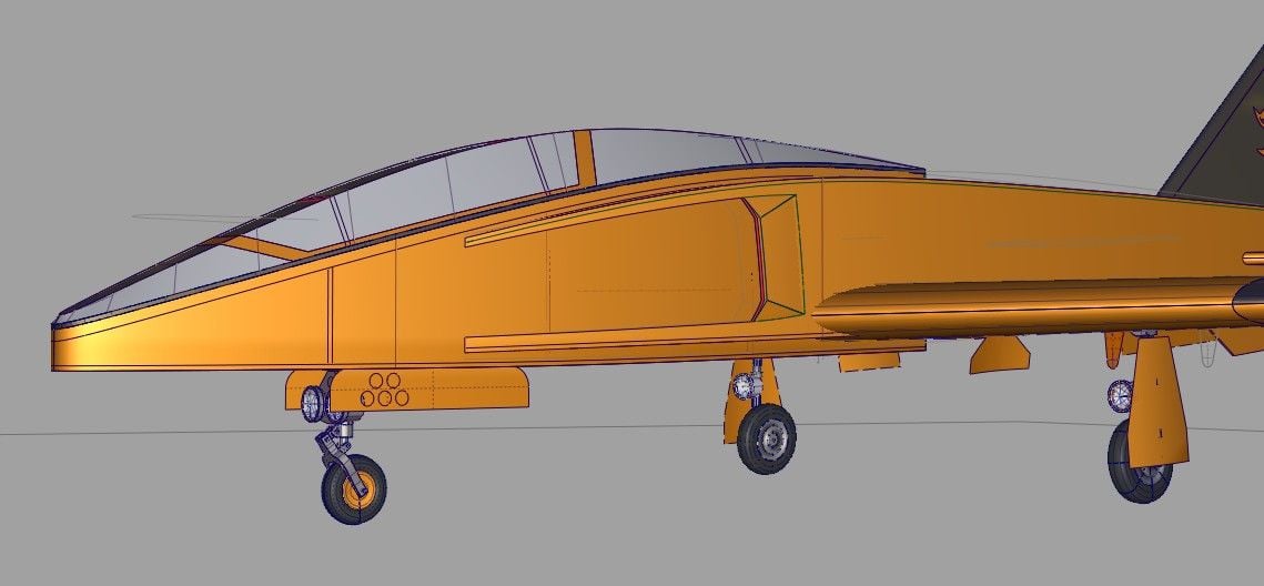
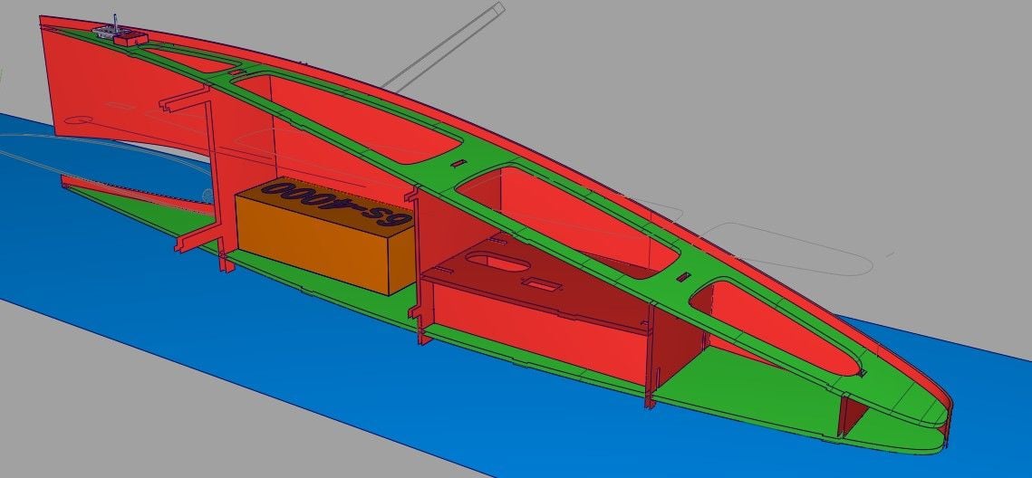
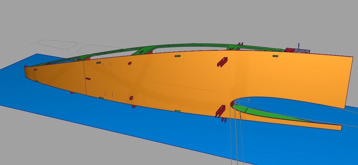
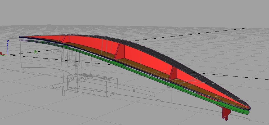
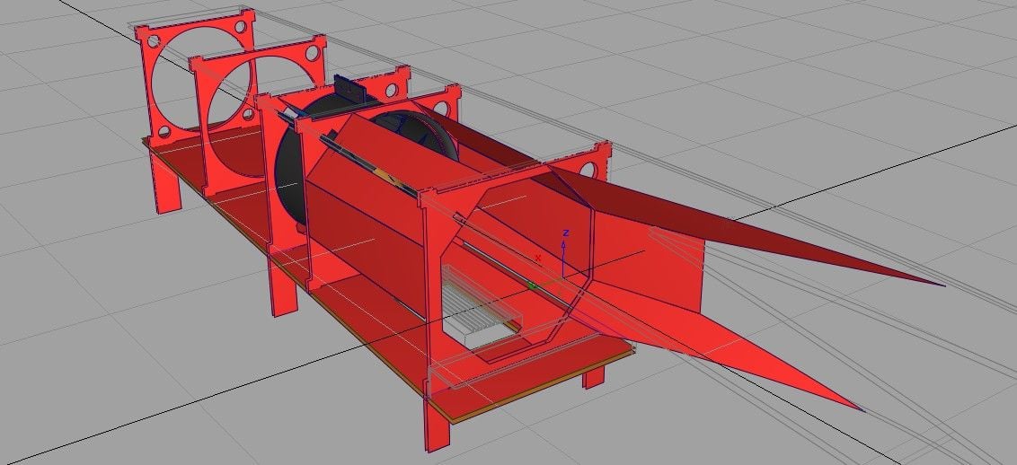
After struggling with the first version, I tried another look. This idea uses the interior ducting as inspiration for the exterior surfaces, making it a lot simpler to fabricate as well as more unusual looking. It has become much more angular. Now I am testing out the interior components and structure.

 09-12-2018, 03:52 PM
#8
Thread Starter
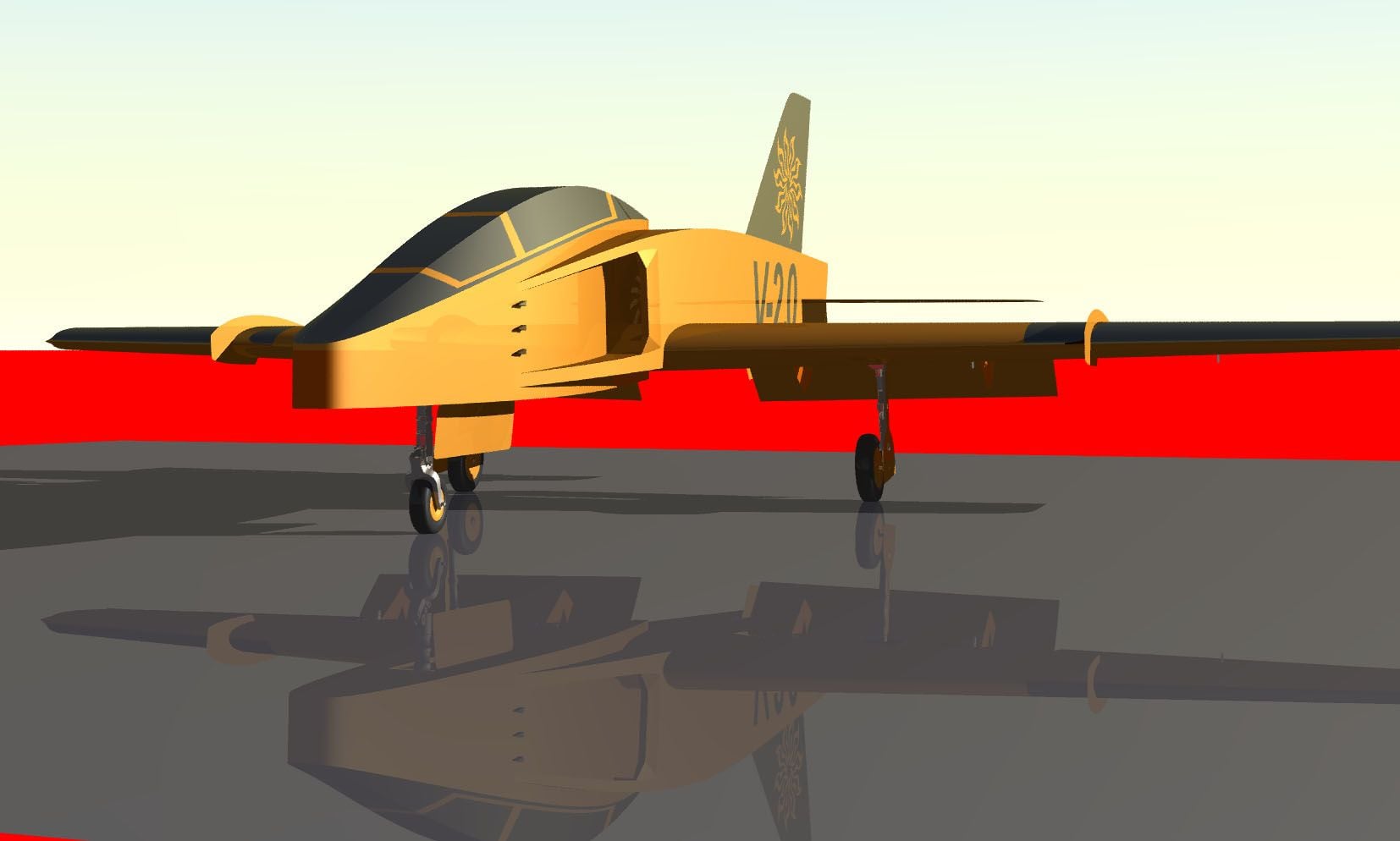
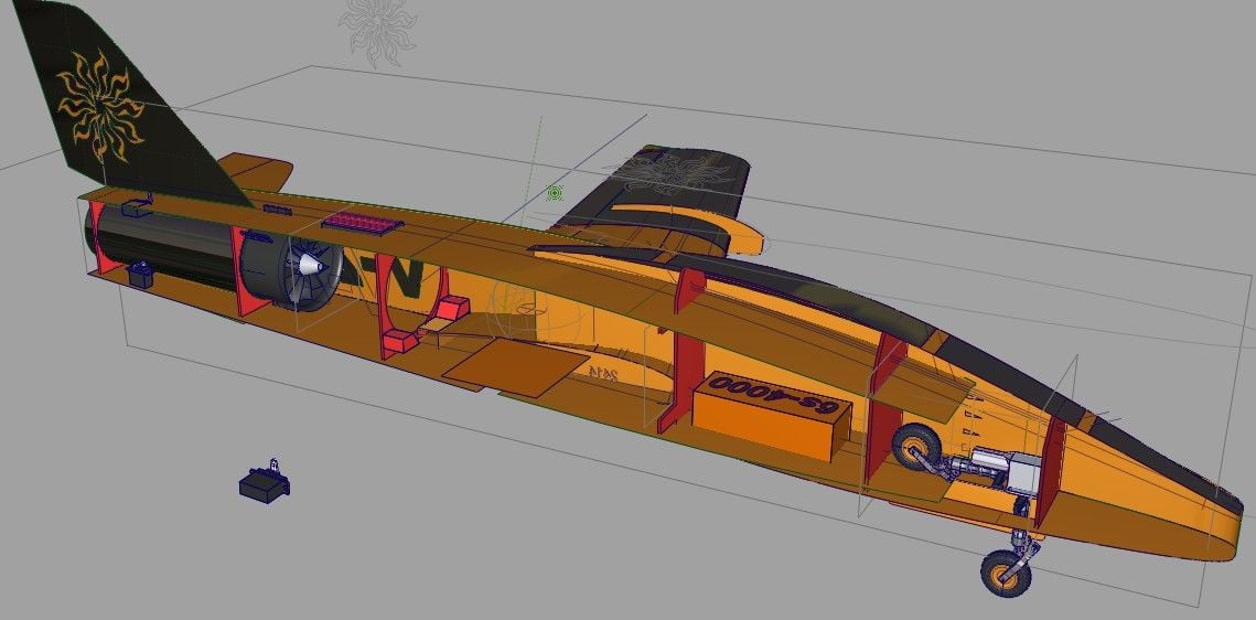
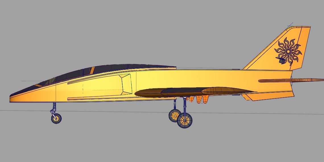
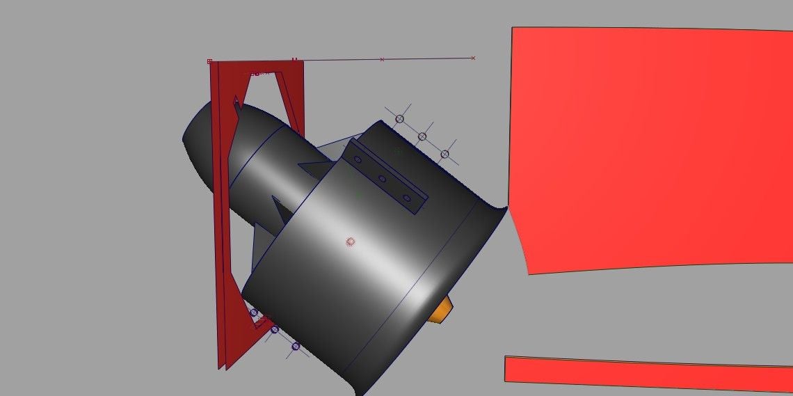
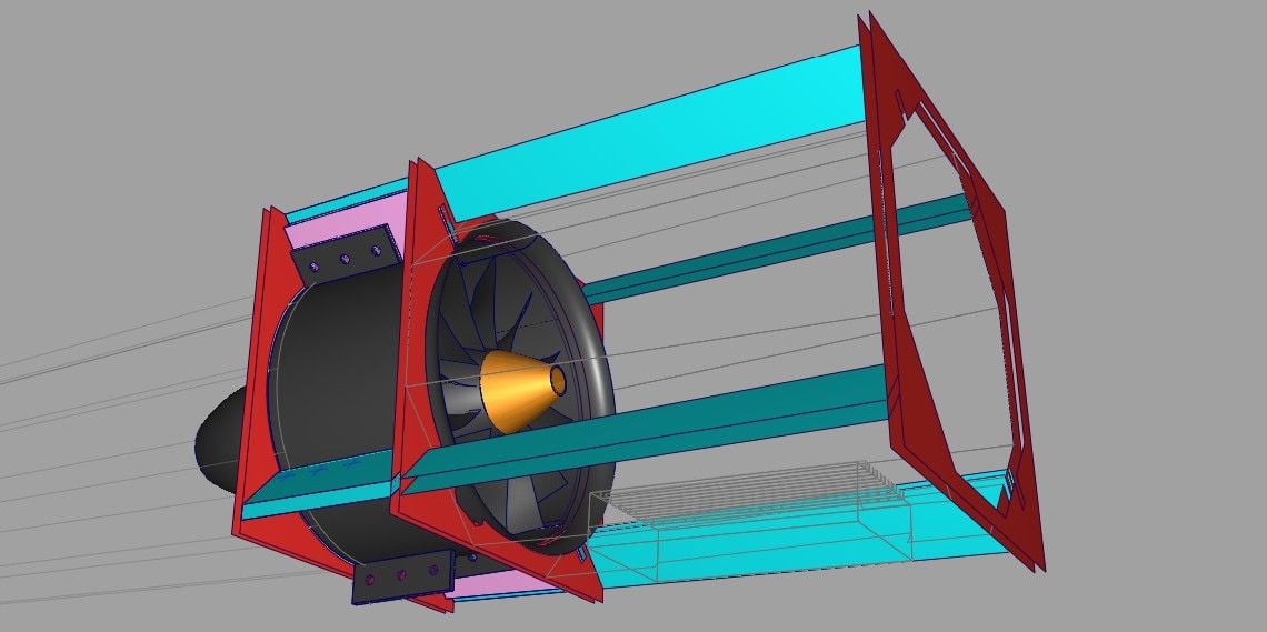
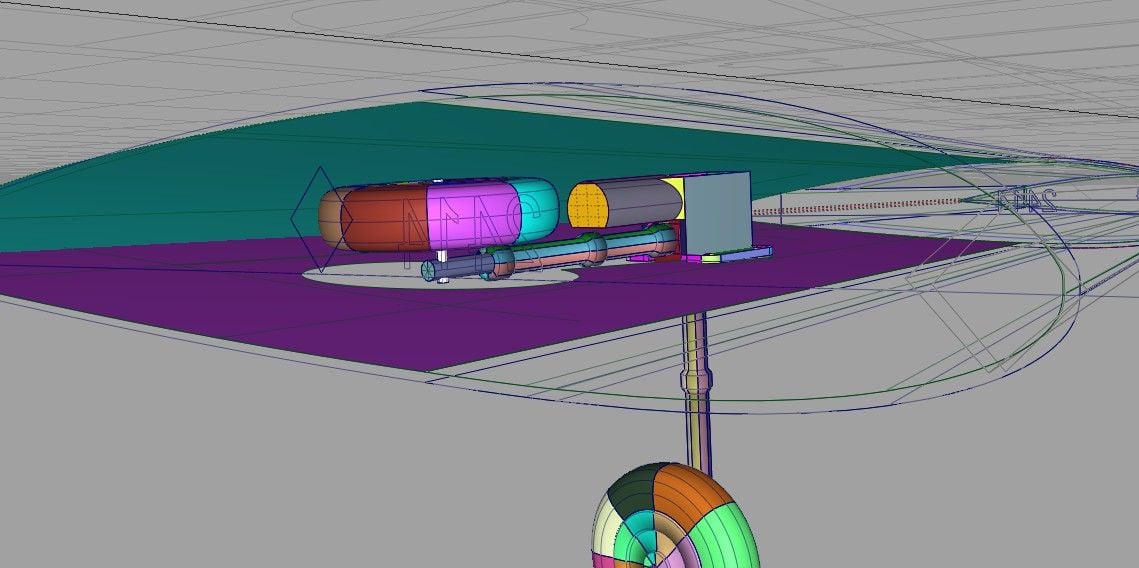
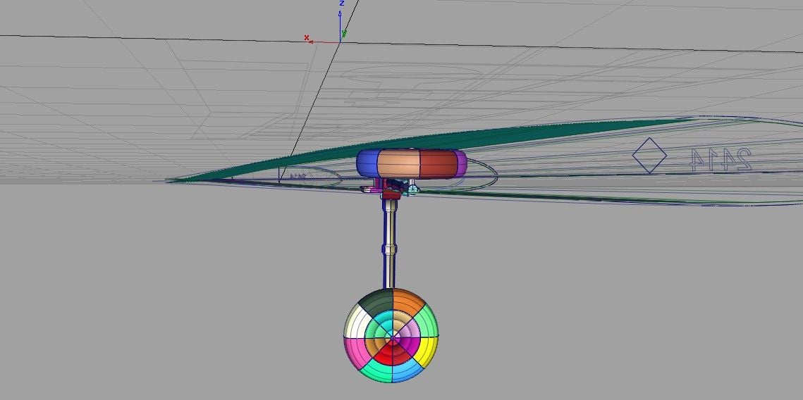
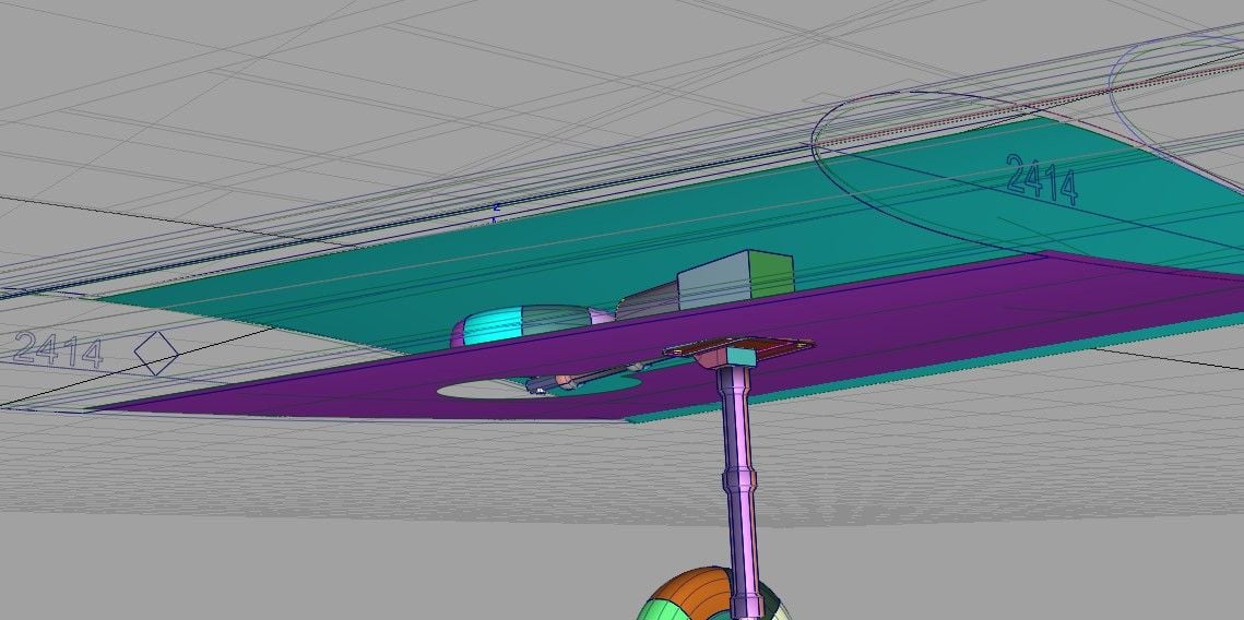
This is a tentative logo for my tail fin. Also, I have been working on the area around the nose gear installation, including the retract unit mounting blocks, etc. Another effort has been on the fan mount which is a little tricky due to the diagonal installation of the fan. The fan has to be installed through the wing mount area so I did an animation on how it can go in.

09-13-2018, 01:57 PM
#9
Thread Starter
Here is the nose gear retract pix which I forgot on the previous post.
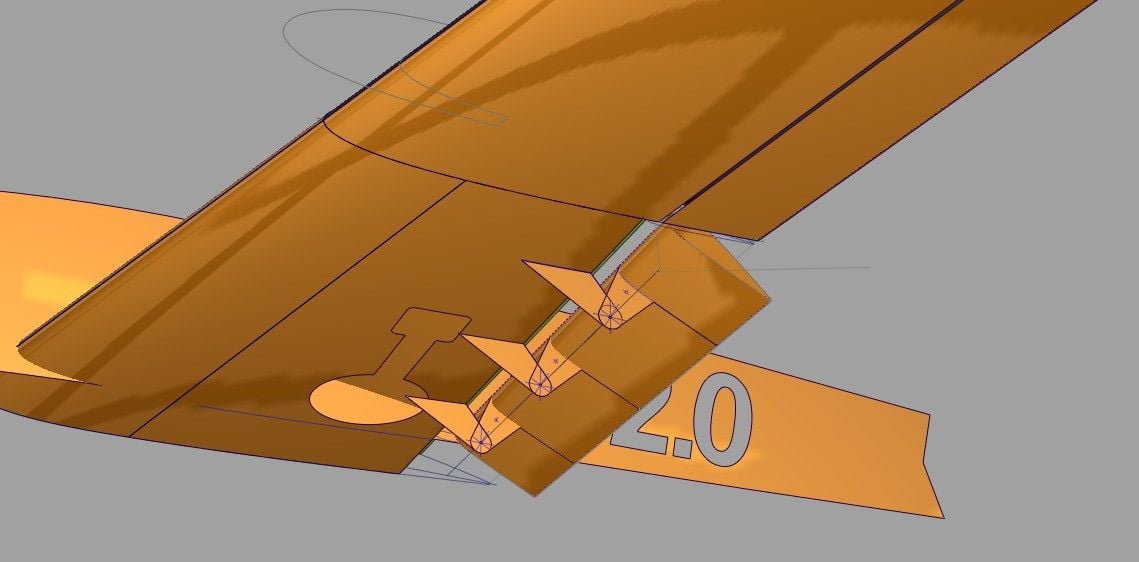
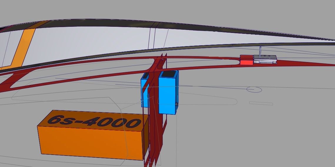
Also, this is a pix of the tail servos and the wing servos (less the aileron servo/not shown). The right wing servo powers the flap and the left one works the wing's air brake. The solution on the elevator servo necessitates use of a slim (expensive) sail plane wing servo
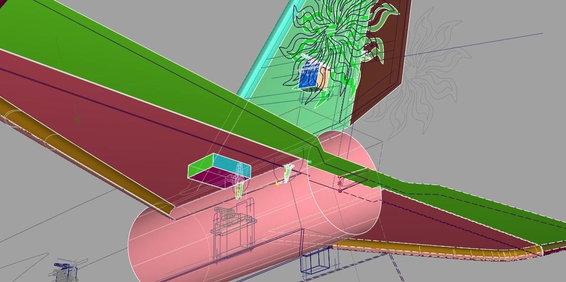

Also, this is a pix of the tail servos and the wing servos (less the aileron servo/not shown). The right wing servo powers the flap and the left one works the wing's air brake. The solution on the elevator servo necessitates use of a slim (expensive) sail plane wing servo
09-14-2018, 03:58 PM
#10
Thread Starter
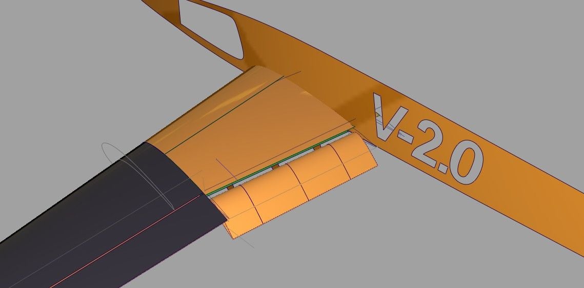
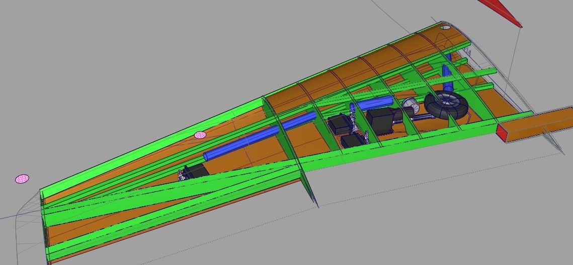
Another view of the two wing servos (rear one for flaps, front one for air brakes. Now how to hinge that airbrake surface?... 
(I don't bother trimmng down my servo arms on the CAD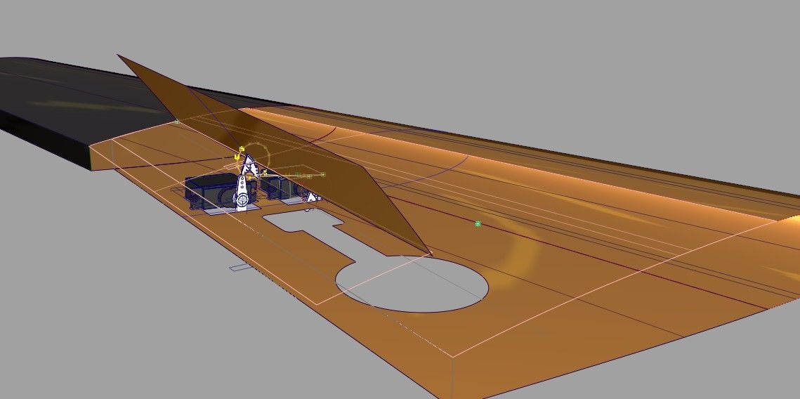
model - of course they would be on the real aircraft)
(I don't bother trimmng down my servo arms on the CAD
model - of course they would be on the real aircraft)
09-15-2018, 01:15 PM
#11
Thread Starter
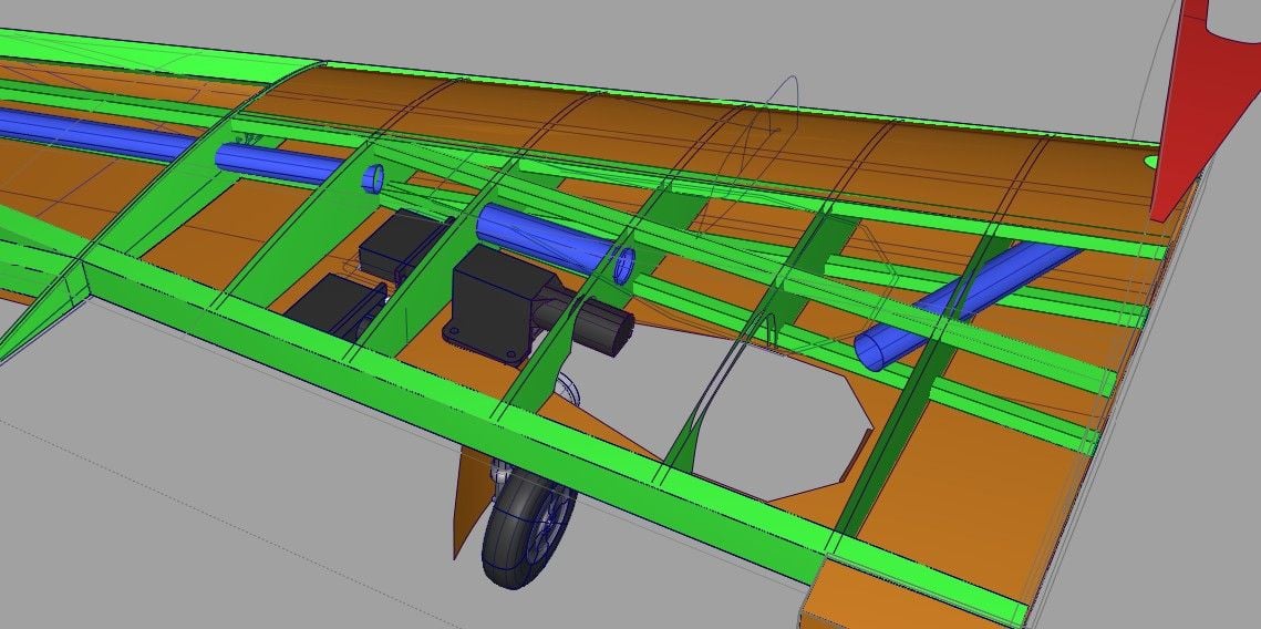
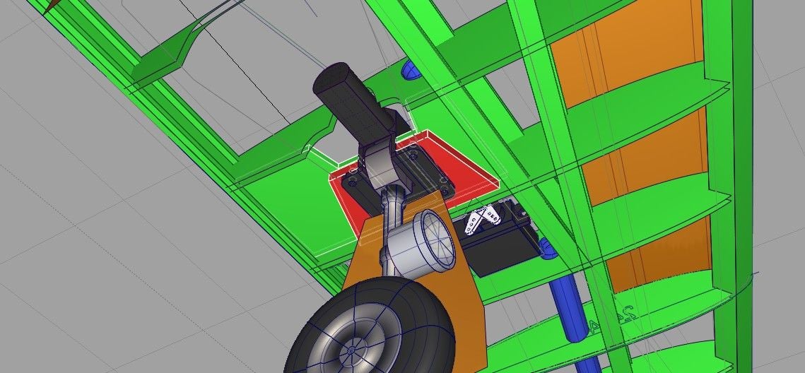
After making offset surfaces to account for the 1/16" balsa wing skins, I have been looking at a better location for the landing gear. I have moved it up a bit and tipped it - pretty much at absolute minimum tolerance now with the new LG location.
Last edited by allanflowers; 09-15-2018 at 01:17 PM. Reason: type placement
09-18-2018, 01:43 PM
#12
Thread Starter
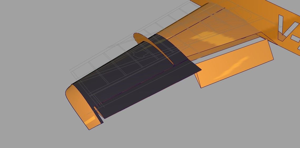
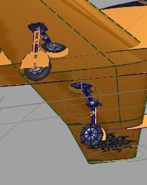
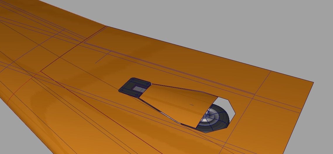
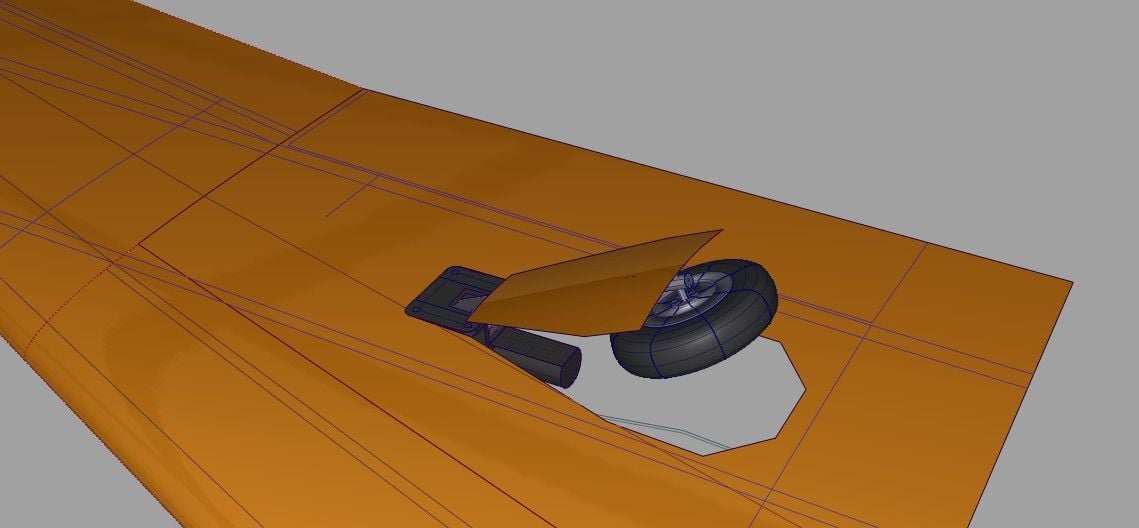
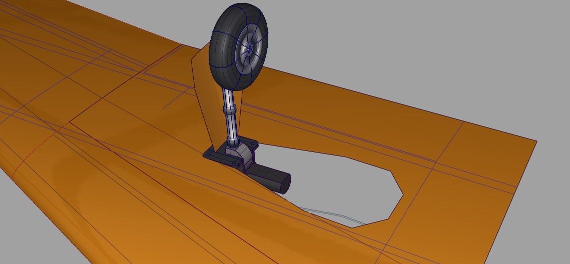
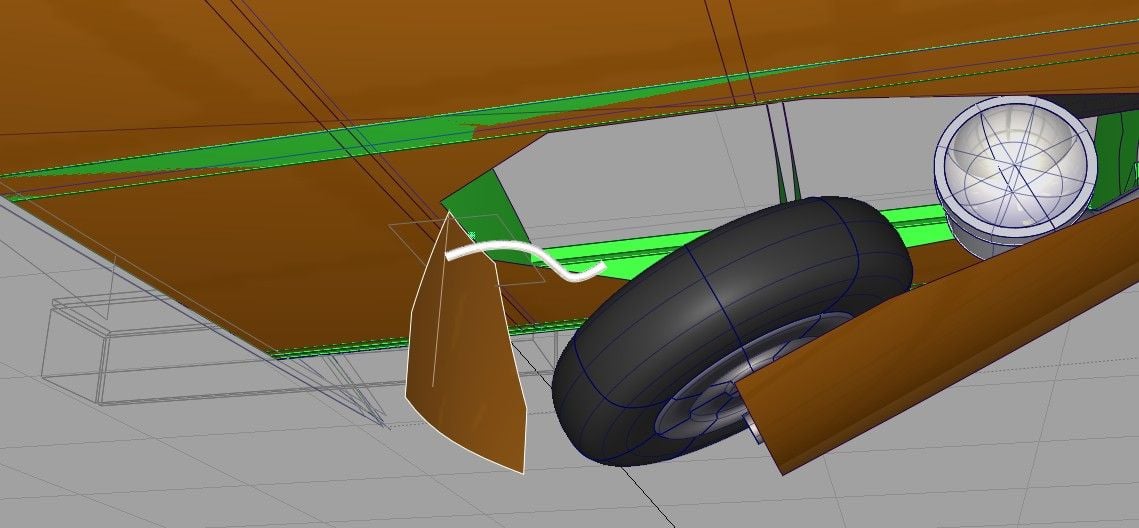
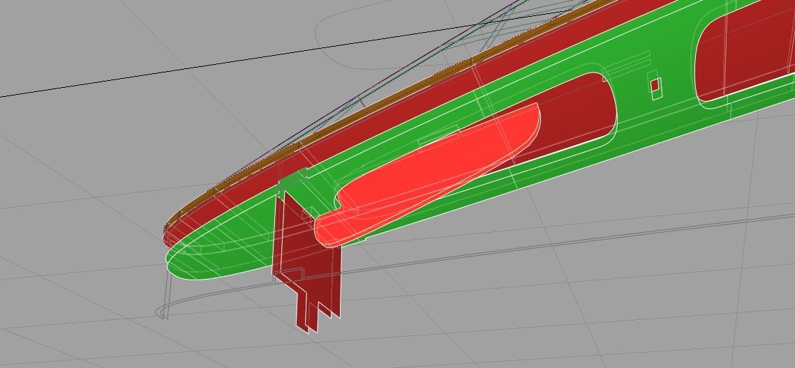
I was having problems getting the landing gear into this wing (naca 2414), which must be thinner than I realized. The small pix of the older model shows a conventional landing gear door shape – as well as the clearance problems with the landing gear strut, which is poking through the door.I was considering going to a thicker wing section to solve the problem but first decided to try a different SHAPE on the door and a little crown to the section. The last three pix are from an animation of this solution going through its 90 degree rotation. I am glad I tried this and think I will go this way.The shape is more consistent with the forms on the plane and the crown section looks good to me. The door would either be thin aluminum or 1/32 ply.
09-20-2018, 05:25 PM
#13
Thread Starter
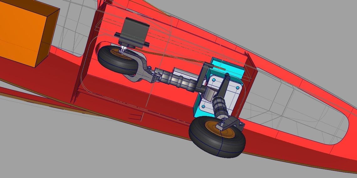
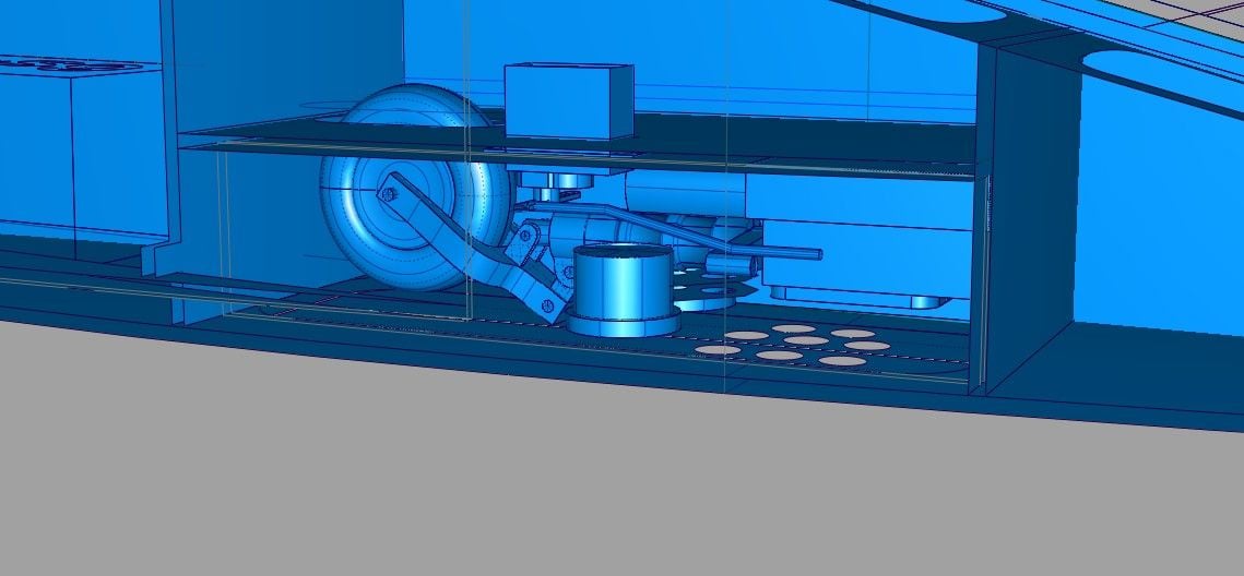
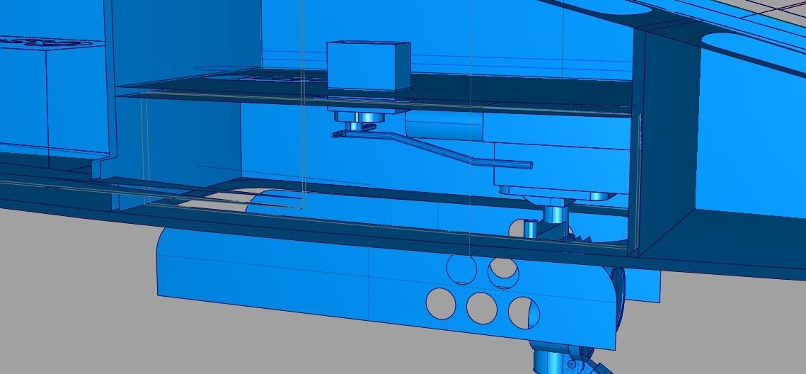
I'm working on the nose gear area design, including the doors. I thought it would be cool to use some LED landing lamps that come down on the gear struts. This makes the packaging in the nose gear bay very tight but it looks possible, after a lot of fussing around moving components.
09-28-2018, 03:29 PM
#14
Thread Starter
Several cad studies: First is the canopy latch workout. Then the beginning of the wing build exploration, including some ideas on wiring tubes to carry the leads from the various wing functions to the forward inboard section of the wing where the wires would be routed out to the fuselage.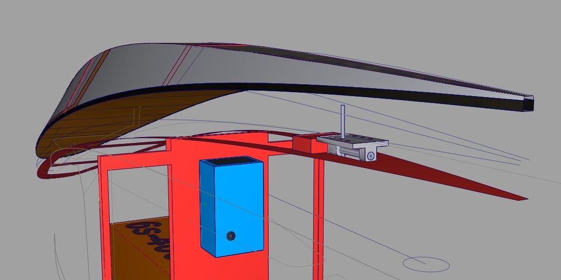
10-04-2018, 03:27 PM
#15
Thread Starter
I have been working on the wing construction design. First is the mounting for the main landing gear, two plates, one in lite ply, the other is 3/16 ACply. Second is working out a way of articulating the inner gear door with a little kicker bar, powered by the tire as it closes. Last is the creation of the ribs on the wing outer half.None of this is final because any tabs or slots will have to be worked out later. Still it is important to be able to get tentative solutions and see how everything works together.
11-04-2018, 06:19 PM
#16
Thread Starter
This project is temporarily on hold since I have recently moved to a new house and there is much to do. Also, my son has borrowed my computer for a while and that cripples me design wise. Hopefully I can get going again in a month or so.
08-16-2020, 12:36 PM
#17
Thread Starter
I finally have the laptop with my CAD program back from my son and I hope to return to this project. This has taken a little longer than I expected
First step is to re-familiarize myself with the program (very rusty!) and the model as far as it had been taken. All the old files have to be found, among a ton of car and model plane projects going back several decades.
First step is to re-familiarize myself with the program (very rusty!) and the model as far as it had been taken. All the old files have to be found, among a ton of car and model plane projects going back several decades.
08-17-2020, 12:56 PM
#18
Thread Starter
It is a struggle getting back into this.
I am reconsidering my wood/materials choices. In the past, I could find almost anything I wanted, either on line or at the local hobby store. Now, it seems like the choices (from most easy sources at least) are limited on size options, particularly sticks. I don’t blame the companies but need to resolve these choices before investing a lot of time on CAD.
I am checking Sig, Tower, National and Balsa USA to see what they have on hand. Another option, one I am loathe to consider, is the use of Fliteskin for sheeting. This runs contrary to the idea of this model being a light & easily built plane using conventional methods - but certainly is a strong and durable option. The weight, at about 20oz per 3x4 sheet in .007 material, is not good either. Cost is also a problem. Still, it is good to learn new things and its strength and hardness is difficult to argue with.
In the mean time, I am going through my files, discarding duplicates or outdated ones. Also I am trying to deal with mm vs inches. I have always worked with mm’s on my job but material (wood) sizes are easier to understand in inches.
08-18-2020, 11:36 AM
#19
Thread Starter
Having worked through the inches vs mm's and available wood size, my current focus is now on the aircraft tail. I am working to create the line drawing to build over, for the fin/rudder and stab/elevator. These are not laser cut parts but a drawing will be needed.
My cad “station” is a Dell laptop running Alias software – kinda slow but with a good
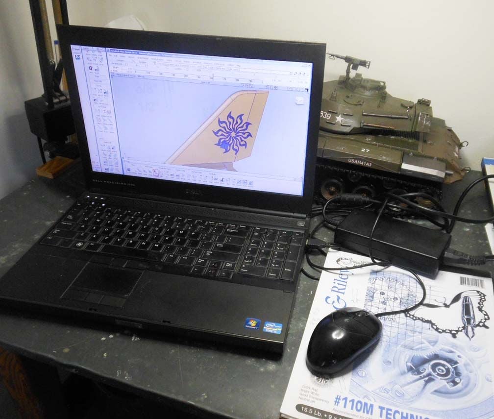
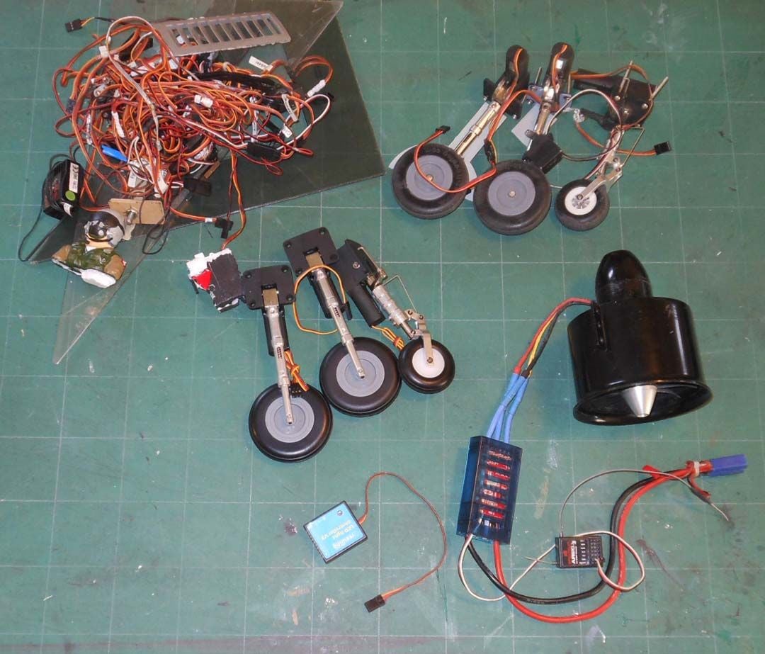
graphics card. The other pix is of the parts recovered from the foamie Venom – primarily the fan and retracts (I got new ones) and a lot of misc. stuff.
My cad “station” is a Dell laptop running Alias software – kinda slow but with a good
graphics card. The other pix is of the parts recovered from the foamie Venom – primarily the fan and retracts (I got new ones) and a lot of misc. stuff.
08-24-2020, 02:26 PM
#20
Thread Starter
This is some work generating lines for the tail surfaces which will be conventional balsa structures. A lot yet to do on this drawing.
Also I am working on the front part of the fuselage to created the laser-cut parts -with tab/slot construction.
Most of my time at this stage is getting back up to speed on the software and existing files.

Also I am working on the front part of the fuselage to created the laser-cut parts -with tab/slot construction.
Most of my time at this stage is getting back up to speed on the software and existing files.
08-26-2020, 01:41 PM
#21
Thread Starter
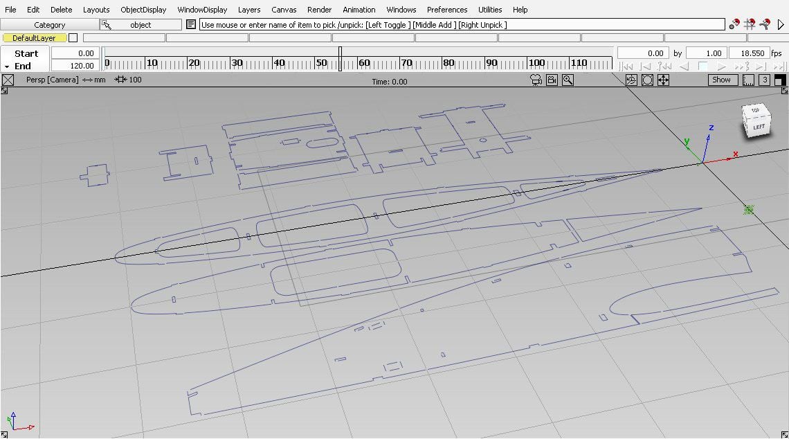
These are the laser cutting lines for the forward fuselage parts, laid out flat. I have introduced the gaps in the lines that should keep the parts from falling out. All lines are polylines, to cut predictably. I hope I am remembering the requirements for laser cutting. It has been a few years since I did this kind of thing.
Last edited by allanflowers; 08-26-2020 at 01:48 PM.
08-27-2020, 02:05 PM
#24
Thread Starter
I am working on the canopy, which has become a little more complicated than I wanted, in order to get the right look. First pix is the tongue which constrains the forward end (the rear latch was shown earlier). The second pix is a general view of the canopy and its internal structure.
08-29-2020, 11:23 AM
#25
Thread Starter
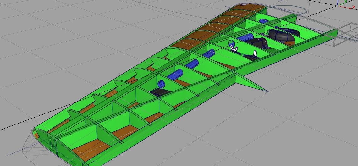
I have reduced the forward surfaces to poly lines and am onto the rear fuselage. Here are the formers in that area which have been recreated with tabs. Slots are yet to do. These formers are the mounts for the fan and thrust tube, plus some general internal baffles to provide good internal flow. Three of them also have "feet" to support the assemble during construction.

Last edited by allanflowers; 08-29-2020 at 12:19 PM. Reason: add photo