


Gas airboat project
 08-20-2014, 09:30 AM
#1

Thread Starter
Join Date: Mar 2009
Location: Zeeland, MI
Posts: 30
Likes: 0
Received 0 Likes
on
0 Posts
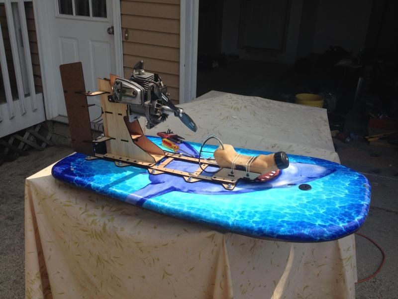
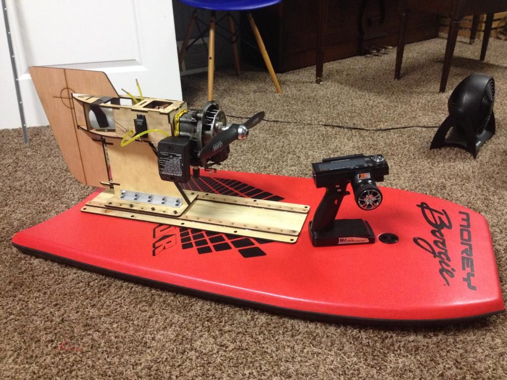
Hey everyone, I am working on a gas airboat and would like some input and help on it. I have already built my first revision on a boogie board just to build something fun and get going. Below is a picture of what I have. I started with a homelite 25cc engine which is stock (haven't even machined the flywheel or casing) I went to the local hobby shop and bought a 14" prop as that was all they had and then laser cut a plywood frame and structure to mount it all to the boogie board. I built it in about 4 hours total time so its rough but it works really well on land. notice I said land. Here is the first question of many.
I bathtub tested it and it sat pretty level so I put it in a pond. Once on the throttle all it wanted to do was bury the back of the boat and lift the bow. First off, does the board even look large enough for the weight of the engine thats on it? its about 2" thick, 16" wide and 40" long. If thats fine, what should I do next? move the engine forward? I also have the engine mounted straight vertical to the hull, does it need to be shimmed at angle to work better? I built a ladder rail system on the boat so I can easily move the engine forward. You may also notice that I mounted the electronics up high behind the engine. I did this so everything was self contained in the engine mount so it could move without having to redo all my linkages. Was that a poor decision from the weight aspect? I have two standard sized servos, very small receiver and battery pack up there. is that too much rear weight?
next question, prop size. From what I have been reading, I may have too small of a prop for this engine. looks like a 16x6 or 16x8 may be better. thoughts?
This boat was really a proof of concept. I have started to build a engine mount that is similar to that of the dumas windy airboat. I like the look and single rudder setup. Would it be fine to continue mounting all the electronics up high behind the engine or should I move those lower. I would also like to get a smaller RC plane tank mounted on the engine stand too so its a self contained "power pod" that I can move between different hulls. Good, Bad?
So yeah, lots of questions. if you are still reading this, thank you. Any input would be great here. I'm just having fun with it, but would like to stay on the right track to end with a fun boat that is functional.
here is a youtube video of the boat in its current state
https://www.youtube.com/watch?v=MN_6...ature=youtu.be
I bathtub tested it and it sat pretty level so I put it in a pond. Once on the throttle all it wanted to do was bury the back of the boat and lift the bow. First off, does the board even look large enough for the weight of the engine thats on it? its about 2" thick, 16" wide and 40" long. If thats fine, what should I do next? move the engine forward? I also have the engine mounted straight vertical to the hull, does it need to be shimmed at angle to work better? I built a ladder rail system on the boat so I can easily move the engine forward. You may also notice that I mounted the electronics up high behind the engine. I did this so everything was self contained in the engine mount so it could move without having to redo all my linkages. Was that a poor decision from the weight aspect? I have two standard sized servos, very small receiver and battery pack up there. is that too much rear weight?
next question, prop size. From what I have been reading, I may have too small of a prop for this engine. looks like a 16x6 or 16x8 may be better. thoughts?
This boat was really a proof of concept. I have started to build a engine mount that is similar to that of the dumas windy airboat. I like the look and single rudder setup. Would it be fine to continue mounting all the electronics up high behind the engine or should I move those lower. I would also like to get a smaller RC plane tank mounted on the engine stand too so its a self contained "power pod" that I can move between different hulls. Good, Bad?
So yeah, lots of questions. if you are still reading this, thank you. Any input would be great here. I'm just having fun with it, but would like to stay on the right track to end with a fun boat that is functional.

here is a youtube video of the boat in its current state
https://www.youtube.com/watch?v=MN_6...ature=youtu.be
 08-20-2014, 12:10 PM
#2
Senior Member

Join Date: Dec 2013
Posts: 432
Likes: 0
Received 0 Likes
on
0 Posts
I have to say that moves pretty good on land WOW! For water and bare in mind I've not built one of these but I'd suggest moving the engine forward to approx 1/3 up on the board which by the look of it shouldn't be too hard. You should probably try to get rid of any excess weight on the engine as well as move the radio and batteries up to around where the fuel tank is. It looks like a single high rudder and you may benefit from a double rudder assembly, at least that is what I've seen others do. Ordinarily you should be in the area of twice the width of the engine height for proper stability so lightening things up will be a definite asset. I have seen other boards of similar design so you may want to hunt one of the builds down and see what they've proven in their design to help you along. Great fun though 
08-20-2014, 02:47 PM
#4
Senior Member

Join Date: Aug 2013
Posts: 444
Likes: 0
Received 0 Likes
on
0 Posts
Hehe, love these gassers, looking forward to mine one day
I'm going to say the opposite and suggest adding weight to the front rather than losing any. The reason being totally unproven but a hunch. A lot of boogie board boats seems to suffer from serious porpoising, with the hull weight being so low the CoG will be higher than many boats, so to me to counter your nose up attitude and to aid lowering the CoG add ballast. It may prove to be quite a bit, but to start with I'd arrange for enough weight for the boat to float dead level. I have to believe that it's stern down right now, but it'll take a bit of weight to really true it up, looking at the hull I reckon we need to displace around 1 to 1.5 additional litres of water, which is only a nose drop of say 5 degrees.
I would move the radio, it could be used on the front to be part of that weight if the throttle linkage is doable, that bring down the CoG a bit more too.
Your prop size proposals fit with other folks I seen.
Looks like great fun, and good to have another active builder amongst us!
EDIT: btw that's laser cut ply?
08-28-2014, 08:37 AM
#5
Thread Starter
Join Date: Mar 2009
Location: Zeeland, MI
Posts: 30
Likes: 0
Received 0 Likes
on
0 Posts
yes it is laser cut ply. Its cheap luaun plywood. costs about $8 for a 4x8 sheet. works great for prototyping ideas. also, if its damaged, its cheap to rebuild.
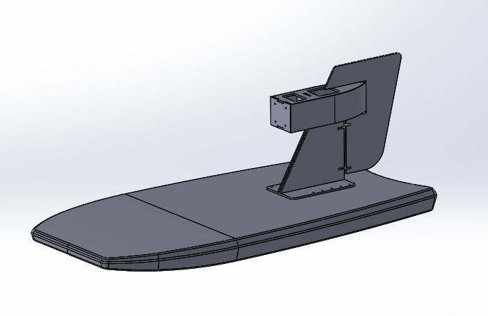
I have continued on my new design. Its a single rudder designed after the dumas windy air boat. I think pictures will explain it the most so here we go.
here is the cad design for it:
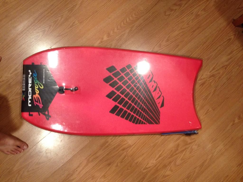
New board ($20 at a local store, great board for the price)
Fast forward to the engine "power pod" all glued, bolted and put together.
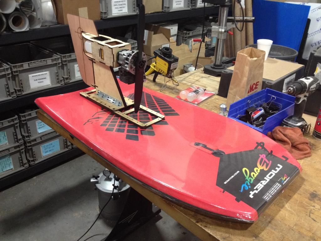
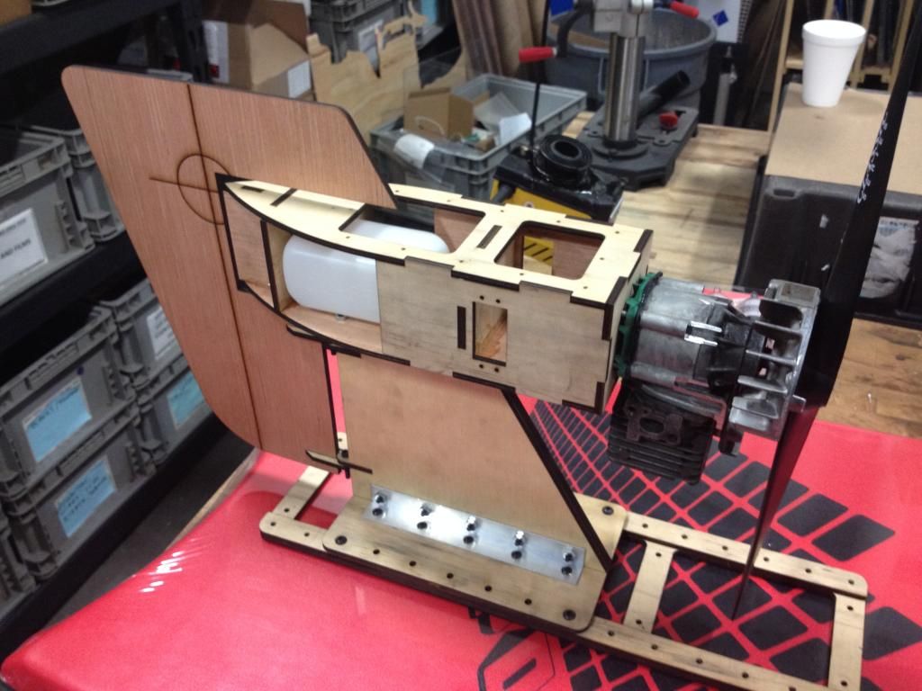
Thats about it for now. hope to get the electronics setup in the next few days.
Justin
I have continued on my new design. Its a single rudder designed after the dumas windy air boat. I think pictures will explain it the most so here we go.
here is the cad design for it:

New board ($20 at a local store, great board for the price)

Fast forward to the engine "power pod" all glued, bolted and put together.


Thats about it for now. hope to get the electronics setup in the next few days.
Justin
08-28-2014, 10:43 AM
#6
Senior Member
Join Date: Dec 2013
Posts: 432
Likes: 0
Received 0 Likes
on
0 Posts
That is awesome well done, especially the lower mount base with the ease in which you can move the engine mount fore or aft. I'm considering doing a board myself this winter but with a glow engine, one way to beat the winter blues tearing up a few snow banks! The only suggestion I have and this is only from what I can tell from the pic is the center section of the mount with minimal support, you may have to add a bracket up on an angle from the base up to the center top for strength. WELL DONE!
08-28-2014, 11:32 AM
#7
Thread Starter
Join Date: Mar 2009
Location: Zeeland, MI
Posts: 30
Likes: 0
Received 0 Likes
on
0 Posts
Thanks Arcdude! I think I understand what you are saying about the support. I agree, it may need some better support for the top. I built it more on style than total support (I'm a designer after all, just work with engineers) so I went more for aesthetics. Probably more than I should have. The joy of it is that this is all easily cut from cad files on a laser so I can always redesign, cut, glue and have something completely different in a day. and Since I have it all based on a rail system, it can easily be mounted to the board without too much modification.
Still trying to come up with a good method of attaching the rail system to the board. the first prototype was bolts top to bottom but I'm not crazy about that. Has anyone had luck gluing wood to the boogie boards? I know they make some adhesives that are made for foam. Any input on that would be great.
I also had to turn the carb 180 degrees so I need to work on taping the crank case to add a pressure line to the carb. That way it doesn't matter the orientation on the intake. I also want to skin the sides of the fuselage at some point but I may wait for that till I have proved everything else out.
Justin
08-28-2014, 01:23 PM
#8
Senior Member
Join Date: Dec 2013
Posts: 432
Likes: 0
Received 0 Likes
on
0 Posts
Hey Justin, One consideration I've considered when I get around to mine is to router out a couple of grooves for a good portion of the length and insert a few hardwood pieces into them to attach to, gorilla glue I'm finding to be quite a good adhesive and safe for foam. The only caution with Gorilla glue is it's tendency to foam up if one isn't cautious with how much they use, you just have to babysit the project a while and wipe off any excess as it oozes out of the cracks.
08-28-2014, 03:17 PM
#9
Senior Member
Join Date: Aug 2013
Posts: 444
Likes: 0
Received 0 Likes
on
0 Posts
Looks great. love it!
I'd imagine the way to go with bonding the mechanicals to the board would be to load spread. That board material is not good in tensile load so the more surface area and more spread out it is the better. Perhaps partially sheeting it with ply would do well?
I'd imagine the way to go with bonding the mechanicals to the board would be to load spread. That board material is not good in tensile load so the more surface area and more spread out it is the better. Perhaps partially sheeting it with ply would do well?
08-28-2014, 03:53 PM
#10
Thread Starter
Join Date: Mar 2009
Location: Zeeland, MI
Posts: 30
Likes: 0
Received 0 Likes
on
0 Posts
The rail system that is in the photo was an old one. I could make a new one that the base piece has a larger surface area and maybe give that gorilla glue a try. That would give a large surface area for the glue to bond.
Not a ton more, but I did get the engine mounted up a little better to see how the exhaust and carb all fit on. You can also see the custom prop shaft I turned.
A few questions. Is there any reason I can't add a "Z" bend to the throttle and rudder linkages? The servos won't be quite in line for all the linkages.
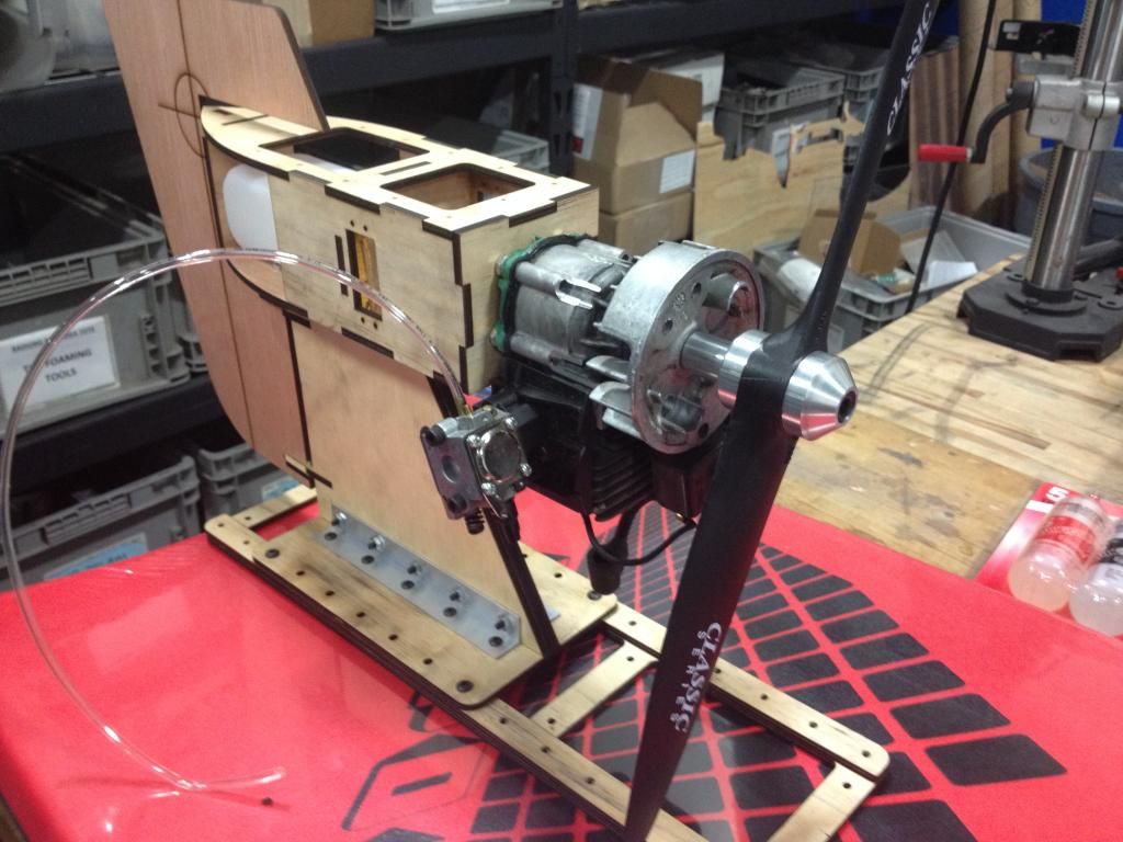
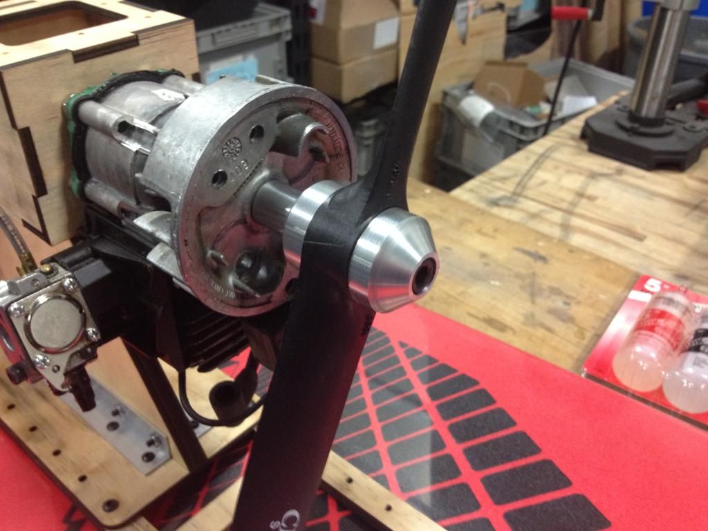


 08-28-2014, 05:04 PM
#11
Senior Member
Join Date: Dec 2013
Posts: 432
Likes: 0
Received 0 Likes
on
0 Posts
I'd consider a bell crank or something similar for the rudder to get as straight a line as possible the stress's will be considerable and you don't want any flex there. The other option for the throttle is to use a flex cable that'l suit just about all situations.
A side note, I'm afraid I'd have to agree with Jeremy_H the wood kind of bothers me a little as well, with the kind of torque your putting through the prop I'd hate to see it go airborne.
A side note, I'm afraid I'd have to agree with Jeremy_H the wood kind of bothers me a little as well, with the kind of torque your putting through the prop I'd hate to see it go airborne.
Last edited by arcdude; 08-28-2014 at 05:13 PM.
08-28-2014, 06:36 PM
#12
Thread Starter
Join Date: Mar 2009
Location: Zeeland, MI
Posts: 30
Likes: 0
Received 0 Likes
on
0 Posts
What about the wood and where? For the rail system that attaches to the board? what if I used a large piece and laminated a few different layers together to beef it up?
08-28-2014, 07:06 PM
#13
Senior Member
Join Date: Dec 2013
Posts: 432
Likes: 0
Received 0 Likes
on
0 Posts
I also believe the base should be wider and the center upright should have a triangle or square type base up to at least the bottom of the engine mount, even if it initially seems sound through time it will weaken because of the torque of the engine. As it sits right now all of the forces are being directed directly at the angle aluminum at the base and the material immediately around it you need to distribute the load. Your engine mount styling in the first pic would be a better bet. Bare in mind we are only going by what we can discern from the pics. What type of wood is the mount made of? Is there corner bracing inside the box the engine is attached to?
08-28-2014, 07:14 PM
#14
Thread Starter
Join Date: Mar 2009
Location: Zeeland, MI
Posts: 30
Likes: 0
Received 0 Likes
on
0 Posts
The whole under side of the fuselage is also braced with aluminum angle. I may go back to the original design or try and find some sort of happy median between the two designs. Thanks for all the input on this. Just trying to come up with some sort of unique design unlike most that are out there.
08-28-2014, 07:31 PM
#15
Senior Member
Join Date: Dec 2013
Posts: 432
Likes: 0
Received 0 Likes
on
0 Posts
I can relate to the trying to design something a little different, my outrigger build was at the beginning suppose to have a single center mount such as what your attempting. What do you have for corner bracing inside the box enclosures and behind the engine?
08-28-2014, 07:37 PM
#16
Senior Member
Join Date: Dec 2013
Posts: 432
Likes: 0
Received 0 Likes
on
0 Posts
Here is a pic of the mount I ended up with that Jeremy_H (mostly Jeremy lol) and I collaborated on in designing, with a little imagination you can come up with something that'll stand out. Strength and safety can't be underestimated with these models. Cheers,

08-28-2014, 07:49 PM
#17
Thread Starter
Join Date: Mar 2009
Location: Zeeland, MI
Posts: 30
Likes: 0
Received 0 Likes
on
0 Posts
Its double walled behind the engine and the corners are overlapped and epoxied together. In hind sight I think I would have rather built this to work with an aluminum motor mount. next rev I guess
08-29-2014, 10:26 AM
#18
Thread Starter
Join Date: Mar 2009
Location: Zeeland, MI
Posts: 30
Likes: 0
Received 0 Likes
on
0 Posts
well servo location just isn't going to work. I'm going to have to try and mount them from the bottom and see if that helps. Should have built this out of cardboard first. I do have another design in my head that has a wider "tower" like my first design. It would house the control servos down lower, as well as the other electronics and just leave the fuselage for the engine and tank. It would also be a dual rudder. I woke up at 2am last night and sketched it out. I'll try and draw that up this weekend, cut it from cardboard and hot glue it up for review.
Justin
Justin
 08-29-2014, 04:47 PM
#20
Senior Member
Join Date: Dec 2013
Posts: 432
Likes: 0
Received 0 Likes
on
0 Posts
It would be nice to have a one piece mount in the event the board has an unfortunate altercation with a tree or fence lol. Have you tried your previous model in the water and how did it work out? It's never a bad idea to do a mock up that's for sure 
08-29-2014, 09:16 PM
#21
Thread Starter
Join Date: Mar 2009
Location: Zeeland, MI
Posts: 30
Likes: 0
Received 0 Likes
on
0 Posts
well I tried to fire it up but it just doesn't want to run well. It would finally start after a long time. Not sure whats going on. I'll check the compression tomorrow and give the carb a good cleaning. I have a spare engine that is the same. I am going to try and get that running tomorrow. Going to try and glue the base to the board tomorrow as well. I made one that is much larger that should create a good bond.
Justin
Justin
08-30-2014, 06:55 PM
#22
Thread Starter
Join Date: Mar 2009
Location: Zeeland, MI
Posts: 30
Likes: 0
Received 0 Likes
on
0 Posts
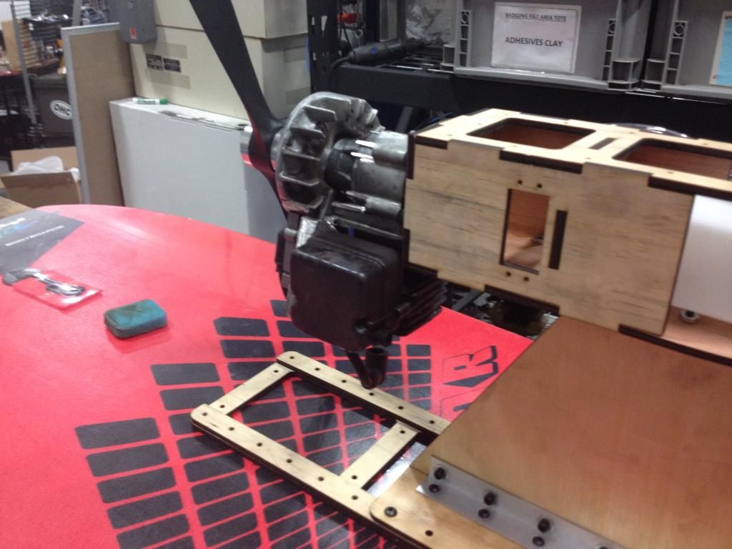
Here it is at its current state. New engine (well same model, different engine). Tightened everything up and its a fair bit stiffer now. hope to give it a run tomorrow and see how it goes. Some the linkages are rigged, and its still doesn't have the side panels or top cover on but its close.
 08-31-2014, 12:51 PM
#23
Senior Member
Join Date: Dec 2013
Posts: 432
Likes: 0
Received 0 Likes
on
0 Posts
I look forward to the outcome, I've just picked up a couple boards myself to experiment with this winter. By the way how have you attached the mount to the board, is so what type of fasteners did you use?
09-01-2014, 12:18 PM
#24
Thread Starter
Join Date: Mar 2009
Location: Zeeland, MI
Posts: 30
Likes: 0
Received 0 Likes
on
0 Posts
Well I was going to try it out today for the first time but the wind was really whipping up and even though I got it out at 7am, it was already to rough on the water. May give it a shot this afternoon on a smaller pond and not big open water.
As for the rail mount system to the board, I went ahead and tried the gorilla glue. Its safe on foam and appeared to work pretty well.
I tried to run it in the grass but it just wont move. This board is larger than the last one with more surface area and it also has a slick bottom which may actually hurt in the grass. Not sure. This engine is also smaller (21cc vs 25cc) and I increased the prop size as I felt the 14" prop I had was under propped. Maybe too many big changes but we will see once its on the water.
I think a redesign is in order anyway as there is just too much un supported weight with the engine. Didn't think that one through very well. I may try and brace this one up a bit more or just start over from scratch again.
Justin
09-02-2014, 09:05 AM
#25
Thread Starter
Join Date: Mar 2009
Location: Zeeland, MI
Posts: 30
Likes: 0
Received 0 Likes
on
0 Posts
Took it on its maiden voyage last night and it performed quite well! (in water, still a no go on grass) Anyway, I was quite pleased with its performance. Sadly this engine mount just isn't going to work. too much weight hanging off the front. I have another one in the works that I feel much better about. I don't think it looks as cool but it should be much stronger and capable of supporting the weight better. May try and cut and glue that up tonight and give it another go. I have a 28CC mac engine sitting here too that runs well. I think it may be a bit heavy but it may give me the power I need to install the bigger prop so I can run on grass. I may try and throw on the smaller 14" prop I had on the first boat on this one as well. Maybe it has more pitch.