


Skymaster F-18F
 02-11-2015, 04:54 PM
#1

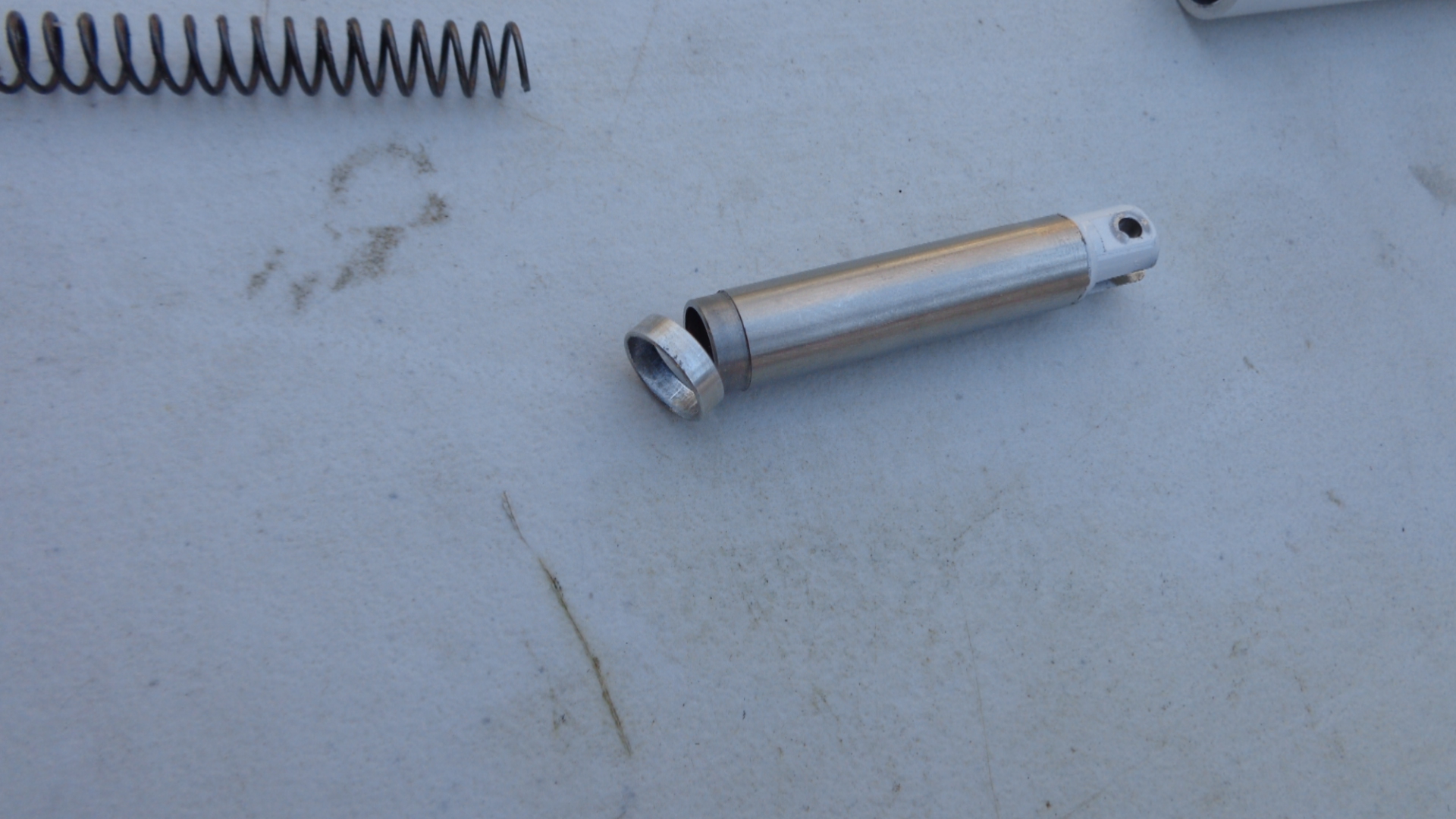
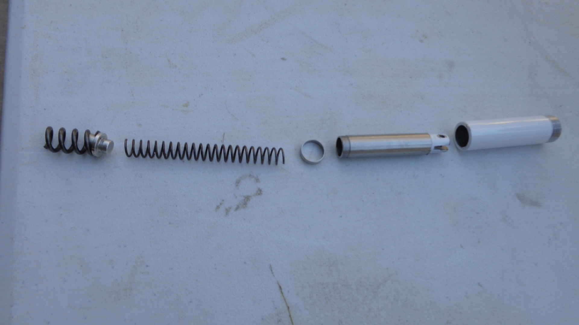
Received my Skymaster CF-18F fom Chief Aircraft the other day. All looked good until I extended the gear for the first time and the right main shock came apart and the springs came out. After examination I found that the lower shock strut has an aluminum ring at the top that is captured by the upper shock housing. This ring must be a press fit, but it is easy to slip on and off on mine. I think I have read every post about this plane before purchasing it, and I never came across a gear issue like this in any of the other builds. I don't want to send the gear back because it would take to long, so I was wondering if anyone had any experience in this area or some good advice to help me sort it out as quickly as possible.
I am extremely happy with the jet overall, there are other issues but this one has got me stumped a bit.
I would appreciate any and all help!
Luke
I am extremely happy with the jet overall, there are other issues but this one has got me stumped a bit.
I would appreciate any and all help!
Luke

 02-11-2015, 05:09 PM
#3

Join Date: Nov 2006
Location: yorba linda,
CA
Posts: 595
Likes: 0
Received 0 Likes
on
0 Posts
I've had good luck on sloppy press fits by cleaning the surfaces with alcohol after sanding them to give them a little tooth.
Then you have you choice of adhesives. CA will hold fairly well but you will still be able to disassemble it with some effort. For a more permanent bond you can use Hysol or JB Weld.
Good Luck!
Then you have you choice of adhesives. CA will hold fairly well but you will still be able to disassemble it with some effort. For a more permanent bond you can use Hysol or JB Weld.
Good Luck!
02-17-2015, 08:15 AM
#4
Thanks guys, I used the Hysol method and it appears to hold very well.
On the rest of the progress I tested the gear and gear doors, gear work great and hold air very well. On the other hand the doors did not work at all on the fuselage, I could hear air all over the place. It appears CA was used to glue the TidyStrip air hose tubing mounts in place and that hardened the air tubing and it had cracks in the tight bend areas. I replaced much of the air line and found that 3 of the air cylinders were leaking, so I replaced those. One had a melted spot on the cylinder wall it looked like, no way it was ever going to work. All of the retract system works now, I ordered 6 more air cylinders to have on hand just in case! Never read any issues like this, but I guess people just replace things like that without saying anything?
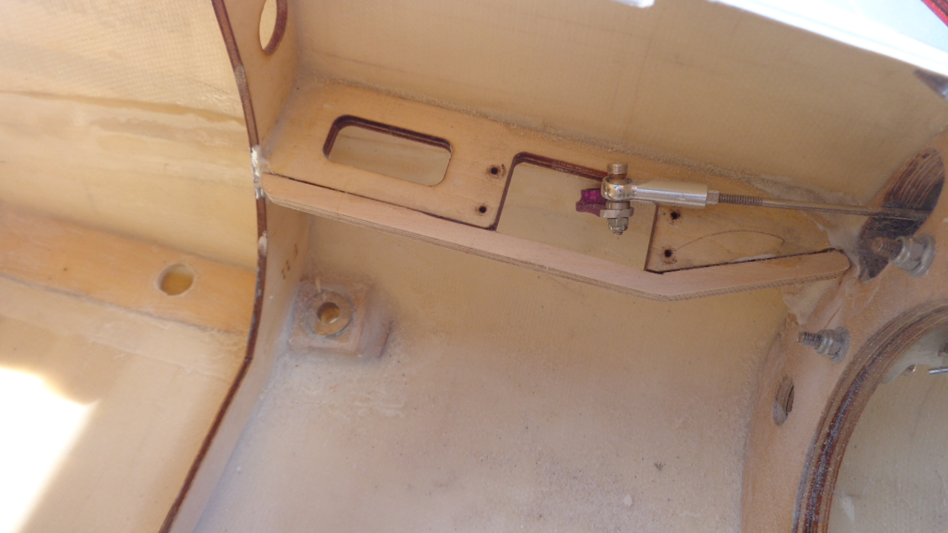
Got the elevator servo's and linkage installed, kind of a tight area, especially for my big sausage fingers but I got it done finally. Had to shorten the stabilizer shaft like everyone else, I just went with more robust linkages, those stabs are big and I wanted to do everything I could to insure and slop and trouble free installation.
I could not figure out how the control horn fit on the stab, until I realized the "No Step" decals were on the bottom of the stab!")
I'll post more of what I find as I go, it may help others down the road.
On the rest of the progress I tested the gear and gear doors, gear work great and hold air very well. On the other hand the doors did not work at all on the fuselage, I could hear air all over the place. It appears CA was used to glue the TidyStrip air hose tubing mounts in place and that hardened the air tubing and it had cracks in the tight bend areas. I replaced much of the air line and found that 3 of the air cylinders were leaking, so I replaced those. One had a melted spot on the cylinder wall it looked like, no way it was ever going to work. All of the retract system works now, I ordered 6 more air cylinders to have on hand just in case! Never read any issues like this, but I guess people just replace things like that without saying anything?
Got the elevator servo's and linkage installed, kind of a tight area, especially for my big sausage fingers but I got it done finally. Had to shorten the stabilizer shaft like everyone else, I just went with more robust linkages, those stabs are big and I wanted to do everything I could to insure and slop and trouble free installation.
I could not figure out how the control horn fit on the stab, until I realized the "No Step" decals were on the bottom of the stab!
I'll post more of what I find as I go, it may help others down the road.
02-17-2015, 10:39 AM
#6
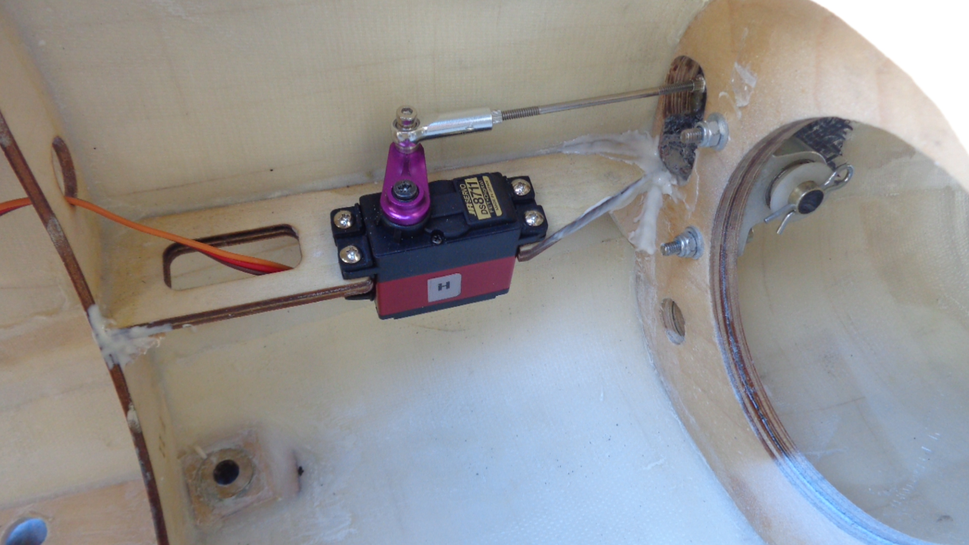
Good eye on that, I know many of these have flown stock, but when I grab that servo plate it has some flex. It is not tied into the front or back former, just glue and not sure what kind of glue, so I will add some angle blocks with Hysol on both ends. Thanks!
02-17-2015, 12:05 PM
#8
Join Date: Dec 2006
Location: harwich, UNITED KINGDOM
Posts: 709
Likes: 0
Received 0 Likes
on
0 Posts
i would use some aluminium L brackets and screw and glue them to the front and rear formers the whole set up looks weak also some triangles cut from ply under the mount also attached to the formers you need to send some of the flight stress to more than glue joints.
if you can get them out I would recut them so the servo it totally surrounded by wood it just does not look right seeing one of the sides of the servo showing.
good luck with it
if you can get them out I would recut them so the servo it totally surrounded by wood it just does not look right seeing one of the sides of the servo showing.
good luck with it
02-18-2015, 03:01 PM
#9
Hi Jeremy, cool you have a Hornet on the way, what paint scheme?
I believe the elevator servo mount is more than sufficient with some extra angle that I added. It is very easy to make things VERY strong and heavy, but it takes a craftsman to make them light and just the right amount of strength needed for the job.
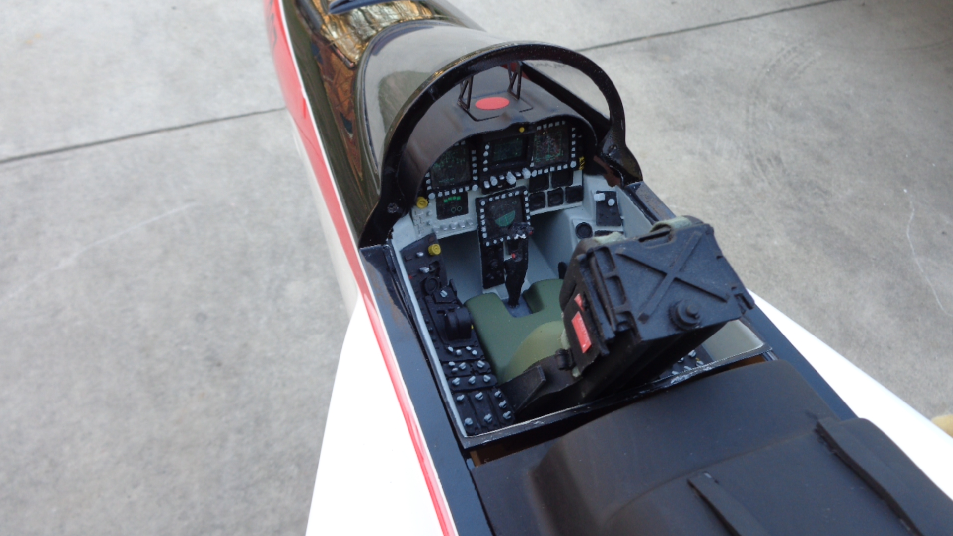
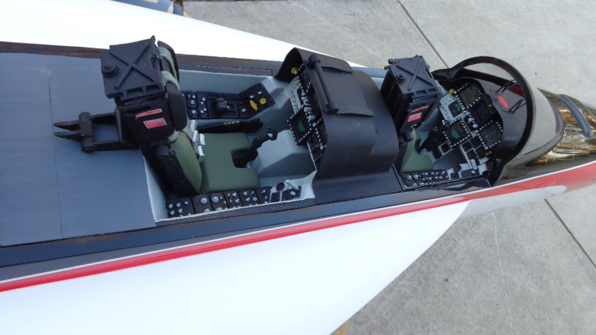
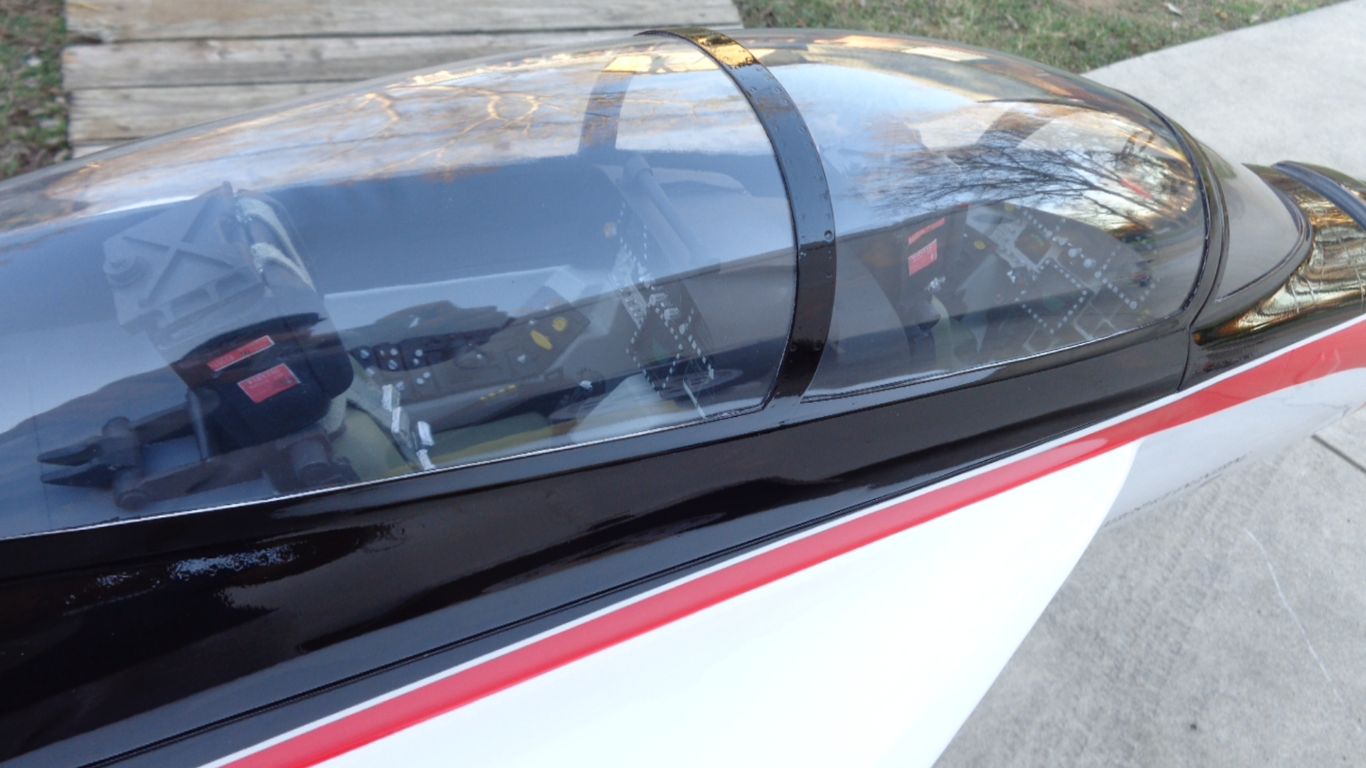
I am detailing as I go, much harder to paint the gear doors after they have already been installed, but I did it, freehand also! Same technique as pinstripers use.
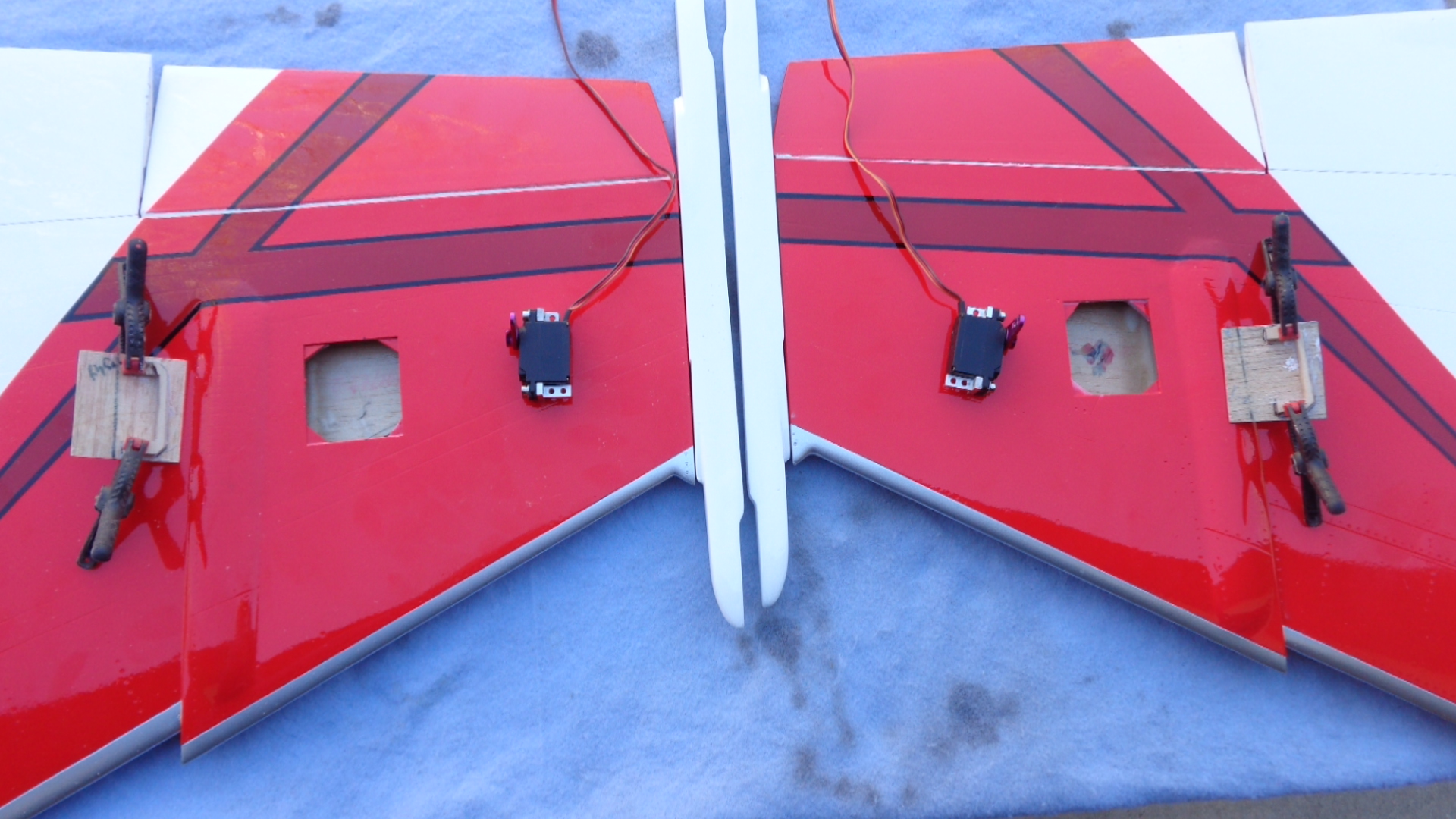
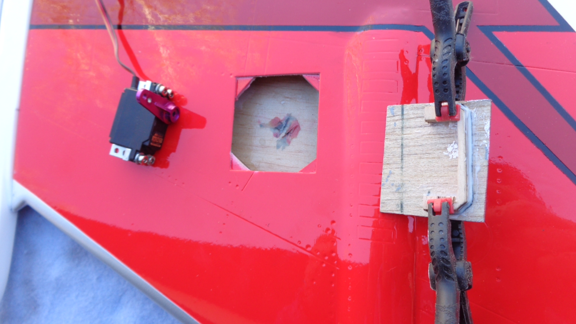
I am using JR DS3421's as recommended and was setting up the hatches when I discovered that the hatches are on different spots on the wing. You can see the line I used according to the panel line where the cover goes (I never got pushrod covers with my plane) they are off quite a bit and there is not any room to move the servo around. Even with the mini servo, space is tight.
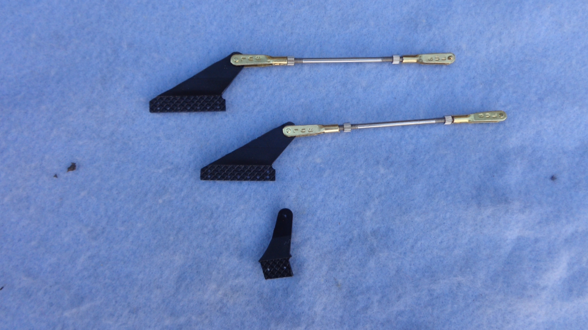
I'm using bigger control horns, the picture shows the small stock one with my replacements.
I believe the elevator servo mount is more than sufficient with some extra angle that I added. It is very easy to make things VERY strong and heavy, but it takes a craftsman to make them light and just the right amount of strength needed for the job.
I am detailing as I go, much harder to paint the gear doors after they have already been installed, but I did it, freehand also! Same technique as pinstripers use.
I am using JR DS3421's as recommended and was setting up the hatches when I discovered that the hatches are on different spots on the wing. You can see the line I used according to the panel line where the cover goes (I never got pushrod covers with my plane) they are off quite a bit and there is not any room to move the servo around. Even with the mini servo, space is tight.
I'm using bigger control horns, the picture shows the small stock one with my replacements.
02-18-2015, 03:26 PM
#10
My Feedback: (3)

Join Date: Oct 2005
Location: san jose,
CA
Posts: 880
Likes: 0
Received 0 Likes
on
0 Posts
Luke, you may want to check how close the pipe comes to those elevator rods. On the C variant it is very close and requires cutting down the excess rod to avoid heating the whole assembly.
Looks good though.
Looks good though.
02-18-2015, 03:36 PM
#11

dion, The ply they used for the stab servos isnt real ply I would add some aircraft ply to strengthen it. Its two 1/8 pieces of something, they like to use the stuff because its light but this is one area I would not have used it. They should have used the same wood as the bulkhead just aft of it. The used stuff for my turbine rails on my last project I was able to pull the two pieces apart and could have easily snapped it into. I laminated mine with carbon fiber.
 02-18-2015, 06:48 PM
#12
Thanks for the input guys, really appreciate it.
dbsonic, I have at least 1/4" clearance, the pipe is not going to exit the center of the fiberglass exhaust cones, in fact the exhaust ends of the pipe are so close together I almost have to cut into the fiberglass cone. I can cut more off of the rods, and I will do that to get as much as I can.
Keith, I can laminate the stab servo mounts with carbon fiber cloth or I could use .040 G10, do you think if I lay some carbon fiber cloth over the ply that they will be fine?
02-18-2015, 08:04 PM
#13
Yeah the carbon should do fine plus you could run it up the skin about an inch to help as well. I would still add two ply blocks to help support the servo screws. My f14 stab servo boxes needed repair plus extra blocks because even with a drilled hole the ply still split with the screws. May not be a problem but such a simple mod could prevent a possible bad day.
02-19-2015, 10:18 AM
#14
OK, I hope I have not added to much weight, here is what I have done.
I first added a cap strip of 1/4" aircraft grade ply epoxied to the original servo mount plate, this added considerable strength and I probably could have left it at that.
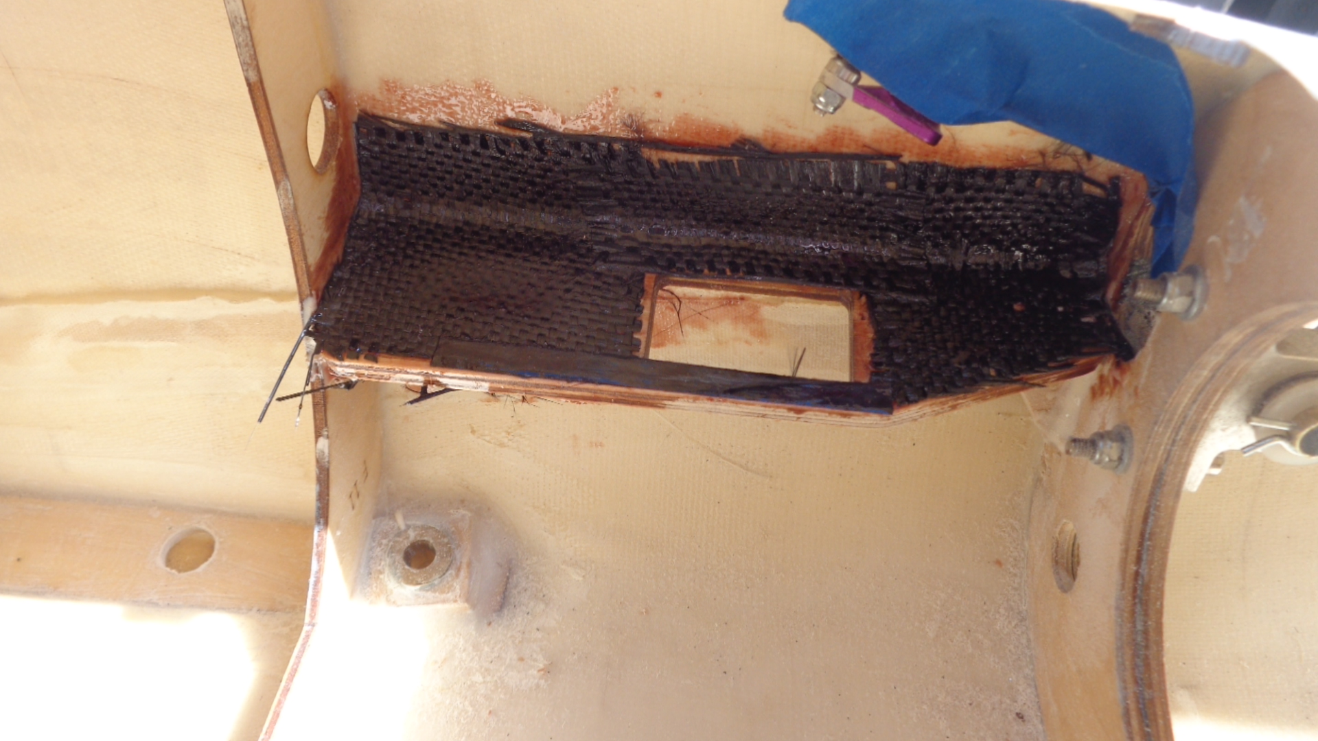
Then using West Systems epoxy I added carbon fiber cloth. One thing is for sure about my elevator set up, it has the best of everything and even if it is heavy I will never have to worry about it. It's about 70 degrees today, so it's nice to have the epoxy set up so fast!
Can we call the elevators done?
Luke
I first added a cap strip of 1/4" aircraft grade ply epoxied to the original servo mount plate, this added considerable strength and I probably could have left it at that.
Then using West Systems epoxy I added carbon fiber cloth. One thing is for sure about my elevator set up, it has the best of everything and even if it is heavy I will never have to worry about it. It's about 70 degrees today, so it's nice to have the epoxy set up so fast!
Can we call the elevators done?
Luke
02-19-2015, 12:39 PM
#15
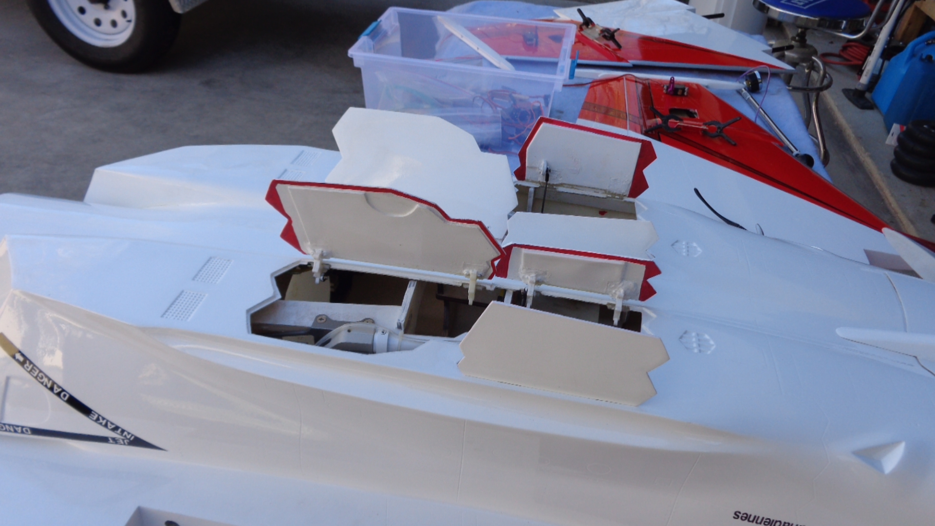
The way Skymaster avoided interference with the stab mechanism is to make the pipe nozzles very close together, in fact they are so close I had to modify the fiberglass exhaust cones. The ply ring inside of them pretty much has to be cut out and I'll have to make a new one.
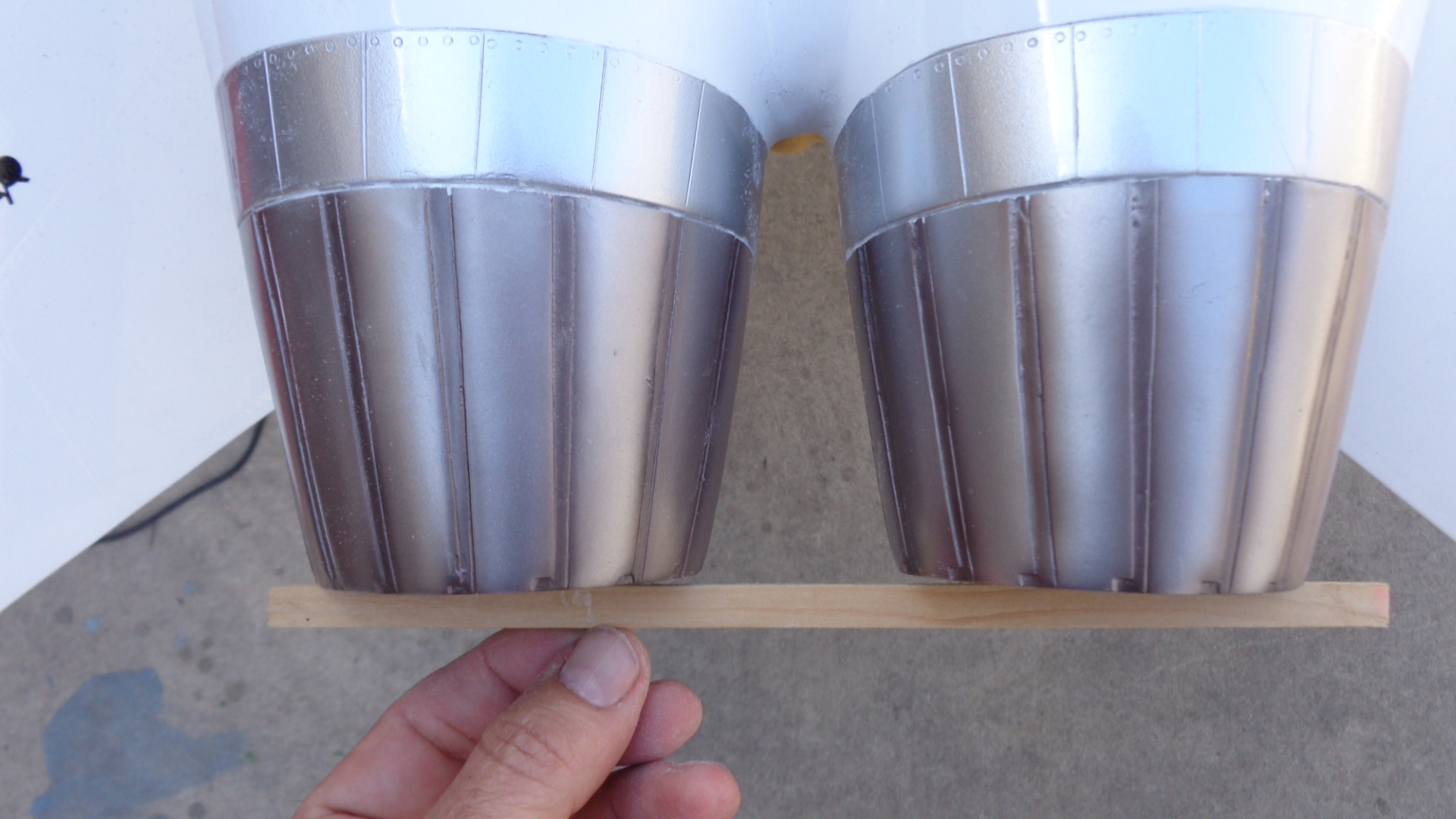
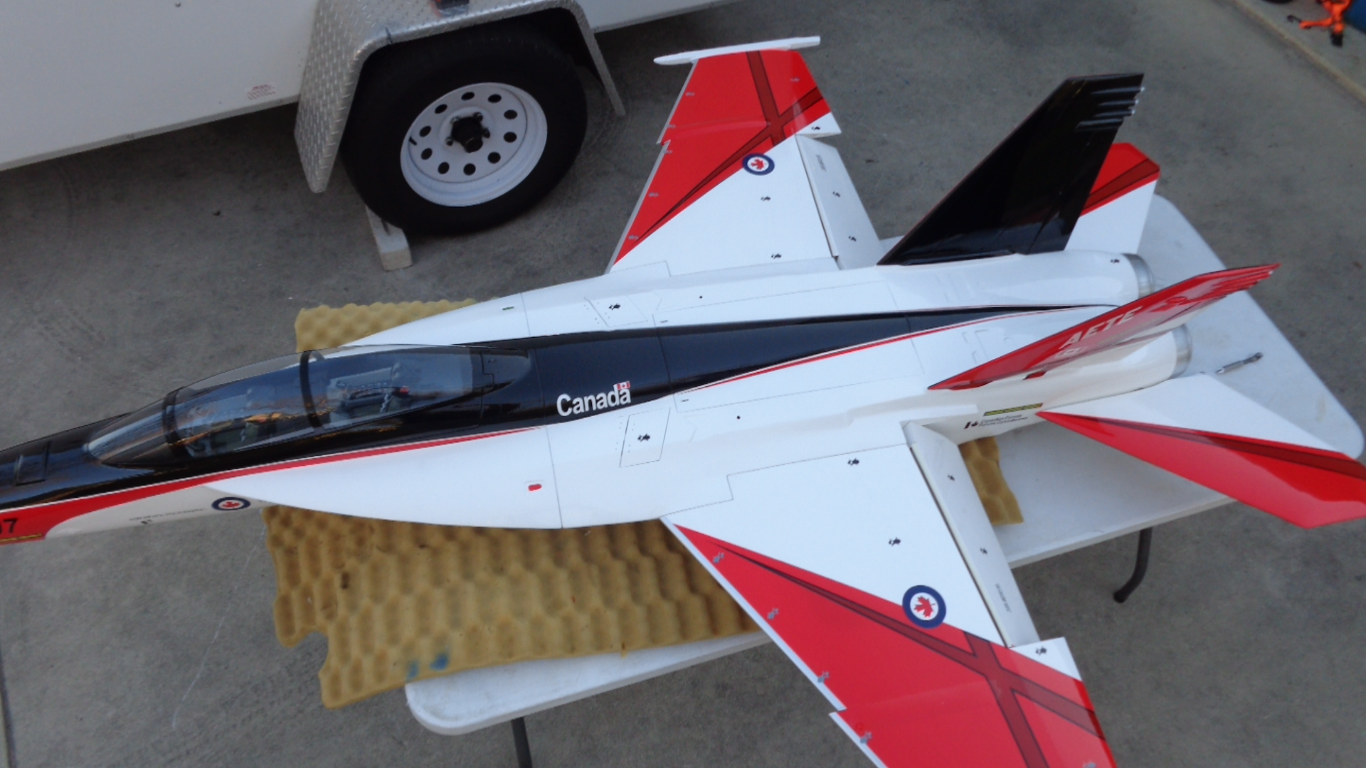
If you look from the top you can see that I had to sand about 1/4" off the fuselage side to get 1/8" at the ends. This means the fuselage part is actually angled out, so you can tell when you know what to look for, but no one will be able to tell. When I get the pipe installed I'll take a picture of how they exit the fuselage, you will see what I mean by close together.
If you look from the top you can see that I had to sand about 1/4" off the fuselage side to get 1/8" at the ends. This means the fuselage part is actually angled out, so you can tell when you know what to look for, but no one will be able to tell. When I get the pipe installed I'll take a picture of how they exit the fuselage, you will see what I mean by close together.
 02-20-2015, 10:38 AM
#20
Waiting for the Hysol to dry on the ailerons.
I'm debating the flap servo set up, Skymaster says you can hook up a linkage for installation of the flap servo inside the fuselage, but I have no idea where to get the part that goes on the servo arm, any ideas?
02-20-2015, 11:54 AM
#22
My Feedback: (3)
Join Date: Oct 2005
Location: san jose,
CA
Posts: 880
Likes: 0
Received 0 Likes
on
0 Posts
I think for flaps you got to go with install in the wing like is done for the aileron(ail linkage is already exposed). Should be deep enough pocket for a standard servo in the wing. Just got to make sure not to cut into ribs so you probably want to make a template and probe/feel out the locations of those ribs and draw on the template.
02-20-2015, 01:05 PM
#23

Glad to see another build on this model, mine is slowly coming along but other projects have been in the way, I am putting a 210 in mine with a custom Tam pipe, I have several modifications I'm doing and will put the info together and do a build thread soon!!
02-23-2015, 01:01 PM
#24

Join Date: Jan 2007
Location: Castle Rock,
CO
Posts: 267
Likes: 0
Received 0 Likes
on
0 Posts
How many channels are you going to end up using? Even with flap and rudder sharing channels, I don't think my 11CH XG11 will have enough?
THR, RAIL, LAIL, RELE, LELE, RUD, FLAP, GEAR, BRAKES, DOORS, AIRBRAKE, STEERING = 12. Plus I would like to have the rudders separate to do the airbrake mixing of both rudders inward. I will be using XBUS, so maybe there are some channels I can save there, but I don't think so.
Thoughts?
THR, RAIL, LAIL, RELE, LELE, RUD, FLAP, GEAR, BRAKES, DOORS, AIRBRAKE, STEERING = 12. Plus I would like to have the rudders separate to do the airbrake mixing of both rudders inward. I will be using XBUS, so maybe there are some channels I can save there, but I don't think so.
Thoughts?