


2.4 GHz antenna placement on plane?
 03-04-2015, 02:24 PM
#1
Senior Member
Thread Starter
My Feedback: (30)
Join Date: Feb 2002
Location: York, PA
Posts: 330
Likes: 0
Received 0 Likes
on
0 Posts
Will this be a good placement for the antenna on a 2.4 GHz system?
I routed them out the bottom of the plane, put them 90 degrees apart and taped them to the bottom of the plane.
Will this work all right?
I routed them out the bottom of the plane, put them 90 degrees apart and taped them to the bottom of the plane.
Will this work all right?
 03-04-2015, 03:58 PM
#2


Join Date: Oct 2002
Location: Lyndonville, VT
Posts: 3,305
Likes: 0
Received 0 Likes
on
0 Posts
That's a good arrangement, but it would also work just as well inside the fuselage, since it's made of balsa.
The only time you need to get them outside of the fuselage is carbon fiber is involved.
Pete
The only time you need to get them outside of the fuselage is carbon fiber is involved.
Pete
03-05-2015, 05:37 AM
#6
Actually it is not a good installation because, one antenna ought to be vertically polarized and the other horizontal. Cross polarization reduces reception strength by about one half. What your installation will do is provide superior reception some of the time and poor reception some of the time. The better installation eliminates the poor reception time by always having one antenna that is correctly polarized.
If you left one whisker sticking straight down and taped the other to the bottom of the plane... positioning would be correct. But, as others have noted, there is no need to have the antennas outside of a balsa plane. In fact, such is not helping at all. Higher frequencies like 2.4mhz are slightly attenuated by wood structures, which means that when the plane is rolling, it is exposing the antennas to no structure or double structure. The better course is to avoid weak signal issues, so exposing to one structured side of the plane all the time is better than exposing to both sides of the structure some of the time. Having said that, structure signal degradation is far less of an issue than is polarization.
If you left one whisker sticking straight down and taped the other to the bottom of the plane... positioning would be correct. But, as others have noted, there is no need to have the antennas outside of a balsa plane. In fact, such is not helping at all. Higher frequencies like 2.4mhz are slightly attenuated by wood structures, which means that when the plane is rolling, it is exposing the antennas to no structure or double structure. The better course is to avoid weak signal issues, so exposing to one structured side of the plane all the time is better than exposing to both sides of the structure some of the time. Having said that, structure signal degradation is far less of an issue than is polarization.
03-05-2015, 08:23 AM
#8
AA5BY (Amateur call sign??) has a good explanation.
This is what I usually tell guys at my field. I try to keep it simple.
Think of it this way, imagine the attitude your plane will fly in most of the time (flat and level). Antenna systems are vertically and/or horizontally polarized. So place 1 antenna flat to the floor of your plane (horizontal), and one antenna pointing to the sky (or ground, vertical), like an L. That way not matter what attitude your plane is in it should be no more than 45 degrees off. So you limit reception loss as best you can. Now if you want to be really anal, and have a system that support remote receivers, then place one of the remotes at a 45 degree angle. But most of the time that is not needed.
I'm glad I now have telemetry where I actually know the receive levels real-time. It really helps you optimize your antenna placement.
03-05-2015, 09:17 AM
#9
Member
Join Date: Feb 2014
Posts: 87
Likes: 0
Received 0 Likes
on
0 Posts
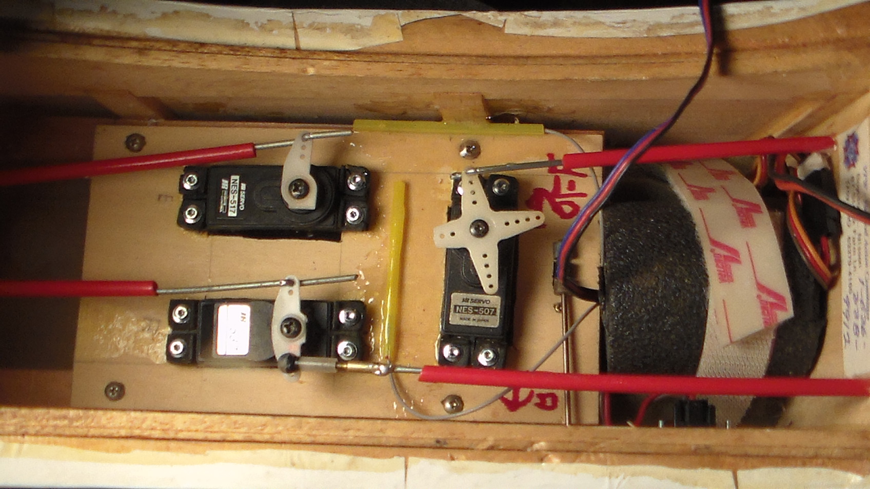
Here is a picture of the antenna placement on 1 of my low wing airplanes. This is a brand new Tactic TR625 6 channel receiver with 2 flights so far. I just got the radio last Wednesday and test flew it Monday afternoon. I had multiple problems with the motor and the nosegear on the plane so I quit flying and went home. The radio installation worked perfect. I have been using this type of antenna placement for years and have yet to experience a glitch. All my other airplanes are using Airtronics 2.4 with twin antennas.
Thanks,
Larry
Larry Kopecky
Conyers, Georgia
Thanks,
Larry
Larry Kopecky
Conyers, Georgia
03-05-2015, 10:11 AM
#10

My Feedback: (53)
Join Date: Jul 2003
Location: milwaukee, WI
Posts: 941
Likes: 0
Received 0 Likes
on
0 Posts
[QUOTE=Larry882;11996226]Here is a picture of the antenna placement on 1 of my low wing airplanes. This is a brand new Tactic TR625 6 channel receiver with 2 flights so far. I just got the radio last Wednesday and test flew it Monday afternoon. I had multiple problems with the motor and the nosegear on the plane so I quit flying and went home. The radio installation worked perfect. I have been using this type of antenna placement for years and have yet to experience a glitch. All my other airplanes are using Airtronics 2.4 with twin antennas.
Thanks,
Larry
Larry Kopecky
Larry:
The placement is fine, but the mono-philment tips should not be covered up. Also, it is not a good Idea to wrap 2.4 receivers in foam, they are heat sensitive and can get warm. Mount them with velcro on plywood backed with foam. Mount the foam to you fuse. That is how everyone I know does it. Again just my opinion.TE]
03-05-2015, 10:44 AM
#11
Member
Join Date: Feb 2014
Posts: 87
Likes: 0
Received 0 Likes
on
0 Posts
Ok Guys, the guy asked for a simple picture of a good installation. This works, it's pretty simple and straight forward.
Chris, where is your picture? You have got to have a digital camera.
I just charged the battery from Mondays flights. it took 326 milliamps. The battery took 326 milliamps to recharge. I flew 2 6 minute flights or 163 milliamps per flight. 163 divided by 6 is 27 milliamps per minute. Question, how hot could the receiver get drawing 27 milliamps per minute? I have been flying 2.4 for at least 8 years without a glitch and have always wrapped my receivers in foam.
Thanks,
Larry
03-05-2015, 11:33 AM
#12
My Feedback: (53)
Join Date: Jul 2003
Location: milwaukee, WI
Posts: 941
Likes: 0
Received 0 Likes
on
0 Posts
Ok Guys, the guy asked for a simple picture of a good installation. This works, it's pretty simple and straight forward.
Chris, where is your picture? You have got to have a digital camera.
I just charged the battery from Mondays flights. it took 326 milliamps. The battery took 326 milliamps to recharge. I flew 2 6 minute flights or 163 milliamps per flight. 163 divided by 6 is 27 milliamps per minute. Question, how hot could the receiver get drawing 27 milliamps per minute? I have been flying 2.4 for at least 8 years without a glitch and have always wrapped my receivers in foam.
Thanks,
Larry
Chris, where is your picture? You have got to have a digital camera.
I just charged the battery from Mondays flights. it took 326 milliamps. The battery took 326 milliamps to recharge. I flew 2 6 minute flights or 163 milliamps per flight. 163 divided by 6 is 27 milliamps per minute. Question, how hot could the receiver get drawing 27 milliamps per minute? I have been flying 2.4 for at least 8 years without a glitch and have always wrapped my receivers in foam.
Thanks,
Larry
It's 10 degs here. My planes big planes are in a trailer outside. I am at work. a question was asked, if you don't like my answer, that's ok. Check out a few off the professional installs in many different threads on RCU. Learn from your mistakes, I sure have. If your install works for you great! Mine works for me, take it or leave it. Here is a picture of 4 of 12 currently flying planes. Mostly gassers, all 2.4 Futaba.
2.4 interference has more to due with environment. Our club is near a large industrial park, we have 2 huge cell tower/ micro wave repeaters near by.I take all precautions to make the best signal possible. I have seen bad installations of 2.4 equipment crash a lot of planes ( mostly spektrum, only a couple of futabas). If you live and fly out away from most interference, you can get away with less then optimal equipment and installations.
Good Luck with your flying!
03-05-2015, 11:38 AM
#13
Senior Member
Thread Starter
My Feedback: (30)
Join Date: Feb 2002
Location: York, PA
Posts: 330
Likes: 0
Received 0 Likes
on
0 Posts
OK if I am understand this correct you want one vertically up the inside wall and one going horizontally across the inside floor?
Would this be a better setup?
Also is it OK to use Scotch Tape to hold the antennas in position?
Would this be a better setup?
Also is it OK to use Scotch Tape to hold the antennas in position?
 03-05-2015, 11:48 AM
#16
Senior Member
The comment that the silver tip or bare parts of the antenna coax should not be covered is not necessarily true. The only time it would be a detriment is if the covering was of a conductive nature such as a carbon tube or metal tube. If using heat shrink, insulation tubeing, etc.; it will have no detrimental effect, in fact may help as the active portion (the bare wire) will not be deformed or bent.
The following users liked this post:
FSJess (09-21-2021)
03-05-2015, 12:30 PM
#19
I use the little hollow plastic coffee stirrers to make tubes to hold the antenna tips in place. I glue the tubes to the fuse, and use a little piece of toothpick to hold the antenna in. As remarked by other, as long as the exposed part of the antenna (i.e., the last inch or so) is not
enclosed in anything that conducts, it is fine. Therefore, plastic tubes ok, brass/aluminum/CF big NO.
enclosed in anything that conducts, it is fine. Therefore, plastic tubes ok, brass/aluminum/CF big NO.
03-05-2015, 12:40 PM
#20
Join Date: Oct 2002
Location: Lyndonville, VT
Posts: 3,305
Likes: 0
Received 0 Likes
on
0 Posts
Excellent re-purposing of those coffee stirrers! Just make sure to rinse them out first!
I use a dab of that canopy glue RC 56 on the coax wire were it goes into the tubes I glue in the plane. This is the stuff that stays rubbery, and it peels right off the insulation without any damage if you need to pull the receiver out of the plane.........Y'know, like after a dumb thumbs maneuver")
Pete
I use a dab of that canopy glue RC 56 on the coax wire were it goes into the tubes I glue in the plane. This is the stuff that stays rubbery, and it peels right off the insulation without any damage if you need to pull the receiver out of the plane.........Y'know, like after a dumb thumbs maneuver
Pete
03-05-2015, 04:41 PM
#21
My Feedback: (19)
The comment that the silver tip or bare parts of the antenna coax should not be covered is not necessarily true. The only time it would be a detriment is if the covering was of a conductive nature such as a carbon tube or metal tube. If using heat shrink, insulation tubeing, etc.; it will have no detrimental effect, in fact may help as the active portion (the bare wire) will not be deformed or bent.
03-05-2015, 10:43 PM
#22
One of the reasons against covering an antenna wire has to do with moisture on the covering. Moisture is conductive and if it gets on the antenna wire... no big deal, but when it gets on a shield covering the wire, it then takes on some of the properties of a coax shield and attenuates the signal. It should be understood that if the Whiskers were fully covered by the coax shield and not exposed to a certain electrical wave length at the end of the coax, there would be no antenna.
03-05-2015, 11:35 PM
#24
Member
Join Date: Feb 2014
Posts: 87
Likes: 0
Received 0 Likes
on
0 Posts
Come on Guys. We are engineering this issue to death. Sea 157 started this thread asking for advise about twin antenna wires. When he didn't get anything he understood he asked for pictures. He didn't ask about Carbon Fiber Covering, Coffee stirirs,trailers or P51 pictures. There are several pictures showing radio installations that will all work including mine.
A little bit of Knowledge can be a dangerous thing.
Thanks,
Larry
A little bit of Knowledge can be a dangerous thing.
Thanks,
Larry
03-06-2015, 04:25 AM
#25
One of the reasons threads get over done is because of post like #9 that picture a poor installation and just because it has always worked for that poster, it should work for everybody. Other posts are then required to undo the bad information. There are four things in that picture that are contrary to the receiver installation instructions likely given by most manufacturers.
Over engineering? No.... correcting bad information... Yes.
Over engineering? No.... correcting bad information... Yes.