


Ziroli 1/6 Hellcat Build
 07-20-2015, 02:43 PM
#1

Thread Starter
Hello! Welcome to my first build thread.
This project started as a result of the following:
So, another 1/6 scale bird was in order. Iron Bay failed to answer emails and phone, and their phone wouldn't go to messaging. I had been getting good service from Iron Bay until then, even when others had been complaining. I recently spoke to a club member that said they had just gotten some parts via Iron Bay. Well, too late for me - I had made my decision several months ago.
I went with Belair Kits UK - started by scaling up a 1/8 Brian Taylor design. However, the errors induced from scaling up non-computerized drawings were too great. So, they recommended reducing the Ziroli plans and cut a short kit, at 1/6 scale. I have a canopy and cowling from another supplier of a 1/6 plan. The canopy is a close fit - can probably make it work with some heat and reshaping. The cowling shape is quite different - it's back end is very squarish, not meeting up with the teardrop shape of the Ziroli F1 firewall. Looking at various drawings I can get over the internet, I think the Ziroli F1/F2 shapes are closer to the real thing.
For the remaining wood, I ordered a 'completion' kit from National Balsa Wood Co- Balsa wood, Basswood ... for the 1/5.4 Ziroli Hellcat. Using LHS (Nankin Hobbies) for any other bits, as and when needed.
Using the Precision Eagle 4.2 engine from the Byron kit. Had some welding repair work done on the exhaust manifold by Mazza Auto Parts Waterford, MI. I replaced the carb, perhaps unnecessary, but it had taken a hit and needle valves were bent. Plus, the original was no longer in production - getting spares parts for it might become a problem - so I upgraded to a current model. Then, B.J.'s Model Engine Service straightened the crank, replaced a bearing and rings, cleaned it up and upgraded the electronic ignition. Runs great, running Pennzoil ATC. After building a test stand for the engine, I discovered that a small baffle behind the carb intake smoothes the engine's performance. That 'characteristic, periodic gurgle' was not quaint feature but a result of inadequate air intake!
Yes, that was a lot of rework and repair. Guess I like taking broken things and making the work again, and better.
Landing gear needed some work, too: I've replaced bent parts, and I'm currently waiting on Robart for a couple custom rotation struts - they needed to be a bit longer for the Ziroli 1/6 vs. the Byron 1/6.
Wing structure is built - waiting on retracts. Carbon fiber wing joiners in a 3-part wing construction (have wing bag for outer panels, and transporting fuse with the wheels attached is a welcomed feature). Using magnetic building method, from Airfield Models - Radio Control Flying Aircraft and Display ... very nice system; first time using system; won't build another plane without it!

Fuse: Still putting stringers on. Will get some pictures to post.
Some goals:
Thanks to "samparfitt"! I've been reading the ZIROLI 96" F6F HELLCAT BUILD, getting some help/tips from the words and pics, there.
This is my first build of this complexity, with such little instruction. Well, that's the intro - and enough for tonight!
This project started as a result of the following:
- My Byron Hellcat was augured in June 2014 at the hands of a fellow club pilot (an excellent pilot - we were all surprised/shocked at the event; before picture, below)
- Requirements
- Re-use the salvageable parts from the Byron (engine, landing gear, pilot (though he's in need of a head and Blue Box no longer sells the figure/parts))
- Another Hellcat (I really like this plane, its history and flight performance)
- Fit within my Jeep GC
So, another 1/6 scale bird was in order. Iron Bay failed to answer emails and phone, and their phone wouldn't go to messaging. I had been getting good service from Iron Bay until then, even when others had been complaining. I recently spoke to a club member that said they had just gotten some parts via Iron Bay. Well, too late for me - I had made my decision several months ago.
I went with Belair Kits UK - started by scaling up a 1/8 Brian Taylor design. However, the errors induced from scaling up non-computerized drawings were too great. So, they recommended reducing the Ziroli plans and cut a short kit, at 1/6 scale. I have a canopy and cowling from another supplier of a 1/6 plan. The canopy is a close fit - can probably make it work with some heat and reshaping. The cowling shape is quite different - it's back end is very squarish, not meeting up with the teardrop shape of the Ziroli F1 firewall. Looking at various drawings I can get over the internet, I think the Ziroli F1/F2 shapes are closer to the real thing.
For the remaining wood, I ordered a 'completion' kit from National Balsa Wood Co- Balsa wood, Basswood ... for the 1/5.4 Ziroli Hellcat. Using LHS (Nankin Hobbies) for any other bits, as and when needed.
Using the Precision Eagle 4.2 engine from the Byron kit. Had some welding repair work done on the exhaust manifold by Mazza Auto Parts Waterford, MI. I replaced the carb, perhaps unnecessary, but it had taken a hit and needle valves were bent. Plus, the original was no longer in production - getting spares parts for it might become a problem - so I upgraded to a current model. Then, B.J.'s Model Engine Service straightened the crank, replaced a bearing and rings, cleaned it up and upgraded the electronic ignition. Runs great, running Pennzoil ATC. After building a test stand for the engine, I discovered that a small baffle behind the carb intake smoothes the engine's performance. That 'characteristic, periodic gurgle' was not quaint feature but a result of inadequate air intake!
Yes, that was a lot of rework and repair. Guess I like taking broken things and making the work again, and better.
Landing gear needed some work, too: I've replaced bent parts, and I'm currently waiting on Robart for a couple custom rotation struts - they needed to be a bit longer for the Ziroli 1/6 vs. the Byron 1/6.
Wing structure is built - waiting on retracts. Carbon fiber wing joiners in a 3-part wing construction (have wing bag for outer panels, and transporting fuse with the wheels attached is a welcomed feature). Using magnetic building method, from Airfield Models - Radio Control Flying Aircraft and Display ... very nice system; first time using system; won't build another plane without it!
Fuse: Still putting stringers on. Will get some pictures to post.
Some goals:
- Primarily a flyer - not shooting for competition, but want it to look good, right, if not fully detailed.
- Looking at NS-Modelers detail kit for Hellcat
- Dynamic Balsa 1/6 F6F cockpit kit, sliding canopy rails (manual operation - still on fence regarding RC control)
- Redesign ailerons and outboard flaps for fabric (Solartex/Pink-It/Scale Rib Stich) covering (only inboard flaps were aluminum covered, except for bottom portion of outboard flaps if/when aircraft had rocket hard points)
- Offset aileron hinges (replicate scale feature; will help reduce adverse yaw)
- True slotted flaps (This may be outside my patience and time budget! Have seen several designs for this - at 1/6 scale, fit may just be too tight; may settle on offset Robart hinge points to simulate effect. Also, haven't seen a design that replicates Hellcat's slotted design completely - on Hellcat, flaps could be deployed at any speed - basically, at over-speed condition, flaps would be blown upwards, but still be spaced back - as speed decreased to correct deployment speed, the flaps would drop. Might have been part of the reason why when used as a dive bomber, pilots would drop the landing gear (not the flaps) - the air flow would prevent full extension, but the induced drag was sufficient to slow the plan for dive bombing purposes.)
- Functional lights
- Functional cowl flaps
- Bomb drop (need source for 1/6 scale rack/bomb)
- External fuel tank (currently outside of scope, unless I can drop it, belly landings (not desired!) may cause a lot of damage; as the belly plan is separate from the wing, can add it later)
- Looking at Nelson paints for color match and low VOC content
- Looking at Futuba S-bus for control
- Figure out a cowling solution
- Buy a Ziroli cowling, 3D scan it, reduce to needed dimensions and then 3D print a cowling?
- Cut front of my fiberglass cowling off (which has scale shape) and marry it to a built up cowling?
- Hidden cowl mounts (did this on my Byron, with success)
- Functional, scale exhaust is probably out of scope, but non-functional should be in scope.
- Flying by Summer 2016.
Thanks to "samparfitt"! I've been reading the ZIROLI 96" F6F HELLCAT BUILD, getting some help/tips from the words and pics, there.
This is my first build of this complexity, with such little instruction. Well, that's the intro - and enough for tonight!
 08-14-2015, 02:26 PM
#2
Thread Starter
- Elevators going together. Will use half-round leading edge with inset hinges, as full-scale and Byron utilized; will cover with Solartex and pinking for cloth look
- Stabilizer structure done.
- Engine box installed. Parts (side walls) in short kit were a little off and 2.5mm ply. Replaced with 3/16" - for sides, top and bottom. Front mounting surface is 3/4" ply. Most of the stringers are in. As I want to mount a 32 oz. fuel tank (was not problem in Byron), it looks like I'll have remove some material from the top of the center wing rib, to form a slight recess for the bottom of the fuel tank to set in.
- Carbon fiber reinforcement in tail section
- Tail wheel former reinforced with carbon fiber cloth/epoxy. CF cloth was from Fiber Glast - if one needs a small amount, they have "swatches" for a couple bucks and it arrives next day.
- Rebuilt Precision Eagle 4.2 humming along on my custom built test stand.
My custom Robart parts arrived, today. Had Robart build a custom version of the Byron rotation strut, adding 1" to its length. They also gave me a little bit of length in the area where the torque link mount attaches to the rotation strut - so that there is now a bit of length adjustment without having to grind the torque link limit stop. Thanks, Jason (Robart), for all your help!
08-14-2015, 11:38 PM
#3

My Feedback: (60)
Join Date: Dec 2001
Location: Litchfield Park,
AZ
Posts: 7,677
Likes: 0
Received 25 Likes
on
23 Posts
Subscribed and looking forward to progress. I have a 1/6 scale Hellcat of my own underway, although progress has stalled while I attend to other priorities. I am flying a 1/8th scale Hellcat currently and it is one of the most honest and reliable warbirds I have flown. I can imagine how much better it will be at 1/6th scale! Regarding the cowl (and canopy if you need one) you may look into the accessories offered for the Don Smith plan which, I think, is handled by Precision Cut Kits. Carry on and best of luck with it!
08-15-2015, 10:05 PM
#4
Thread Starter
Thanks for commenting, Chad. Understand other priorities. My Byron was a beautiful flyer. Others that flew it said that it was the nicest handling fighter that they had ever flown - which aligns well with statements from full-scale Hellcat pilots.
One warning - get it too slow and a turn using ailerons can induce adverse yaw - this is what took out my Byron. Its also the reason for my desire to use offset aileron hinges as a counter measure.
I did pick up a canopy and cowling from PCK - the canopy is appears to be from the same molds as Byron - I have the sliding bit left from my Byron (not much survived) and its an exact match to that from PCK. It looks like I'll be able to make it fit the reduced Ziroli with little or no modification. The cowling is a different story - it's a bit squarish on both the front and back ends, which is incorrect. The Hellcat had a squarish cowling at the front, but then tapered to a tear drop shape at the firewall. The Ziroli has this cross-section correct - the Don Smith design does not (at least not the cowling I received). Without bashing it, it doesn't come close to mating up with the firewall.
Made more progress on elevators, and learned a lesson - don't assume the plans for the left and right elevators are exact mirror images of each other! They should be, but they were not - length slightly different, rib positions slighting different. Stacking the elevators showed the errors. If starting over, I would build both elevator haves off the same side (pick one, build one elevator right side up, the other, up side down). Thankfully, most of the ribs weren't that far off, so I had little rebuilding work to do, and the rest I handled by stacking the elevators and sanding their perimeters together - so same length, width, shape. I'll be building the ailerons and flaps off one plan.


- Elevators stacked
- Sanding a flat surface - I used my sanding bar held in place with my magnetic fixtures as a guide, to ensure that my sanding block moved only in a straightline
- Elevators stacked for sanding curved sections - all nice now - same length, width, shape
- Ready for mounting to stab
One warning - get it too slow and a turn using ailerons can induce adverse yaw - this is what took out my Byron. Its also the reason for my desire to use offset aileron hinges as a counter measure.
I did pick up a canopy and cowling from PCK - the canopy is appears to be from the same molds as Byron - I have the sliding bit left from my Byron (not much survived) and its an exact match to that from PCK. It looks like I'll be able to make it fit the reduced Ziroli with little or no modification. The cowling is a different story - it's a bit squarish on both the front and back ends, which is incorrect. The Hellcat had a squarish cowling at the front, but then tapered to a tear drop shape at the firewall. The Ziroli has this cross-section correct - the Don Smith design does not (at least not the cowling I received). Without bashing it, it doesn't come close to mating up with the firewall.
Made more progress on elevators, and learned a lesson - don't assume the plans for the left and right elevators are exact mirror images of each other! They should be, but they were not - length slightly different, rib positions slighting different. Stacking the elevators showed the errors. If starting over, I would build both elevator haves off the same side (pick one, build one elevator right side up, the other, up side down). Thankfully, most of the ribs weren't that far off, so I had little rebuilding work to do, and the rest I handled by stacking the elevators and sanding their perimeters together - so same length, width, shape. I'll be building the ailerons and flaps off one plan.
- Elevators stacked
- Sanding a flat surface - I used my sanding bar held in place with my magnetic fixtures as a guide, to ensure that my sanding block moved only in a straightline
- Elevators stacked for sanding curved sections - all nice now - same length, width, shape
- Ready for mounting to stab
Last edited by DaleCS; 08-17-2015 at 11:40 AM. Reason: Inline picture error
10-02-2015, 08:59 AM
#5
Thread Starter
Main landing gear installed.
The gear came from my Byron Hellcat - rebuilt after the crash. Though the same scale, found that the Ziroli would need another inch of length on the rotating strut. Robart Mfg. made up a couple new, longer rotating struts for me. Also, obtained new torque link mounts, as the originals had been ground to center the wheels in the Byron's wheel wells.
After fitting everything, I epoxied the mounting rails in place. Then, after drilling and screwing the gear in place, I found that the strut was hitting the bottom of the wing mount sleeve. Loose, I had plenty of clearance, but tightening the gear in place with the screws took all the clearance away. When selecting wing mount tube size, I stayed with the original 1.5" diameter, but went with carbon instead of aluminum as called out on the plans. I probably could have downsized to 1" tubing, and my landing gear issue would not have happened.
Options now included: Shim under the gear; remove a patch from the sleeve where the strut was hitting; carefully remove the landing gear rails and start over.
At our recent giant scale air show, I saw several scale builds that looked great on the outside, but were a mess on the inside - far and away from my build quality, though I'm not a museum grade builder. So, I decided a shim between the landing gear and the rail, hidden from sight, was acceptable. I thought this a better solution than taking a patch out of the sleeve, which would be very visible (to other builders, only, perhaps). So, that is the result one sees in the pictures.
Gear length looks spot on - I haven't removed the rib cutouts for the wheel well, but it looks like the wheels, when retracted, will be centered in the wells with little or no grinding of the torque link mounts. Looks like Robart and I got these measurements right.
The frame for the Robart landing gear is the same size as that used in the 1/5.4 (95") Ziroli Hellcat. To fit, these had to pushed up them against the wing spar webbing. There was room to push them forward, but then the gear would have to be longer, and in the down position, they'd be farther forward than plan/scale, too. As a result of their placement, there is not enough clearance between the rear air cylinder fitting and the spar webbing to fit an airline and not have it kinked. So, I drilled a hole through the webbing, behind the fitting, large enough to slide the air line through and have it move freely as the gear operates - all good - everything is moving, locking into place when retracted and extending freely. Also, I drilled a second hole through the webbing to put the air line back into the forward section of the wing, where it will then feed through the existing rib holes back to the fuse. This loop in the wheel well will be above the wing mount sleeve - should be out of sight.
Dale
10-02-2015, 09:28 AM
#6
Thread Starter
Started sheeting the fuse. Figured it would be best to have some sheeting in place to hold the shape of the fuse, before cutting out the belly pan. Also, sheeting the bottom of the fuse with the pan in place, and then cutting it out, should result in a better flow/shape - doing the pan separate from the fuse would have to be more difficult to get the sheeting all nicely aligned.
I took an idea from another build on this site, putting peg dowels into the rear of the belly pan rib, with the idea of having bolts through the front to hold it in place - eliminating visible mounting holes in the bottom of the pan. These dowels can be seen in the third picture, here. I've left them long and not glued - if glued in place I'm not sure that the pan will come out, as the front former of the pan is smack up against the back of the firewall - will there be enough clearance for the pan to rotate out? Don't know. So, unglued. And, long enough that I can easily reach them through the cockpit to remove them. After everything is cut free, can work on shaping the dowels and opening clearances -- or change to a different method of mounting.
As I sheet the fuse, I'm seeing that I probably need to do some other things before finishing the sheeting:
- air cylinder placement: -the only clear place large enough that I can find, now, is behind the cockpit at the top of the fuse; will need method to hold it up there
- rudder pull-pull lines and servo: no choice here - servo behind cockpit with wires coming out sides of fuse; have done this several times with other tail draggers - no problem
- elevator control rods: I'm not convinced yet about putting servos in h-stab, due to amount of weight I'll have to add to the nose to offset these; however, scaled down, there's little room for both elevator control rods (I want two, one for each half) and the rudder control wires; putting the servos in the h-stab would be simplest method; still considering putting two servos, one on each side of rudder servo, behind cockpit - here routing the control rods becomes an issue.
I can't run straight rods without mounting the servos on opposites sides of the fuse - which means the control rods would cross each other and the rudder control lines - messy, at best. If put a bend in the control rods, then I need a slot in the side of the fuse for each control rod - I don't like this - had this in my Byron and as the plane flew by one could see through the fuse (Guess I could cover slot with slit felt...). Flex lines would work great, but I've not seen flex lines used on large scale aircraft - the longer the flexible rods, the greater the issues one has with flex, compression, stretch, heat, etc.
If told to make a decision now, I'd go with the servos in the h-stab.
Any better ideas?
On the Byron, the decision was easy: Don't put the servos in the h-stab - its already too heavy back there; and, with a glass fuse, there are zero space concerns.
Still need to add triangular stock bracing for motor box. Also, need to consider getting my cockpit kit and sliding canopy parts ordered.
Dale
10-02-2015, 10:19 AM
#7
Thread Starter
When not building, sometimes need to do something different:


Was in Georgia for a bit, and while there on St. Simons Island, took a ride in a 1940 Waco open cockpit biplane. Getting in, noticed the similar construction techniques as we use in RC - fuse formers, stringers, fabric. Made me a bit nervous at first, But then the engine started and it was wonderful. Buzzed the airstrip on Jekyl Island, flew along the coast looking for sharks. Holding my hand outside the cockpit, I could feel the hot exhaust racing down the side of the fuse. Had been wanting to do this for many years - waited too long, but it was awesome when I finally did it. And the landing, it was the smoothest ever - and I've done a lot of flying in small planes and commercial aircraft - this guy was good!
Also, decided to take a dive with the manta rays and whale sharks at the Georgia Aquarium. 4 whale sharks about 35-40 feet long, several manta rays, dozens of sting rays and other shark types, hundreds and hundreds of other fish. Very cool! Yes, its a big aquarium (about 100 yds x 30 yds) - the engineering to build it and keep it running is amazing. The concentration of wild life is spectacular - greater than most dives one would take in the wild. And, the probability of me diving in a wild area with whale sharks present is going down each year as I get older. So, why not? Let's do it! I did! It was a luxury dive experience - locker rooms with fresh dive suits, gear laid out for each of us on the dock, assistants helping to get the gear on and adjusted, then helping us out of the water, calm seas, hot showers immediately after the dive - the only thing missing was warm chocolate chip cookies!

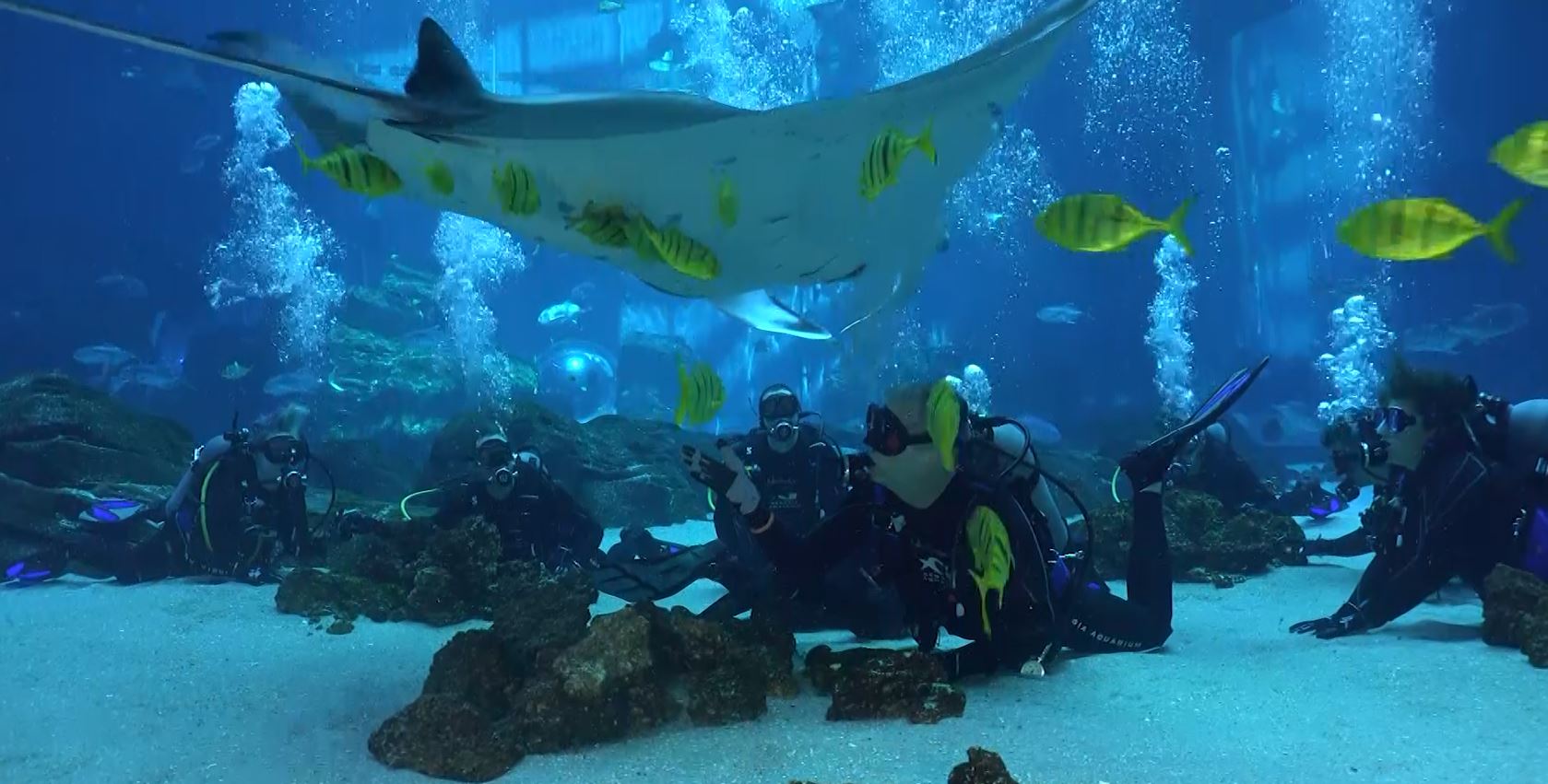
If ever in Atlanta, the Georgia Aquarium is a must see. And then off to the Atlantic Seafood restaurant on Edgewood Avenue for a great meal!
Was in Georgia for a bit, and while there on St. Simons Island, took a ride in a 1940 Waco open cockpit biplane. Getting in, noticed the similar construction techniques as we use in RC - fuse formers, stringers, fabric. Made me a bit nervous at first, But then the engine started and it was wonderful. Buzzed the airstrip on Jekyl Island, flew along the coast looking for sharks. Holding my hand outside the cockpit, I could feel the hot exhaust racing down the side of the fuse. Had been wanting to do this for many years - waited too long, but it was awesome when I finally did it. And the landing, it was the smoothest ever - and I've done a lot of flying in small planes and commercial aircraft - this guy was good!
Also, decided to take a dive with the manta rays and whale sharks at the Georgia Aquarium. 4 whale sharks about 35-40 feet long, several manta rays, dozens of sting rays and other shark types, hundreds and hundreds of other fish. Very cool! Yes, its a big aquarium (about 100 yds x 30 yds) - the engineering to build it and keep it running is amazing. The concentration of wild life is spectacular - greater than most dives one would take in the wild. And, the probability of me diving in a wild area with whale sharks present is going down each year as I get older. So, why not? Let's do it! I did! It was a luxury dive experience - locker rooms with fresh dive suits, gear laid out for each of us on the dock, assistants helping to get the gear on and adjusted, then helping us out of the water, calm seas, hot showers immediately after the dive - the only thing missing was warm chocolate chip cookies!
If ever in Atlanta, the Georgia Aquarium is a must see. And then off to the Atlantic Seafood restaurant on Edgewood Avenue for a great meal!
11-15-2015, 09:16 AM
#8
Thread Starter
More delays - will skip the details - at least some were fun/exercise related, with introduction to night mountain bike riding. 1600 lumen LED lights (handle bar and helmet mounted) light up the forest quite well!
Got the belly pan sheeted and cut out - what a pain. Thought I could control better where the glue flowed - proven wrong. I fit the half formers of the belly pan very well, which created a good area for capillary action. Made a bit of a mess sawing them apart - will use some filler to smooth it all out - primer/paint and all will be good. Wax paper between the formers prior to gluing the sheeting may have helped.
I had drilled holes for dowels in the rear of the belly pan, and for bolts in the front, so that the belly pan could be mounted without any visible mountings. Not entirely sold on this - the fit is so tight, currently, that I can't lift the belly pan without first removing the rear dowel pins. Also, not sold yet on idea of having to remove cowling in order to remove belly pan, in order to check wing hold down bolts. In the meantime, the dowels hold the pan in place for finishing purposes.
Trimmed the TE of wing ribs #1, #2 - fuselage now sits on wing! Next steps: fit and drill wing mounts.
11-17-2015, 12:44 PM
#9
Hello Dale,
if you have some question about Hellcat build, I'll be happy to help. I made two Ziroli F6F and they fly great.
Take care to put all parts as front as possible, Hellcat is short in front...
I saw that you want to use my products for scale finish, thanks in advance, check how I made "face lift" on my Ziroli Panther.
Panel lines apply on that way can reduce a lot of primer behind CG.
My first F6F was 22,5 kg and fly nice with Evolution 80.
But, second was 19,5 kg and with Zenoah GT 80 was great...
You will enjoy in this project...
On my web site you have a lot of pictures from my Hellcat buildings.
www.nsmodelers.rs
Regards from Serbia
Mirce
11-21-2015, 04:09 PM
#10
Thread Starter
Mirce,
Thank you for contacting me. I emailed you about a year ago, regarding your products for a 1/6 scale version - your reply was "Yes, we can!"
I'm still planning to use your product. I do have a question regarding control linkages for elevator servo(s) mounted behind cockpit. On my Byron, I used carbon fiber rods with 4-40 control rods at each end - the fiberglass fuse provided a cavern to work within. The scaled down Ziroli, to 1/6 (86" (2.82m) wingspan), with its fuse formers, h-stab saddle, etc., does not have much room.
Any recommendations? Pictures?
Starting to sketch in some possible routings - may have to remove some stringers to get holes drilled in formers. Definitely want this solved before sheeting remainder of fuse. Flex rods would be easy - have never used on plane this big and all advice I've ever heard or read is 'don't use flex rods.' Small planes, no problem.
For rudder and tail wheel, I'll use cable pull-pull setups, as I had on my Byron.
Thanks for following thread and any advice you can provide.
Dale
11-22-2015, 10:56 AM
#11
Thread Starter
Found this link, today - Scale Hinges: Building Secrets of the Pros
Nice setup for the elevator control - would like to have some adjustment between elevator halves in the event that I need to trim out any elevator induced roll.
Nice setup for the elevator control - would like to have some adjustment between elevator halves in the event that I need to trim out any elevator induced roll.
Last edited by DaleCS; 11-22-2015 at 11:07 AM. Reason: Fix Link
12-20-2015, 10:15 AM
#12
Thread Starter
Wing mounts cut, shaped, drilled and installed. Plans weren't clear regarding the mounting blocks for the fuse, so, decided to make them wide enough, and shaped, to fit between FWS1 and FWS2. This doubles the surface gluing area - can't be a bad thing. May also drill and dowel through the fuse sides/blocks.
Plans showed rear ply mounts glued to bottom of ribs - I decided to notch the ribs so that I can lay balsa sheet over them, easily.
Working next on wing alignment, drilling through fuse mounting blocks. Also, I want to cut out the sheeting for the tail wheel and reinstall the tail wheel - something about have the plane sitting on its wheels is motivating.
12-20-2015, 06:59 PM
#13
Thread Starter
Wing mounted/aligned, tail wheel cut-out and retract installed - my 1/6 Ziroli Hellcat stands on its own!
I used the cut-out leftover from my Byron to set the initial shape and position. The Byron Originals didn't use a Robart tail-wheel retract - it used a D&B retract, which was smaller. So, the opening I made with the cut-out was undersized, but useful. When my D&B retract developed a leak, I replaced it with a Robart and had to enlarge the opening on the Byron. So, here too, the opening I started with must be enlarged.
I disassembled the retract and installed the aluminum mounting bracket. From this, I could see how much wider I needed to make the opening at the front for the gray retract arms to pass through and attach to the aluminum bracket. With the retract mounted and air cylinder piston disconnected, I raised it (lowered, in the pics as its upside down!) to see where the wheel would hit the bottom of the fuse as the Robart #160 retract is longer than the D&B (the #160 is also for a 1/5 scale - stuffing it into a 1/6 scale is a stretch, but it worked fine on the Byron and will do fine here). I held a triangle against the back of the wheel and marked the fuse then placed another mark 1/8" further toward the tail. This last mark, is where I backed my cut-out to, marking the radius in pencil, using my Byron template. I then drew tangent lines on each side of this half circle to the front that I had widened earlier.
Straight edge and X-acto knife to cut the new sides of the wider opening, and a Dremel rotary drum to open up the radial part. Finished the retract installation by connecting the air cylinder piston, and there, it's done!
The opening does look a bit big for a 1/6 scale airplane - maybe I'll make a removable filler piece to cover the mounting bracket/bolts at the front...
Wheels down, locked in the last two pictures. Glad I only sheeted enough of the fuse to stiffen it up - its been useful to have the sides open for all this work.
01-22-2016, 04:49 PM
#14
Thread Starter
Vertical fin and rudder are framed. Added a few support details near trim tab, identified through cut-away views of full-scale aircraft.
Temporarily mounting these to fuse, I have found that the fuse has twisted - was all nicely aligned on the jig when building. Apparently there as stress in the stringers and when pulled off the jig, a nice twist became evident.
So, what to do? Well, I decided to put some torque on the tail, while applying the fuse sheeting:
In this picture, I'm showing a clamp attached to the last former, with a weight hanging off the end of the clamp. This torque is removing the twist in the fuse (the engine box has some weights on it, keeping the nose down and fuse from falling off jig). I've sheeted up enough of the fuse such that now, when I remove the clamp/weights, the twist is gone - bubbles level at stab and wing mounting surfaces!
Also in this pic, I'm showing some tracing paper - attempting to trace the outline for the balsa sheet that I'm going to apply. Trying to get cover as much as I can with bigger sheets. Nice idea. I'd say I'm 75% successful, though...still ending up with some gaps that I don't like. Filling these with wood.
Also, trying to use as little water/ammonia as possible when bending the wood into shape for glue to the fuse - some areas are great - the curves are slight enough that I don't need to wet the at all. Still as careful as I'm trying to be, some of the areas between formers/strings have gone a bit flat. "It's filler time." Ugh.
I've used epoxy and micro-balloons before, but on smaller aircraft and areas, very successfully But haven't tried on compound curved surfaces - concerned that it will just take too much time to sand and get curves right Have also used auto-body filler type products - but only on fiberglass surface. Plus, the VOC's from such products are hard on the family - its winter and I don't have ventilation to exterior. Family doesn't want to wear respirators while I'm working for some reason!
Tried Pro-Bond Elmer's wood filler once - too hard - was difficult to sand it and not take off too much surrounding wood. There's an Elmer's product recommended on one site (E849DL) but it appears the reference is either wrong or out of date - can't find this product ID anywhere. There are some other Elmer's products that might be replacements, but none are labeled 'lite' as the one reference described E849DL
One reference did catch my eye - a 50/50 mixture of Durham's Water Putty and DAP light spackling - both still readily available the big box stores. Water soluble - should answer the VOC problem. Pictures I can find seem to indicate color is very close that of balsa. Think I'll try it. If it doesn't work well, my daughter can use it for props (as in costumes, Comi-Con - not propellers - one of her patterns is getting picked up by Simplicity).
All of the references I've been able to find are 5 or more years old - so, if anyone has a better solution, product suggestion, please, let me know. Yes, I know "build it so that you don't need filler" is best - I've failed - no need to rub it in, please! Some of my fuse sheeting is beautiful - would be thrilled if all of it was turning out so.
Carbon fiber is, I've read, excellent in compression. So, I added some square carbon tube between F11 and F12. The tail wheel, when hitting the ground (landing, bumps) will apply a counter clock-wise force to F11 as shown in this pic. The carbon fiber will transfer some of this force to the fuse side, via the stringer it is glued to, and F12. The front side of F12 has a layer of carbon fiber cloth epoxied in place, too - should help keep F11 in one piece.
Next steps:
- another sheet to apply to right fuse, so that both are sheeted to the same height
- sheet the center wing section top, including balsa/ply sandwich for trailing edge
- assemble center wing section, fuse - perform another alignment check between wings, stab, fin, fuse
- order Dynamic Balsa cockpit kit
- finalize decision on elevator servo location - I can fit the control rods, but scaled down, there's won't be much meat left in F11 once the holes are drilled for the rods to pass through - I can drill smaller holes, shorten the fiberglass control rods and make the 4-40 rods attached to them longer. Ahh...servos in the stab would be so much simpler - but the balance weight penalty....others have done it this way, they're flying and having fun - I should probably worry less about this. The Hellcat was never meant to be a sailplane, after all.
01-30-2016, 03:37 PM
#15
Thread Starter
With the fuse sheeted half-way up each side and the twist removed, I went ahead and ordered several items from Dynamic Balsa: Cockpit kit, seat belt accessories, eFlight bomb release, canopy rails, 50cal 1/6 scale barrels. I'll order replica drop bombs, pilot, later - don't need them right now. Would also like to have rocket rails installed. Center tank? Not on the agenda, yet. If I do go for a center tank, I will also put a release on it. From my readings, pilots were to bring the center tanks bank, due to metal shortage - but after the fires from several hard deck crashes, they were instructed to dump them before landing. My main interest is that if I have to do a belly landing, I want the center tank gone - not getting pushed into the belly pain and/or ripping up the tail feathers.
I want to get the cockpit built and canopy rails installed, before putting any more sheeting on the fuse - seems like it will be easier to fit everything and see what is going on while the fuse is still open.
So, moved back to the center section and wings.
Created a ply/balsa sandwich for the top training edges for the flap sections:

Wing sheeting is 3/32" - so picked up some 1/16" balsa sheet and 1/32" ply. Cut each into 1" strips, cut to length and glued them together. Sample after installation in picture above.
Of course, the balsa and ply thicknesses weren't exact - but thankfully, a bit on the thick side. Some sanding was in order to get the sandwich down to 3/32" so that it would mate flush when the balsa 3/32 sheeting is applied to the wing. Took a couple 3/32" sheets and put them on either side of my ply/balsa sandwich strip, and started sanding:

The 3/32" sheets were loose, so that when my sanding block started moving them, I knew my ply/balsa sandwich was equal to that of the sheets - or at least getting close. This also helped me keep my strips a uniform thickness, end to end.

Here's a top view looking at the strip for the right, inboard flap. I have the strips installed for the both inner flaps and the right outer flap. Will get a picture, later. Currently, waiting for epoxy to set on inboard wing tubes. Once cured, will finish the TE top strip for left outboard flap.
One of the neighboring businesses to my office was conducting tests on a Merlin V-12 on Thursday. Very loud, very cool. Went and watched from the railroad tracks, where I could stand in the prop blast, about 50 yards away. I've heard these engines before, stood behind them, read WWII history, etc. But this time, I feel like I actually get a little feel for what it was like, 25,000 feet up with all that noise - it was deafening and COLD! Thoughts of being strapped to that engine for 8 or more hours, feeling that cold, gave me more respect for those pilots, even though I had given them plenty already.
50 degrees, tomorrow - Ugh! Horrible ski weather!
I want to get the cockpit built and canopy rails installed, before putting any more sheeting on the fuse - seems like it will be easier to fit everything and see what is going on while the fuse is still open.
So, moved back to the center section and wings.
Created a ply/balsa sandwich for the top training edges for the flap sections:
Wing sheeting is 3/32" - so picked up some 1/16" balsa sheet and 1/32" ply. Cut each into 1" strips, cut to length and glued them together. Sample after installation in picture above.
Of course, the balsa and ply thicknesses weren't exact - but thankfully, a bit on the thick side. Some sanding was in order to get the sandwich down to 3/32" so that it would mate flush when the balsa 3/32 sheeting is applied to the wing. Took a couple 3/32" sheets and put them on either side of my ply/balsa sandwich strip, and started sanding:
The 3/32" sheets were loose, so that when my sanding block started moving them, I knew my ply/balsa sandwich was equal to that of the sheets - or at least getting close. This also helped me keep my strips a uniform thickness, end to end.
Here's a top view looking at the strip for the right, inboard flap. I have the strips installed for the both inner flaps and the right outer flap. Will get a picture, later. Currently, waiting for epoxy to set on inboard wing tubes. Once cured, will finish the TE top strip for left outboard flap.
One of the neighboring businesses to my office was conducting tests on a Merlin V-12 on Thursday. Very loud, very cool. Went and watched from the railroad tracks, where I could stand in the prop blast, about 50 yards away. I've heard these engines before, stood behind them, read WWII history, etc. But this time, I feel like I actually get a little feel for what it was like, 25,000 feet up with all that noise - it was deafening and COLD! Thoughts of being strapped to that engine for 8 or more hours, feeling that cold, gave me more respect for those pilots, even though I had given them plenty already.
50 degrees, tomorrow - Ugh! Horrible ski weather!
02-03-2016, 08:52 PM
#16
Thread Starter
Started sheeting the top center wing section - fitting around the trailing edge sandwiches installed previously.
Found some low spots after the glue dried. Tried the 50/50 mixture of Durham's Water Putty and DAP Light Spackle.
First, found Durham's Water Putty (DWP) at Home Depot. HD also carries DAP Light Spackle (DLS), but only by the case and via ordering on-line. So, off to Lowe's.
Found that I had to add significantly more water than recommended on the DWP label - once applied to balsa, the wood really soaks the water out of the mixture fast, and the material starts to pill, making it hard to spread. So, I loaded it up with water until it would drip off the mixing stick.
This spread well, smoothly - again, the water was absorbed quickly, but enough remained in the mixture so that it spread very smoothly.
Let it dry!
Then, sand. This stuff is awesome! Sands so easily! I'm sold on it. Also, have since found other, newer posts (from 2014) where some have gone as far as 1:8 DWP to DLS. Guess I'll be doing some experimenting, varying the mixture depending on the application - filling gauges (a clamp slipped, ouch) , filling low spots in sheeting, etc.
Less than $2 for the DWP, about $7 for the DLS - nine bucks and I've got enough for several planes and projects around the house.
May try an experiment with a covering iron, heat gun - I generally don't need or use fillers when using heat shrink coverings, not since learning how to properly apply such coverings. However, I did a Great Planes Patriot 40 recently, flaring the simulated jet intake ducts into the fuse. I used epoxy/micro balloons, as I had had other fillers melt/bubble when shrinking the covering. This worked beautifully, but took a lot of sanding. If DWP/DLS stands up well to heat, it would make such projects a lot easier.
02-11-2016, 07:52 PM
#17
Thread Starter
Started sheeting the upper right wing. Edge sanded 4 4"x3/16" sheets, gluing together to form a 16" wide sheet. Marked and trimmed to fit sheet around the ply/balsa TE for the outboard flap. Shown below, I've just glued the sheet along this ply/balsa TE and clamped it flat.

Below, the right wing with upper surface sheeted.

Spent quite a bit of time figuring out how to hold the wing panel in order to build in 1.75 degrees of washout. Turned out, I need not have worried so much. After the glue setup, found that the wing panel could still be twisted a lot. Sheeting a single side did not stiffen the panel has much as I expected. So, I'll fixture the wing panel with the 1.75 degree washout in place, then epoxy the wing tube in place - this will stiffen a portion of the panel - three ribs worth.
After that, I have internal work to complete before I can complete the bottom sheeting, which will fix the washout in place.
Waiting on 50 cal barrels. Need to order offset hinges for ailerons, design/build ailerons and flaps (plans and laser cut parts are for sheet controls - I want fabric covered), make decision on servos and order, decide how complex I'm going to be with lights.
Will sheet the upper left wing, horizontal and vertical stabs.
Below, the right wing with upper surface sheeted.
Spent quite a bit of time figuring out how to hold the wing panel in order to build in 1.75 degrees of washout. Turned out, I need not have worried so much. After the glue setup, found that the wing panel could still be twisted a lot. Sheeting a single side did not stiffen the panel has much as I expected. So, I'll fixture the wing panel with the 1.75 degree washout in place, then epoxy the wing tube in place - this will stiffen a portion of the panel - three ribs worth.
After that, I have internal work to complete before I can complete the bottom sheeting, which will fix the washout in place.
Waiting on 50 cal barrels. Need to order offset hinges for ailerons, design/build ailerons and flaps (plans and laser cut parts are for sheet controls - I want fabric covered), make decision on servos and order, decide how complex I'm going to be with lights.
Will sheet the upper left wing, horizontal and vertical stabs.
02-11-2016, 10:37 PM
#18
Nice work Dale...
I think you know, but to remind, after glassing you will be in stage to work on panel lines and other details on surface.
Check this web site for that products: www.nsmodelers.rs
Regards
Mirce
I think you know, but to remind, after glassing you will be in stage to work on panel lines and other details on surface.
Check this web site for that products: www.nsmodelers.rs


Regards
Mirce
02-15-2016, 03:58 PM
#19
Thread Starter
HI Mirce,
I have not forgotten. Your detail kit is still on my 'must have' list!
I like what you did with the air canister - at 1/6 scale, I don't think I've got room to put my air canister above the engine box - will check. Also, moving the elevator and rudder/rear wheel servos up in front of the wing - nice thinking!
Are your inboard flaps controlled via a mechanical link with the outboard flaps? I see the servo, control horn on the outboard flap, but don't see how you are controlling your inboard flap. Your build thread is great - searched on your name, and "flap" and "inboard flap" - didn't find anything.
Kind regards,
Dale
Nice work Dale...
I think you know, but to remind, after glassing you will be in stage to work on panel lines and other details on surface.
Check this web site for that products: www.nsmodelers.rs
Regards
Mirce
I think you know, but to remind, after glassing you will be in stage to work on panel lines and other details on surface.
Check this web site for that products: www.nsmodelers.rs
Regards
Mirce
03-13-2016, 10:22 AM
#20
Thread Starter
I'm back - making progress, slowly. Took a week off, spending it out in Steamboat, CO. Beautiful, blue sky weather. No RC, but I did learn how to ski moguls (again - it had been 20+ years since being in the bumps) and in the trees! If I get back there in the summer, I'll have to look up the Yampa Valley Skyscrapers, just south of Steamboat.


Carbon fiber may not be new, but its not the latest technology used on this build. Here, are shown the E-flite release mechanisms and 3D printed bomb pylons from Dynamic Balsa. Apparently, I'm the first to receive these. The mounts allow the E-flite release mechs to just drop in, with easy access to the manual release and reset button.
Being 3D printed, the finish is a bit rough - but with some sanding and high build primary, they will look great. The mounting surface is flat. Therefore, I'll add a sheet of balsa to it and sand this to conform to the center wing section's bottom air foil shape. Might be able to shape the printed plastic, but sanding balsa to shape sounds easier.
Also arrived from Dynamic Balsa: Canopy kit, canopy rails, seat belt webbing/hardware and 50 cal. barrels. I may return the barrels and ask Brian to drill these out for installation of gun flash LED kit from Electrodynamics. Concerned that the equipment I have may not be well suited for drilling the bores out and just ruin them.
From Mirce's build log, saw that he had two air canisters, side by side, above the engine box. At 1/6 scale, I have room for one canister, which was sufficient for the Byron - so, I've decided to steal this idea, putting a single air canister above the engine box.
Also, Mirce has his elevator servos, one for each half, mounted next to the engine box, in front of the CG. I'm going to steal this idea also - though I need to start fitting the cockpit kit and confirm that I have room for the control rods to pass between the fuse side and cockpit walls. If this works, I'll see if I can then do the same for my rudder/tailwheel servo - it may need to be mounted behind the cockpit wall. The more working weight I can put in front of the CG, the less balance weight I should have to add. My Byron had 2 lbs of deadweight in the nose for balance. Should need less with this Ziroli design, as the built up tail surfaces feel a lot lighter than the foam/balsa sheeted Byron tail surfaces.
Next, I want to complete the V-stab sheeting and installation of my balsa/ply overhang strips for the ailerons. Then, I need to start working on servo mounting and controls, cockpit install, before finishing fuse and wing sheeting.
- H-stab top sheeting in place, working on the bottom sheeting; note the same balsa/ply laminate used for extending the sheeting rearward 1/4" past the TE spar, forming a pocket, as on the full-scale aircraft - a detail not on the plans.
- Wrapping the last of the bottom sheet to form the leading edge
- Sheeted stab, with elevators and V-stab temporarily placed on fuse
Carbon fiber may not be new, but its not the latest technology used on this build. Here, are shown the E-flite release mechanisms and 3D printed bomb pylons from Dynamic Balsa. Apparently, I'm the first to receive these. The mounts allow the E-flite release mechs to just drop in, with easy access to the manual release and reset button.
Being 3D printed, the finish is a bit rough - but with some sanding and high build primary, they will look great. The mounting surface is flat. Therefore, I'll add a sheet of balsa to it and sand this to conform to the center wing section's bottom air foil shape. Might be able to shape the printed plastic, but sanding balsa to shape sounds easier.
Also arrived from Dynamic Balsa: Canopy kit, canopy rails, seat belt webbing/hardware and 50 cal. barrels. I may return the barrels and ask Brian to drill these out for installation of gun flash LED kit from Electrodynamics. Concerned that the equipment I have may not be well suited for drilling the bores out and just ruin them.
From Mirce's build log, saw that he had two air canisters, side by side, above the engine box. At 1/6 scale, I have room for one canister, which was sufficient for the Byron - so, I've decided to steal this idea, putting a single air canister above the engine box.
Also, Mirce has his elevator servos, one for each half, mounted next to the engine box, in front of the CG. I'm going to steal this idea also - though I need to start fitting the cockpit kit and confirm that I have room for the control rods to pass between the fuse side and cockpit walls. If this works, I'll see if I can then do the same for my rudder/tailwheel servo - it may need to be mounted behind the cockpit wall. The more working weight I can put in front of the CG, the less balance weight I should have to add. My Byron had 2 lbs of deadweight in the nose for balance. Should need less with this Ziroli design, as the built up tail surfaces feel a lot lighter than the foam/balsa sheeted Byron tail surfaces.
Next, I want to complete the V-stab sheeting and installation of my balsa/ply overhang strips for the ailerons. Then, I need to start working on servo mounting and controls, cockpit install, before finishing fuse and wing sheeting.
04-02-2016, 05:57 PM
#21
Thread Starter
Ok - back again with a bit of progress, after a trip down to Atlanta and Nashville, visiting friends and family.

Both sides of the vertical stab are sheeted, with my ply/balsa laminations on the trailing edge. I've got two of three hinges in place with the leading edge of the rudder rounded.
The plans called for the leading edge of the rudder to just be a "V" shape, with flat hinges - no offset, and no overhang 'pocket' on the v-stab's trailing edge. This wasn't scale and for the amount of effort I'm putting in already, just thought it looked to much like the surface on my trainers and sport aircraft. I'd like to say I drew up the changes on a CAD program - I didn't.
Basically, I winged it. Holding up the rudder to the back of the v-stab, before rounding the leading edge of the rudder, I could see that my 'pocket' needed to be wider. So, rather than use 3/32" sheeting on the v-stab, I used 1/8" sheeting. Not much of a change, but this was enough to move the ply part of my ply/balsa laminate out to make room for the rounded rudder edge.
Using Robart hinge points with brass tube extensions:


I have a large Vise-grip with dull cutter - came this way, new - expect it can cut thick wire. However, I very gently used it to 'roll' a crimp into the brass tube. I also used epoxy to secure the hinge in the tube, but wanted that mechanical lock, not rely just on the adhesive. Two methods to secure it is better than one! The second 'hinge' picture, here, shows an assembly on top, without the crimp, and the second assembly, below, with the crimp.
Once the crimp was in, I drizzled 30 minute epoxy into the open end of the brass tube. Then, I used the back end of a drill that had the same diameter as the ID of the tube, to press the epoxy past the crimp until I saw it coming out the other end.
Need to finish the second, middle hinge installation on the rudder, then finish the tops of the rudder and v-stab. Then, repeat these steps for the elevators and h-stab.
Both sides of the vertical stab are sheeted, with my ply/balsa laminations on the trailing edge. I've got two of three hinges in place with the leading edge of the rudder rounded.
The plans called for the leading edge of the rudder to just be a "V" shape, with flat hinges - no offset, and no overhang 'pocket' on the v-stab's trailing edge. This wasn't scale and for the amount of effort I'm putting in already, just thought it looked to much like the surface on my trainers and sport aircraft. I'd like to say I drew up the changes on a CAD program - I didn't.
Basically, I winged it. Holding up the rudder to the back of the v-stab, before rounding the leading edge of the rudder, I could see that my 'pocket' needed to be wider. So, rather than use 3/32" sheeting on the v-stab, I used 1/8" sheeting. Not much of a change, but this was enough to move the ply part of my ply/balsa laminate out to make room for the rounded rudder edge.
Using Robart hinge points with brass tube extensions:
I have a large Vise-grip with dull cutter - came this way, new - expect it can cut thick wire. However, I very gently used it to 'roll' a crimp into the brass tube. I also used epoxy to secure the hinge in the tube, but wanted that mechanical lock, not rely just on the adhesive. Two methods to secure it is better than one! The second 'hinge' picture, here, shows an assembly on top, without the crimp, and the second assembly, below, with the crimp.
Once the crimp was in, I drizzled 30 minute epoxy into the open end of the brass tube. Then, I used the back end of a drill that had the same diameter as the ID of the tube, to press the epoxy past the crimp until I saw it coming out the other end.
Need to finish the second, middle hinge installation on the rudder, then finish the tops of the rudder and v-stab. Then, repeat these steps for the elevators and h-stab.
04-10-2016, 08:59 AM
#22
My Feedback: (34)
Join Date: Dec 2001
Location: Modesto,
CA
Posts: 446
Likes: 0
Received 0 Likes
on
0 Posts
Looking good Dale!
I will start my build this summer. Is anyone currently making a fiberglass fuse? I had one years ago but cannot remember where I purchased it.
Mirce, work of art Sir!
I will start my build this summer. Is anyone currently making a fiberglass fuse? I had one years ago but cannot remember where I purchased it.
Mirce, work of art Sir!
