


BJ Craft Agenda
 09-01-2015, 02:32 AM
#1
Hi Guys,
B.J. Park sent some information to me regarding the Agenda. It is his latest G2 design and is specifically for the Contra Drive. I must say, it has me thinking about trying my Contra Drive again.
Here are the details which he sent to me, I am passing them directly to you as he wrote them:
Agenda CD Specification:
Designed by BJ PARK
Manufacturing by BJ CRAFT
Wingspan 1800mm
Length 2000mm
Wing area 58.6 dm2
Stabilizer area 16.2 dm2
Spinner diameter 82-83 mm (Contra Drive)
Aileron servo on/above 6kg 2ea Servo
Elevator servo on/above 6kg 1ea Servo(Full moving)
Rudder servo on/above 8kg 1ea Servo
BJ Prototype: all SAVOX 1256TG 4ea
Net weight(ARF) 2100 g
weight 4800g-4900g
CG Wing Root from L/E 215mm (Wing bolt)
RC system 5 ch 4servo 1ESC
Difference of Agenda design from that of Essence is as following:
Conta drive prop makes a lot of turbulent swirl wash (about 2 times) than single prop does, so tail planes are in the turbulent,
yaw instability and pitch instability are larger cpmpare to single prop.
as a result arrow track straight feel is nothing (in the drift state)
The above were the result of CD installed on Essence.as G2 plane has neccessary and enough tail area, if it is converted with CD,
the performance is better than that of other planes. In my opinion the performane of converted Essence is 60% of the merits of CD.
Through Agenda I targeted to 80% of merits of CD and I designed Agenda to have at least same or better arow track straight feel than single prop.
-Datum line of fuselage is changed. vertical is higher 6cm than that of G2.
-Optimized down thrust for CD was applied.
-Nose moment was shortened 3cm : to guide turbulent swirl flow.
-the distance between main wing and canalizer was lengthened to enlarge tunnel effect.
-Height of landing gear is taller 3cm using that of Nuance. improved yaw stability.
-Rudder was reshaped to meet 2m limit with CD
-Plane form of Main wing was changed similar to elipticalshape.
-New airfoil for CD.save consumption of battery 200mah,consumption is similar with single prop.
Through the above modified design, as Agenda has both merits of G2 and CD it has the best performance.
Flight is more stable in lower speed and better arrow tack straight feel compare to single prop plane.
Best regards,
B.J. Park.
here are some more pics of the Agenda.

 09-05-2015, 02:41 AM
#6
Senior Member
Join Date: Oct 2011
Location: Stewartsville, NJ
Posts: 415
Likes: 0
Received 0 Likes
on
0 Posts
The Invitation is my new ride for 2016. Will see how that works for me. Going V4 contra is something I am thinking about for the 2018-19 season. That said, the earliest I would get into anything new for contra drive would be late 2017. Agenda will be attractive if I find the Invitation is a keeper. We'll see how others like it first. Right now, there is not much user experience or reports about BJ's G2 designs. We need more feedback and it would be nice if BJ could publish some more info on his blog. When the Nuance came out, he wrote a document about the design which gave me considerable insight into how it turned out. With all its shortcomings, I won a lot of contests with my Nuance over the past 3 years and I still have it. Will probably keep it for the scary crosswindy days when I would rather not risk wrecking the primary. Cheers!
12-08-2015, 11:05 AM
#7
Hi everyone,
Alex dropped off the Agenda this weekend and I'm getting things ready to start building.
I'll be posting a bunch of pics and weights tonight (hopefully). I unpacked it but kept things in the plastic bags so that they can acclimate to the dry humidity. I'll be opening them up and checking them over tonight.
The fuselage is primarily the same as the Essence fuselage with a different nose ring for zero side thrust and 1 degree down thrust. The wing is in a lower position than the Essence as well. B.J. told me that since July all Essence fuselages have been built with the same elimination of the chin cowl.
Here's a quick pick of the fuselage. Same great finish work as the Essence. It looks very nice.

I'll have a lot more details shortly.
Steve
Alex dropped off the Agenda this weekend and I'm getting things ready to start building.
I'll be posting a bunch of pics and weights tonight (hopefully). I unpacked it but kept things in the plastic bags so that they can acclimate to the dry humidity. I'll be opening them up and checking them over tonight.
The fuselage is primarily the same as the Essence fuselage with a different nose ring for zero side thrust and 1 degree down thrust. The wing is in a lower position than the Essence as well. B.J. told me that since July all Essence fuselages have been built with the same elimination of the chin cowl.
Here's a quick pick of the fuselage. Same great finish work as the Essence. It looks very nice.
I'll have a lot more details shortly.
Steve
 12-08-2015, 07:54 PM
#9
Hi everyone,
As promised, here are some more details.
I opened up the bags and weighed everything. In general, it is turning out to be a bit lighter than my original Essence. I also noticed that the wing and stab weights were dead even for left and right sides. Pretty impressive.
Fuse 1140
Gear wheels pants hardware 220
Right elev 70
Left elev 70
Right wing 260
Left wing 260
Channelizer 75
Rudder 85
Wing tube and hardware 70
Most items are a bit lighter, but the gear is heavier. He is using the Nuance style gear for longer length. It isn't enough weight gain to be of any concern. Overall, this is another super lightweight impressive job by B.J. The film coating is done just like the Essence with no exposed seams. Very nice work.


The wing is a little shorter than the Essence wing and is not a DTFS. It has the tapered wing tips but a more traditional root design. I laid it next to the Essence wing but the photo here is not quite the right perspective. It really isn't as small as it looks in the first pic.


The workmanship on the fuselage is very nice. I'll still be running a bead of Hysol 9462 around all the key joints, but it is laid up very nicely.


As promised, here are some more details.
I opened up the bags and weighed everything. In general, it is turning out to be a bit lighter than my original Essence. I also noticed that the wing and stab weights were dead even for left and right sides. Pretty impressive.
Fuse 1140
Gear wheels pants hardware 220
Right elev 70
Left elev 70
Right wing 260
Left wing 260
Channelizer 75
Rudder 85
Wing tube and hardware 70
Most items are a bit lighter, but the gear is heavier. He is using the Nuance style gear for longer length. It isn't enough weight gain to be of any concern. Overall, this is another super lightweight impressive job by B.J. The film coating is done just like the Essence with no exposed seams. Very nice work.
The wing is a little shorter than the Essence wing and is not a DTFS. It has the tapered wing tips but a more traditional root design. I laid it next to the Essence wing but the photo here is not quite the right perspective. It really isn't as small as it looks in the first pic.
The workmanship on the fuselage is very nice. I'll still be running a bead of Hysol 9462 around all the key joints, but it is laid up very nicely.
Last edited by shannah; 12-08-2015 at 08:10 PM.
12-08-2015, 08:05 PM
#10
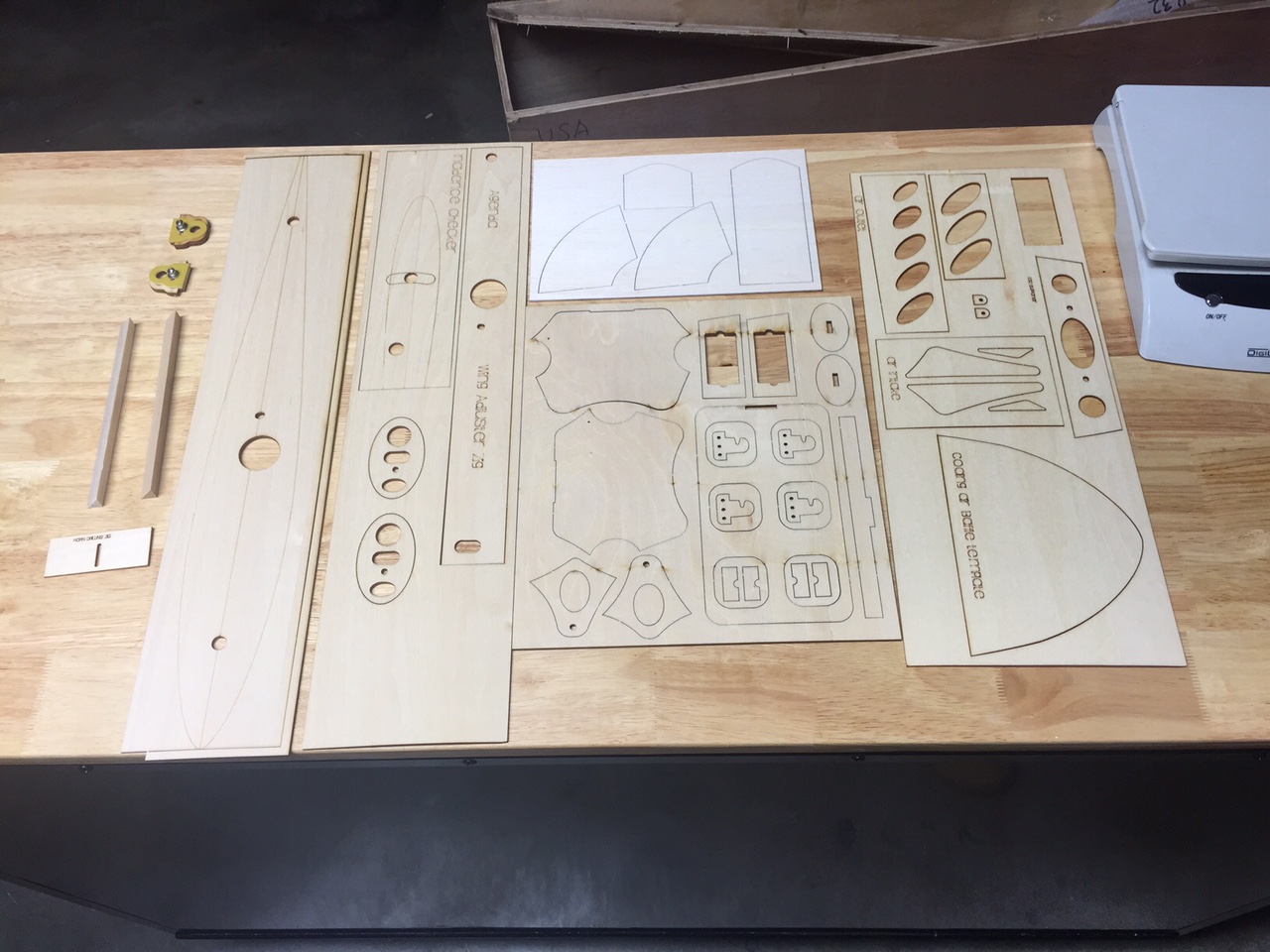
The laser cut wood parts are great. I see that he included a balsa cooling duct system. It looks good.
I also checked out the ply parts which can be used as templates for the contradrive firewall mount. I test fit my contra drive and the template lines right up. That's great news if you are using the Brenner ContraDrive.

That is tempting, however I have ordered the Adverrun drive with the Kontronik heli motor. I plan on building with that. I find it very interesting so, what the heck, I decided to give it a try. I am scratching my head a little bit about how to install it in the plane but I have a plan...
I waffled quite a bit about going back and trying a contradrive plane again. I flew a converted Visa a few years ago and never really connected with the thing so I stuck my drive in a drawer and moved on. B.J. Park has raved about this plane and contra drive combo so much that he convinced me to give it a try. I think the Adverrun belt drive system may have some advantages so it will be fun trying this. I am really looking forward to flying F17 with a system like this. The slow pace on the down lines will be a welcome benefit. Especially on that KE top hat thing...
I also checked out the ply parts which can be used as templates for the contradrive firewall mount. I test fit my contra drive and the template lines right up. That's great news if you are using the Brenner ContraDrive.
That is tempting, however I have ordered the Adverrun drive with the Kontronik heli motor. I plan on building with that. I find it very interesting so, what the heck, I decided to give it a try. I am scratching my head a little bit about how to install it in the plane but I have a plan...
I waffled quite a bit about going back and trying a contradrive plane again. I flew a converted Visa a few years ago and never really connected with the thing so I stuck my drive in a drawer and moved on. B.J. Park has raved about this plane and contra drive combo so much that he convinced me to give it a try. I think the Adverrun belt drive system may have some advantages so it will be fun trying this. I am really looking forward to flying F17 with a system like this. The slow pace on the down lines will be a welcome benefit. Especially on that KE top hat thing...
12-09-2015, 04:02 AM
#11
Senior Member
Join Date: Oct 2011
Location: Stewartsville, NJ
Posts: 415
Likes: 0
Received 0 Likes
on
0 Posts
[QUOTE=shannah;12138337].... B.J. told me that since July all Essence fuselages have been built with the same elimination of the chin cowl...
Any insight on this change? Same for new Invitations? Just weight savings or something else? Thanks for the news.
Any insight on this change? Same for new Invitations? Just weight savings or something else? Thanks for the news.
12-12-2015, 05:48 PM
#12
[QUOTE=danamania;12138648]
Hi,
I am assuming that the elimination of the chin cowl is for simplicity and weight savings. I would think that it is still there on the Invitation since it is pretty necessary for the IC engine installation etc.
Steve
I am assuming that the elimination of the chin cowl is for simplicity and weight savings. I would think that it is still there on the Invitation since it is pretty necessary for the IC engine installation etc.
Steve
12-12-2015, 06:01 PM
#13
Today I finished off the wings.
These go together just like all of his other plug-in wings. Before I got started, however, I compared the Agenda wing to the Essence wing. Here's an interesting side by side pic:

Here's a couple photos looking inside the wing. Typical lightweight construction, precision fit and nice workmanship


Putting the servos in the wings was very easy. The cutout and the servo trays were perfect and fit great


I glued the trays in by using medium CA to tack them in place then I feathered in a fillet of Baking Soda and dripped thin CA on it. I really like that method for gluing in servo mounts. Extremely strong and quick.


Installing the aileron horn is easy when using his supplied jig to guide in cutting the slot. I lined up the horn and jig with the servo pushrod and lightly traced the jig slot with a new xacto blade. Then I cut it deeper with the xacto. The grain in the balsa block under the horn slot makes it easy to cut out a nice even groove.


I used Great Planes hinges, like I always do, but the supplied hinges look like they would work fine. They were already installed and lined up nicely.
I finished it off by installing the blind nut in the supplied disk and then tightened it down to seat it.
Pretty straightforward.
These go together just like all of his other plug-in wings. Before I got started, however, I compared the Agenda wing to the Essence wing. Here's an interesting side by side pic:
Here's a couple photos looking inside the wing. Typical lightweight construction, precision fit and nice workmanship
Putting the servos in the wings was very easy. The cutout and the servo trays were perfect and fit great
I glued the trays in by using medium CA to tack them in place then I feathered in a fillet of Baking Soda and dripped thin CA on it. I really like that method for gluing in servo mounts. Extremely strong and quick.
Installing the aileron horn is easy when using his supplied jig to guide in cutting the slot. I lined up the horn and jig with the servo pushrod and lightly traced the jig slot with a new xacto blade. Then I cut it deeper with the xacto. The grain in the balsa block under the horn slot makes it easy to cut out a nice even groove.
I used Great Planes hinges, like I always do, but the supplied hinges look like they would work fine. They were already installed and lined up nicely.
I finished it off by installing the blind nut in the supplied disk and then tightened it down to seat it.
Pretty straightforward.
12-19-2015, 01:44 PM
#14
Yay!
Servos came today. This is the first time I've ordered from RC Japan. I'll do it again for sure, good savings.

I also lined up the elevators and installed the center tube in the fuselage. That was really simple, it fit nice and snug with no sanding required and was perfectly aligned. I did have to make a minor tweak to the front stab tube on the left side to lower the leading edge just slightly. I used the same method as I did on the BiSide (and also on the Agenda post by Ram). I simply took a T-Pin and poked it into the root rib around the CF tube in the left stab, all the way around the tube. This made enough clearance where I could twist the stab to align it. I dripped a small amount of CA on it to hold it in place and then final glued it. Easy to do. Everything else lined up squarely so this was an easy mounting activity.
Steve
Servos came today. This is the first time I've ordered from RC Japan. I'll do it again for sure, good savings.
I also lined up the elevators and installed the center tube in the fuselage. That was really simple, it fit nice and snug with no sanding required and was perfectly aligned. I did have to make a minor tweak to the front stab tube on the left side to lower the leading edge just slightly. I used the same method as I did on the BiSide (and also on the Agenda post by Ram). I simply took a T-Pin and poked it into the root rib around the CF tube in the left stab, all the way around the tube. This made enough clearance where I could twist the stab to align it. I dripped a small amount of CA on it to hold it in place and then final glued it. Easy to do. Everything else lined up squarely so this was an easy mounting activity.
Steve
12-24-2015, 10:27 AM
#15
I began the landing gear installation and at first I was a little puzzled as to how it was supposed to go together. The gear are mounted similar to the Nuance and Episode, however B.J. included a plywood plate for the blind nuts to be attached to. But, when I tried to fit it I saw that it seemed the plate was too long.

I contacted B.J. and he sent this string of installation pics.

The landing gear is installed with the ply nut plates, the bolts and washers as pictured here

First, you set the blind nut into the plate and line it up with the inner bolt and tighten it down until the nut just starts to seat into the ply nut plate

Then, do the same thing with the outer bolt. Use the two shorter bolts (the gear is mounted with a short and a long bolt). The long bolt has a shoulder that will prevent you from tightening down the nut plate during its installation to the gear. Final mounting in the plane will use the short and the long bolt

Next, tighten the bolts and when there is just a slight gap add some CA around the nuts and under the plate

Now you just tighten the bolts down and pull the plate tight. This is the part that I wasn't sure if it would be OK, but it pulled in great, conformed to the gear curve and the nut aligned with the bolt just fine. Pretty slick actually.

here's a couple pics of my install


Along with the gear installation pics, B.J. sent me a link to some build pics which he has just compiled. It is primarily for the Essence but the steps are identical with the Agenda since the fuse and construction are the same. These are a great help:
http://www.rcone.kr/board/index.html?id=bjair1&no=145
I will use and refer to these as I go along. I can add some tips etc. for explanation.
I contacted B.J. and he sent this string of installation pics.
The landing gear is installed with the ply nut plates, the bolts and washers as pictured here
First, you set the blind nut into the plate and line it up with the inner bolt and tighten it down until the nut just starts to seat into the ply nut plate
Then, do the same thing with the outer bolt. Use the two shorter bolts (the gear is mounted with a short and a long bolt). The long bolt has a shoulder that will prevent you from tightening down the nut plate during its installation to the gear. Final mounting in the plane will use the short and the long bolt
Next, tighten the bolts and when there is just a slight gap add some CA around the nuts and under the plate
Now you just tighten the bolts down and pull the plate tight. This is the part that I wasn't sure if it would be OK, but it pulled in great, conformed to the gear curve and the nut aligned with the bolt just fine. Pretty slick actually.
here's a couple pics of my install
Along with the gear installation pics, B.J. sent me a link to some build pics which he has just compiled. It is primarily for the Essence but the steps are identical with the Agenda since the fuse and construction are the same. These are a great help:
http://www.rcone.kr/board/index.html?id=bjair1&no=145
I will use and refer to these as I go along. I can add some tips etc. for explanation.
12-24-2015, 12:18 PM
#16
Fitting the stabs, I put the felt on prior to drilling the bolt holes in the tubes so that the spacing will be OK
I traced it out and cut it then, since this batch didn't have adhesive on it already, I dusted with a light coating of 3M77 to hold it to the root of the stab.
This time I used white felt instead of black, just to see how it looks. I like it better than the black I had been using on the Essence and BiSides
12-24-2015, 04:09 PM
#17
When installing the stab control horn, make sure that you don't insert it too deep and block the tube from the fuselage.
DON'T BLOCK THE HOLE:

I put mine in so that the linkage hole is 47mm from the surface of the stab. B.J.'s build pics show 50mm, but at 47 it is as deep as it can go and is lined up with the internal wood structure. I also installed my Essence at 47mm.


DON'T BLOCK THE HOLE:
I put mine in so that the linkage hole is 47mm from the surface of the stab. B.J.'s build pics show 50mm, but at 47 it is as deep as it can go and is lined up with the internal wood structure. I also installed my Essence at 47mm.
12-26-2015, 05:13 PM
#19
I finished off the rudder installation. The servo installation in the servo bay in the tail was very easy by using the supplied mounts.
The only thing I thought would be interesting to folks was the method I used to line up the rudder for hinging. This has always been a little tricky for me with other BJ Craft planes. He hinges all the other surface but does not hinge the rudder. I always found it a little challenging to get the rudder perfectly centered because sometimes the taper on the LE of the rudder is not exactly the same from one side to the other.
What I did was to set the rudder in place and tape it to hold it in the center.
Next, I laid my Xacto knife on the beveled LE and made a mark where the LE touches the rudder post

That made it really simple to get the rudder centered. Maybe others have been doing something similar or easier but I have struggled a bit with this step in the past and I thought I would pass this along in case anyone else was having a bit of trouble lining up the rudder.
It came out great.
Steve
The only thing I thought would be interesting to folks was the method I used to line up the rudder for hinging. This has always been a little tricky for me with other BJ Craft planes. He hinges all the other surface but does not hinge the rudder. I always found it a little challenging to get the rudder perfectly centered because sometimes the taper on the LE of the rudder is not exactly the same from one side to the other.
What I did was to set the rudder in place and tape it to hold it in the center.
Next, I laid my Xacto knife on the beveled LE and made a mark where the LE touches the rudder post
That made it really simple to get the rudder centered. Maybe others have been doing something similar or easier but I have struggled a bit with this step in the past and I thought I would pass this along in case anyone else was having a bit of trouble lining up the rudder.
It came out great.
Steve
01-01-2016, 09:54 AM
#20
Happy New Year Everyone!
I am setting up to install the wing adjusters. The first thing I did was to set the plane in my cradle and adjust the angle so that the fuse was level and the nose ring was set at the factory recommended -1 down thrust.

Next, with the fuse in the same position (-1 degree down measured on the nose ring) I put the stab incidence template on and marked the zero degree point. B.J. says to set it up for zero stab incidence.


Next I set the wing incidence template on the fuse and installed the front anti rotation pin to hold it in place. Note that the template has the root rib outlined on one side and the other side is blank. As you can see in the pic below, the blank side is showing when you put it on the left wing location. B.J. says to set the wing at +1 degree.


Mine worked out perfectly so I don't need to do much other than center the incidence adjuster in the rear when I mount it.
I did the same thing on the right. It was also lined up just right.

So, to summarize:
Thrust: -1 degree down, zero l/r
Wing: +1
Stab: 0
As for the canalyzer, B.J. says it has very little effect and it can be set anywhere between -2 and +2. I haven't checked mine yet but if it is anywhere in that range I won't bother with making any adjustments.
I am setting up to install the wing adjusters. The first thing I did was to set the plane in my cradle and adjust the angle so that the fuse was level and the nose ring was set at the factory recommended -1 down thrust.
Next, with the fuse in the same position (-1 degree down measured on the nose ring) I put the stab incidence template on and marked the zero degree point. B.J. says to set it up for zero stab incidence.
Next I set the wing incidence template on the fuse and installed the front anti rotation pin to hold it in place. Note that the template has the root rib outlined on one side and the other side is blank. As you can see in the pic below, the blank side is showing when you put it on the left wing location. B.J. says to set the wing at +1 degree.
Mine worked out perfectly so I don't need to do much other than center the incidence adjuster in the rear when I mount it.
I did the same thing on the right. It was also lined up just right.
So, to summarize:
Thrust: -1 degree down, zero l/r
Wing: +1
Stab: 0
As for the canalyzer, B.J. says it has very little effect and it can be set anywhere between -2 and +2. I haven't checked mine yet but if it is anywhere in that range I won't bother with making any adjustments.
01-16-2016, 05:46 PM
#21
I got back from my trip to China yesterday and my Adverrun drive had arrived!
It really looks nice. Great craftsmanship.


I don't want to turn this into an Adverrun drive thread, so I'll post more pictures on another thread.
Instead, I will focus on the installation of the drive into the Agenda.
First, I made a template using QCAD (an easy to use, cheap CAD program).
It is just a disk with an outer diameter of 83mm, it has a 43mm bolt circle with 4 4mm bolts, and the thrust washer clearance hole is 32mm.
I wanted to insert the PDF template here, but I can't figure out how to insert a PDF in this editor. If anyone wants one, send me a message and I'll email it.
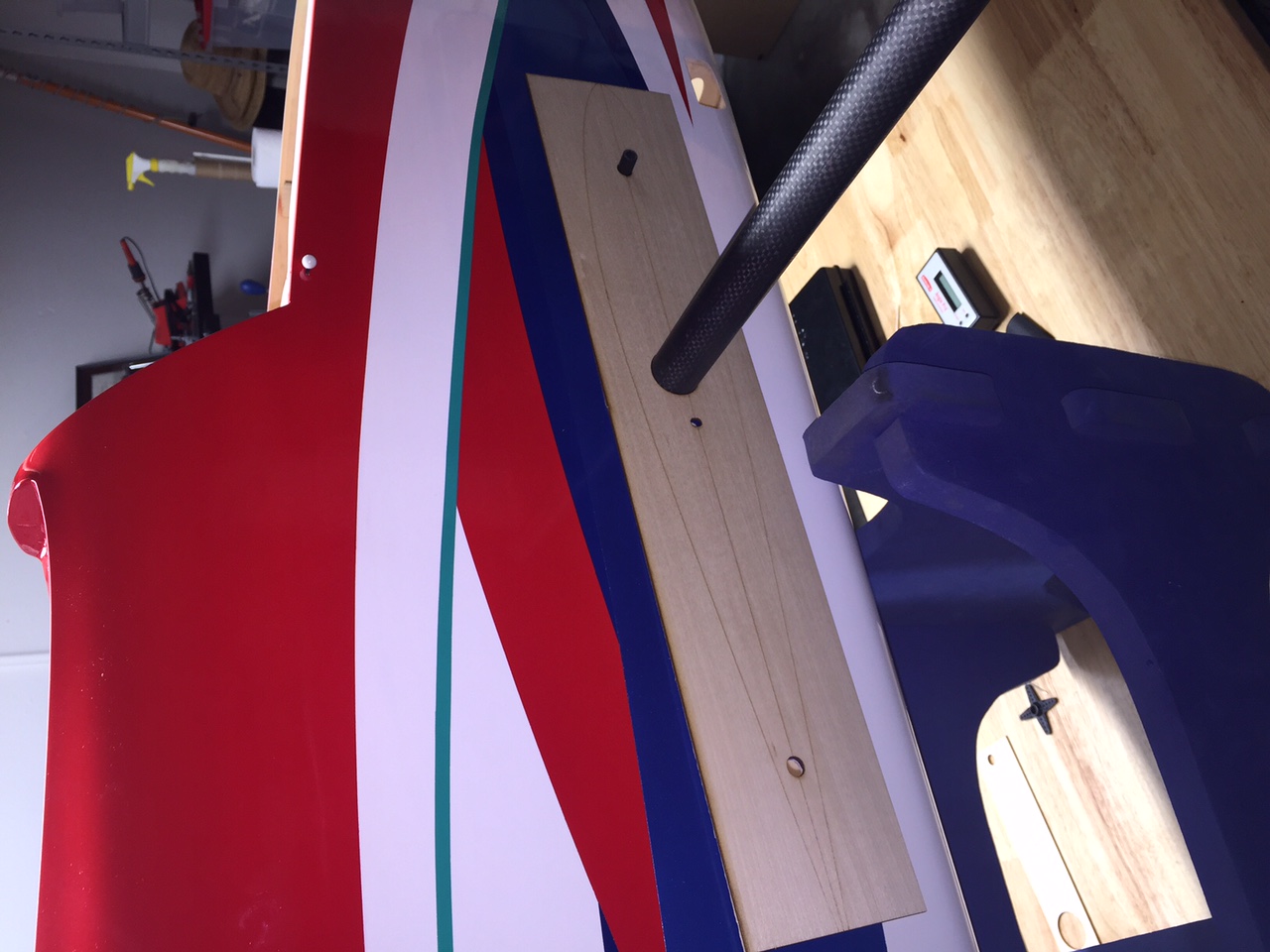
Next, I made a plywood template just to test fit it. It lined up pretty well.
Then, I decided to use Hobby King 2mm Carbon Fiber Plate for the firewall material. I transferred the outline onto the plate (I covered it in tape on both sides first.

I first drilled out the mounting bolt holes. Then, I cut it out using a Dremel. I used the Dremel drill press setup and cut it with a 1/8" grout removal bit. I then cleaned it up with a rough sanding block and it looked pretty good.

I was worried that I would have to sand the nose of the Agenda in order to get enough clearance to mount the drive unit. There is only 8mm clearance from the face of the built in vibration isolators to the face of the thrust drive washer. But, I mounted the firewall and motor and was happy to see that there was a bit over 1.5mm clearance. I tacked it in place with some drops of CA so I can pop it out if necessary but I think it is lined up OK. So, it looks like I will be able to just glue it in and be done with it. When the rear mount is secured, it won't wiggle around and should be fine.


I plan on running the 22x18 front and 22x20 rear prop setup as recommended by the Adverrun guys. B.J. also likes that prop combination.
I'll check things over closely and if it looks good then I'll glue the firewall in place with Loctite 9462.
It really looks nice. Great craftsmanship.
I don't want to turn this into an Adverrun drive thread, so I'll post more pictures on another thread.
Instead, I will focus on the installation of the drive into the Agenda.
First, I made a template using QCAD (an easy to use, cheap CAD program).
It is just a disk with an outer diameter of 83mm, it has a 43mm bolt circle with 4 4mm bolts, and the thrust washer clearance hole is 32mm.
I wanted to insert the PDF template here, but I can't figure out how to insert a PDF in this editor. If anyone wants one, send me a message and I'll email it.
Next, I made a plywood template just to test fit it. It lined up pretty well.
Then, I decided to use Hobby King 2mm Carbon Fiber Plate for the firewall material. I transferred the outline onto the plate (I covered it in tape on both sides first.
I first drilled out the mounting bolt holes. Then, I cut it out using a Dremel. I used the Dremel drill press setup and cut it with a 1/8" grout removal bit. I then cleaned it up with a rough sanding block and it looked pretty good.
I was worried that I would have to sand the nose of the Agenda in order to get enough clearance to mount the drive unit. There is only 8mm clearance from the face of the built in vibration isolators to the face of the thrust drive washer. But, I mounted the firewall and motor and was happy to see that there was a bit over 1.5mm clearance. I tacked it in place with some drops of CA so I can pop it out if necessary but I think it is lined up OK. So, it looks like I will be able to just glue it in and be done with it. When the rear mount is secured, it won't wiggle around and should be fine.
I plan on running the 22x18 front and 22x20 rear prop setup as recommended by the Adverrun guys. B.J. also likes that prop combination.
I'll check things over closely and if it looks good then I'll glue the firewall in place with Loctite 9462.
01-24-2016, 11:36 AM
#22

My Feedback: (11)
Join Date: Apr 2002
Location: Smithfield, VA
Posts: 1,056
Likes: 0
Received 0 Likes
on
0 Posts
When installing the stab control horn, make sure that you don't insert it too deep and block the tube from the fuselage.
DON'T BLOCK THE HOLE:
I put mine in so that the linkage hole is 47mm from the surface of the stab. B.J.'s build pics show 50mm, but at 47 it is as deep as it can go and is lined up with the internal wood structure. I also installed my Essence at 47mm.
DON'T BLOCK THE HOLE:
I put mine in so that the linkage hole is 47mm from the surface of the stab. B.J.'s build pics show 50mm, but at 47 it is as deep as it can go and is lined up with the internal wood structure. I also installed my Essence at 47mm.
Tony
01-24-2016, 06:32 PM
#24
I finished the installation of the Adverrun unit. I made my rear mount supports and put them in place with Loctite 9462.

I then went on to mount the rear prop, cut the spinner, mount the front prop and cut the front spinner. All in all, it was a bit of work and took me a little longer than I had planned but it came out great.


So, now I have the long list of all the little minor things to finish up. All the primary construction is done. I'm hoping to get it airborne next weekend, however my work schedule this week doesn't leave me any time. I'll let you know how things go and the final weights before flying. Right now, it is looking to be on track for another light BJ Craft plane. I ordered a set of PowerUnlimited 6000mah packs because I anticipate coming well under the weight limit so some extra capacity would be great.
Steve
I then went on to mount the rear prop, cut the spinner, mount the front prop and cut the front spinner. All in all, it was a bit of work and took me a little longer than I had planned but it came out great.
So, now I have the long list of all the little minor things to finish up. All the primary construction is done. I'm hoping to get it airborne next weekend, however my work schedule this week doesn't leave me any time. I'll let you know how things go and the final weights before flying. Right now, it is looking to be on track for another light BJ Craft plane. I ordered a set of PowerUnlimited 6000mah packs because I anticipate coming well under the weight limit so some extra capacity would be great.
Steve
01-31-2016, 05:18 PM
#25
I cut the ventilation holes and used the method B.J. recommended. I had always disliked this in the past, but by following his directions it was pretty quick and easy and it came out great.
First, you tape the tape the template in place. Then, I used a dremel engraving bit to cut. I followed the outline and it cut very quickly and accurate.

I did the same thing on the chin intake holes and also on the belly. For the chin intake, I took his template which has two cutouts and I sliced off one. It was much easier to tape the single cutout in place.


After this, I did a quick CG check so I could place my battery tray. It goes pretty far back to be at the recommended 215mm location. I decided to make my own tray so I could have a little more room to slide the packs forward or aft as needed.
I'll take pics of that when I finish the installation of the tray and receiver mounting plate.
The good news is that my weight is looking great. My loaded check for CG location which included everything shows that the weight is 4845g. This was with the F3A Unlimited 5100mah packs. That gives me plenty of margin to run my 6000mah packs. The 5100 mah packs weigh 1220g with bullet connectors, heat shrink tubing and velcro added. The 6000mah packs weigh 1295g without any connectors or velcro. So, it will easily make the weight limit with those larger packs. I don't know if I'll need them, but this gives me the option to run unlimited power on the F17 sequence.
It was raining here today so I didn't need to rush through. I'll get it done this week and have the first flight next weekend (or maybe before if I decide to skip out of work one afternoon )
)
First, you tape the tape the template in place. Then, I used a dremel engraving bit to cut. I followed the outline and it cut very quickly and accurate.
I did the same thing on the chin intake holes and also on the belly. For the chin intake, I took his template which has two cutouts and I sliced off one. It was much easier to tape the single cutout in place.
After this, I did a quick CG check so I could place my battery tray. It goes pretty far back to be at the recommended 215mm location. I decided to make my own tray so I could have a little more room to slide the packs forward or aft as needed.
I'll take pics of that when I finish the installation of the tray and receiver mounting plate.
The good news is that my weight is looking great. My loaded check for CG location which included everything shows that the weight is 4845g. This was with the F3A Unlimited 5100mah packs. That gives me plenty of margin to run my 6000mah packs. The 5100 mah packs weigh 1220g with bullet connectors, heat shrink tubing and velcro added. The 6000mah packs weigh 1295g without any connectors or velcro. So, it will easily make the weight limit with those larger packs. I don't know if I'll need them, but this gives me the option to run unlimited power on the F17 sequence.
It was raining here today so I didn't need to rush through. I'll get it done this week and have the first flight next weekend (or maybe before if I decide to skip out of work one afternoon
)