


Skymaster F-104 questions.
 03-21-2017, 12:19 AM
#1

Thread Starter

Join Date: Jun 2006
Location: Gold Coast, Queensland, AUSTRALIA
Posts: 1,469
Received 26 Likes
on
24 Posts
Hi guys,
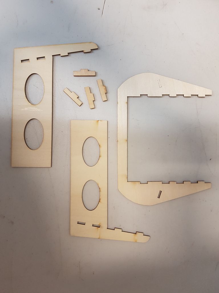
Started building my F-104 eventually and I have a few parts I received that I either have no idea what they are for or need confirmation of what I think they might be. Here goes the first batch. No idea what these are for....
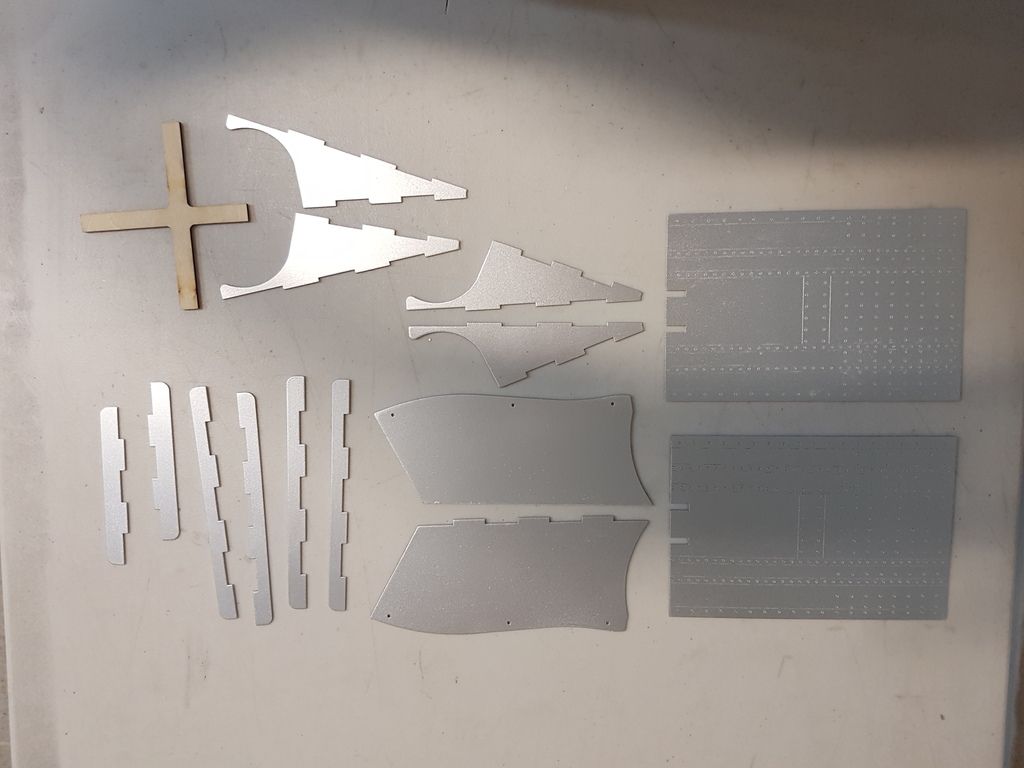
...also no idea what these silver painted balsa scale parts are for...
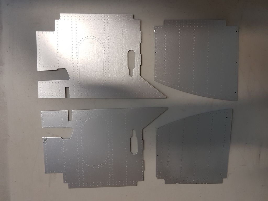
...or these...
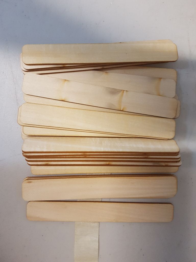
...now these I think is for me to use when lifting up the turbine to mount it higher, right? Otherwise they will be useful to mix paint with...
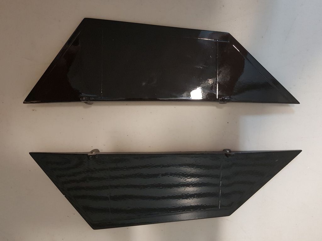
These two black ones I think are dorsal fins, except my model don't have any obvious mounting positions. Furthermore, I don't think the fullsize I am modelling had dorsal fins, only the single centerline fin underneath behind the wings...
Any additional comments and advice will be appreciated.
Thanks,
Jan
Started building my F-104 eventually and I have a few parts I received that I either have no idea what they are for or need confirmation of what I think they might be. Here goes the first batch. No idea what these are for....

...also no idea what these silver painted balsa scale parts are for...

...or these...

...now these I think is for me to use when lifting up the turbine to mount it higher, right? Otherwise they will be useful to mix paint with...

These two black ones I think are dorsal fins, except my model don't have any obvious mounting positions. Furthermore, I don't think the fullsize I am modelling had dorsal fins, only the single centerline fin underneath behind the wings...

Any additional comments and advice will be appreciated.
Thanks,
Jan
Last edited by Springbok Flyer; 03-21-2017 at 12:21 AM.

 03-21-2017, 09:05 AM
#3
My Feedback: (1)
Join Date: Dec 2002
Location: Brentwood Bay,
BC, CANADA
Posts: 96
Likes: 0
Received 2 Likes
on
2 Posts
Some of these pieces are in your second picture and some are in the third. It is like a 3D gig saw puzzle. The small strakes are used on the later model 104 like you will see if you google the Italian air force. I can try to take more pictures in it would help but once you start to fit the big bits in you will start to see where the smaller ones fit. Regarding the wood pieces in the first picture, I still have those left over as well. I do not know why SM cannot hire someone in North America to do a proper instruction manual.
03-21-2017, 09:58 AM
#4
My Feedback: (1)
Join Date: Dec 2002
Location: Brentwood Bay,
BC, CANADA
Posts: 96
Likes: 0
Received 2 Likes
on
2 Posts
Here is a picture of the speed brake compartment. The panel sits in the back. Not a great picture.
.
If you can order this book it is fabulous and shows great details on most versions of the F 104
03-21-2017, 02:01 PM
#5
Thread Starter
Join Date: Jun 2006
Location: Gold Coast, Queensland, AUSTRALIA
Posts: 1,469
Received 26 Likes
on
24 Posts
I cannot agree with you more - their current manual write-ups are simply inadequate and a total waste of time.
Thank you for giving me some direction with the silver pieces - I should be able to work it out from here on. A simple photo and a short explanation in the manual would have been so easy for SM.
Cheers,
Jan
03-21-2017, 02:06 PM
#6
Thread Starter
Join Date: Jun 2006
Location: Gold Coast, Queensland, AUSTRALIA
Posts: 1,469
Received 26 Likes
on
24 Posts
Cheers,
Jan
03-21-2017, 02:45 PM
#7
Thanks mate, I think I will end up with the same. However, as JJP pointed out, a simple explanation in the instruction manual would have been so easy for SM. It is also unclear why SM do not position some hard wood on the inside of the fuselage where these two dorsal fins can/should be mounted.
Cheers,
Jan
Cheers,
Jan

Last edited by dubd; 03-21-2017 at 02:51 PM.
03-21-2017, 04:17 PM
#8

If you haven't already seen it, have a look on this SM 104 thread from rccanucks. Trevor is a fantastic builder....
http://rccanucks.com/showthread.php?...ter-Behotec220
http://rccanucks.com/showthread.php?...ter-Behotec220
The following users liked this post:
DenisFerrari (09-13-2020)
03-21-2017, 06:54 PM
#10
 03-21-2017, 11:13 PM
#11
Thread Starter
Join Date: Jun 2006
Location: Gold Coast, Queensland, AUSTRALIA
Posts: 1,469
Received 26 Likes
on
24 Posts
If you haven't already seen it, have a look on this SM 104 thread from rccanucks. Trevor is a fantastic builder....
http://rccanucks.com/showthread.php?...ter-Behotec220
http://rccanucks.com/showthread.php?...ter-Behotec220
03-22-2017, 01:28 AM
#13
Thread Starter
Join Date: Jun 2006
Location: Gold Coast, Queensland, AUSTRALIA
Posts: 1,469
Received 26 Likes
on
24 Posts
The mystery of the wood pices in my first photo has now been solved. John from Skymaster has identified them as being the cockpit mounting kit.....please Skymaster, a little bit more information in your instruction manual will be so helpful!!
Cheers,
Jan
 03-22-2017, 05:57 PM
#15

My Feedback: (1)
Some of these pieces are in your second picture and some are in the third. It is like a 3D gig saw puzzle. The small strakes are used on the later model 104 like you will see if you google the Italian air force. I can try to take more pictures in it would help but once you start to fit the big bits in you will start to see where the smaller ones fit. Regarding the wood pieces in the first picture, I still have those left over as well. I do not know why SM cannot hire someone in North America to do a proper instruction manual.
 03-22-2017, 07:26 PM
#17

Join Date: Jan 2005
Location: CaloundraQueensland , AUSTRALIA
Posts: 493
Likes: 0
Received 2 Likes
on
2 Posts
The one in your photo Jan is a F-104G the only one that has 2 dorsal fins are the F- 104S the only reason I know is because I'm building a 1/4 scale one and all the documentation I got
Damo
Damo
Last edited by Damo260; 03-22-2017 at 07:30 PM.
03-23-2017, 12:47 PM
#20
Thread Starter
Join Date: Jun 2006
Location: Gold Coast, Queensland, AUSTRALIA
Posts: 1,469
Received 26 Likes
on
24 Posts
Cheers,
Jan
09-11-2017, 02:40 PM
#21
Thread Starter
Join Date: Jun 2006
Location: Gold Coast, Queensland, AUSTRALIA
Posts: 1,469
Received 26 Likes
on
24 Posts
Hi guys,
C of G; so where do you guys suggest I position that using a 25.5kg thrust engine? It would seem this spot is getting moved back as the thrust goes up.
Cheers,
Jan
C of G; so where do you guys suggest I position that using a 25.5kg thrust engine? It would seem this spot is getting moved back as the thrust goes up.
Cheers,
Jan
09-11-2017, 05:11 PM
#22
My Feedback: (1)
Join Date: Nov 2003
Location: Caracas, VENEZUELA
Posts: 551
Likes: 0
Received 0 Likes
on
0 Posts
Hi Jan,
The C of G is 145mm back from LE, do not use what Skymaster says. It's 40mm too far forward.
You also have to raise the engine up 50mm, in order to decrease the up thrust to 2 deg.
Jack
09-12-2017, 12:54 AM
#23
Thread Starter
Join Date: Jun 2006
Location: Gold Coast, Queensland, AUSTRALIA
Posts: 1,469
Received 26 Likes
on
24 Posts
Keep well my friend, maybe we can catch up again in another 20 years somewhere in the world at another jet meet.
Cheers,
Jan
11-06-2017, 03:08 AM
#24
Thread Starter
Join Date: Jun 2006
Location: Gold Coast, Queensland, AUSTRALIA
Posts: 1,469
Received 26 Likes
on
24 Posts
Hi guys,
Are any of you having problems with the retraction of the main undercarriage on your SM F-104? Or if you had problems, how did you sort it out?
I find that mine is going up, but not all the way, which then stop the main gear doors from not closing completely. When I push it by hand, it will go all the way and it does not feel like there is anything that restrict the movement.
Thank you for your suggestions and help.
Cheers,
Jan
11-06-2017, 03:56 AM
#25
Join Date: Aug 2012
Location: Mississauga, ON, CANADA
Posts: 13
Likes: 0
Received 0 Likes
on
0 Posts
Hi Jan
I had several issues with my 104 main gear not retracting well or fully. Ultimately, I had to disassemble the gear and found minor areas where it would bind due to slight interference with the fit or geometry. So it may pay off to disconnect the retract cylinder and move the gear by hand to find any binding points. By doing this I was able to find, clearance and lubricate the tight spots and finally get the gear to retract at 40 psi.
A second area to watch is the connection to the doors. It appears that the positioning of the pickup point and adjustment of the connecting link can have an effect on the last few inches of retract travel. Again, I found that everything needs to be well aligned and smooth for this to work well.
I am starting to work on my second 104 shortly and right now it is evident that it is binding as well. As well made as the gear is there are some minor interference points that need attention.
Finally, I switched to very thin shock oil for the hydraulics. The factory oil is good but in our cooler climate the gear was very slow so a change to thinner oil helped.
Cheers
Doug
Last edited by Mach5M5; 11-06-2017 at 03:57 AM. Reason: Removed duplicate signature.