


new monster boat projects

 07-10-2014, 07:00 AM
#27

Thread Starter
and here is the powertrain which will be installed into the 160cm size.
New designed gearbox with 4 counter rotating outputs, type 1 with everywhere 1:1, type 2 with an overdrive of 16% of the 2 outside outputs. Electric starter on an idea of Dieter Just / Germany (he has this style on his RAT HOUSE, pls. see my page). PowerSpark....as usual. Currently I am constructing the exhaust manifolds / headers.
New designed gearbox with 4 counter rotating outputs, type 1 with everywhere 1:1, type 2 with an overdrive of 16% of the 2 outside outputs. Electric starter on an idea of Dieter Just / Germany (he has this style on his RAT HOUSE, pls. see my page). PowerSpark....as usual. Currently I am constructing the exhaust manifolds / headers.
07-10-2014, 01:08 PM
#28
Member
Join Date: Dec 2010
Location: spring,
TX
Posts: 58
Likes: 0
Received 0 Likes
on
0 Posts
I envy all you guys, This has been an interesting post so far, I have not seen toys to be this huge so far. I have my v24 that I have installed the Zenoah 26pum from bonzi boat performance, but after all these small chats I am so wanting to have something like this in my garage. WoW
07-10-2014, 01:32 PM
#29
Senior Member
Join Date: Jan 2010
Location: Sanctuary PointNSW, AUSTRALIA
Posts: 358
Likes: 0
Received 0 Likes
on
0 Posts
looking impressive thomas, is werner doing the gearboxes? why the overspeed on the two outside? are you thinking on 2 different pitches of props?
looking forward to more posts mate.
regards mick.
looking forward to more posts mate.
regards mick.
07-10-2014, 09:59 PM
#30
Thread Starter
Mick,
Werner will not produce this type of gearbox. I do not know whether I's produce or not.
Overdrive at the oustside props: these props are not as deep in the water as the inside ones, they have less resistance. I thought I could use the same prop size as at the insiders if the revs are a bit higher...
07-11-2014, 12:51 AM
#31
Senior Member
Join Date: Jan 2010
Location: Sanctuary PointNSW, AUSTRALIA
Posts: 358
Likes: 0
Received 0 Likes
on
0 Posts
i would have thought a prop with a little less pitch on the outside drives would be in order, that way you would be putting a little less strain on the driveline? like the idea, very interesting to see how it all works out.
take care
take care
08-15-2014, 11:41 PM
#33
Thread Starter
Hello Mick,
currently we are investigating the costs (also shipping costs) for the complete 3m kit. When / if I have all data, I can tell a sales price and then I will see what will happen.
My main issue are the extreme shipping costs of the molds and the kits, but one of my neighbors is working in a shipper company, maybe I will get some cost reduction help.
Thomas
08-18-2014, 03:28 AM
#34

I think there are a lot more guys that would love to have one then will foot the bill, But for the guy that will I do not think the cost of shipping will be a issue,Matho any one can see you are very good at what you do and you love it,There will be some that will pay for it, the rest of us will just wish we had one.I know Bob Violet that makes jets and years ago he set the bar very high, he was a air traffic controller and said when he started making models he was not going to take a cut in pay.I DO NOT THINK HE HAS. I think if you make this happen you will do well and bring a whole new level to model boating.
08-19-2014, 03:05 AM
#35
Senior Member
Join Date: Jan 2010
Location: Sanctuary PointNSW, AUSTRALIA
Posts: 358
Likes: 0
Received 0 Likes
on
0 Posts
Thomas, I tend to agree with Tom, If you have a well built quality kit that no one else is doing then the customers will be prepared to pay what ever the shipping costs and kit costs that are to be paid for just to get hold of it.
I hope we get to see this project come to fruition.
I am sure if anyone can find a way , you can.
Regards Mick
I hope we get to see this project come to fruition.
I am sure if anyone can find a way , you can.
Regards Mick
09-04-2014, 12:02 AM
#37
Thread Starter
News of 3mCESA (the big one):
we are ableto produce the hull parts with vacuum technology which will create less weightand more stiffness because the resin will be better soaked into the layers(multiaxial).
Weight losswill be around 30% compared to the well known hand layer method.
Within nextweeks we will prepare the CAD data of the single parts, then the milling maystart
News of the1.6m CESA (the small one):
thisproject will be the next but with a different method, the plugs will be made inAustralia.
Currently Iam thinking about the negatives, the production method will be the hand layermethod.
Keep youinformed….
09-04-2014, 02:59 AM
#39
Senior Member
Join Date: Jan 2010
Location: Sanctuary PointNSW, AUSTRALIA
Posts: 358
Likes: 0
Received 0 Likes
on
0 Posts
Im glad this project is not going to get shelved Thomas,
I am in agreement with you on the infusion process, this not only saves weight but also time, the human mistake factor too. Little more messing around creating the bags , but well worth it.
https://www.youtube.com/watch?v=f7BogBB0NI8
I am playing around with this process, using silicone bags, less mess, less setting up and reusuable.... all good so far.
Lite RTM
https://www.youtube.com/watch?v=yTsXKGUdtCE
requires a lot of skill in making the Male mold, plus laying down the Reinforcement in the correct layering is absolutely critical, too thick and you risk getting dry spots, too thin and you risk closing up the mold.
Least the silicone bags have a fair bit of flexibility. Of course using normal bags is fine too.
Just my two cents.....
Regards Mick
09-04-2014, 04:19 AM
#40
Thread Starter
the guy who will perform this method for the big one is working as a CF-specialist in a company which produces wings for military aircrafts...... and it is a difference to use this
method at a 1.0 meter hull or at a 3.0m hull...... you must have the correct knowledge and equipment
Mick: I will keep you informed and I have never thought to cancel the project. You are in!!
method at a 1.0 meter hull or at a 3.0m hull...... you must have the correct knowledge and equipment
Mick: I will keep you informed and I have never thought to cancel the project. You are in!!
09-04-2014, 04:43 AM
#42
Thread Starter
Hi Mart,
I have decided to go this way. We will see when the first hull comes out or: just look and wonder....... if we'd to reinforce: we will do that for sure.
This boat will be absolutely awesome and I do not want to sell any bad quality..... my plan is to drive to the fabrication site (approx 1200km distance) when
these guys are ready to produce.... quality insurance......
09-04-2014, 06:08 PM
#45
Senior Member
Join Date: Mar 2002
Location: Kingsport,
TN
Posts: 1,803
Likes: 0
Received 0 Likes
on
0 Posts
I dont agree about infusion as its proven its weaker than hand laying using normal good quality epoxy and then bagging which is much more impact resistant also,you need to use a thinned down resin with infusion which in itself isnt as strong as normal epoxy so for that reason bagging is better.
The rtm method is very expensive,male moulds are not so hard once you have the female, been there done it lol.Still havent found a reason to change all my moulds to this process though but for Mathos projects it might be an idea but very costly to build the tooling.Im currently building hulls using vinylester resin and this material i like.
The rtm method is very expensive,male moulds are not so hard once you have the female, been there done it lol.Still havent found a reason to change all my moulds to this process though but for Mathos projects it might be an idea but very costly to build the tooling.Im currently building hulls using vinylester resin and this material i like.
Vacuum is by far the best way to "clamp" the layup and resin in place over a mold. It's biggest advantage is ensuring there is not excessive resin in the lay up and there are no air voids which result in a weakened part..
As far as Thomas's project goes, there will indeed be more start up costs but in the end his product will be more consistent and I would venture to guess far less waste from bad pulls. I agree that the process is expensive but to intimate that hand laminating is superior is just plain wrong. JMO
02-27-2018, 05:28 AM
#46
Thread Starter
meanwhile we have had some progress. Because this is an international hobby project it costs some more time than expected, we have CAD designer in UK, Sitzerland and Germany, positive and mold producers in Australia and Italy, kit producer in Italy
121" version:
will be produced in Italy by a carbon fiber specialist who works in a company which produces wings of windmills.
The positive is ready to mill but during the design of the hardware we've found out that the stern pod must be changed.
This has been done by our CAD designer, we are waiting for the data.
Hardware has been concepted by me and transferred into CAD-data:
- drives
- trim tabs
- rudders (CAD work ongoing)
The first models will get 2 RAT HOUSEs each. To be able to perform an easy package study I have made 2 powertrain dummies.
You may check the pics in the attachment if you'd like
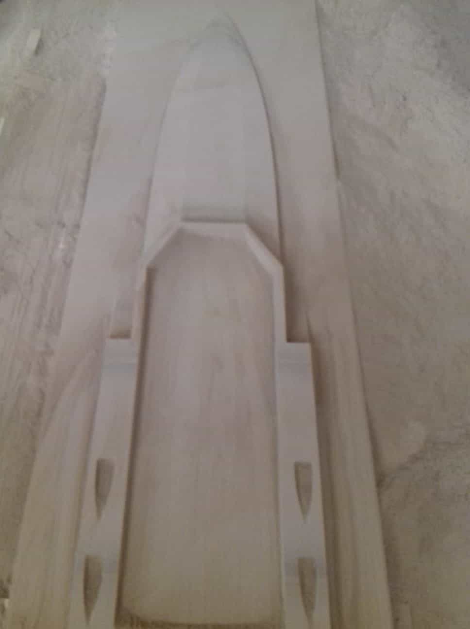
65" version:
Mick in Australia is working on the positive, see attachments. The hardware will be a bit more easy because we can scale that down from the bigger model.
121" version:
will be produced in Italy by a carbon fiber specialist who works in a company which produces wings of windmills.
The positive is ready to mill but during the design of the hardware we've found out that the stern pod must be changed.
This has been done by our CAD designer, we are waiting for the data.
Hardware has been concepted by me and transferred into CAD-data:
- drives
- trim tabs
- rudders (CAD work ongoing)
The first models will get 2 RAT HOUSEs each. To be able to perform an easy package study I have made 2 powertrain dummies.
You may check the pics in the attachment if you'd like
65" version:
Mick in Australia is working on the positive, see attachments. The hardware will be a bit more easy because we can scale that down from the bigger model.
07-11-2018, 12:35 AM
#47
Thread Starter
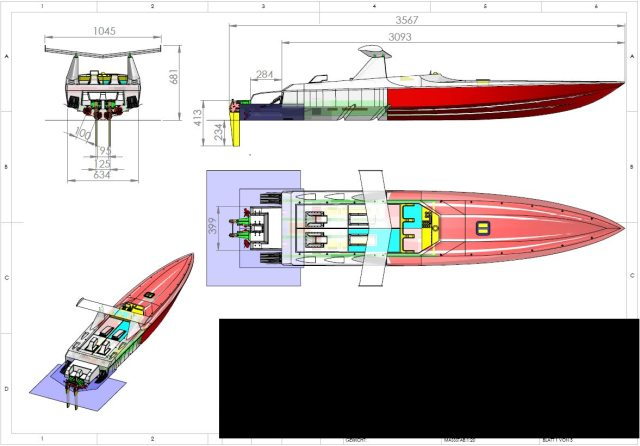
data of Big CESA1882
update: now we have finished our design work of the big model, we are currently preparing alls 3D and 2D data to get all needed parts produced.
Attached you'll find an overview which shows the size of the Big CESA1882. All values are in millimeters, e.g. 3567mm = 140"
The work on the small model (165cm = 60") has been stopped because the plug-producer has some trouble. When we have done the work on the big one I will
take care of the small one
 01-04-2019, 02:07 AM
#50
Thread Starter
Guys,
a bit time went by w/o telling news. Here we are:
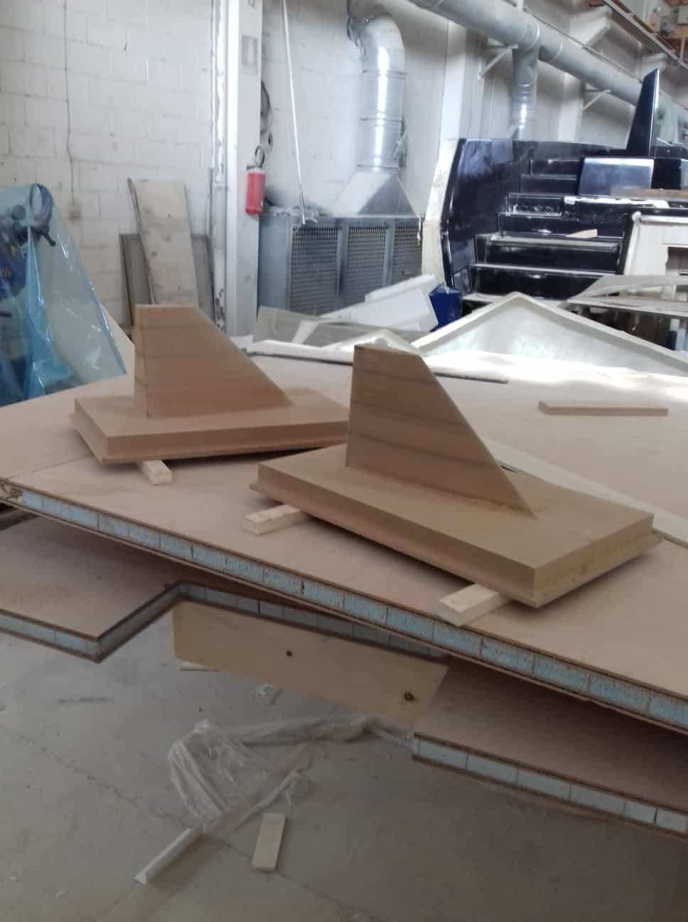
we had found out that there was a mistake at the stern pod. So we decided to make a new one. To save time we have printed that part, the pics show the result.
Hardware is completely designed now, more than 100 different parts
- 2 rudder sets
- 2 trimtabs
- 4 drives
- 1 rope box
- 2 prop safer for spare props
- 4 internal rails to fix engines, tanks, rc-box, battery box etc
- craning devices
- stanchions
at the end 400 up to 500 single parts expected.
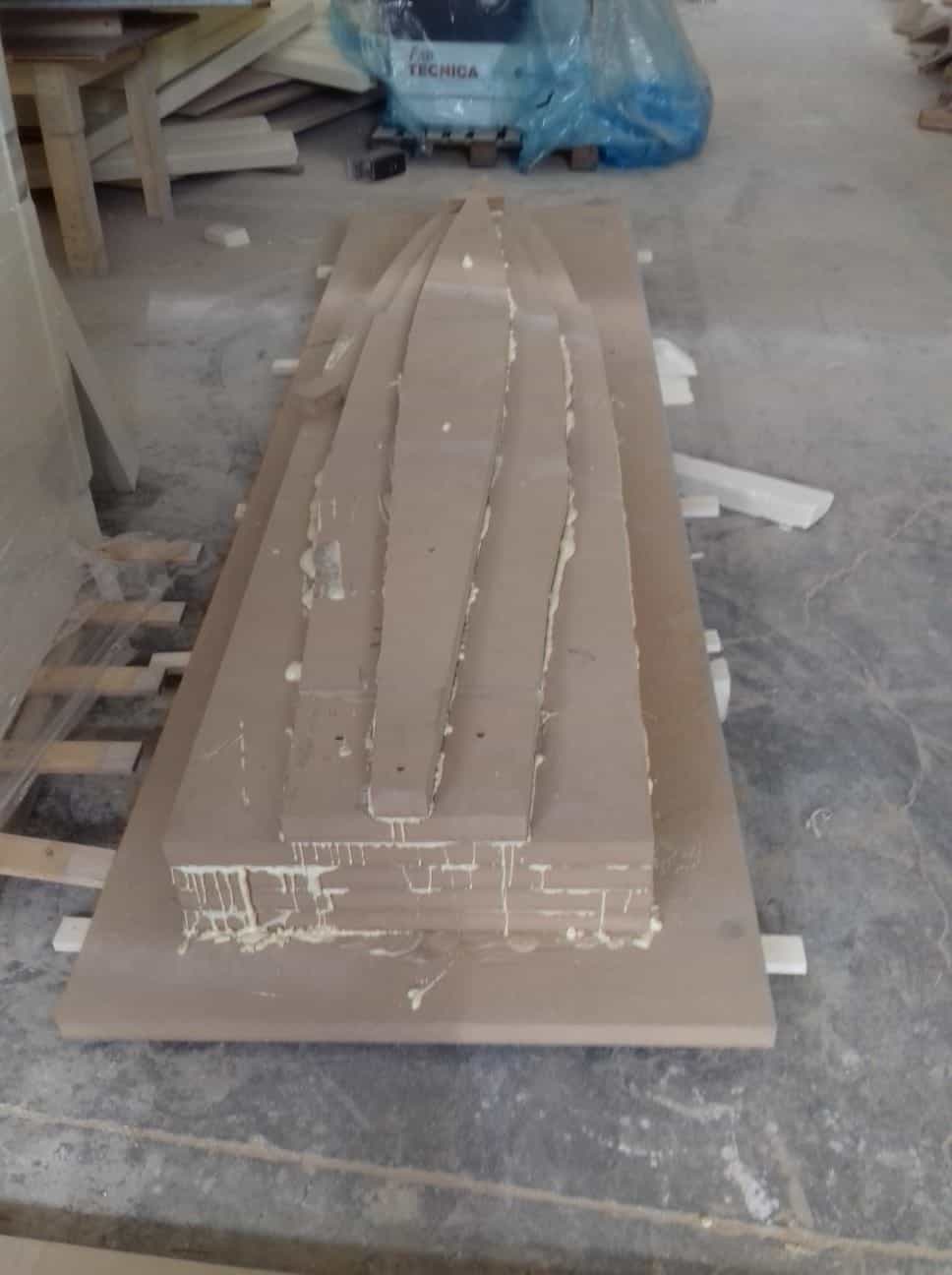
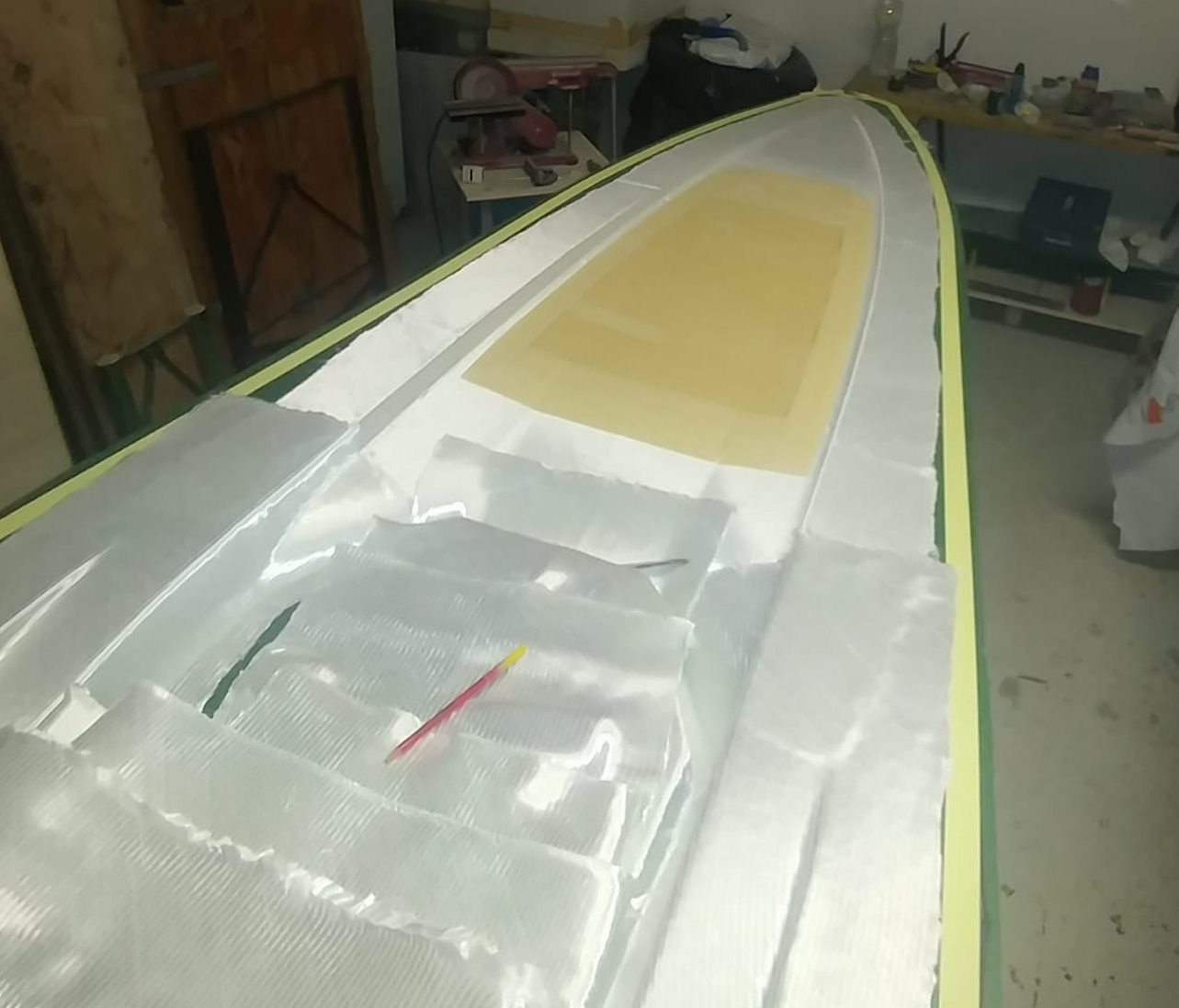
First hull is in the production phase now, we use not the hand layer method, here we use the infusion method, which is usual in the aircraft industry. Reason: the result is less weight at better durability and stiffness. That means the layers will be put dry into the mold, then this will be covered and sealed by a plastic sheet, then a vacuum pump starts. The result is very low pressure - nerby zero - and this sucks the resin into the layers, This ensures 100% saturation of the layers.
The pics show a bit how it works.
tbc


a bit time went by w/o telling news. Here we are:
we had found out that there was a mistake at the stern pod. So we decided to make a new one. To save time we have printed that part, the pics show the result.
Hardware is completely designed now, more than 100 different parts
- 2 rudder sets
- 2 trimtabs
- 4 drives
- 1 rope box
- 2 prop safer for spare props
- 4 internal rails to fix engines, tanks, rc-box, battery box etc
- craning devices
- stanchions
at the end 400 up to 500 single parts expected.
First hull is in the production phase now, we use not the hand layer method, here we use the infusion method, which is usual in the aircraft industry. Reason: the result is less weight at better durability and stiffness. That means the layers will be put dry into the mold, then this will be covered and sealed by a plastic sheet, then a vacuum pump starts. The result is very low pressure - nerby zero - and this sucks the resin into the layers, This ensures 100% saturation of the layers.
The pics show a bit how it works.
tbc