


Stuffing a DLE 20 into a Hobbistar 60
 12-01-2013, 03:08 PM
#26
Senior Member
Thread Starter

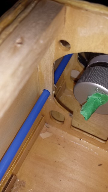
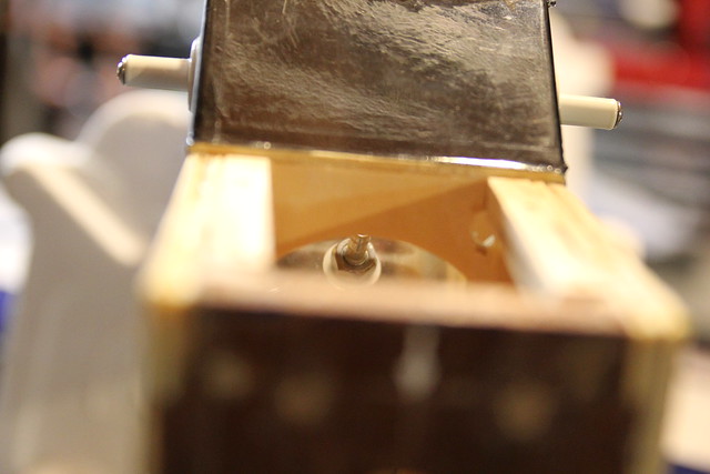
Eyeballing the fuel line passage from the side...
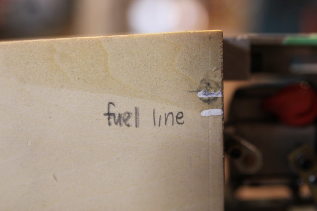
... and the top.
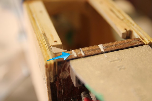
All the while, the fuel inlet is protected from dust and debris.
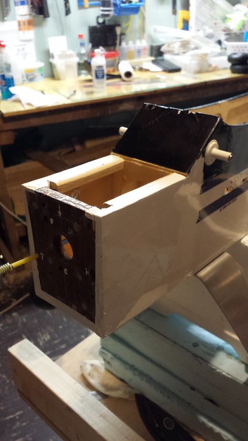
Here's the plane with engine, muffler, prop and spinner. Going to check prop clearance.
... and the top.
All the while, the fuel inlet is protected from dust and debris.
Here's the plane with engine, muffler, prop and spinner. Going to check prop clearance.
 12-01-2013, 03:14 PM
#27
Senior Member
Thread Starter
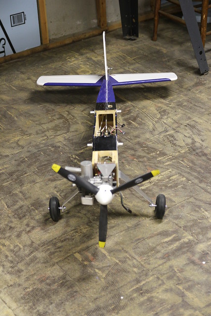
Looks good with all three wheels on the ground...
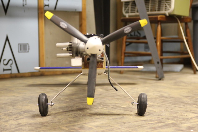
Looks good with the fuse parallel to the ground too.

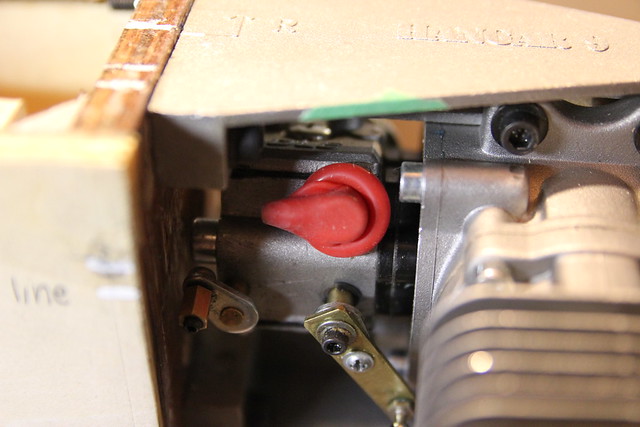
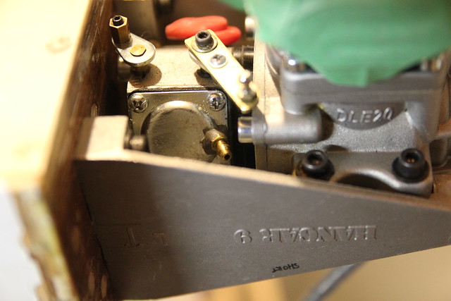
Here's a look at the choke and throttle arms and the fitting for carburetor equalization.
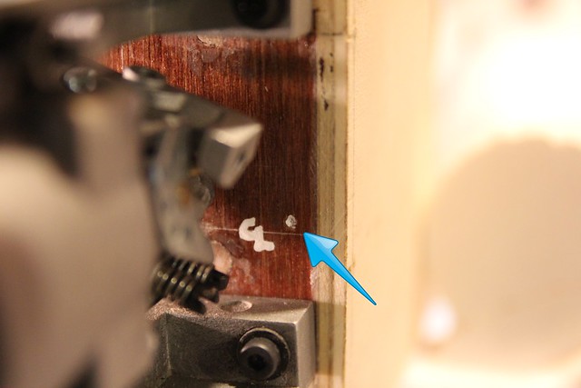
Here's the drilling location for the hall sensor lead.
Looks good with the fuse parallel to the ground too.
Here's a look at the choke and throttle arms and the fitting for carburetor equalization.
Here's the drilling location for the hall sensor lead.
12-01-2013, 03:17 PM
#28
Senior Member
Thread Starter
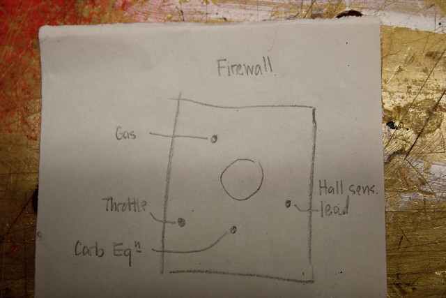
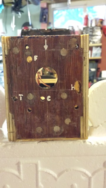
This is a rough diagram of the drilling locations on the firewall. It was helpful in keeping things straight.
All the holes marked for drilling...
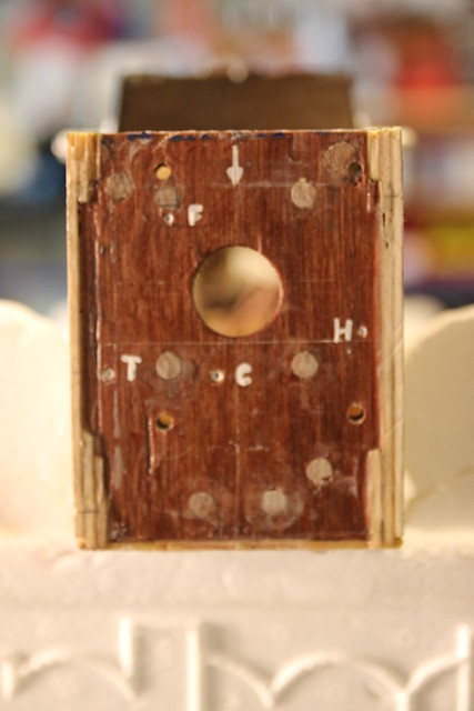
...and after drilling.
All the holes marked for drilling...
...and after drilling.
12-01-2013, 03:44 PM
#29
Senior Member
Thread Starter
I replaced some of the tri-stock I had to remove for the engine mounting bolts.
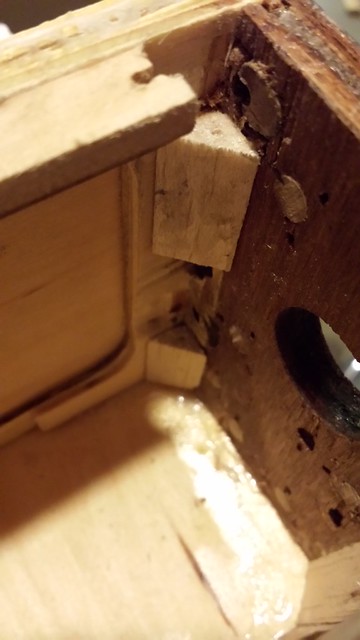
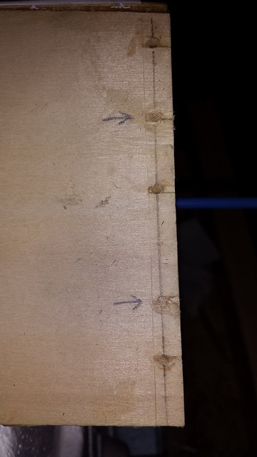
I figure pinning the firewall in a couple of extra spots on the port side will help compensate for the missing tri-stock.
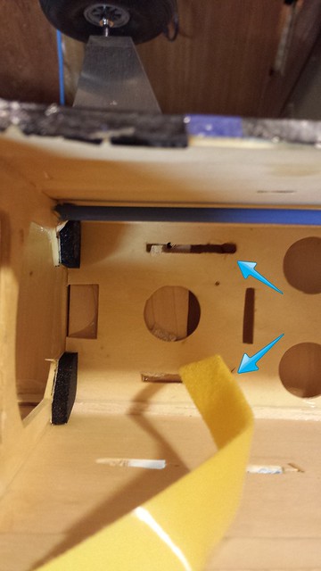
I wanted to run the throttle push rod tube through these bulkheads...
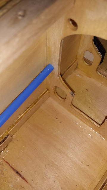 .
.
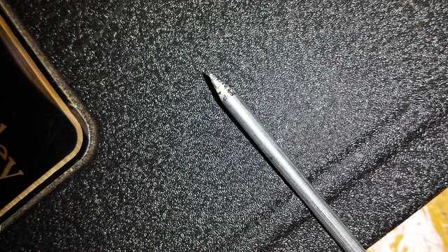
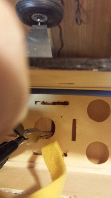
The location and tight fit made drilling difficult. I decided to try sharpening a small push rod.
I figure pinning the firewall in a couple of extra spots on the port side will help compensate for the missing tri-stock.
I wanted to run the throttle push rod tube through these bulkheads...
.The location and tight fit made drilling difficult. I decided to try sharpening a small push rod.
12-01-2013, 03:48 PM
#30
Senior Member
Thread Starter
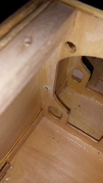
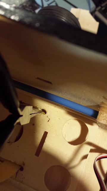
With a little perseverance, the pilot hole was drilled.
To enlarge the hole, I selected a piece of music wire about the same size as the required drill bit, and sharpened that.

It was a little heavy for the drill.
That worked too. Tube in!
To enlarge the hole, I selected a piece of music wire about the same size as the required drill bit, and sharpened that.
It was a little heavy for the drill.
That worked too. Tube in!
12-01-2013, 04:13 PM
#31
Senior Member
Thread Starter
Here's the servo end of the throttle linkage.
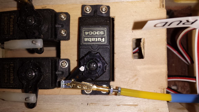
I added a support block for the throttle tube.

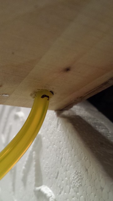
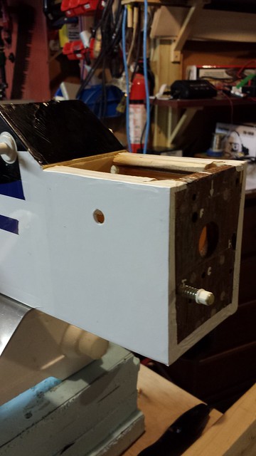
Throttle push rod exiting the tube at the firewall.
Drilling a hole at the bottom near the front for the vent line fitting.
I added a support block for the throttle tube.
Throttle push rod exiting the tube at the firewall.
Drilling a hole at the bottom near the front for the vent line fitting.


 12-02-2013, 05:32 AM
#34
Senior Member
Thread Starter
12-02-2013, 05:33 AM
#35
Senior Member
Thread Starter
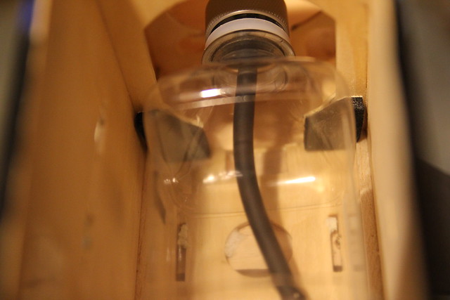
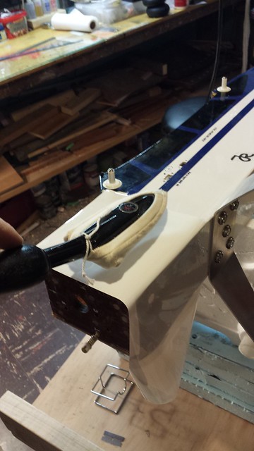
Got some more work done on the fuel tank too.
I was lucky enough to score a Fiji water bottle in the 360 mL size - they're pretty hard to come by. I ordered the cap a while back, along with some Viton tubing and a felt clunk.
It's important to ensure that the clunk doesn't snag on the bottle in any attitude.
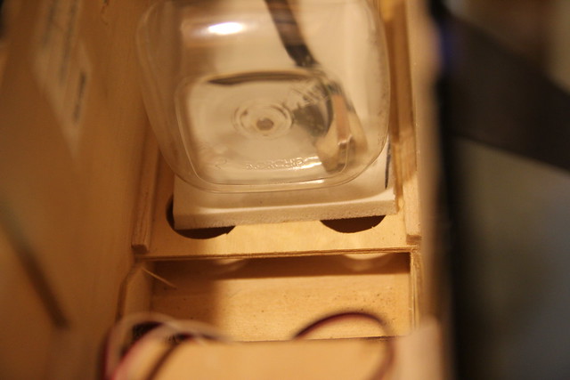
I also cut some foam pads to cushion the tank inside the fuselage. For the front of the tank...
...and beneath it.
I was lucky enough to score a Fiji water bottle in the 360 mL size - they're pretty hard to come by. I ordered the cap a while back, along with some Viton tubing and a felt clunk.
It's important to ensure that the clunk doesn't snag on the bottle in any attitude.
I also cut some foam pads to cushion the tank inside the fuselage. For the front of the tank...
...and beneath it.
12-02-2013, 05:40 AM
#36
Senior Member
Thread Starter
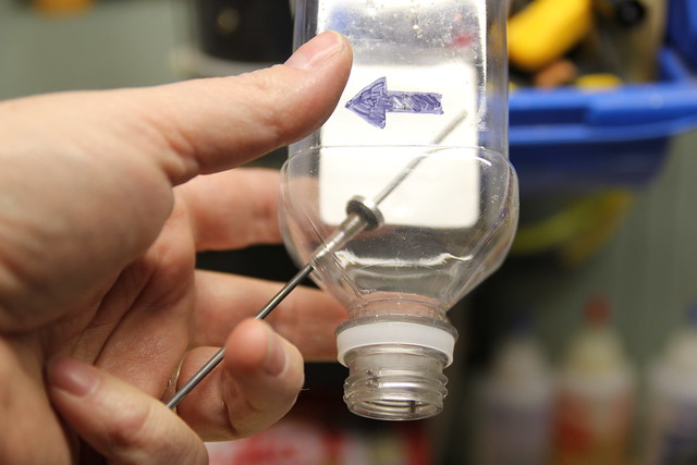
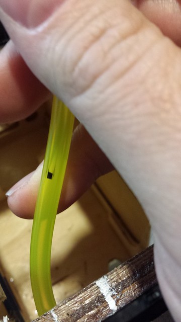
Next step - the barb for the vent line. This will be a two-line system with the fill line connecting to the engine supply line via a "T". Start by drilling a hole - I use a brad point drill bit and turn it by hand.
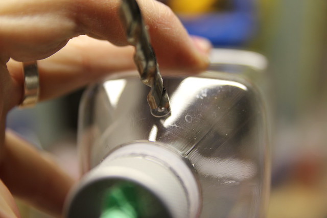
I spin the bit backwards (counter-clockwise) until the spurs scribe the outer diameter. Then I switch directions.
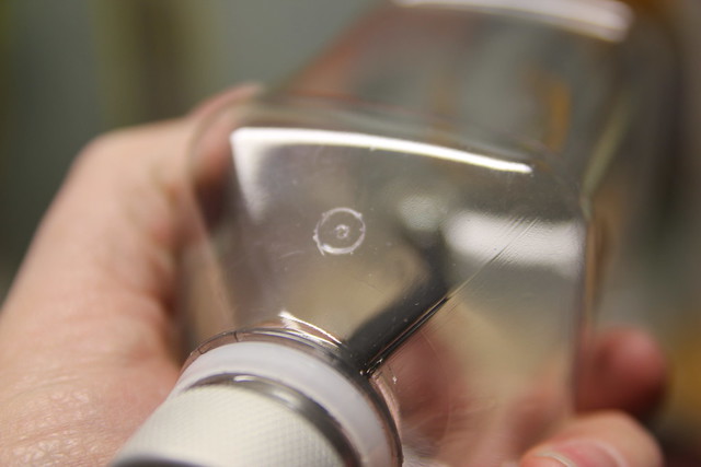
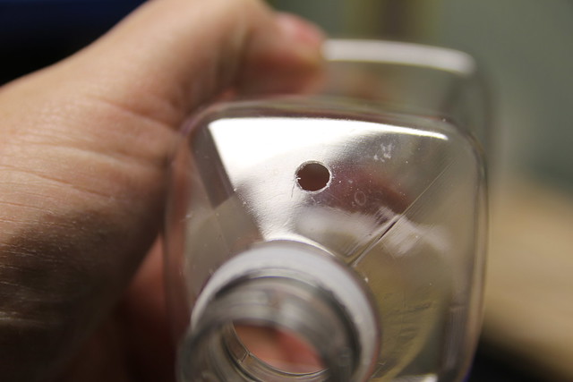
The result is a nice, clean hole.
I spin the bit backwards (counter-clockwise) until the spurs scribe the outer diameter. Then I switch directions.
The result is a nice, clean hole.
12-02-2013, 05:46 AM
#37
Senior Member
Thread Starter
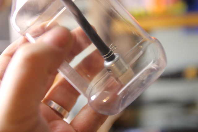
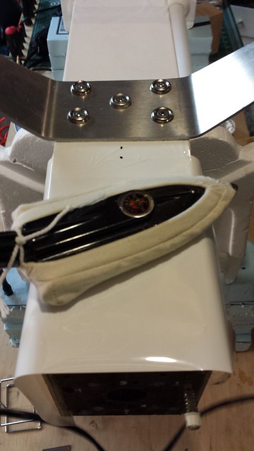
Now for the barb. I start by putting it in the tank.
A piece of wire is a great help in snagging the barb and getting it to the hole.
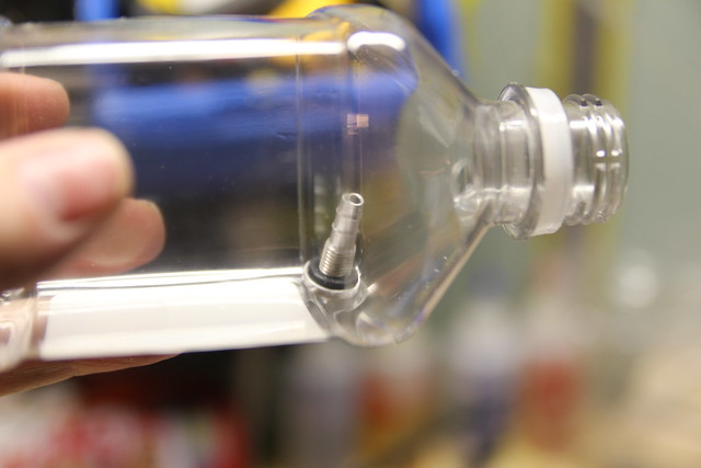
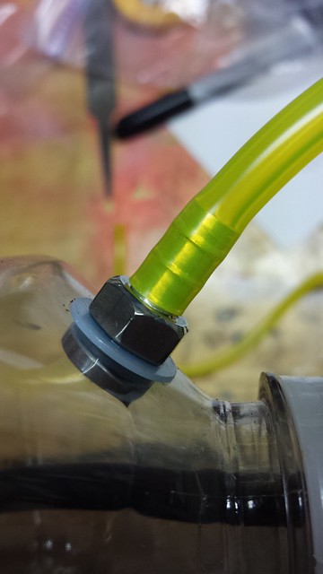
Pull the barb through, slide on the plastic washer and thread on the retaining nut. There is a keyway inside the barb for a hex driver so you can hold the body in place while you tighten the nut.
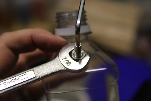
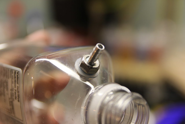
Installation complete.
A piece of wire is a great help in snagging the barb and getting it to the hole.
Pull the barb through, slide on the plastic washer and thread on the retaining nut. There is a keyway inside the barb for a hex driver so you can hold the body in place while you tighten the nut.
Installation complete.
12-02-2013, 06:01 AM
#38
Senior Member
Thread Starter
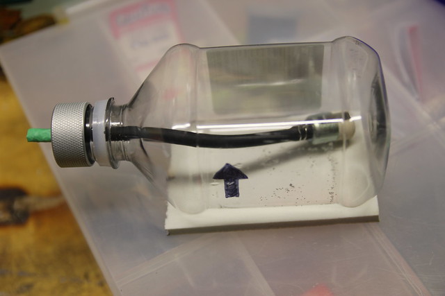
I chose the barb location with installation of the tank in mind. The main thing is, it clears the former against which the front of the tank rests. View from the back...
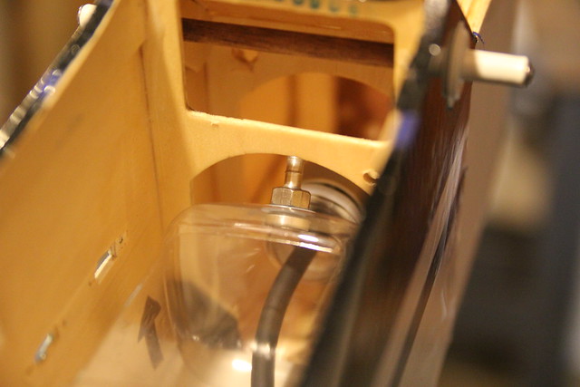
... and the front.
The vent line will be routed over the top of the tank and down the side before connecting to the vent fitting; this will prevent gas from leaking out when it contacts the barb. The two line system has worked well for me in the past. Here's a diagram I created when plumbing my 50cc SBach 342 - the only difference is the bottle size.
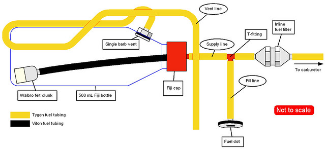
I use a pickup filter in my gas jug; the extra filter between the T-fitting and the carb is cheap insurance.
... and the front.
The vent line will be routed over the top of the tank and down the side before connecting to the vent fitting; this will prevent gas from leaking out when it contacts the barb. The two line system has worked well for me in the past. Here's a diagram I created when plumbing my 50cc SBach 342 - the only difference is the bottle size.
I use a pickup filter in my gas jug; the extra filter between the T-fitting and the carb is cheap insurance.
12-02-2013, 08:03 AM
#39

My Feedback: (4)
Join Date: Jan 2002
Location: Westhampton Beach,
NY
Posts: 860
Likes: 0
Received 0 Likes
on
0 Posts
Love the graphics and the detail of your work!
Where did you get the metal cap and that barb your using on the Fiji water bottle/tank? makes for a very slick setup!
Thanks,
Bill S.
Where did you get the metal cap and that barb your using on the Fiji water bottle/tank? makes for a very slick setup!
Thanks,
Bill S.
Last edited by Twin_Flyer; 12-02-2013 at 08:05 AM.
12-02-2013, 10:04 AM
#40
Senior Member
Thread Starter
I got those parts from a Canadian supplier - Thunderbolt RC. I can't say enough good things about these guys.
Fiji Aluminum Water Bottle Fuel Tank Cap
Aluminum Vent - Single Barb
Both are from PSP Manufacturing - excellent stuff. According to the website you can buy the products directly from them.
12-02-2013, 07:24 PM
#41
Senior Member
Thread Starter
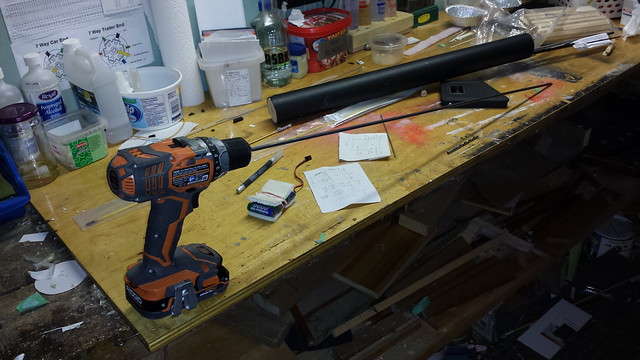
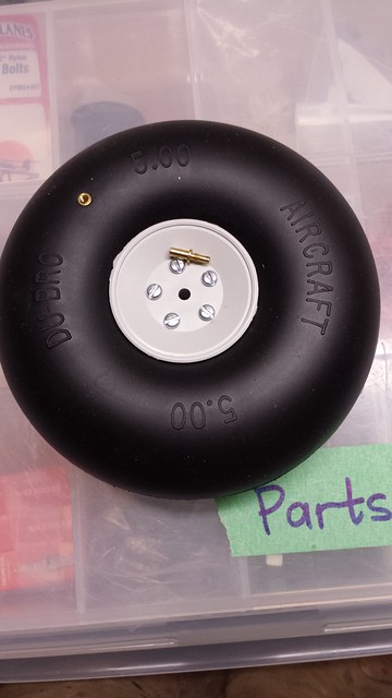
It was suggested to me that I pick up some larger tires to increase ground clearance. These oughta do!
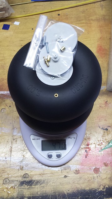
New wheel against old by JD and Beastlet, on Flickr
This airplane came with 1-3/4" tires. I soon found I needed bigger ones for my club's grass strip, so I upgraded to 3-1/2" tires. The new ones are 5"!
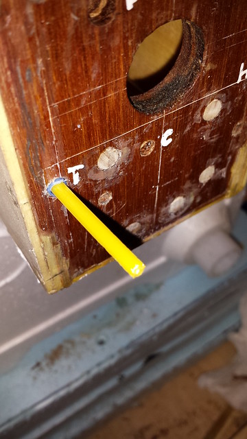
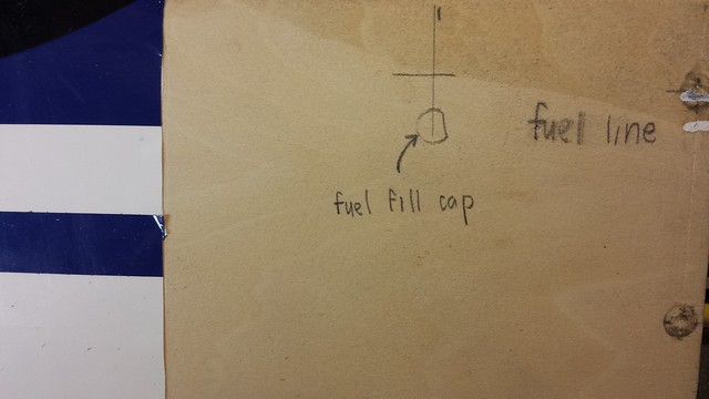
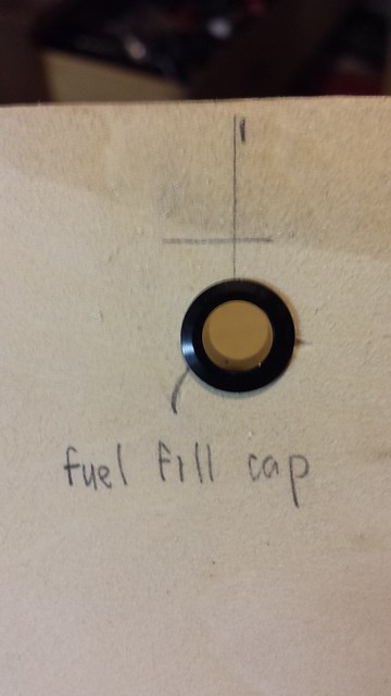
Drilling the hole for the fuel dot now. The vertical line is centred between the firewall and the windscreen and the horizontal line marks the bottom of the top hatch mounting block inside the fuse. This looked like a good position to me.
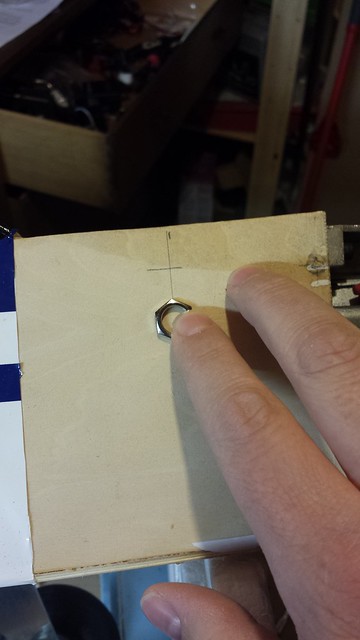
Marked (the little dent is where my finger was).
New wheel against old by JD and Beastlet, on Flickr
This airplane came with 1-3/4" tires. I soon found I needed bigger ones for my club's grass strip, so I upgraded to 3-1/2" tires. The new ones are 5"!
Drilling the hole for the fuel dot now. The vertical line is centred between the firewall and the windscreen and the horizontal line marks the bottom of the top hatch mounting block inside the fuse. This looked like a good position to me.
Marked (the little dent is where my finger was).
12-02-2013, 07:31 PM
#42
Senior Member
Thread Starter
I started the hole with my brad point bit as usual.
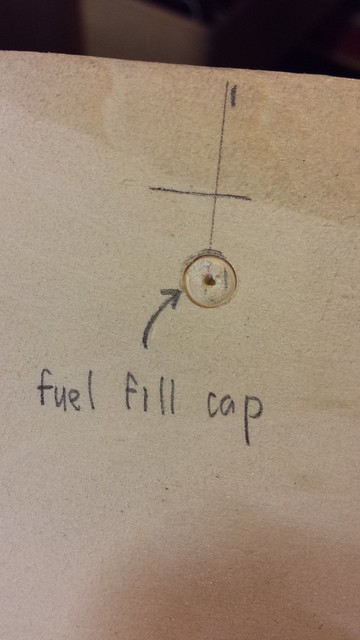
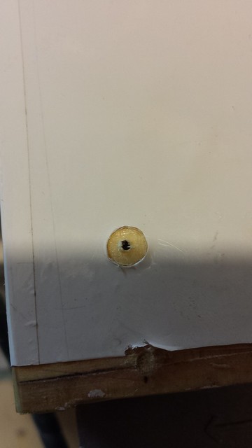
One problem - the hole needs to be 3/8" and my brad point set tops out at 1/4", so I had to use a standard twist drill. Mostly by accident I found a new way (new to me) to cleanly enlarge a hole in thin material with a twist drill: Chuck the bit in a power drill and set the drill to reverse. Hold the bit near the opening and pull all the way back on the trigger. Ease the spinning bit into the hole and apply gentle pressure; the bit reams layers out of the hole instead of tearing. The result:
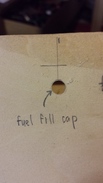
And here's the fuel dot barrel.
One problem - the hole needs to be 3/8" and my brad point set tops out at 1/4", so I had to use a standard twist drill. Mostly by accident I found a new way (new to me) to cleanly enlarge a hole in thin material with a twist drill: Chuck the bit in a power drill and set the drill to reverse. Hold the bit near the opening and pull all the way back on the trigger. Ease the spinning bit into the hole and apply gentle pressure; the bit reams layers out of the hole instead of tearing. The result:
And here's the fuel dot barrel.
12-02-2013, 07:39 PM
#43
Senior Member
Thread Starter
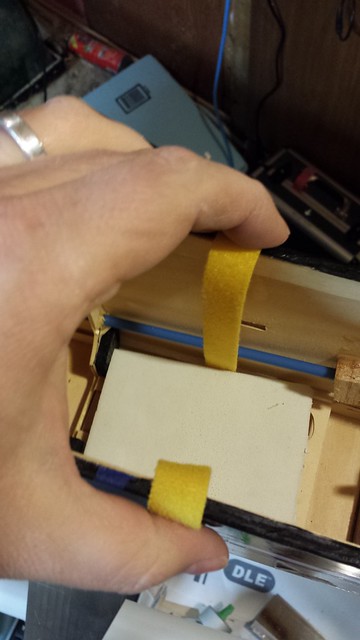
Next, a little more work on the fuel tank, starting with the installation of a velcro strap. First step was select a suitable rotary bit and enlarge a couple of slots in the tray.
As you can see above, I fed the the velcro into one slot. I used some small pliers to help it along through the tray and to pull it out the other end.
Presto.
As you can see above, I fed the the velcro into one slot. I used some small pliers to help it along through the tray and to pull it out the other end.
Presto.
12-02-2013, 07:44 PM
#44
Senior Member
Thread Starter
On to the vent line. I chose a route and marked it for length.
While the tank was still in I made a mark at the back for a tie-down for the rear loop of the vent line.
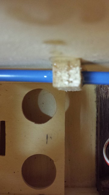
Hole drilled and zip tie inserted. The zip tie with hold the back of the vent line down, but I won't make it too tight.
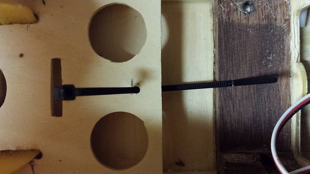
While the tank was still in I made a mark at the back for a tie-down for the rear loop of the vent line.
Hole drilled and zip tie inserted. The zip tie with hold the back of the vent line down, but I won't make it too tight.
12-02-2013, 07:48 PM
#45
Senior Member
Thread Starter
With the vent line cut to length, I installed in on the barb on the fuel tank.
As hard as it was to get on, there is no way that line is going to come off by itself. Still, a little redundancy is good.
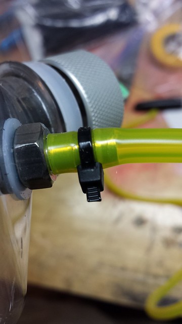
As hard as it was to get on, there is no way that line is going to come off by itself. Still, a little redundancy is good.
12-02-2013, 07:54 PM
#46
Senior Member
Thread Starter
Before I could finalize the fuel dot and vent line fittings, I needed to recover the bare section of fuselage near the firewall. I have a glass plate for cutting covering. It was in the clearance centre of my local glass store and cost me about ten bucks. Here it is, clamped and cleaned.
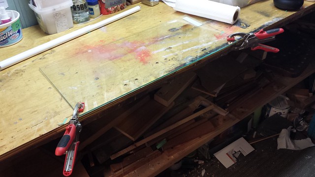
Next, I cut out the piece I needed - 13-1/4" by 5-1/4".
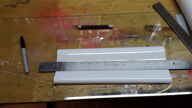
A razor blade to peel up a corner of the backing...
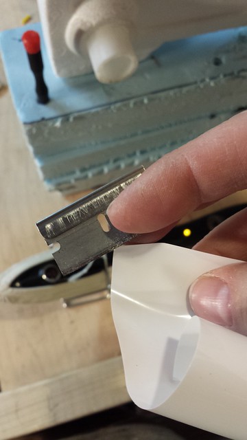
... and here we go. I started with the bottom (note the alignment marks).
Next, I cut out the piece I needed - 13-1/4" by 5-1/4".
A razor blade to peel up a corner of the backing...
... and here we go. I started with the bottom (note the alignment marks).
12-02-2013, 07:59 PM
#47
Senior Member
Thread Starter
On to the port side...
Just about done.
Fuel dot location.
I can finish up the trim covering later, and there some other areas that need attention. Next, however, I'll continue plumbing the fuel system.
Just about done.
Fuel dot location.
I can finish up the trim covering later, and there some other areas that need attention. Next, however, I'll continue plumbing the fuel system.
12-03-2013, 03:29 AM
#48
Senior Member
Thread Starter
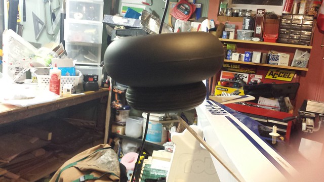
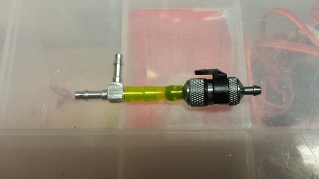
I was wondering how to fill these tires - I don't have the right pump and my LHS doesn't either.
Turns out that if you screw in the adapter...
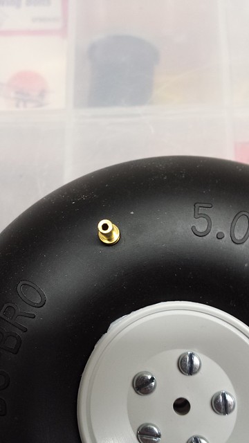
... take your compressor with blow gun attached and hold it to the adapter, you can fill the tire (this is just the money shot - I held the blow gun in one hand and the tire in the other while I was inflating it).
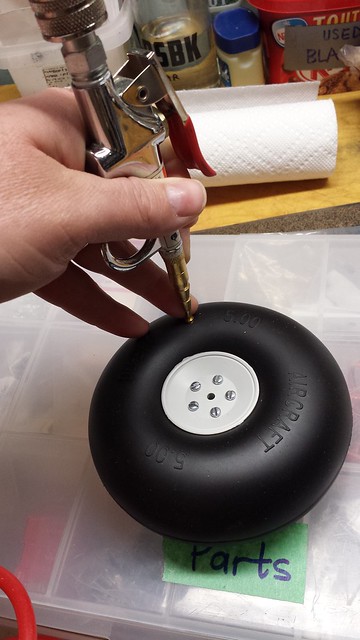
A couple of words on this approach...
- Set your compressor's output low - I used 20 PSI and it filled the tires very quickly.
- Fill the tire just a little firmer than you want it - some air will leak out of the adapter before you can unscrew it.
Turns out that if you screw in the adapter...
... take your compressor with blow gun attached and hold it to the adapter, you can fill the tire (this is just the money shot - I held the blow gun in one hand and the tire in the other while I was inflating it).
A couple of words on this approach...
- Set your compressor's output low - I used 20 PSI and it filled the tires very quickly.
- Fill the tire just a little firmer than you want it - some air will leak out of the adapter before you can unscrew it.
12-03-2013, 03:41 AM
#49
Senior Member
Thread Starter
On to the plumbing. i started by connecting the T fitting to the fuel filter with a short piece of tubing. The tubing is Tygon - the large size.
Next, I connected a length of tubing to the engine, fed it through the firewall and marked it for cutting.
Supply line is on and zip ties are installed - we're getting there.
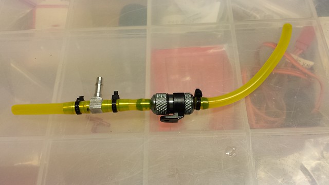
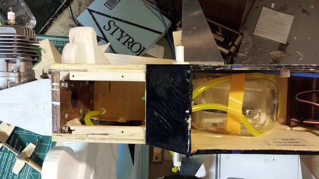
Here's the fuel system ready to install. From left to right - vent line, fill line, supply line.
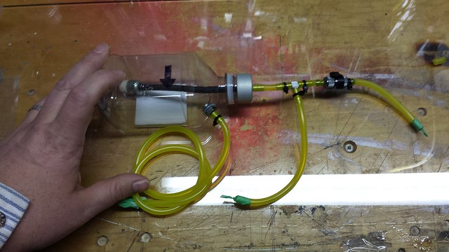
Next step - electronics: receiver, ignition, ignition cutoff and batteries.
Next, I connected a length of tubing to the engine, fed it through the firewall and marked it for cutting.
Supply line is on and zip ties are installed - we're getting there.
Here's the fuel system ready to install. From left to right - vent line, fill line, supply line.
Next step - electronics: receiver, ignition, ignition cutoff and batteries.