


Eletronic engine syncronizer **SUPPORT **
 11-26-2010, 01:58 PM
#901

My Feedback: (23)

Join Date: Sep 2004
Location: Fayetteville,
GA
Posts: 1,413
Likes: 0
Received 0 Likes
on
0 Posts
ORIGINAL: peterduplessis
Bill never responds to email .... do you have a telephone number?
Bill never responds to email .... do you have a telephone number?
 11-26-2010, 03:05 PM
#902
Junior Member
My Feedback: (9)
Join Date: Mar 2005
Location: Pretoria Gauteng, SOUTH AFRICA
Posts: 26
Likes: 0
Received 0 Likes
on
0 Posts
Well I'm pleased to hear that he does support you guys ... I ordered units from him in October, and he responded 16Nov. I confirmed my order the same day and have heard nothing since. I will try again....Thanks!
11-30-2010, 07:23 PM
#903
My Feedback: (5)

Join Date: Feb 2002
Location: Torrington, CT
Posts: 71
Likes: 0
Received 0 Likes
on
0 Posts
Has anyone used the Twinsync with a DLE-30 engine yet? Can the Twinsync use the engine's pickup or do you need to use the one that comes with the Twinsync?
01-10-2011, 05:11 AM
#904
Member
Join Date: Sep 2007
Location: aberdeen, UNITED KINGDOM
Posts: 55
Likes: 0
Received 0 Likes
on
0 Posts
HI GUYS HAVE JUST SPENT A FEW HOURS READING THIS TOPIC START TO FINISH ....DEF A DEVICE WORTH HAVING ....CONGRATULATIONS TO BILL ....NEED ONE FOR MY ASM LANCASTER AND WONDER WHICH VERSION IS RECOMENDED.
GRAHAM
ABERDEEN
SCOTLAND
GRAHAM
ABERDEEN
SCOTLAND
01-11-2011, 01:02 AM
#905
Member
Join Date: Aug 2009
Location: RobinaQld, AUSTRALIA
Posts: 56
Likes: 0
Received 0 Likes
on
0 Posts
Hey Graham,
There is only one version but you can get some optional accessories if you wish. I just received mine and am happy to say that it is a very professionaly built unit. Bill has been great with communication and assistance.
details can be found at www.troybuiltmodels.com
Kind regards
Craig
There is only one version but you can get some optional accessories if you wish. I just received mine and am happy to say that it is a very professionaly built unit. Bill has been great with communication and assistance.
details can be found at www.troybuiltmodels.com
Kind regards
Craig
01-11-2011, 01:07 AM
#906
Member
Join Date: Sep 2007
Location: aberdeen, UNITED KINGDOM
Posts: 55
Likes: 0
Received 0 Likes
on
0 Posts
thanks craig,
have just received mail from bill, he never mentioned assessories though.....
what ya building dude?
graham
have just received mail from bill, he never mentioned assessories though.....
what ya building dude?
graham
01-11-2011, 01:12 AM
#907

I got my sync about a week ago too, It's a well built piece and Bill was nothing but helpful. The accessories I got is a RPM display and glow driver set. Those are the only ones I think there are for the sync, but I could be wrong
01-11-2011, 05:37 AM
#908
Member
Join Date: Sep 2007
Location: aberdeen, UNITED KINGDOM
Posts: 55
Likes: 0
Received 0 Likes
on
0 Posts
thanks peter
yeah i need the displays and glow starts...4 of them...building the asm lancaster...
ill mention this to bill when he responds
many thanks
graham
yeah i need the displays and glow starts...4 of them...building the asm lancaster...
ill mention this to bill when he responds
many thanks
graham
01-11-2011, 05:43 AM
#909
graham,
the Lancaster is a 4 engine beast.... man you are tha man! Just as a not you will need two synchs for that, there are notes on how to wire it up for 4 engine synching.... You'll need 2 glow driver sets too... Bill will be able to tell you though, just make sure to mention that you are synching 4 engines..
01-11-2011, 06:12 AM
#910
Member
Join Date: Sep 2007
Location: aberdeen, UNITED KINGDOM
Posts: 55
Likes: 0
Received 0 Likes
on
0 Posts
peter, thanks again ...checkout my photobucket site for pics
http://s824.photobucket.com/albums/z...rahamaberdeen/
btw
graham
http://s824.photobucket.com/albums/z...rahamaberdeen/
btw
graham
01-11-2011, 06:52 AM
#911
so the slo gin, is that to keep the nerves calm or does it make the jet go faster [X(]?
Btw, I'm in the process of building the Top Flite DC-3. Maybe one day I'll get my hands on B-17 plan and build one...
I've been looking at Russin aviation examples and i thought this was a cool video http://www.youtube.com/watch?v=DVqilOx6lNQ
Some of the discussions are interesting
Btw, I'm in the process of building the Top Flite DC-3. Maybe one day I'll get my hands on B-17 plan and build one...
I've been looking at Russin aviation examples and i thought this was a cool video http://www.youtube.com/watch?v=DVqilOx6lNQ
Some of the discussions are interesting
01-11-2011, 04:01 PM
#912
Member
Join Date: Sep 2007
Location: aberdeen, UNITED KINGDOM
Posts: 55
Likes: 0
Received 0 Likes
on
0 Posts
peter,
great video .....i can recomend the tf b25 flies superb no vices check out youtube "b25 at inverurie" got a glitch towards end of flight and thought i lost it...panic and immediate approach and land.....2.4 gig ...dont think so ... ill put my hands up and admit i need thicker glasses!!
better stop chatting on this site as its more for twin sync support....sorry bill
graham
02-15-2011, 02:57 PM
#914
Senior Member

Join Date: May 2009
Location: Jacksonville,
FL
Posts: 542
Likes: 0
Received 0 Likes
on
0 Posts
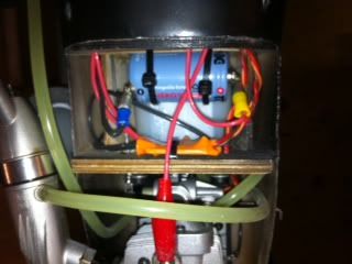
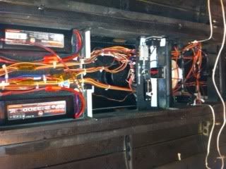
Ok.....So I have the Quadsync installed in my B-17G. I didnt want each of the drivers in the nacelles so they are all lined up in the center of the wing under the fusalage next to the Quadsync. I was kind worried about running too small of wire two the glow drivers so I ran some pretty heavy copper strand stuff I had handy from my surround sound speakers to the glow plugs. It is about 18g.
I am also concerned about the size of the switch needed and how to charge the battery back up. I read in here somwhere you can burn up the drivers while charging with a programable charger if it is connected to the drivers. I made a 5 sub C, NiCad, 1.2V, 8500mAh battery with a Deans plug attached. I also bought a Deans plug power disconnect. It has a heavy Deans plug/key you put in to power up.
So the questions I have are the following.
1. How large of wire did I need to run to:
a. the three feet to the outer drivers?
b. the two feet to the inner drivers?
c. the two feet from the battery to all four drivers?
2. How heavy does the switch need to be?
3. How many amp/milliamps will four glow plugs pull?
4. How long will the battery last at full charge?
Thanks
SR
 02-15-2011, 04:34 PM
#916
Senior Member
Join Date: May 2009
Location: Jacksonville,
FL
Posts: 542
Likes: 0
Received 0 Likes
on
0 Posts
BTW...Why is this thread called "Eletronic engine syncronizer**SUPPORT **"? Changing the name of the thread to add Twinsync/Quadsync and going from Eletronic to Electronic/Digital would make it easier to find. I think the original poster can make changes.
SR
SR
02-23-2011, 05:12 AM
#917

Join Date: Jul 2006
Location: NESLE nse, FRANCE, METROPOLITAN
Posts: 58
Likes: 0
Received 0 Likes
on
0 Posts
Hi, SR
If I understand it well ... [>:]
you have 4 Stroke engines ( looking they are Saitos ...) SO let's count 4 amps per Glow plug ...
from that, you should use some .75 sq mm wire as a minimum not to reduce too much the voltage ( think to the voltage survey Bill placed ... )
no need to use different wire gauges ...
personnaly I would use 1 sq mm ( easier to find Xtra flexible wire for measuring purpose ) from the batt to the glow modules and to the Glow Plugs.
resistance will be .021 Ohms per meter ( 3 ft ) of cable ...
so outer glows voltage drop will be ... 2 times * .021 ohms /3 * (2+3) feet * 4 amps = .28 volts ... becomes significant !
Alain
If I understand it well ... [>:]
you have 4 Stroke engines ( looking they are Saitos ...) SO let's count 4 amps per Glow plug ...
from that, you should use some .75 sq mm wire as a minimum not to reduce too much the voltage ( think to the voltage survey Bill placed ...
)no need to use different wire gauges ...
personnaly I would use 1 sq mm ( easier to find Xtra flexible wire for measuring purpose ) from the batt to the glow modules and to the Glow Plugs.
resistance will be .021 Ohms per meter ( 3 ft ) of cable ...
so outer glows voltage drop will be ... 2 times * .021 ohms /3 * (2+3) feet * 4 amps = .28 volts ... becomes significant !
Alain
02-23-2011, 01:11 PM
#918
Member
Join Date: Sep 2007
Location: aberdeen, UNITED KINGDOM
Posts: 55
Likes: 0
Received 0 Likes
on
0 Posts
speed racer....fyi in my lanc i have fitted a 4500 type c nimh power supply for onboard glows, these are in the nacells... i currently have the same arrangement in my b25 and invader, this provides enough glow power for 3 weekends flying before needing charged, i am going to post my install on our club forum ......amfc.co.uk .... just at the point of finishing the online build topic so give me a couple of days and it will be there...Personally i would not go putting nicads anywhere else...
anyway thanks to bill for his very prompt service ,many emails and also a telephone call with advice on my quad sync queries... if only other things in life went so well !
graham
anyway thanks to bill for his very prompt service ,many emails and also a telephone call with advice on my quad sync queries... if only other things in life went so well !
graham
03-06-2011, 09:51 AM
#920
My Feedback: (35)
Join Date: Dec 2001
Location: Clinton, CT
Posts: 104
Likes: 0
Received 0 Likes
on
0 Posts
Hey Guys,
I'm just finishing my Ziroli P-38 and I'm wondering how you are mounting the pickup on the engines? I'm using two DA-50s.
I'm just finishing my Ziroli P-38 and I'm wondering how you are mounting the pickup on the engines? I'm using two DA-50s.
03-06-2011, 01:08 PM
#921
Member
Join Date: Sep 2007
Location: aberdeen, UNITED KINGDOM
Posts: 55
Likes: 0
Received 0 Likes
on
0 Posts
hi bud ....regarding your query...
Im not sure about the da 50s ....but for general info
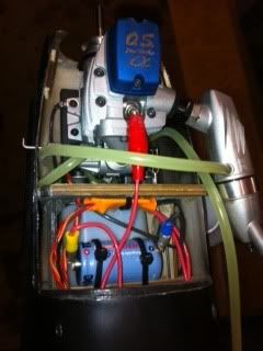
on my asm lancaster with 4 x os 72 alphas i had the same issue as you...not very keen on mounting sensors on ply / pc board etc due to distance from engine lugs etc so i came up with this which so far has not caused any issues...
position sensor wires nice flat and even, with pick up side of detector, dont think it makes a diffrence which side.....
place some cling film or similar on a flat surface, place sensor with detection side upwards, with cables nice and neat, pour thick cyano over sensor and a couple of mm of cable, then push firmly down with a thin peice of balsa, 2-3mm is ideal and activate the cyano if required.
peel the cling film off of the sensor and with a dremmel trim the balsa / cyano close to the contour of the sensor / lead.
turn sensor over and as the surface of cyano should be flat, cyano a thin piece of THIN ply to this side, and again dremmel to contour.
cyano THIN balsa to the ply and again trim to contour.
finally on the detector face gently sand away the first balsa fixed until cyano / trace balsa / sensor is just visible, this will give a dead flat face, supported with ply and balsa....
Bore the prop driver to to take the diametric magnets (obliously as close to circumfrence of driver as possible)
I then placed the detector over the magnet and tie wraped it to the crank case above the front bearing. it is up to you whether you, as i did run some thin cyano into the surface balsa to harden up a bit or not, The object of the balsa above the ply is to enable some firm grip from the tie wrap as the balsa will compress. i for security ran some cyano around the tie wrap and the end result is 1mm clearance above prop driver, a very short firm mount for the sensor and minimum vibration.
i have tested this method in the air when i was running in the engines in my great planes Shoestring and after 14 flights no adverse problems were encountered.... i have yet to balance my props on my lancaster so i will take a pic for you of finished install .......
my lanc now complete and test flight will be 17th april, mean time i have a few weekends doing pre flight tests / setups etc
regards
graham
Im not sure about the da 50s ....but for general info
on my asm lancaster with 4 x os 72 alphas i had the same issue as you...not very keen on mounting sensors on ply / pc board etc due to distance from engine lugs etc so i came up with this which so far has not caused any issues...
position sensor wires nice flat and even, with pick up side of detector, dont think it makes a diffrence which side.....
place some cling film or similar on a flat surface, place sensor with detection side upwards, with cables nice and neat, pour thick cyano over sensor and a couple of mm of cable, then push firmly down with a thin peice of balsa, 2-3mm is ideal and activate the cyano if required.
peel the cling film off of the sensor and with a dremmel trim the balsa / cyano close to the contour of the sensor / lead.
turn sensor over and as the surface of cyano should be flat, cyano a thin piece of THIN ply to this side, and again dremmel to contour.
cyano THIN balsa to the ply and again trim to contour.
finally on the detector face gently sand away the first balsa fixed until cyano / trace balsa / sensor is just visible, this will give a dead flat face, supported with ply and balsa....
Bore the prop driver to to take the diametric magnets (obliously as close to circumfrence of driver as possible)
I then placed the detector over the magnet and tie wraped it to the crank case above the front bearing. it is up to you whether you, as i did run some thin cyano into the surface balsa to harden up a bit or not, The object of the balsa above the ply is to enable some firm grip from the tie wrap as the balsa will compress. i for security ran some cyano around the tie wrap and the end result is 1mm clearance above prop driver, a very short firm mount for the sensor and minimum vibration.
i have tested this method in the air when i was running in the engines in my great planes Shoestring and after 14 flights no adverse problems were encountered.... i have yet to balance my props on my lancaster so i will take a pic for you of finished install .......
my lanc now complete and test flight will be 17th april, mean time i have a few weekends doing pre flight tests / setups etc
regards
graham
03-07-2011, 01:06 PM
#924
Member
Join Date: Sep 2007
Location: aberdeen, UNITED KINGDOM
Posts: 55
Likes: 0
Received 0 Likes
on
0 Posts
bo ingram / rolling circle
posted some pics for you both, you can check out my photobucket site at http://s824.photobucket.com/albums/z...rahamaberdeen/
hope these are of some help
graham
from outer face
1 tie wrap ( he he !)
2 balsa hardened with thin zap cyano
3 very thin mirralite ply etc
4 sensor
5 thin balsa/thick cyano encompassing the sensor and lead over the cable heat shrink, with balsa sanded off upon completion so you can just see the grain of balsa and barely see the sensor
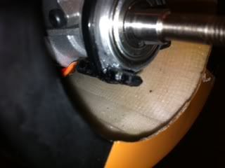
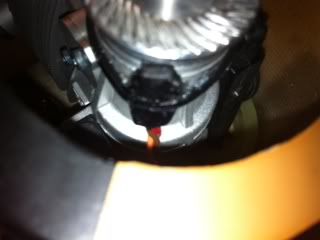
fit prop driver with diametric magnet positioned so if you have engine cut the prop windmills to compression strole and the magnet stops well away from sensor...THIS IS IMPORTANT see sync manual....gently fasten the sensor to the crankcase and play arround with position to get the optimum sensitivity, once happy, once again some thick cyano and activator, around tie wrap and under sensor to mould to crankcase profile, if you want run some around tiewrap and into the tiewrap grip to lock permanantly. as i have said i gave all 4 engines with sync attatched a run in period in my shoestring, 14 flights each engine and there was no movement etc evident and sensor checked out fine when fitted to lancaster so i feel confident with this method but obviously, there must be variations of this idea so have a think, or as arnie says " trust me"
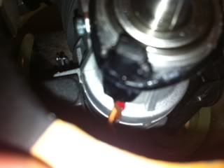
you can just make out the diametric magnet at 3 o clock
posted some pics for you both, you can check out my photobucket site at http://s824.photobucket.com/albums/z...rahamaberdeen/
hope these are of some help
graham
from outer face
1 tie wrap ( he he !)
2 balsa hardened with thin zap cyano
3 very thin mirralite ply etc
4 sensor
5 thin balsa/thick cyano encompassing the sensor and lead over the cable heat shrink, with balsa sanded off upon completion so you can just see the grain of balsa and barely see the sensor
fit prop driver with diametric magnet positioned so if you have engine cut the prop windmills to compression strole and the magnet stops well away from sensor...THIS IS IMPORTANT see sync manual....gently fasten the sensor to the crankcase and play arround with position to get the optimum sensitivity, once happy, once again some thick cyano and activator, around tie wrap and under sensor to mould to crankcase profile, if you want run some around tiewrap and into the tiewrap grip to lock permanantly. as i have said i gave all 4 engines with sync attatched a run in period in my shoestring, 14 flights each engine and there was no movement etc evident and sensor checked out fine when fitted to lancaster so i feel confident with this method but obviously, there must be variations of this idea so have a think, or as arnie says " trust me"
you can just make out the diametric magnet at 3 o clock
03-09-2011, 08:08 PM
#925
My Feedback: (35)
Join Date: Dec 2001
Location: Clinton, CT
Posts: 104
Likes: 0
Received 0 Likes
on
0 Posts
Hey Graham,
Thanks for the Pics. Last night I got the pickup mounted (pic 1), I got some opinions from some friends and one of them said it was OK to drill and tap the end of the engine body( like the ignition pick up) and mount it the same way. So tonight I took off the one I did last night and remounted it tonight. This definitely is the way to go. I'll lock tight and goop it down once my batteries come in and I can put it together and power it up,
Thanks for the Pics. Last night I got the pickup mounted (pic 1), I got some opinions from some friends and one of them said it was OK to drill and tap the end of the engine body( like the ignition pick up) and mount it the same way. So tonight I took off the one I did last night and remounted it tonight. This definitely is the way to go. I'll lock tight and goop it down once my batteries come in and I can put it together and power it up,