


3 Wheeled Radio Controlled Large Mower Build.
 11-07-2011, 11:04 AM
#1
Junior Member
Thread Starter
Join Date: Sep 2005
Location: Berkshire, UNITED KINGDOM
Posts: 19
Likes: 0
Received 0 Likes
on
0 Posts
6 November 2011.
Well its finally time to start my winter project.
Hurray!! I have been looking forward to this years winter build.
Spending my evenings in my workshop hiding away from the wife.
Firstly please excuse my grammar and spelling during this build. I have never been that good at spelling and writing so what you read is as good as its going to get.
Ok now that I have got that off my chest.
Introduction
This year I am going to build a big Radio Controlled mower totally from scratch.
I plan to build the mower to the best of my ability and at the end of the project I hope to have a brand new machine. It will cost me a lot less than a brand new machine as any machine with a large cut size will cost thousands of pounds or dollars.
My first decision was the design for the machine. Which design should I build? A traditional garden tractor, a zero turn 4 wheeled mower a 3 wheel zero turn machine etc etc. Lots of options.
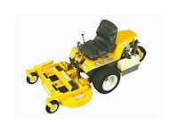
I ended falling in love with the Walker mower design using 2 large front wheels and a big rear caster type wheel.
What set this project going in the first place was the finding of 2 electric wheelchairs up for grabs in a local shop.


When I first got the chairs I didn’t know what to do with them at the time so I stripped them down for spares ready for my winter project.
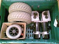
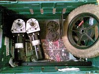
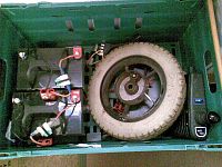
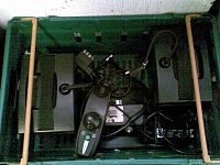
The 2 wheelchairs are in good working order so they are ideal to power my lawn mower.
At this time I have not yet decided how to power the cutter deck. I have 3 choices but each with there own problems. 1. Power with 24 volt motors, 2 Power using hybrid technology. Electricity to power the motors and supplied by a petrol generator. 3 Finally a engine to power the blades.
I will discuss this later on in the build.
One thing that has been decided and that is the wheels are driven by 24 volt motors.
Part 1 Wheels.
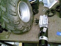
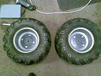
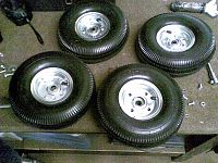
I started buying various parts for this project. My first purchase was a set of 4 quad bike wheels found on ebay. On most 2wd quads the front wheels are a different size and are much taller than the rears. I wanted a really rough tread pattern for my tractor rather than a lawn saver type tyre.
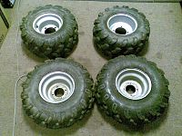
These wheels have some serious tread on them as you can see. They will give me loads of grip on the grass hills I have to mow especially when the grass is wet.
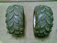
Out of the 4 wheels I decided to use the 2 wider rear tires, they are less tall than the fronts making them easier on the motors when in use.
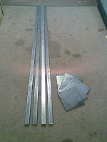
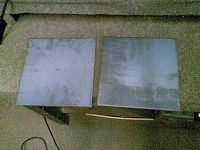
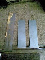
My second purchase was some bits of steel. I ordered some squares of 6mm plate and 4 lengths of box section for the chassis. Enough to get the project moving.
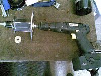
When I offered the motors up to the wheels some large hub adapters were required to fit them properly to the motors.
This was going to be a big task considering I don’t own a lathe.
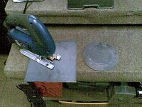
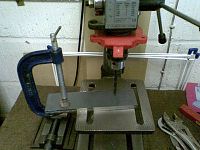
The first job is to cut the 6mm plates to fit on to the wheels. After measuring up and finding the dead center point of the square plate I drilled a small hole in the center. I then cut the circles out of the 6mm plate.
This was very hard going. I don’t know if you have ever cut 6mm plate using a jigsaw? It took me ages to cut each one and it felt like I was wearing it away rather than cutting it. After a packet of blades and a lot of swearing the discs were finally cut.

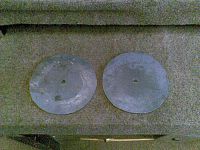
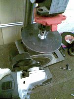
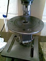
I now needed to make the discs perfectly round. But I don’t have a lathe. No worries as I had already drilled the center hole, I fitted a nut and bolt and locked the disc on my pillar drill. Once the disc was spinning I gave the disc a good grind with my angle grinder.
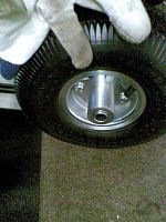
Once they were perfectly round I measured out the wheel nut PCD’s and drilled the holes to fit the wheels.
Time to fit the discs to the wheels to check that they fit.

Spot on first time.
They are a perfect fit as well.
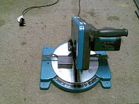
The next bit was to cut the hub spacer out of 50mm steel box section. After measuring up I cut the box section to size. I cut the steel box with a special steel cutting rage mitre saw as it cuts the steel perfectly square just like wood. Straight through in seconds.
I used part of the original hubs which were fitted to the original wheels on the chair as they have a keyway to lock them onto the motor shaft.

Time to weld the box section to the original hub. I used a threaded rod to clamp the box section to the hub.

Finally I now have two hubs ready to be welded to the wheel discs. This was a tricky job as the discs needed to be exactly in the center. If I welded them in the wrong place the wheels would turn like a old Laurel and Hardy pram.
I used my threaded rod again to clamp the discs to the newly made hubs.

After a lot of measuring and checking I welded the box section to the discs.
Time to find how good the new hubs were. I Put the hubs on my cordless drill and gave them a good spin.
Awesome job! When the discs were spinning there was very little movement and they were only a very small bit out of center. As the wheels only turn slowly you wouldn’t notice it. You might feel it if you were spinning them at 100mph.
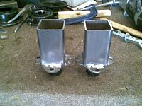
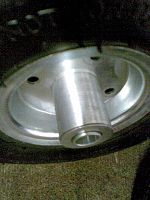
The last job was to drill out the center of the discs as I have to fit a nut inside to fix the original hubs to the motor axles. The hole needs to be big enough to allow a socket to fit through to the inside hub.
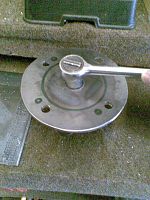
Job done! Two completed extra long motor hubs.

Time to fit the motors to the wheels.
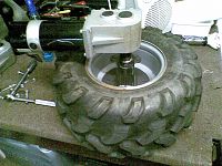
The new extra long wheel hubs are a perfect fit and it was time to give the new wheels a spin with the wheel chair motor. I set up the electrics on the bench and clamped the motor in the vice.
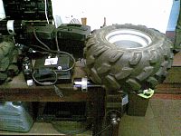
The wheels spin perfectly with very little movement.
Im very pleased with my first efforts building the wheel mounting hubs.
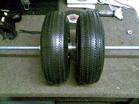
I put the wheels on the floor to see how wheels look with the motors.
They look great.
The tires are very wide and will make the machine look big and chunky.
The next task is to build the large rear caster wheel for the machine.
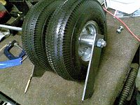
I decided to use 10 inch pneumatic wheels for the big caster.
Its very difficult trying to buy a ready made caster of this size as the caster needs to be as wide as possible for use on grass.
The first job is to make the 2 wheels ready for a big caster. When you buy wheels they have a off set to one side making them suitable for mounting on sack barrows, trolleys alike. So I brought 4 wheels so I could use 2 of the offset bearings on the other wheels with my caster.
Once all bolted together I used a threaded bar for the axle on the caster.
Once the wheels were ready and pumped up it was time to cut the steel for the caster.
I used my special rage bench saw which can easily cut steel plate up to 6mm thick.

Once cut up the steel is ready for drilling.
I clamped the plates together so that the holes were in the same place on both plates.
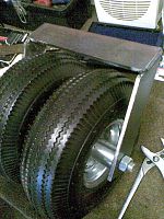
Now that the holes are drilled I can work out the correct angle for the sides of the caster. The caster turns when you change direction so swivel bearing needs to be at the back of the wheels.

Once lined up I welded the caster bracket together.
Now for the interesting bit. I had alittle trouble trying to find a suitable source for a swivel bearing to use with my caster. Most casters you buy are the flat type and are not really suitable to use on my machine.
Then all of the sudden I had a brain wave. What about a bicycle frame front fork bearing? I could cut the old frame up leaving me with the forks and frame tube.
So that’s exactly what I did. I trip down to the scrap merchants did the trick. In the skip was a child's broken bicycle. As all I needed was the steering so it didn’t matter what the bike was like. The scrap man fished it out of the skip and was happy to sell if to me for £5. Bargain.
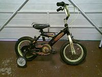

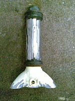
As soon as I got the cycle home I attacked it with my angle grinder leaving me with a perfect bearing with outer tube which would be welded to the chassis at a later date.
A real shame cutting up a child's cycle but as it was broken its gone to better use.
After stripping the bearing tube down I placed the old bike fork tube on to the caster bracket. After measuring up and getting exactly in the center and perfectly vertical I welded into place.

After welding I always finish off with a smear of filler around the weld to tidy things up. My welding is good but not perfect so a small smear of filler fills the odd pit.
I then sand down to a nice smooth finish.
Time to assemble the caster completely.
Now that's what I call a caster. Wheeling the caster around the floor holding onto the bearing pole the caster changes direction perfectly. Even the two wheels change direction and turn in opposite directions perfectly.
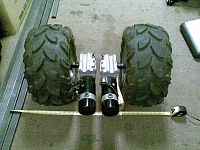
Now that I have all the wheels assembled I thought I would have a quick look at the size of the machine and the wheel layout.

I am working to a similar size of the Walker machine sizes with a wheel base of around 1 meter long and a tire tread width approx 70 cm wide.
If these sizes work perfectly for the walker machine then I will keep mine to a similar size.
And that’s it for this weeks build progress.
I plan to start assembling the chassis so that I have a rolling shell next week.
Next weeks progress will be posted on Sunday 13th so watch this space.
Thankyou for reading.
Well its finally time to start my winter project.
Hurray!! I have been looking forward to this years winter build.
Spending my evenings in my workshop hiding away from the wife.
Firstly please excuse my grammar and spelling during this build. I have never been that good at spelling and writing so what you read is as good as its going to get.
Ok now that I have got that off my chest.
Introduction
This year I am going to build a big Radio Controlled mower totally from scratch.
I plan to build the mower to the best of my ability and at the end of the project I hope to have a brand new machine. It will cost me a lot less than a brand new machine as any machine with a large cut size will cost thousands of pounds or dollars.
My first decision was the design for the machine. Which design should I build? A traditional garden tractor, a zero turn 4 wheeled mower a 3 wheel zero turn machine etc etc. Lots of options.
I ended falling in love with the Walker mower design using 2 large front wheels and a big rear caster type wheel.
What set this project going in the first place was the finding of 2 electric wheelchairs up for grabs in a local shop.
When I first got the chairs I didn’t know what to do with them at the time so I stripped them down for spares ready for my winter project.
The 2 wheelchairs are in good working order so they are ideal to power my lawn mower.
At this time I have not yet decided how to power the cutter deck. I have 3 choices but each with there own problems. 1. Power with 24 volt motors, 2 Power using hybrid technology. Electricity to power the motors and supplied by a petrol generator. 3 Finally a engine to power the blades.
I will discuss this later on in the build.
One thing that has been decided and that is the wheels are driven by 24 volt motors.
Part 1 Wheels.
I started buying various parts for this project. My first purchase was a set of 4 quad bike wheels found on ebay. On most 2wd quads the front wheels are a different size and are much taller than the rears. I wanted a really rough tread pattern for my tractor rather than a lawn saver type tyre.
These wheels have some serious tread on them as you can see. They will give me loads of grip on the grass hills I have to mow especially when the grass is wet.
Out of the 4 wheels I decided to use the 2 wider rear tires, they are less tall than the fronts making them easier on the motors when in use.
My second purchase was some bits of steel. I ordered some squares of 6mm plate and 4 lengths of box section for the chassis. Enough to get the project moving.
When I offered the motors up to the wheels some large hub adapters were required to fit them properly to the motors.
This was going to be a big task considering I don’t own a lathe.
The first job is to cut the 6mm plates to fit on to the wheels. After measuring up and finding the dead center point of the square plate I drilled a small hole in the center. I then cut the circles out of the 6mm plate.
This was very hard going. I don’t know if you have ever cut 6mm plate using a jigsaw? It took me ages to cut each one and it felt like I was wearing it away rather than cutting it. After a packet of blades and a lot of swearing the discs were finally cut.
I now needed to make the discs perfectly round. But I don’t have a lathe. No worries as I had already drilled the center hole, I fitted a nut and bolt and locked the disc on my pillar drill. Once the disc was spinning I gave the disc a good grind with my angle grinder.
Once they were perfectly round I measured out the wheel nut PCD’s and drilled the holes to fit the wheels.
Time to fit the discs to the wheels to check that they fit.
Spot on first time.
They are a perfect fit as well.
The next bit was to cut the hub spacer out of 50mm steel box section. After measuring up I cut the box section to size. I cut the steel box with a special steel cutting rage mitre saw as it cuts the steel perfectly square just like wood. Straight through in seconds.
I used part of the original hubs which were fitted to the original wheels on the chair as they have a keyway to lock them onto the motor shaft.
Time to weld the box section to the original hub. I used a threaded rod to clamp the box section to the hub.
Finally I now have two hubs ready to be welded to the wheel discs. This was a tricky job as the discs needed to be exactly in the center. If I welded them in the wrong place the wheels would turn like a old Laurel and Hardy pram.
I used my threaded rod again to clamp the discs to the newly made hubs.
After a lot of measuring and checking I welded the box section to the discs.
Time to find how good the new hubs were. I Put the hubs on my cordless drill and gave them a good spin.
Awesome job! When the discs were spinning there was very little movement and they were only a very small bit out of center. As the wheels only turn slowly you wouldn’t notice it. You might feel it if you were spinning them at 100mph.
The last job was to drill out the center of the discs as I have to fit a nut inside to fix the original hubs to the motor axles. The hole needs to be big enough to allow a socket to fit through to the inside hub.
Job done! Two completed extra long motor hubs.
Time to fit the motors to the wheels.
The new extra long wheel hubs are a perfect fit and it was time to give the new wheels a spin with the wheel chair motor. I set up the electrics on the bench and clamped the motor in the vice.
The wheels spin perfectly with very little movement.
Im very pleased with my first efforts building the wheel mounting hubs.
I put the wheels on the floor to see how wheels look with the motors.
They look great.
The tires are very wide and will make the machine look big and chunky.
The next task is to build the large rear caster wheel for the machine.
I decided to use 10 inch pneumatic wheels for the big caster.
Its very difficult trying to buy a ready made caster of this size as the caster needs to be as wide as possible for use on grass.
The first job is to make the 2 wheels ready for a big caster. When you buy wheels they have a off set to one side making them suitable for mounting on sack barrows, trolleys alike. So I brought 4 wheels so I could use 2 of the offset bearings on the other wheels with my caster.
Once all bolted together I used a threaded bar for the axle on the caster.
Once the wheels were ready and pumped up it was time to cut the steel for the caster.
I used my special rage bench saw which can easily cut steel plate up to 6mm thick.
Once cut up the steel is ready for drilling.
I clamped the plates together so that the holes were in the same place on both plates.
Now that the holes are drilled I can work out the correct angle for the sides of the caster. The caster turns when you change direction so swivel bearing needs to be at the back of the wheels.
Once lined up I welded the caster bracket together.
Now for the interesting bit. I had alittle trouble trying to find a suitable source for a swivel bearing to use with my caster. Most casters you buy are the flat type and are not really suitable to use on my machine.
Then all of the sudden I had a brain wave. What about a bicycle frame front fork bearing? I could cut the old frame up leaving me with the forks and frame tube.
So that’s exactly what I did. I trip down to the scrap merchants did the trick. In the skip was a child's broken bicycle. As all I needed was the steering so it didn’t matter what the bike was like. The scrap man fished it out of the skip and was happy to sell if to me for £5. Bargain.
As soon as I got the cycle home I attacked it with my angle grinder leaving me with a perfect bearing with outer tube which would be welded to the chassis at a later date.
A real shame cutting up a child's cycle but as it was broken its gone to better use.
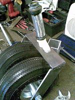
After stripping the bearing tube down I placed the old bike fork tube on to the caster bracket. After measuring up and getting exactly in the center and perfectly vertical I welded into place.
After welding I always finish off with a smear of filler around the weld to tidy things up. My welding is good but not perfect so a small smear of filler fills the odd pit.
I then sand down to a nice smooth finish.
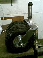
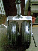
Time to assemble the caster completely.
Now that's what I call a caster. Wheeling the caster around the floor holding onto the bearing pole the caster changes direction perfectly. Even the two wheels change direction and turn in opposite directions perfectly.
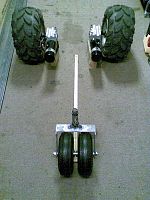
Now that I have all the wheels assembled I thought I would have a quick look at the size of the machine and the wheel layout.
I am working to a similar size of the Walker machine sizes with a wheel base of around 1 meter long and a tire tread width approx 70 cm wide.
If these sizes work perfectly for the walker machine then I will keep mine to a similar size.
And that’s it for this weeks build progress.
I plan to start assembling the chassis so that I have a rolling shell next week.
Next weeks progress will be posted on Sunday 13th so watch this space.
Thankyou for reading.


 11-10-2011, 11:14 AM
#4
Junior Member
Thread Starter
Join Date: Sep 2005
Location: Berkshire, UNITED KINGDOM
Posts: 19
Likes: 0
Received 0 Likes
on
0 Posts
Sorry chaps. This is as far as this topic goes as I have decided that this mower will be a ride on machine rather than radio controlled. Not much point carrying on with posting my progress in here if its not radio controlled.
For those who are interested. You can follow the machines progress in this forum here Link below:
http://kramerville.net/ubb/ubbthread...=5755#Post5755
For those who are interested. You can follow the machines progress in this forum here Link below:
http://kramerville.net/ubb/ubbthread...=5755#Post5755
