


How to DiY - VPX battery pack.
 08-08-2008, 09:24 PM
#1
Senior Member
Thread Starter

Join Date: Mar 2005
Location: Owasso,
OK
Posts: 1,307
Likes: 0
Received 0 Likes
on
0 Posts
So I put another VPX battery back together today and decided I take some pics for all those who had interest in making one.
If you are interested in making one of these there are a few things you'll need to start off.
-First, you'll need a battery charger that can handle LiFePo4 battery cells. Similar to the way LiPo's are charged but these cells are made with a completely different chemistry and charging them strait off a LiPo charger will damage them because of the differences in the nominal voltages, so I high recommend not using LiPo settings to charge with.
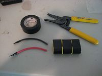
-You'll also need some of the basic tools of assembling battery packs: Soldering Iron and solder, GOOD wire, connectors, battery bar(s), wire shrink wrap, wire strippers, wire cutters, small flat head screwdriver, some needle nose pliers, and something to cover the finished battery pack. Because this involves disassembling the battery pack and rebuilding it, it is VERY helpful to have a Dremel with some fine sanding spools. GOOD wire is required because in order to get the most of what these batteries have to offer you need the least resistance possible and it is much easier to use good quality silicon insulted wire. Expensive yes, but it's worth it. I used 13 gauge, plenty to allow lots of current which is what you want because you'll rely on the current to drive the power rather than the higher voltage.
-Lastly you'll need the VPX battery to disassemble.
Got the tools (and the charger)?
Step 1
Get you're tools all set to the side and clean off your work space.
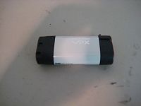
Place the VPX pack in your work space and admire it before you destroy the nice looking covering and throw it in the trash
Step 2
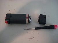
Remove the which stick on label. You'll see 2 clip tabs on the end with the exposed terminals. Take your small flathead screwdriver and unclip each side. These tabs are kinda tough so careful not to jab yourself in the hand or finger while trying to get the end cap off. Also remember that those cells inside are about $8-10 a pop and I doubt you want to damage them. Once you manage to get the clips off the end cap slides off.
Step 3
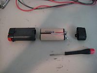
The pack isn't attached internally, so slide the 2 cells out along with the attached power tabs.
Step 4
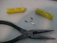
Seperate the power tabs from the cells to give yourself some room to clip the wire individually. DO NOT CLIP MORE THAN 1 AT A TIME. These batteries can discharge more current than 20C LiPo's. You'll most likely kill the cells if you short them, not to mention risk giving yourself a nasty burn and making a nice wire stripping hole in the pliers you just shorted the battery out with.

Step 5
Clip off each wire holding the terminals on the cells individually. Throw away the terminals.

Step 6
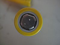
The factory battery tabs are spot welded on, so trying to desolder them isn't going to do anything except waste your time. Flex them a bit to separate the cells. Use your needle nose pliers to flex/twist the tabs off the cells. Don't try and grab the tab and "roll" the tab around the pliers to pull them off, you'll end up bending the battery end where the tab is held on. I found it easiest to flex/twist the tabs (imagine them as a screw going into the end of the battery) holding the pliers sideways in relation to the battery. If you break off the tabs and there is still a little bit connected where the weld is, we'll get to that.
Some pics of cell ends of what to expect:

Step 7
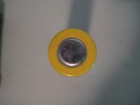
You'll now want to clean up the ends using a Dremel tool with a fine sanding spool. My wire brushes were not able to take off the remainder of the tabs you see in the previous pic but the sanding spool did perfect with a careful hand. Cleaning up the ends helps with the soldering process so make them reasonably smooth. One of my finished ends after using the sanding spool then a fine wire brush with a Dremel:
Step 8
Time to attach the battery bar so turn on the soldering iron. My first pack I used a standard Sub-C battery bar. It was a little big, but fit fine because there is a large button area on each end of the cells to solder onto. For this pack I used a 2/3 A battery bar, which fit better.

Step 9
Do a better soldering job than I did. I ended up redoing that messed up end. Be sure the solder flows onto each battery end. If it doesn't flow, then if it does stick, it wont stick for long (what you just created is a cold solder joint). These cells have been very forgiving to me when soldering them. I used electrical tape to hold the 2 cell together while soldering them, also makes things easier.
Step 10
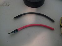
Cut your desired length of wire. The longer the wire, the more resistance you're adding, so don't use more than you reasonably need.
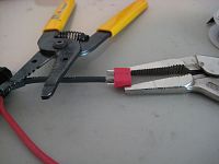
IMPORTANT: See how I taped up one end of each wire? This keeps the ends from shorting out while soldering the wires onto the cells.
Strip a small section of insulation off each wire in preparation for soldering to the cell ends.
Step 11
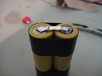
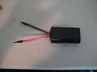
Solder the negative wire to the negative terminal and the positive wire to the positive terminal. If you haven't figured it out already, these cells are arranged in series.
I soldered the wires so that each one was pointing toward the opposite cell. That way I could bend the wires out away from the cells in the center between the cells (see picture). Cover your pack with whatever you are going to use. I would like to have used large heat shrink tubing but no place near me carried the right size, not even the local hobby shop, so I used electrical tape.
Step 12
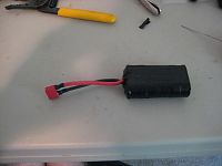
Next step is to attach your own terminals. I ALWAYS used female sided connectors for battery terminals, helps keep the battery from shorting out on lose things like belt buckles, tools, your RING if you wear one (could leave a BAD burn). I also use the best terminals out there: Dean's Ulta T-plugs: secure connecting, long lasting, insulating composite has high melting temperature to endure soldering (see Deans Knock-off threat for more stuff on this and like products). Don't for get to add your heat shrink before you solder the connector on. Not required but it helps to have some vice grips to hold the connector while you solder to it. Note that on the ends of deans connectors there is a "+" and "-" to indicate which wire goes where. Only remove the electrical tape from one wire while soldering.

Solder that wire onto the connector. Wait for it to cool then slide the shrink wrap over the connection and use a heat source to shrink it. Again, solder must "flow" onto the end so as to avoid a cold solder joint. After one wire has been soldered and shrink wrapped, remove the electrical tape from the other wire and solder it to the connector in the same way you soldered the first one, remembering to add your shrink wrap wrap before you solder. Shrink wrap the finished connection.
Step 13
You're done! Charge up and go!
If you are interested in making one of these there are a few things you'll need to start off.
-First, you'll need a battery charger that can handle LiFePo4 battery cells. Similar to the way LiPo's are charged but these cells are made with a completely different chemistry and charging them strait off a LiPo charger will damage them because of the differences in the nominal voltages, so I high recommend not using LiPo settings to charge with.
-You'll also need some of the basic tools of assembling battery packs: Soldering Iron and solder, GOOD wire, connectors, battery bar(s), wire shrink wrap, wire strippers, wire cutters, small flat head screwdriver, some needle nose pliers, and something to cover the finished battery pack. Because this involves disassembling the battery pack and rebuilding it, it is VERY helpful to have a Dremel with some fine sanding spools. GOOD wire is required because in order to get the most of what these batteries have to offer you need the least resistance possible and it is much easier to use good quality silicon insulted wire. Expensive yes, but it's worth it. I used 13 gauge, plenty to allow lots of current which is what you want because you'll rely on the current to drive the power rather than the higher voltage.
-Lastly you'll need the VPX battery to disassemble.
Got the tools (and the charger)?
Step 1
Get you're tools all set to the side and clean off your work space.
Place the VPX pack in your work space and admire it before you destroy the nice looking covering and throw it in the trash
Step 2
Remove the which stick on label. You'll see 2 clip tabs on the end with the exposed terminals. Take your small flathead screwdriver and unclip each side. These tabs are kinda tough so careful not to jab yourself in the hand or finger while trying to get the end cap off. Also remember that those cells inside are about $8-10 a pop and I doubt you want to damage them. Once you manage to get the clips off the end cap slides off.
Step 3
The pack isn't attached internally, so slide the 2 cells out along with the attached power tabs.
Step 4
Seperate the power tabs from the cells to give yourself some room to clip the wire individually. DO NOT CLIP MORE THAN 1 AT A TIME. These batteries can discharge more current than 20C LiPo's. You'll most likely kill the cells if you short them, not to mention risk giving yourself a nasty burn and making a nice wire stripping hole in the pliers you just shorted the battery out with.
Step 5
Clip off each wire holding the terminals on the cells individually. Throw away the terminals.
Step 6
The factory battery tabs are spot welded on, so trying to desolder them isn't going to do anything except waste your time. Flex them a bit to separate the cells. Use your needle nose pliers to flex/twist the tabs off the cells. Don't try and grab the tab and "roll" the tab around the pliers to pull them off, you'll end up bending the battery end where the tab is held on. I found it easiest to flex/twist the tabs (imagine them as a screw going into the end of the battery) holding the pliers sideways in relation to the battery. If you break off the tabs and there is still a little bit connected where the weld is, we'll get to that.
Some pics of cell ends of what to expect:
Step 7
You'll now want to clean up the ends using a Dremel tool with a fine sanding spool. My wire brushes were not able to take off the remainder of the tabs you see in the previous pic but the sanding spool did perfect with a careful hand. Cleaning up the ends helps with the soldering process so make them reasonably smooth. One of my finished ends after using the sanding spool then a fine wire brush with a Dremel:
Step 8
Time to attach the battery bar so turn on the soldering iron. My first pack I used a standard Sub-C battery bar. It was a little big, but fit fine because there is a large button area on each end of the cells to solder onto. For this pack I used a 2/3 A battery bar, which fit better.
Step 9
Do a better soldering job than I did. I ended up redoing that messed up end. Be sure the solder flows onto each battery end. If it doesn't flow, then if it does stick, it wont stick for long (what you just created is a cold solder joint). These cells have been very forgiving to me when soldering them. I used electrical tape to hold the 2 cell together while soldering them, also makes things easier.
Step 10
Cut your desired length of wire. The longer the wire, the more resistance you're adding, so don't use more than you reasonably need.
IMPORTANT: See how I taped up one end of each wire? This keeps the ends from shorting out while soldering the wires onto the cells.
Strip a small section of insulation off each wire in preparation for soldering to the cell ends.
Step 11
Solder the negative wire to the negative terminal and the positive wire to the positive terminal. If you haven't figured it out already, these cells are arranged in series.
I soldered the wires so that each one was pointing toward the opposite cell. That way I could bend the wires out away from the cells in the center between the cells (see picture). Cover your pack with whatever you are going to use. I would like to have used large heat shrink tubing but no place near me carried the right size, not even the local hobby shop, so I used electrical tape.
Step 12
Next step is to attach your own terminals. I ALWAYS used female sided connectors for battery terminals, helps keep the battery from shorting out on lose things like belt buckles, tools, your RING if you wear one (could leave a BAD burn). I also use the best terminals out there: Dean's Ulta T-plugs: secure connecting, long lasting, insulating composite has high melting temperature to endure soldering (see Deans Knock-off threat for more stuff on this and like products). Don't for get to add your heat shrink before you solder the connector on. Not required but it helps to have some vice grips to hold the connector while you solder to it. Note that on the ends of deans connectors there is a "+" and "-" to indicate which wire goes where. Only remove the electrical tape from one wire while soldering.
Solder that wire onto the connector. Wait for it to cool then slide the shrink wrap over the connection and use a heat source to shrink it. Again, solder must "flow" onto the end so as to avoid a cold solder joint. After one wire has been soldered and shrink wrapped, remove the electrical tape from the other wire and solder it to the connector in the same way you soldered the first one, remembering to add your shrink wrap wrap before you solder. Shrink wrap the finished connection.
Step 13
You're done! Charge up and go!
 08-08-2008, 09:54 PM
#2
Senior Member
My Feedback: (1)

Join Date: Dec 2007
Location: San Luis Obispo,
CA
Posts: 1,324
Likes: 0
Received 0 Likes
on
0 Posts
dude your the MAN!!!!!!!!!!!!!!!!!!!
this is so informational!!
i love you haha kidding just thanks a ton now ill think ill do this
hope this is a sticky too
this is so informational!!
i love you
haha kidding just thanks a ton now ill think ill do this hope this is a sticky too
 11-30-2008, 09:59 PM
#4
Junior Member
Join Date: Jan 2008
Location: BFE,
WV
Posts: 12
Likes: 0
Received 0 Likes
on
0 Posts
thanks for the write up, i just bought a couple of these batteries and when i pulled it apart i was wondering what wires needed to stay. i like the clean cell to start with. i am ready to tackle this battery now. again thanks.
 12-02-2008, 06:42 AM
#6
Senior Member

Join Date: Jul 2004
Location: Jakarta, INDONESIA
Posts: 180
Likes: 0
Received 0 Likes
on
0 Posts
12-02-2008, 10:33 PM
#8
Senior Member
Thread Starter
Join Date: Mar 2005
Location: Owasso,
OK
Posts: 1,307
Likes: 0
Received 0 Likes
on
0 Posts
It'll be a while before I end up making another 2 cell pack. My latest packs have been using the much large M1 cells or 2300mah cells in a 4s configuration for my brushless crt.5. They are a bit harder to work with and take much longer to make. Dunno if I'll get around to doing a write up on them.
12-02-2008, 11:17 PM
#9


Join Date: Mar 2006
Location: U.P.,
MI
Posts: 8,048
Likes: 0
Received 0 Likes
on
0 Posts
ORIGINAL: Papa Jay
great write up.
Here is the wiring for balance tabs
http://scriptasylum.com/rc_speed/_lipo.html
great write up.
Here is the wiring for balance tabs
http://scriptasylum.com/rc_speed/_lipo.html
Great link man! Thanks for finding it for us.
Kevin
 12-30-2008, 11:40 AM
#11
Senior Member
My Feedback: (2)

Join Date: Jun 2008
Location: Panama City Beach,
FL
Posts: 886
Likes: 0
Received 0 Likes
on
0 Posts
awesome post! i like the safety warnings 
heres a few tips i think you overlooked that will make the job as good as pro...
tin everything! a properly tinned tip, wire, battery surface, bus bar, and/or connector makes all the difference! if everything already has solder on it, you will spend only a fraction of the time applying heat to your surfaces. once you try it, you'll understand. the days of cold solder joints and melted connectors are over!
having trouble getting old solder to flow? can't get the solder to stick? use flux! a small container of flux is only a few bucks and pays for itself the first time you avoid damage to a component. flux remover is always nice to clean up the gooey mess, but not required.
make sure your tip is clean and HOT! a small damp sponge slotted in the middle works great for removing excess solder and melted garbage on your iron. the proper size and temperature tip ensures that you spend the least amount of time possible applying heat to your surfaces.
12-31-2008, 02:07 PM
#13
Senior Member

Join Date: Jan 2007
Location: vacaville,
CA
Posts: 1,968
Likes: 0
Received 0 Likes
on
0 Posts
12-31-2008, 05:34 PM
#19
Senior Member
Thread Starter
Join Date: Mar 2005
Location: Owasso,
OK
Posts: 1,307
Likes: 0
Received 0 Likes
on
0 Posts
I'm using them in my brushless Detta and brushless CRT.5, though the CRT.5 is a 4S 2300 pack. Biggest obstacle is finding a way to fit or mount the battery and have a charger that can charge them.
Same constant current/constant voltage charge cycle as other lithiums but the cut off and charge voltages are much lower. I think my FMA charger is set for 3.65V as the charging voltage and my Onyx is 3.6V.
The vendettas have enough room on the wide chassis to fit a side by side pack with room to spare lengthwise.
For any system I would use an ESC that has a programable cut-off voltage. I use 2.0V per cell as my cut off voltage.
12-31-2008, 08:20 PM
#20
Senior Member

Join Date: Jun 2007
Location: Brandon, SD
Posts: 1,684
Likes: 0
Received 0 Likes
on
0 Posts
Nice! Hopefully a123 stuff will become more popular now. Maybe the price will go down and a123 will reconize the RC industry and make lipo type packs.
The one thing missing is the reason to use a123 packs. The durability, the discharge rates, and the all around goodness.
The one thing missing is the reason to use a123 packs. The durability, the discharge rates, and the all around goodness.
02-04-2009, 04:49 PM
#22
Senior Member
Join Date: Jun 2007
Location: Brandon, SD
Posts: 1,684
Likes: 0
Received 0 Likes
on
0 Posts
http://www.scriptasylum.com/rc_speed/_lipo.html
You might neet to click on lipo pack wiring on the left. Click "show balance connecters". Making an a123 pack is just like making a lipo pack, the cells are just different shapes. Of the four wires, one goes to the positive lead, one goes to the first cell's negatoive lead that will read 3.3v, one will go to the negative on the second that will read 6.6v, and the last one goes to the last cell's negative lead and will read 9.9v. It's pretty dang simple... Just make sure you're using the right balancer. Some balancers use a different way to wire the balance leads, so make sure this is right...
You might neet to click on lipo pack wiring on the left. Click "show balance connecters". Making an a123 pack is just like making a lipo pack, the cells are just different shapes. Of the four wires, one goes to the positive lead, one goes to the first cell's negatoive lead that will read 3.3v, one will go to the negative on the second that will read 6.6v, and the last one goes to the last cell's negative lead and will read 9.9v. It's pretty dang simple... Just make sure you're using the right balancer. Some balancers use a different way to wire the balance leads, so make sure this is right...
