Finished Leading Edge Flap (LEF) install today. I found my LEF linkage did not work correctly if installed per instructions in the manual. Details are below.
First, after my understanding of how the LEF linkage worked I highly encourage everyone to accomplish the modification to
beef up the servo mount per Anton's post #710 in the "It's Coming…F-16 ARF PRO" thread. Photo in my post #256 above. The reason for this as I see it is because all of the lifting force on the LEF during flight is transmitted through the LEF hinges, carbon control horn, into the servo arm, and into the servo body. This force is trying to literally pull the servo down and out of the mounts in the wing. During high G turns at high speed this force has got to be strong. I have no idea how much but Im sure its a lot.
The only thing holding the LEF in position are the wood screws. In a normal servo installation the force is perpendicular to the screws but here it is trying to pull the screws out of the holes. This is why Anton says put wood under the existing mounts and use longer screws.
I have seen a LEF blow up failure in the full scale F-16. It is barely controllable and then only because of the fly-by-wire flight control system. It would not in my opinion be controllable in the RC model. I do not know if the LEF would fully blow up but at the hinge stop it is several degrees leading edge up. Therefore I encourage all flying this jet to do the mod to the LEF servo mounts.
I added shaped plywood and hysol under each servo mounting tab and also on the inboard and outboard sides of the servo well just to help bond the two wing skins together around the stress area.
Mod Alert!
When installing the LEF servos I prepared the servo arm as per instruction manual and drilled the hole for the bearing stack at 10mm from servo spline center.
When I installed the servo and checked the LEF movement I found that the down travel was restricted to about 1/2 of full travel. LEF full down is where the carbon control arm is touching the top wing skin and can move no further. The reason was that the bearing stack was hitting the end of the bearing slot and movement stopped.
My fix was to move the hole for the bearing stack on the servo arm from 10mm to 13mm. This allowed full control arm travel and the bearing stack does not contact either end of the slot.


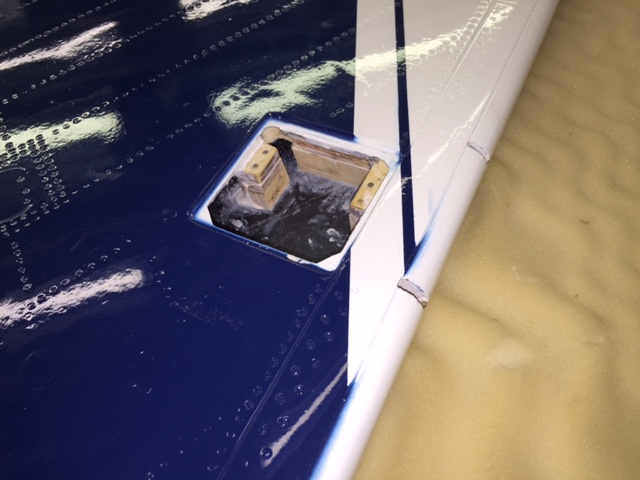
1st photo: Shows left wing LEF at full down position with carbon control arm touching the upper wing skin. (Aft is at top of photo and left wing is upside down in photo) A close look will show the bearing stack is not contacting the aft part of the slot with the LEF full down. A closer look will show the first bearing stack hole at 10mm just behind the bearings. You can tell from this photo that if the bearings were at 10mm the stack would not fit into the slot at the LEF full down position.
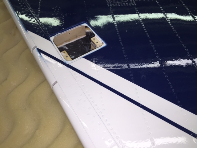
2nd photo: Shows left wing LEF in mid position with servo arm parallel to servo body. This position is where the bearing stack is furtherest forward in the slot. Note it is slightly forward of the center of the slot but not contacting the forward end of the slot. You can also see the first hole in the servo arm at 10mm which would put the bearing stack too far aft.
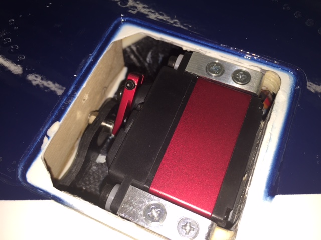
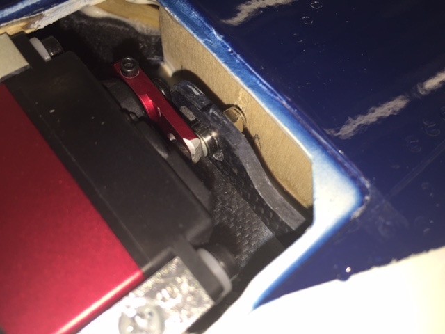
3rd and 4th photos: Same for right wing.
Also I had to use two washers under the bearing stack to get both bearings into the slot. The supplied 3mm bolt was not long enough to stack all the washers and bearings and have the elastic safety nut fully engage the threads. I replaced the bolt with a 3mm x 16mm socket head bolt.
Lastly I will replace both servo arms before flying. I do not have confidence that the new holes at 13mm have enough metal around them for use in this high stress application. I just wish I had figured all this out before I cut them off.
Recommendation: Use the suggested 10mm distance as a starting point and measure your set up before drilling and cutting off the servo arm. With the variances in servos, manufacture of the wing, LEF, mounts, control arm installation, and etc, I recommend a hole that places the bearing stack 1-2mm forward of the center of the carbon control arm slot. This will allow full up and down travel of the LEF without the bearing stack hitting either end of the slot and restricting the travel.
Hope this helps.
Gary