c) Mounting servos, linkages and the stab.
I decided to use the Futaba S.BUS2 Brushless servos (Made in Tawain by the way) that is recommended for Galactika, although all the recommended servos cost a fortune.
Elevator:
BLS173SV x 2 ("mini" servo)
Weight 28 gram (0.99 oz) - total weight for both 56 grams (1.975 oz)
6.0 - 7.4 volt
Speed 0.11 sec/60 deg at 6.6 volt, 0.10 at 7.4 volt
Torque 6.8 kgf * cm at 6.6 volt, 7.6 kgf * cm at 7.4 volt
Seize 33x15x27.1 mm (1.30x0.59x1.07 in)
Aileron:
BLS174SV x 2 ("low profile" servo with 6 degree slope on top deck)
Weight 53 gram (1.87 oz) - total weight for both 106 grams (3.739 oz)
6.0 - 7.4 volt
Speed 0.10 sec/60 deg at 6.6 volt, 0.09 at 7.4 volt
Torque 8.8 kgf * cm at 6.6 volt, 9.6 kgf * cm at 7.4 volt
Seize 47.5x27x25.4 mm (1.87x1.06x1.0 in)
Rudder:
BLS171SV x 2 ("standard" servo seize/weight)
Weight 48 gram (1.69 oz)
6.0 - 7.4 volt
Speed 0.11 sec/60 deg at 6.6 volt, 0.10 at 7.4 volt
Torque 10.6 kgf * cm at 6.6 volt, 11.8 kgf * cm at 7.4 volt
Seize 47.5x27x25.4 mm (1.87x1.06x1.0 in)
Mounting
elevator servos:
To drop in the BLS173SV elevator servos in the stabs the plywood mounting plate hole had to be slightly carved out to get it slightly longer. The servos was mounted with both the rubber grommets and the metal insert in the grommet and fastened with 2.2 x 11 mm hex servoscrews. I brushed a layer of epoxy top and underside on the plywood mounting to get little tighter fit for the screws and prevent breakup of plywood when the screws was tightened.
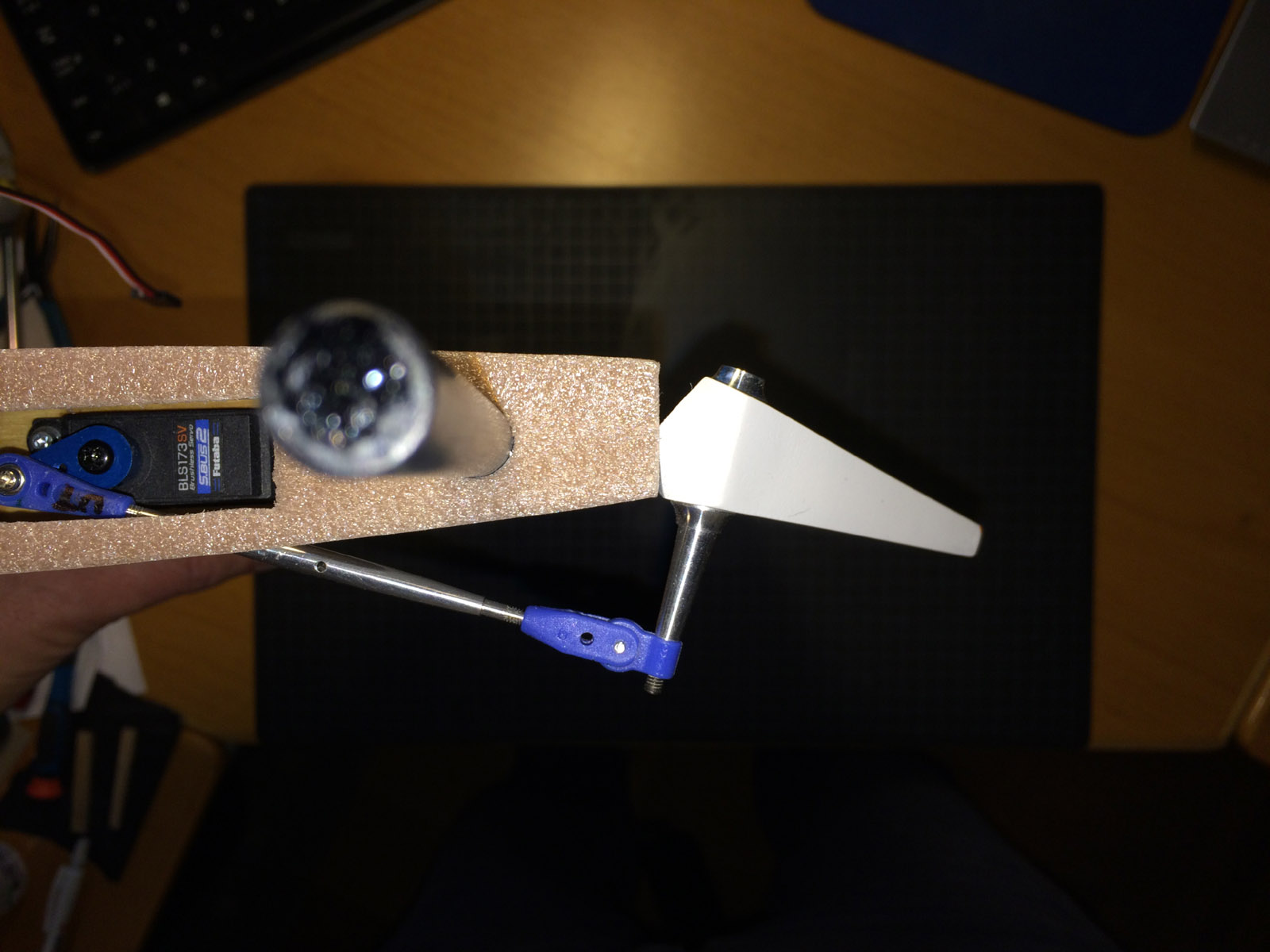
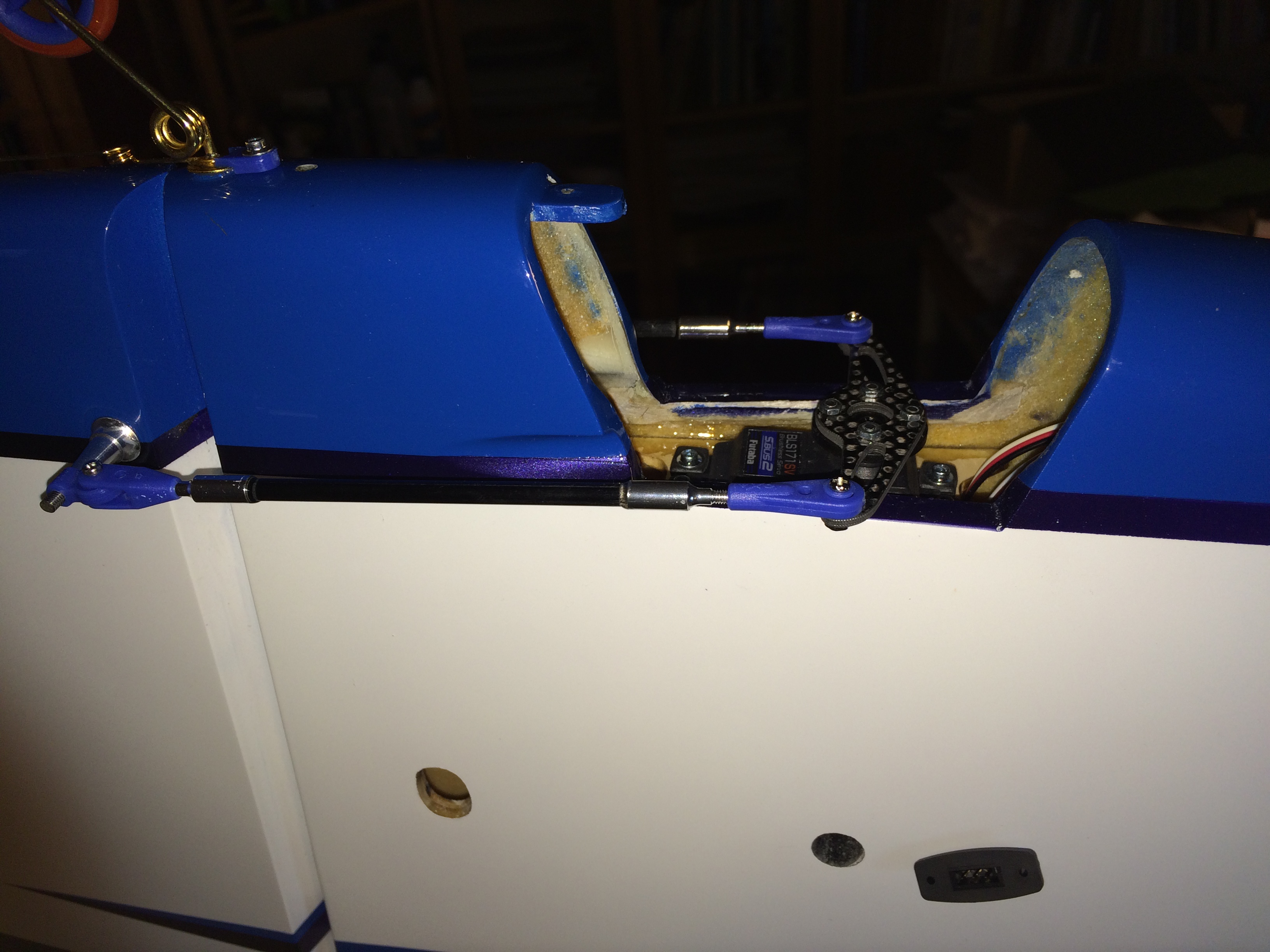
Servo arm I selected to use is the same as I use in my Sebart MythoS Pro, it is 15 mm metal servo arm from Robbe (item no 8512, discontinued). Ball bearing link is attached to the servo arm at second hole that is 8.5 mm out from center servo screw.
Elevator horn (metal), links (plastic with ball bearing in one end) and metal rod (with threads so one can twist the rod to adjust the length) was supplied as Oxai accessories and fitted nicely.
The main work was to cut out the holes on underside stabs where the rod goes through to the horns. Also the plastic cover over that hole was quite some work to cut out, trim and sand to perfect fit and last glue with thin CA.
Last I added a label on each stab at the plastic cover with the servo ID and Channel used and that way it is easier if the servo (althoug unlikely) needs to be adjusted later with Futaba S. Link PC Programmer application. I did this labeling at all servos in the plane.
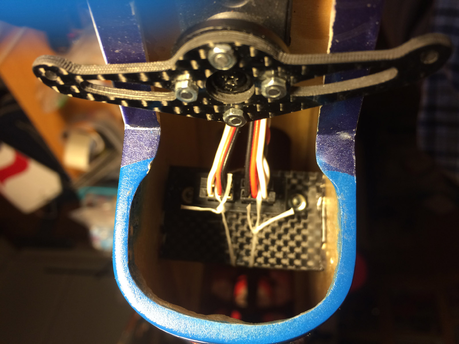
The elevator servos is connected to a 4 socket S.BUS hub in the tail, and I use fixed connectors glued on side of fuselage to quick and easy connect the elevator servos if stabs are removed/attached at transportation. It is Robbe fixed connector (item no F1639, discontinued) I use.
The servo connectors in the S.BUS hub is secured with dental floss.
This is a good thing to save some weight in general and specifically in tail.
Although I have not done it yet, one can shorten the servo cables as much as possible to save some more weight.
Elevator, rudder and fixed connector leads can be shortened considerably if one want.
Throwns on elevator was intitially set for normal flying to 8.0 degrees up and 8.5 down, and max allowable throws is around 17 degrees, I set max up to 17.0 and max down to 17.5 degrees.
The elevators are pre hinged from factory with minimal gap (about 0.1 mm) so this was nicely done at factory.
Stabs was an easy install, two carbon tubes go through fuselage and in each carbon tube ends it is hardwood pieces so M2.5 hex screws is going through that and hold the stab in place. All fitted perfectly from factory.
The white plastic covers over the hole for the elevator rods was more work with then expected.
First I had to trim the outer edges leaving about 2 mm edge and then open the hole for the rod to go through to the elevator horn. That was a slow job since the plastic seemed to be rather fragile and I wanted no cracks. Finally it was finished and they where glued to the stabs with thin CA letting the capillary force do the job.
This work took much longer then expected.
In the tail it is also a hole in front of tail wheel for adjusting the stab incidence with a 120 mm or longer 2.5 mm hex wrench. Whole stab is adjusted as one unit so You can not adjust incidence on each stab individually.
Mounting
aileron servos:
The BLS174SV aileron servos did fit without carving in the wing but needed slightly rased mounting plate to get perfectly aligned with wing skin. 0,5 mm plywood spacer was glued and then the servo was aligned with the surface. 2.2 x 11 mm hex servo screws was used also here.
Servo lead length has enough length and about 150 mm (5.9 in) remained outside wing root to connect to fuselage fixed connector (same Robbe fixed connector and lead type as used for elevator guick connector).
Servo arm I use is the plastic arm that was shipped with the BLS174SV servo, and I cut away plastic material on the servo arm that was not needed. The servo arm mounting shaft is wider then on mini and standard servos so the metal arm I planned to use did not fit, wrong spline. It had to be the plastic arm that came with the servo. It is "F4" spline 25 tooth on this servo.
The ballbearing link is mounted 17 mm out in 3rd hole on servo arm and this gives max physical allowed throws on aileron.
Throws I set initially was 8.0 degrees up/down and max was 17.0 degrees up/down.
The metal aileron horns supplied by Oxai was screwed to aileron with 2.2 x 8 mm hex servoscrews, the aileron had already plywood under the aileron skin for the screws fastening.
Aileron horn height up to the ball link mounting hole is 27 mm.
Ailerons are pre hinged from factory with minimal gap (about 0.1-0.2 mm) so this was nicely done at factory.
Mounting
rudder servo:
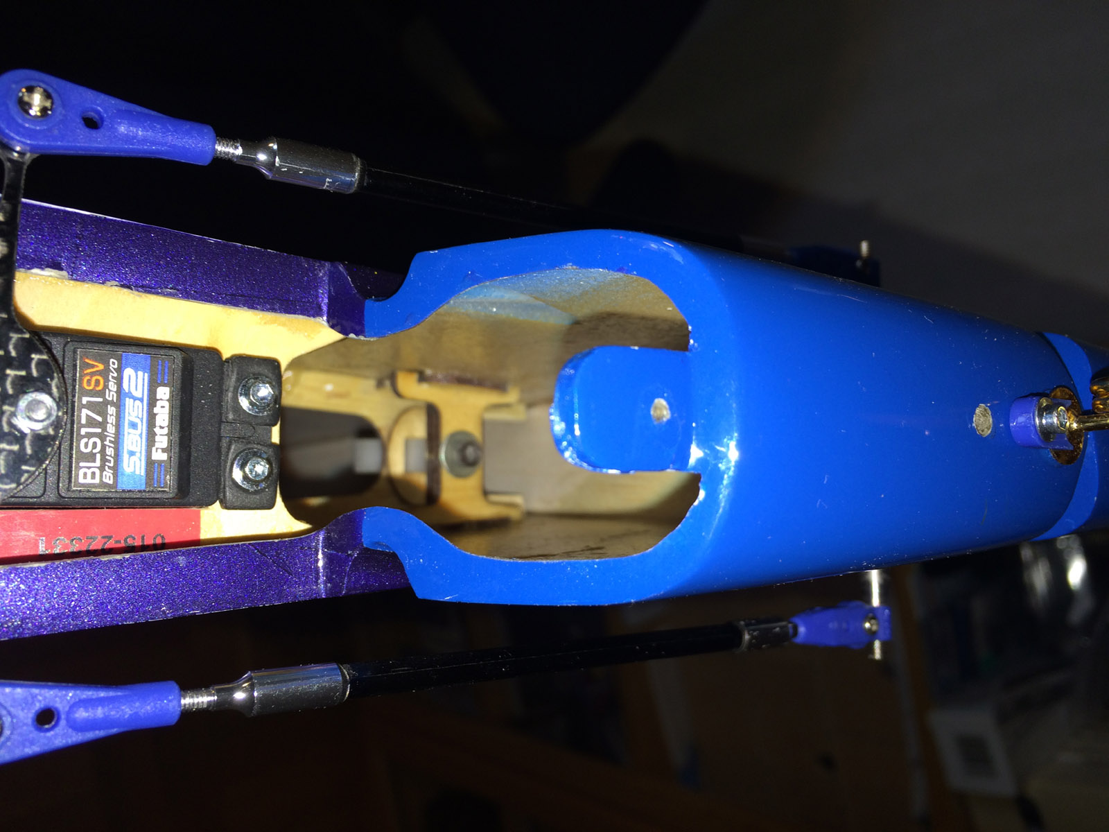
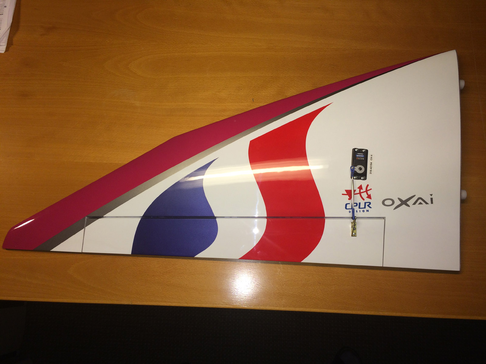
The BLS171SV ruder servo fitted directly in the tail plywood mounting plate supplied by Oxai.
The plate is glued in the tail underside opening where it is a hatch for rudder servo.
Oxai supply in the accessories bag also a long carbon servo arm predrilled that is screwed to the standard round servo arm that ships with BLS171SV that gives proper throws.
Ball bearing links and carbon rod (that is glued to metal threaded ends) is also supplied and all fit nicely.
It is rather crowded under the hatch where the rudder servo is mounted when all is in place (carbon servo arm, rods, S.BUS hub where 4 servo connectors meet - one that comes from front S.BUS hub, two for the elevator servos and one for rudder).
Throws on rudder has been set for normal flying to 16.5 degrees and for high rate (spin / stall turn / snap) to 36.0 degrees.
The tail hatch is a little tricky to mount and unmount but with some coaxing it works.
The hatch is fastened with a 2.2 x 11 mm hex servo screw and in front it is held in place by a flange and I mounted some Secraft padding material there to prevent rattle.
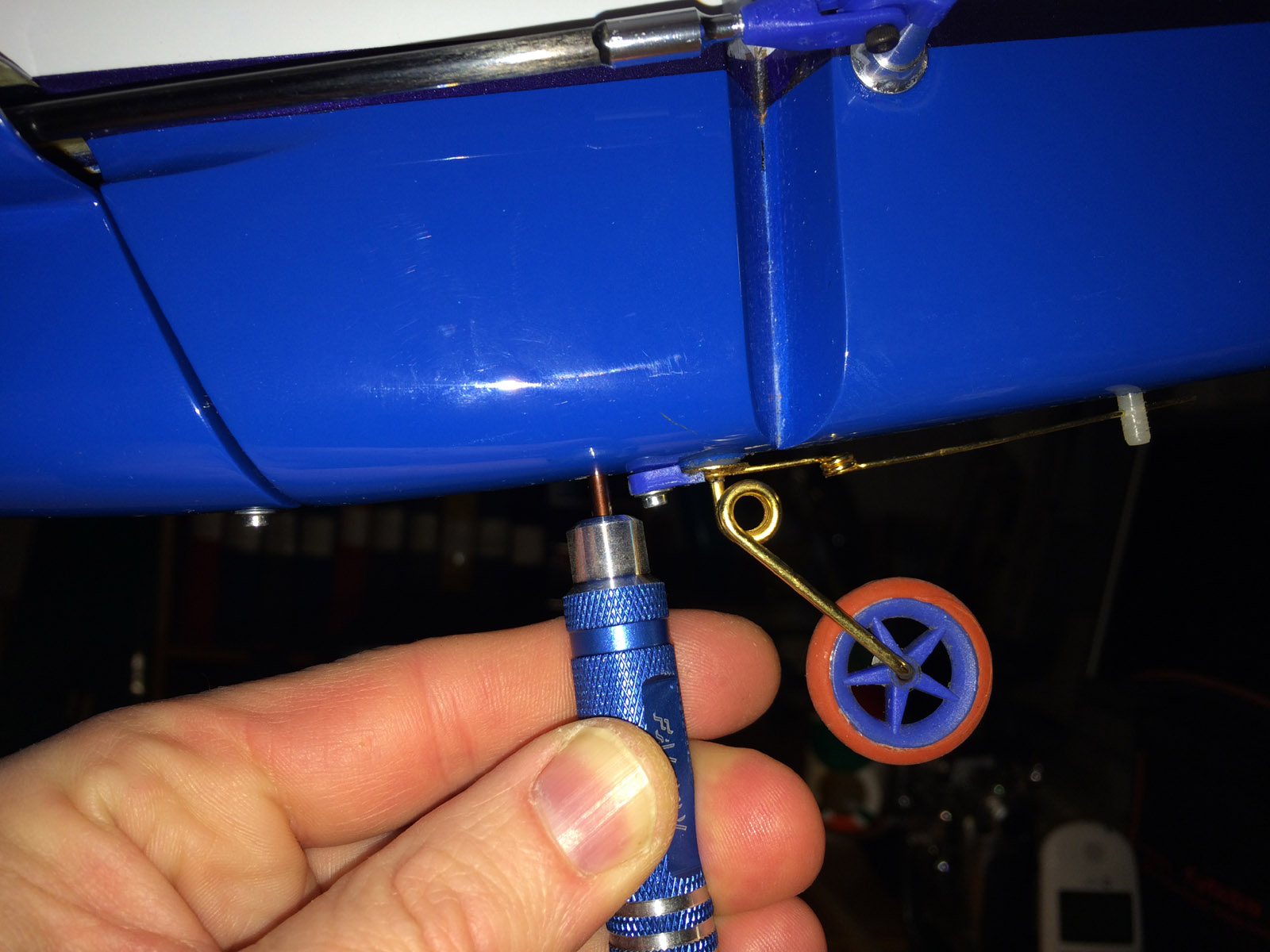
When all this was done the tailwheel was mounted using all parts supplied by Oaxi.
The tail wheel wire and mounting is OK and seems to be able to cope with also little harder encounter with the ground. There is a thinner pianowire extending to rear that is fastened in a nylon rod in rudder that follow rudder movements making stearing of tailwheel work nicely.
The tailwheel itself is very narrow and the rubber on the rim is thin and on one landing I saw the tyre fly off the rim, and I had to glue the tyre to rim with CA to be sure it stay in place.
The work mounting the elevators, ailerons and rudder servos, glueing the mounting plate etc and mounting the tail wheel etc took 4 evenings for me, more time then I expected (as usual).
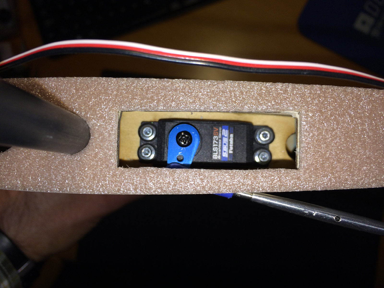
One elevator servo mounted. 2 mm soft material is mounted from factory on stab root to get a tight and soft contact with fuselage side when stab is mounted.


Slots for elevator rods had to be cut out. One stab ready, carbon tubes has been mounted and the two mounting screws has been tightened.
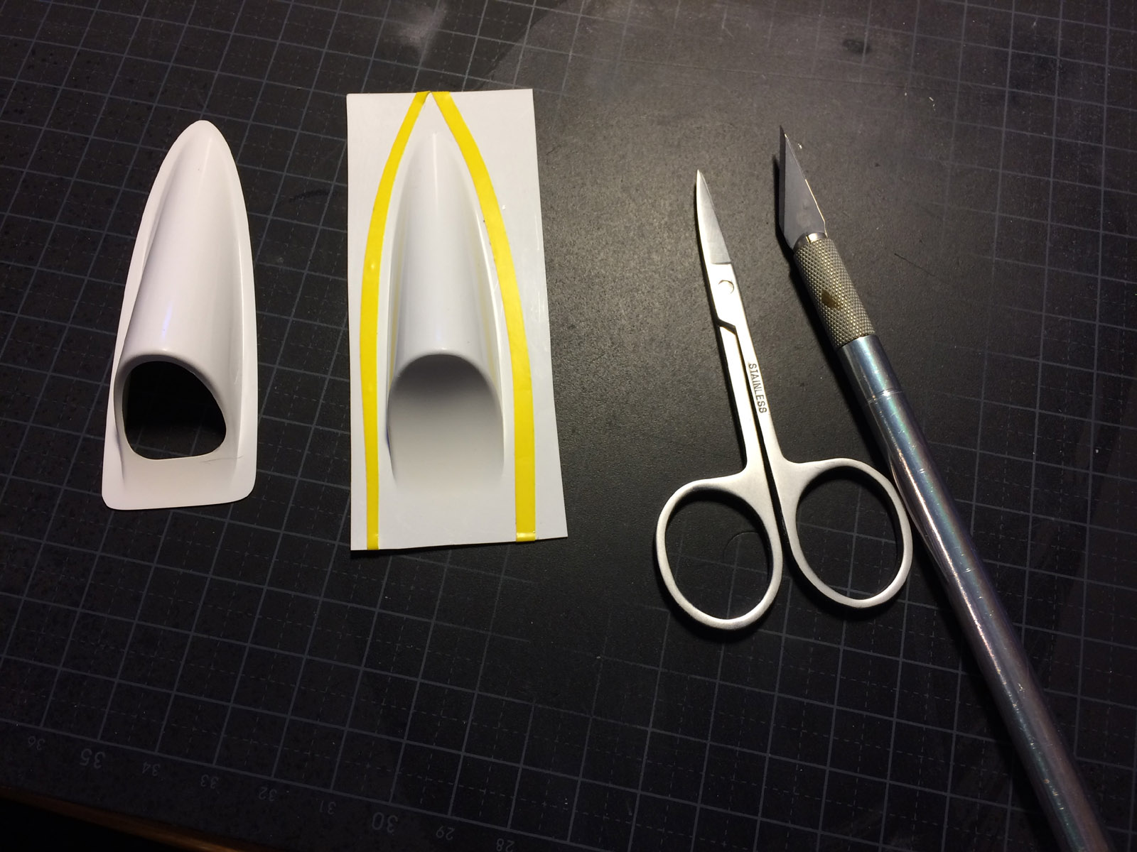
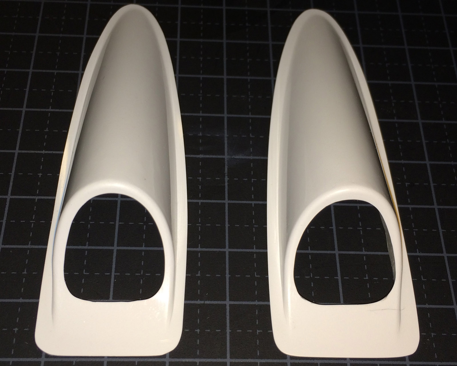

The white plastic covers had to be trimmed and mounted over the holes in the stabs.
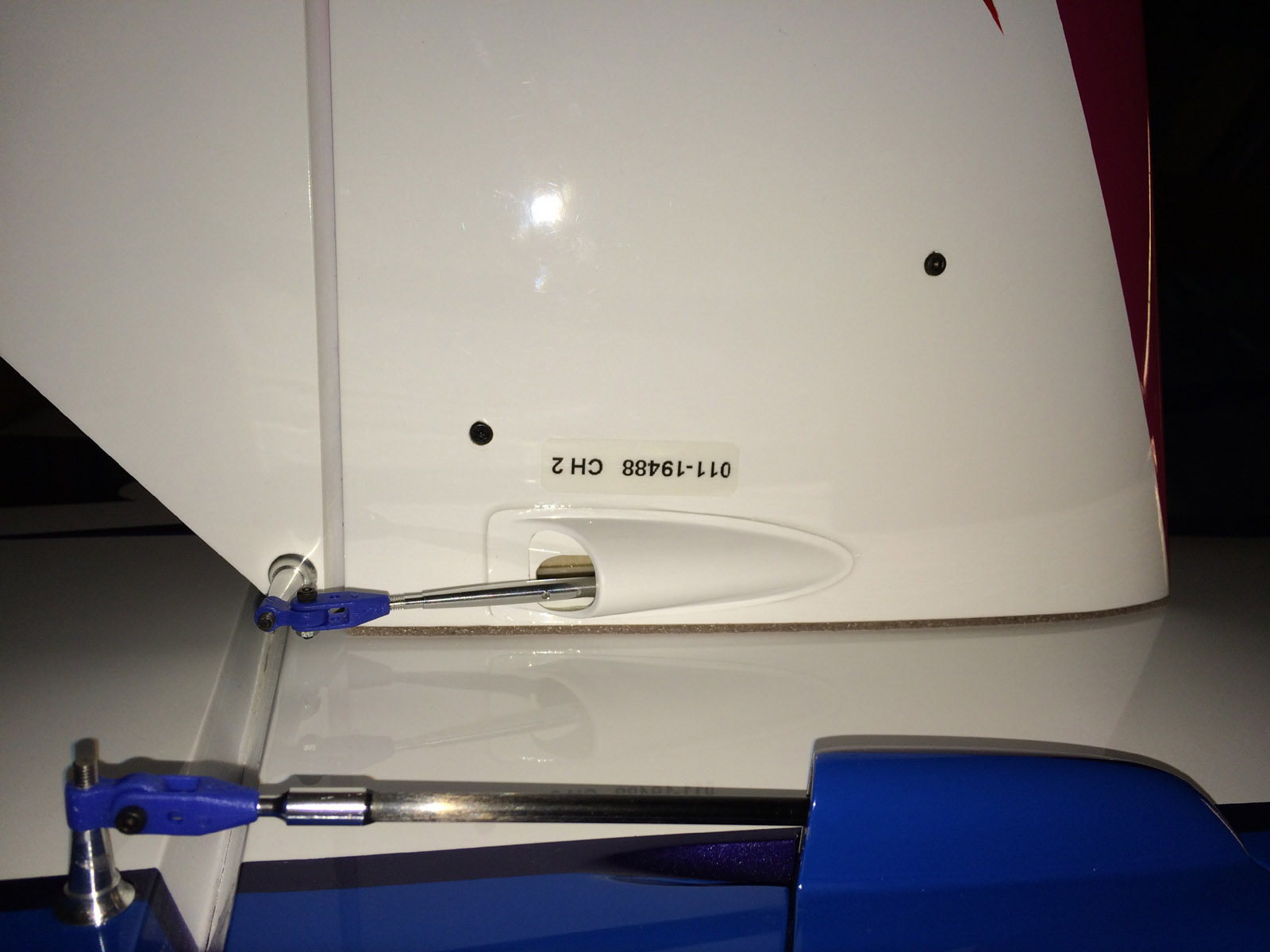
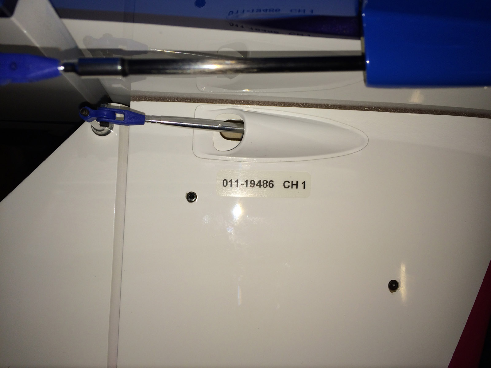
The cover has been glued to the stabs. Notice the labels with S.BUS servo ID number.


Stabs is easily unmounted/mounted. Quick fixed servo connector is mounted in fuselage.


Servo max physical throws that is possible (about 17-18 degrees up/down).

S.BUS 4 way connector in tail and the single servo lead to the tail (trough a paper made tunnel). Adjustment screw for stab incidence adjustment in the tail.


Servos mounted in the wings.


Aileron servo linkages. Wing servo connector in fuselage for Quick mounting and unmounting of the wings.

Max physical throws on ailerons (about 17-18 degrees up/down).


Rudder servo mounted and linkages attached.


Tailwheel mounted. Hatch mounted over the compartment for rudder servo and S.BUS hub.

Max physical throws on rudder.
/Bo