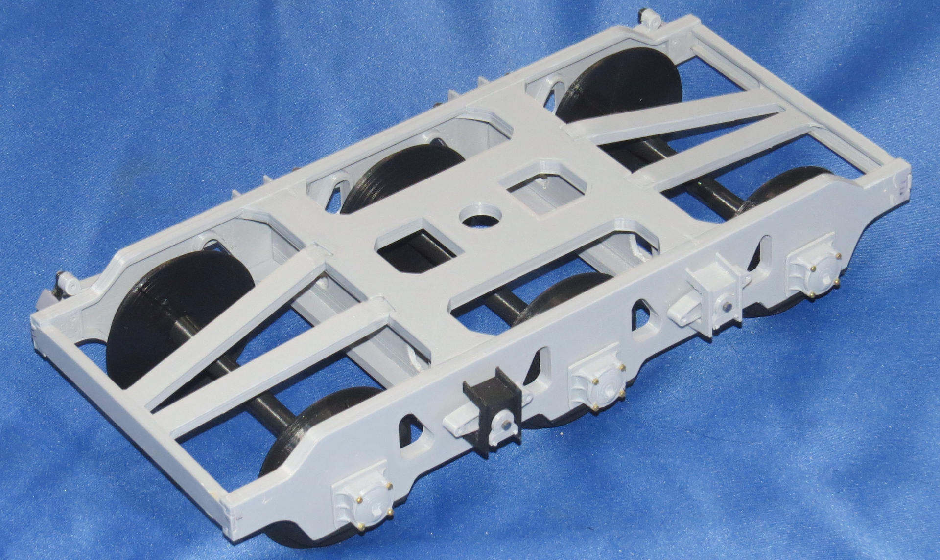
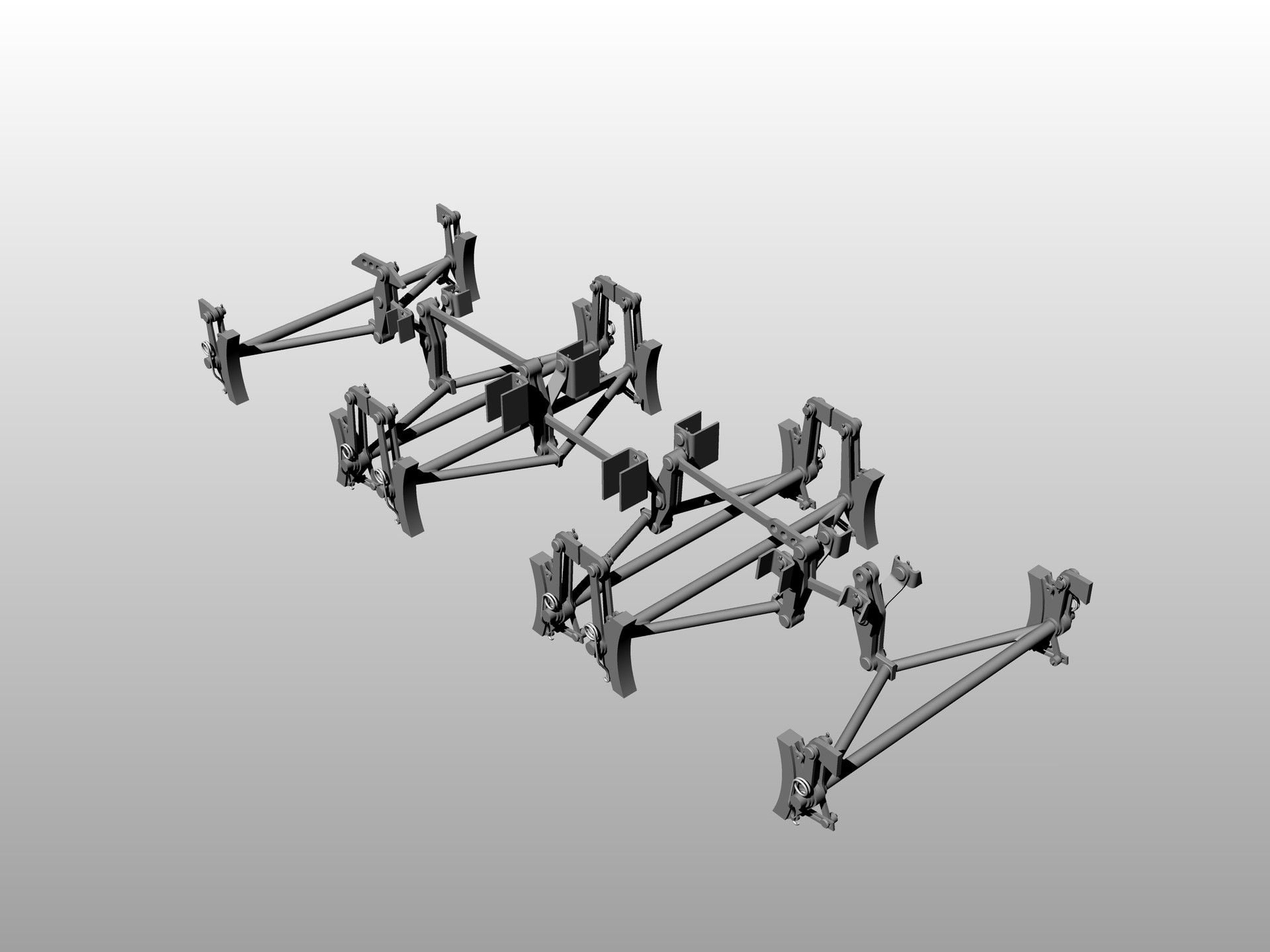
Next up was to tackle the bogies, there are many parts to the bogies due to the suspension components.
I actually assembled one of the bogies a while ago, not with details just the main framework axle boxes wheels and axles.
It was necessary to verify the design would work, since this was the first thing I had totally designed from scratch and had changed somewhat since I decided to do the suspension components and replace the straight axles with the tapered units.
The bogies went together as expected everything was bonded together, luckily my interlocking design is somewhat self-aligning so everything is pretty much already square. I used rubber bands and inexpensive clamps to make sure everything was tight before applying glue.
I then installed the wheels, axles and inner axle box assemblies and the lower plates that hold them in place, the redesigned axles have a big advantage over the straight axles I printed previously, the wheels are already perpendicular to the axle since they rest up against the shoulder I created on the axle.
On the straight axles the wheels would slide up and down the axles, it was necessary to create a jig to get them squared to the axles and to be the correct spread between the wheels to fit the 1/16th scaled track I had created.
The disadvantage is I will have to print different axles to fit the �G� scale track in Danville as that track width is quite different.

I started attaching the suspension components on this one.
Onto the suspension detail, I originally decided to use Hex head bolts to join the suspension components together for disassembly purposes, but as it turns out I only had enough for one side, so I decided to go with Button Head screws in black instead.
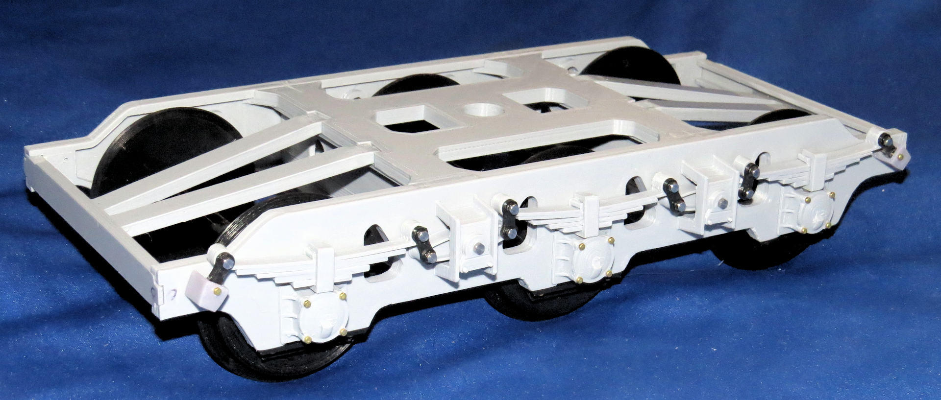
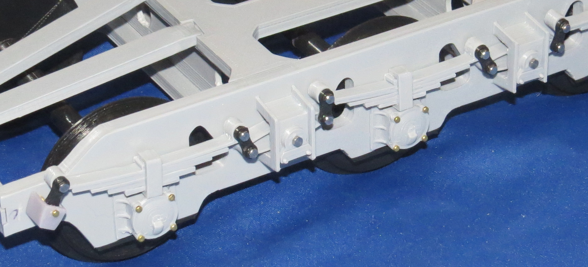
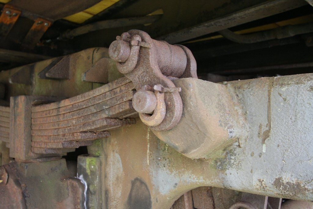
On the second set of bogies I may just use pins glued in place to hold everything together, that is how the real suspension was held in place with pins and very large horseshoe clips.
Most of the detail is just for show, although it is designed to be functional with plastic leaf springs it cannot support the weight of the rail car and the 13 lb. tank on top.
You may have noticed that only the outside links are in place on the suspension components the inside links not being necessary since it is just for show anyway I left them off, once painted flat black and buried under the bed it will be mostly unseen.
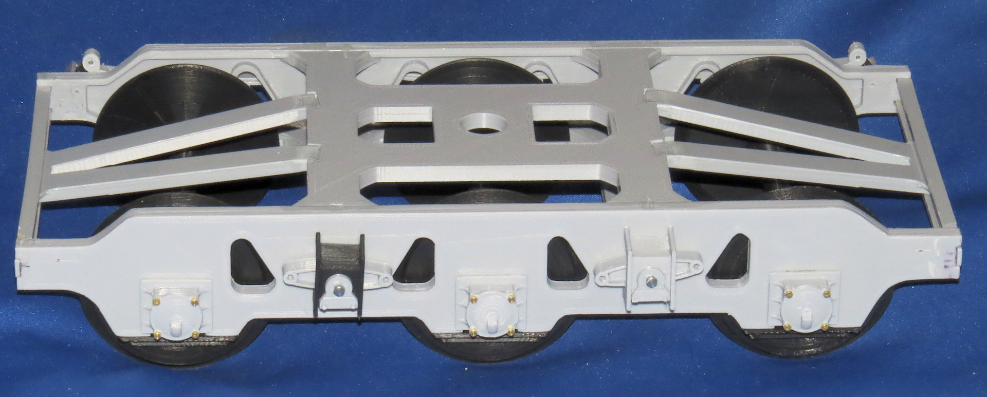
Also yet to be added is the alignment pins in the bottom of the leaf spring set that keeps them lined up with the axle boxes below.
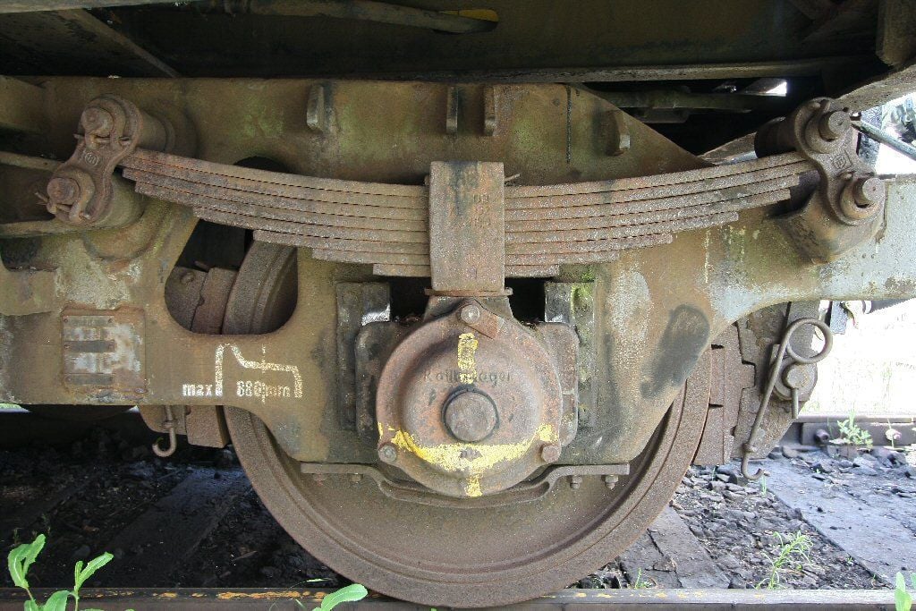
One major detail I omitted on the bogies is the braking system, it was fairly complex and looked to be a very large PITA and a lot of work designing and printing it. Theoretically it could be added later on, since I made it so the axles can be easily removed, however one would have to make the system somewhat functional so as to allow the brakes to swing out of the way when reinstalling the wheels and axles.
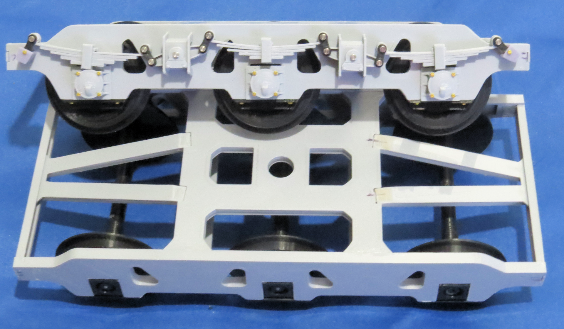
This is actually from a four axle rail car but they are similar. When I designed the suspension parts I knew they would not support the weight of an RC Tank so I limited the travel of the suspension to about 75% of the actual movement it was capable of. So it will look like it is correctly loaded but not bottoming out, which it actually will be.
While I had printed enough parts for the two bogies I ended up printing some additional parts in resin and some in PLA as I went along and made adjustments. I have still yet to print most of the detail parts for the second set of Bogies.
I am definitely a trial and error kind of guy, so it does not benefit me printing all the parts ahead of time, as there are almost always changes to be made or that I will make as I improve things.
It is better printing some parts as I go along and just print the key components that I will not change and that other parts will be adjusted to fit those components.
Many times I will create and print an alternate version of a part to see if the different version works better or worse than the original design. It wastes a little time but saves in the long run.
Common sense tells me it is better to print 12 parts that work well than print 12 that need adjustment or redesign and then print 12 more of the corrected part or rework the incorrect parts with files or whatever.
Sometimes I make more work for myself by adding details or functionality which by way of the ripple effect requires changes to other components.
The coupling hook and mechanism is an example, I did originally design it to look prototypical of the real type used on the real rail car, however, I decided a little late that I would make it swivel like the original unit as well.
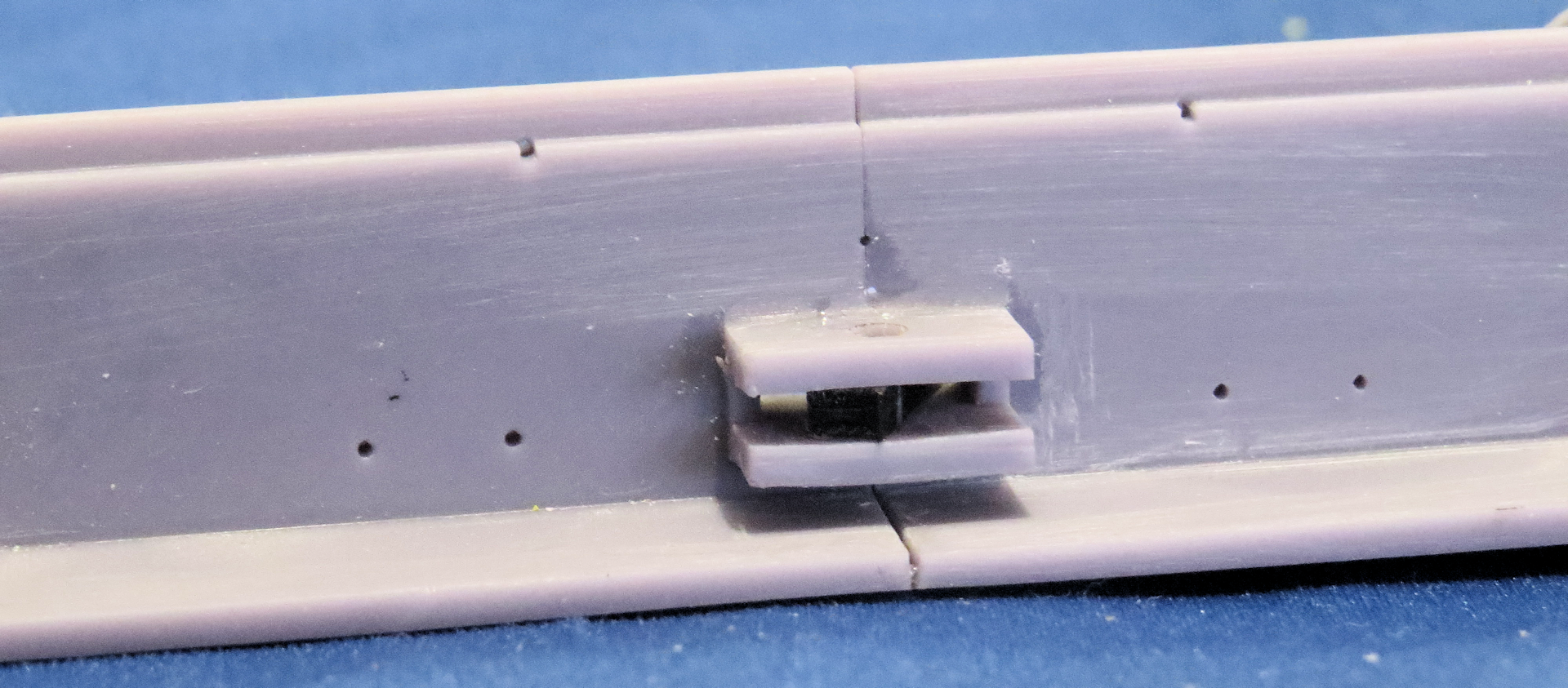
This required some changes to the hook as well as adding the support structure for that to happen, which meant changing the bed end plate sub plate, which I had already bonded to the sides of the bed.
This my friends is what the Dremel tool was invented for, I enlarged the hole in the sub plate to allow for the newly created mounting mechanism for the swiveling coupler hook, it ain�t pretty but the alternative would be much worse.
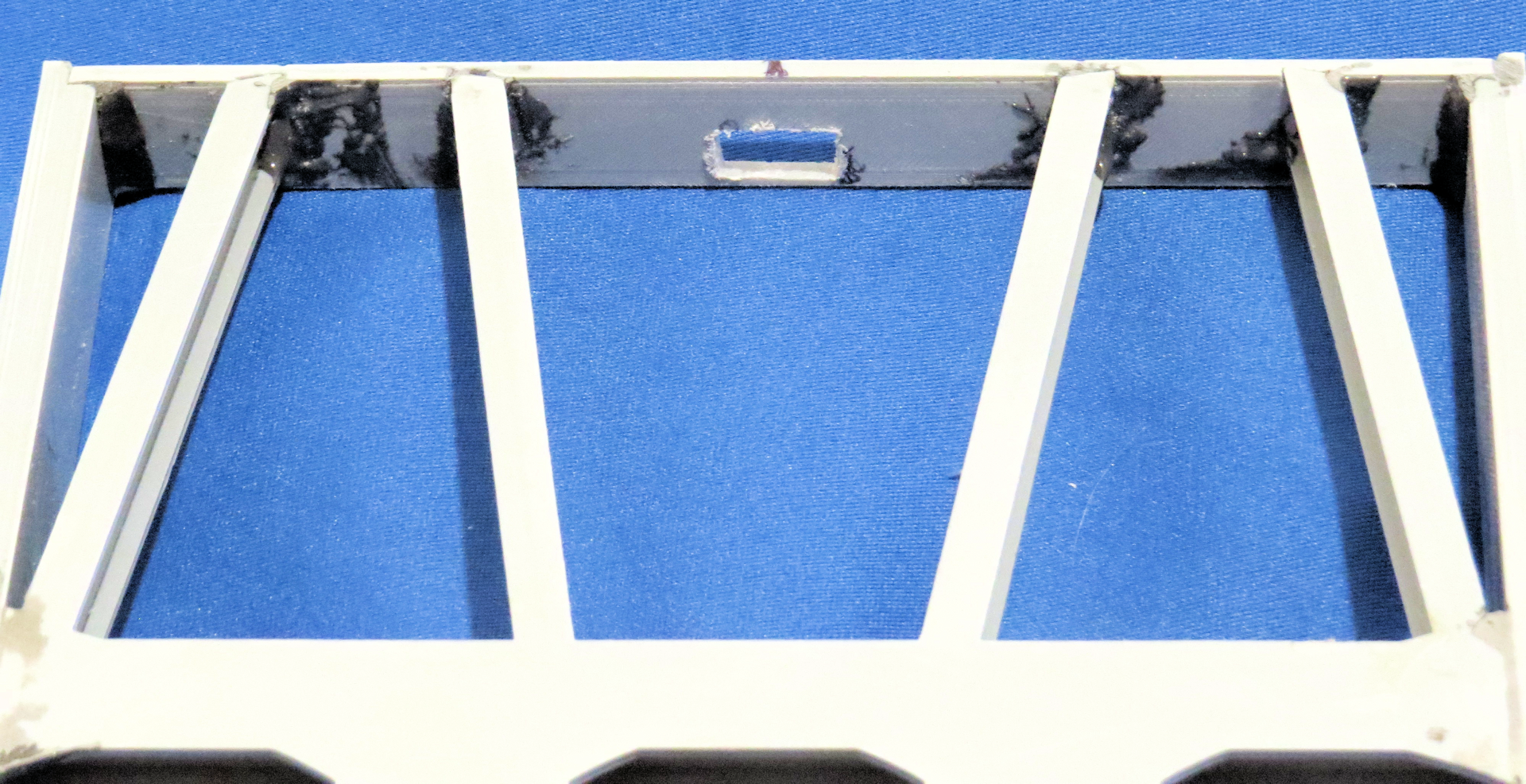
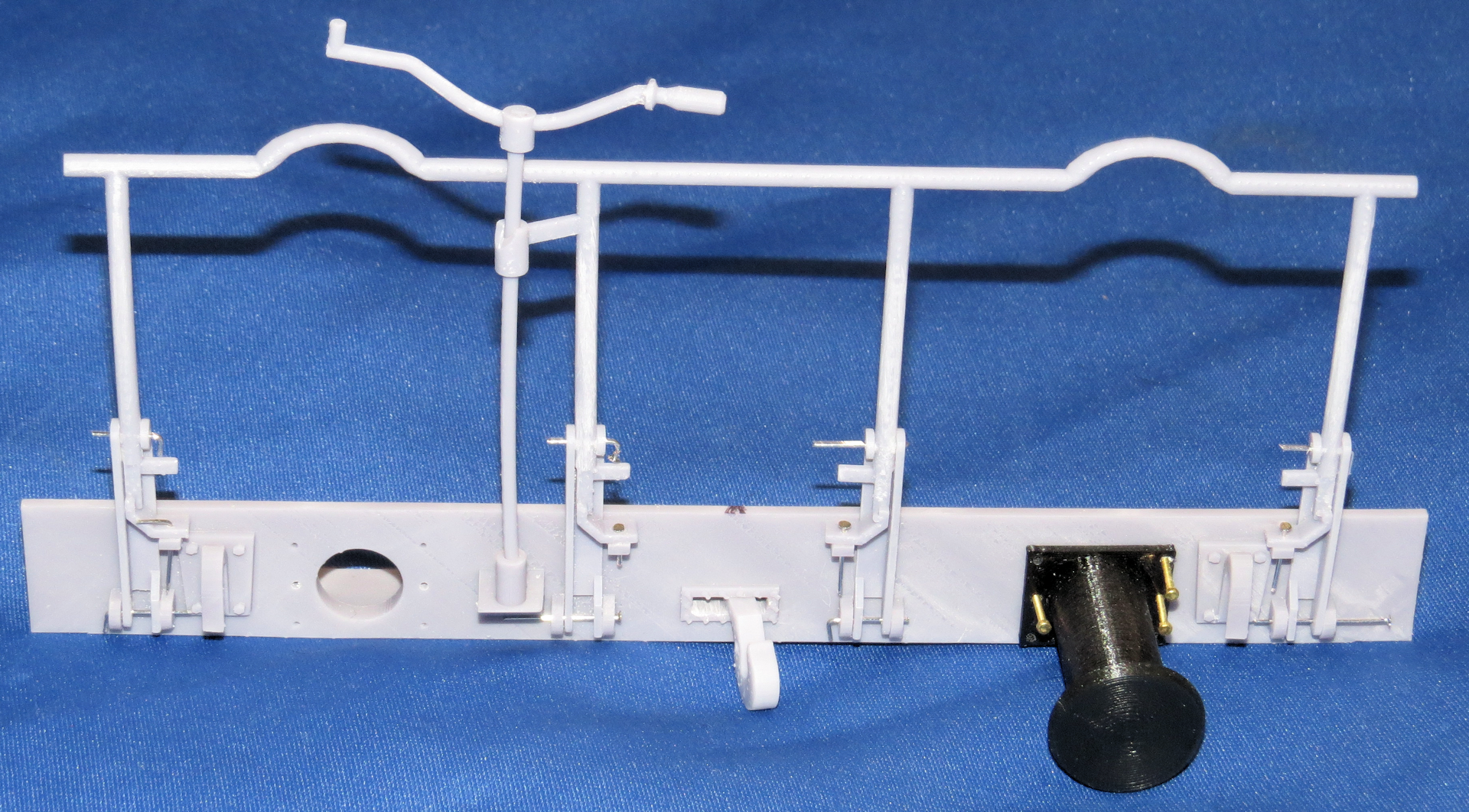
While I was at it I decided to try to resin print the end plate that the hook passes through, with all the additional parts as a complete unit. As you can see there are many parts attached to the end plate especially the endplate that has the folding handrail.
You may have noticed one of the endplate was two pieces joined together, I was unsure at the time that I could print the entire endplate as one piece as it is longer than the build plate on my resin printer.
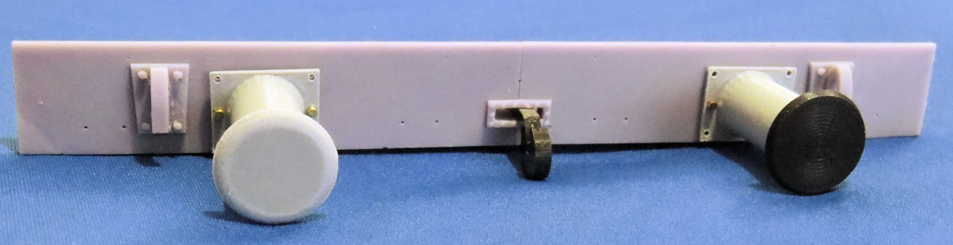
Handrail erect, pins holding everything in place temporarily This is a resin print of the handrail assembly, the handrail mounts and all of the detail was printed as one part only the handrail movable parts and buffers are added.

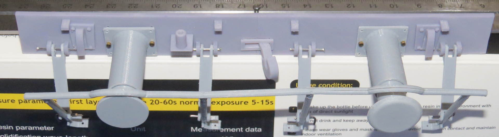
Handrail folded, Buffers are uneven as the springs are yet to be installed
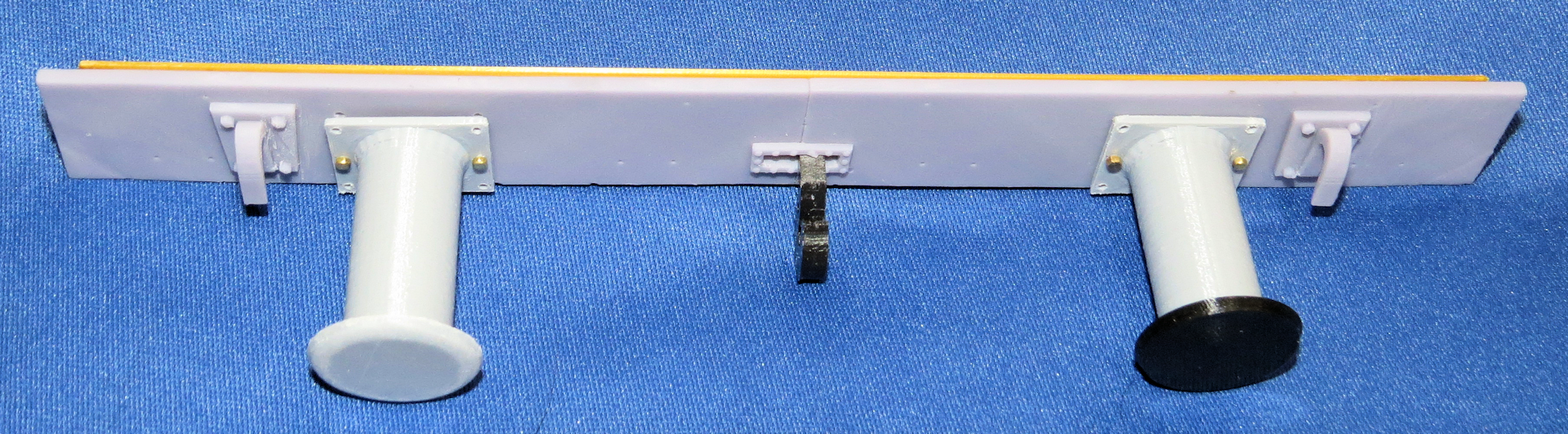
This is the non-handrail endplate there was only one handrail on the rail car
 From the Sabre manual showing the handrail folded.
I opted not to print the buffers as part of the endplate the buffers are printed in PLA for now I may reprint them in ABS or ASA later on depending on how well the PLA holds up, I knew they may get damaged during use, so I made these easily replaceable as is the entire endplate, since it is held in place by the bolts holding the buffers in position.
So all the component parts included as part of the resin endplate are the eight mounts for the folding handrail upright stanchions and locking tabs as well as the inverted hooks for the tow cables and the base for the braking handle in addition to the new coupler mount.
The original bed that I designed and printed has no accommodation for the swiveling coupler mount so I will rework the ends to accommodate the endplates with the coupler mounts.
In case anyone was curious as to why so long between posts, I have been working on several other project while doing this one, here are pics of some of my other projects.
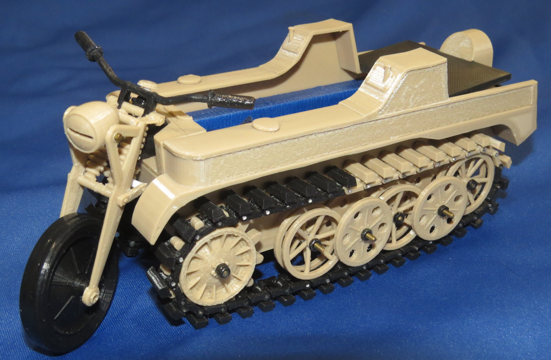
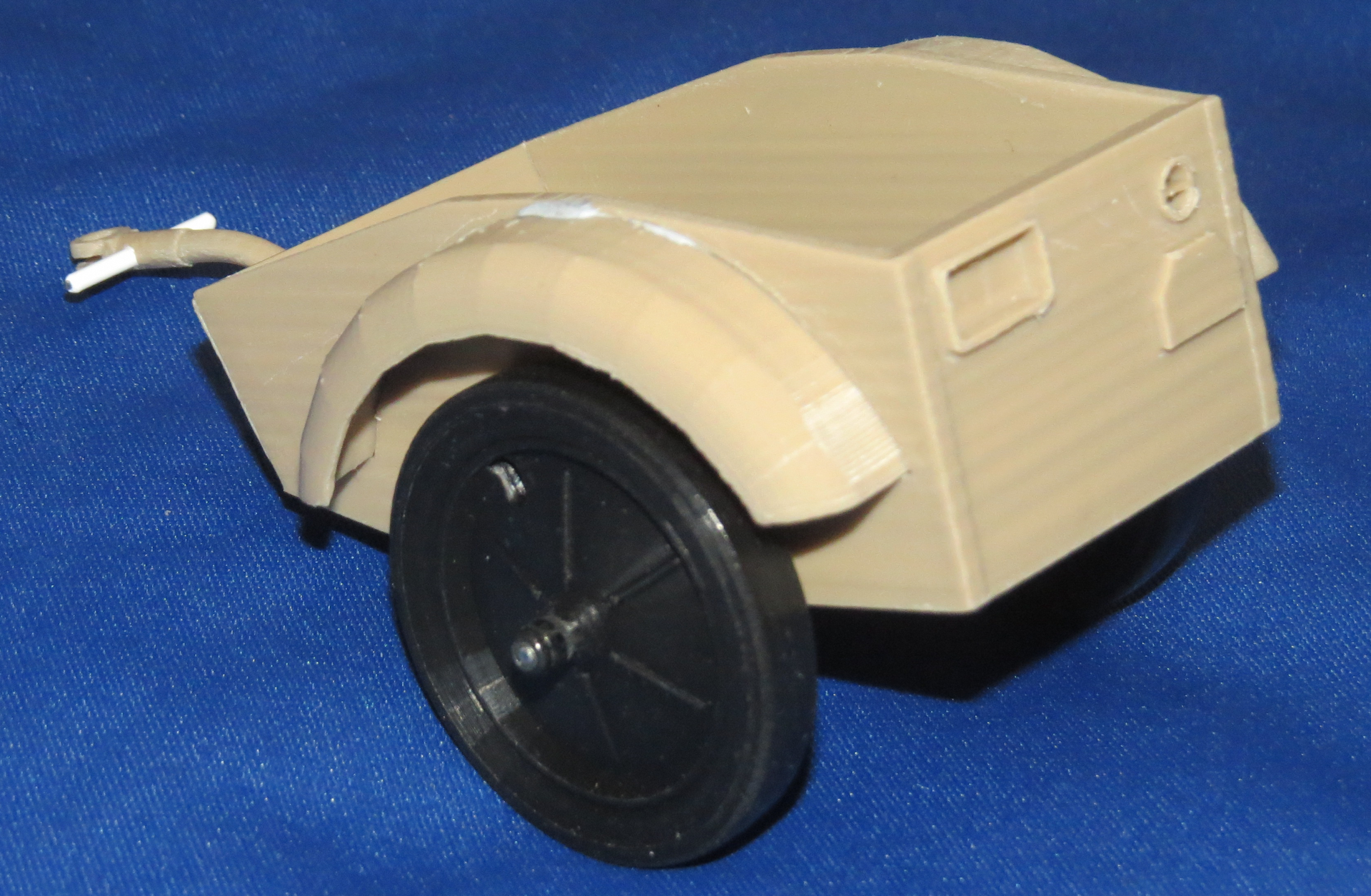

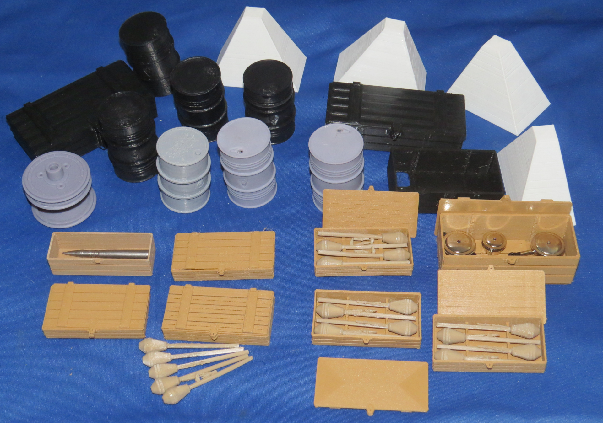

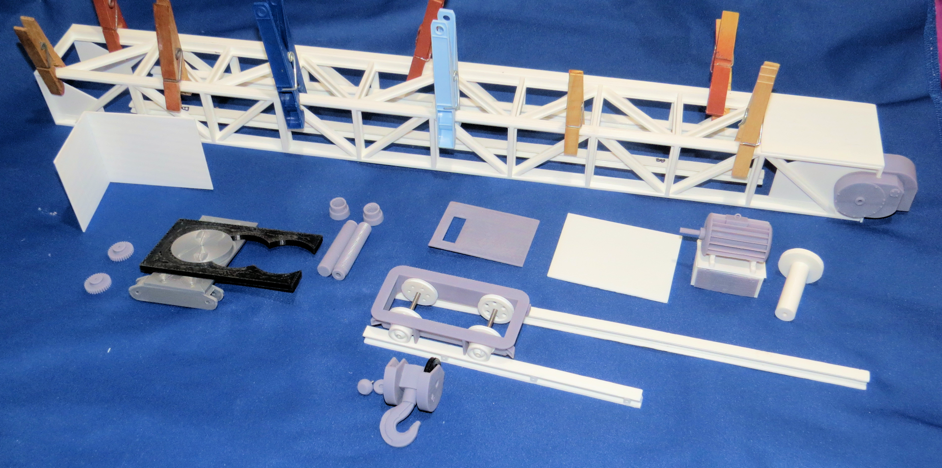
Some of these are nearing completion.
All for now