


CG - What am I Doing Wrong?
 07-17-2022, 06:16 AM
#1

Thread Starter
Thanks in advance to any advice.
I recently acquired a 1/4 scale Yak 54 ARF that someone had begun, but never finished. It came w/o any instructions, so I had no clue where the CG should be.
I used a couple of the online CG calculators plus I did the calculations manually, finding for the MAC and going with 25% of MAC as my CG point. All the calculations were within a few hundredths of an inch the same.
So I ended up adding about 3# of lead to the nose plus extending the engine mounts 1/2" to try and get it to balance. It came out slightly nose heavy which is just what I wanted for the maiden flight.
Well, you can guess what happened...it was sooo nose heavy that I could barely control it, and when I slowed to land it plummeted straight into the ground on final! Luckily, only the firewall engine box and cowl were destroyed, so I'll rebuild it next winter.
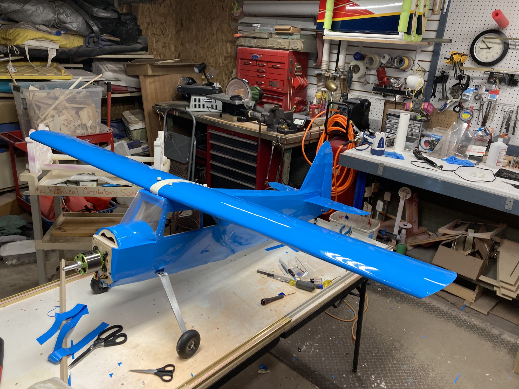
Now it's on to a scratch-built 1/5th scale Rearwin Speedster I've been making using an old NexStar wing I had in the shop. After getting it finished, I did the same CG calculators, and it shows a CG point of 2.35" from the leading edge @ 25% MAC. The wing has a 10.5" chord with no sweep and a half span of 34.75".
So, I check the balance at this CG and it is so tail heavy it's ridiculous. I moved the batteries as far forward as possible and it still won't balance! I'd have to add a bunch of lead to the nose again on this plane. I realize the Rearwin diesign has a long tail moment to counterbalance the very heavy engine they put into it.
Is there something I'm missing here? something I don't understand about MAC and CG?
Is
I recently acquired a 1/4 scale Yak 54 ARF that someone had begun, but never finished. It came w/o any instructions, so I had no clue where the CG should be.
I used a couple of the online CG calculators plus I did the calculations manually, finding for the MAC and going with 25% of MAC as my CG point. All the calculations were within a few hundredths of an inch the same.
So I ended up adding about 3# of lead to the nose plus extending the engine mounts 1/2" to try and get it to balance. It came out slightly nose heavy which is just what I wanted for the maiden flight.
Well, you can guess what happened...it was sooo nose heavy that I could barely control it, and when I slowed to land it plummeted straight into the ground on final! Luckily, only the firewall engine box and cowl were destroyed, so I'll rebuild it next winter.
Now it's on to a scratch-built 1/5th scale Rearwin Speedster I've been making using an old NexStar wing I had in the shop. After getting it finished, I did the same CG calculators, and it shows a CG point of 2.35" from the leading edge @ 25% MAC. The wing has a 10.5" chord with no sweep and a half span of 34.75".
So, I check the balance at this CG and it is so tail heavy it's ridiculous. I moved the batteries as far forward as possible and it still won't balance! I'd have to add a bunch of lead to the nose again on this plane. I realize the Rearwin diesign has a long tail moment to counterbalance the very heavy engine they put into it.
Is there something I'm missing here? something I don't understand about MAC and CG?
Is


 07-17-2022, 08:22 AM
#3
Meseems you're fixated on having the C/G at 25% MAC. Actually, the location of the C/G is heavily dependent on the airplane's configuration and even the wing's airfoil.
The C/G calculators usually calculate the location of the Neutral Point (NP, in % of MAC) and then you choose a C/G location ahead of the NP. The difference (also measured in % of MAC) is also called the static stability margin. The calculator may even let you choose a stability margin and then calculate the C/G location.
For the Yak I'd assume only 2% to 5% MAC but for your blue bird even 5% to 15% as you see fit, that is depending how much decalage there is and how much stability you like.
Probably you'll come up with about 30% MAC for the Yak and 40% for the blue bird.
FWIW.
 07-17-2022, 09:57 AM
#4
Thread Starter
I think maybe I need to move the motor out at least an inch to get in the ballpark. It'll look more scale that way, too.
 07-17-2022, 10:00 AM
#5
Thread Starter
Meseems you're fixated on having the C/G at 25% MAC. Actually, the location of the C/G is heavily dependent on the airplane's configuration and even the wing's airfoil.
The C/G calculators usually calculate the location of the Neutral Point (NP, in % of MAC) and then you choose a C/G location ahead of the NP. The difference (also measured in % of MAC) is also called the static stability margin. The calculator may even let you choose a stability margin and then calculate the C/G location.
For the Yak I'd assume only 2% to 5% MAC but for your blue bird even 5% to 15% as you see fit, that is depending how much decalage there is and how much stability you like.
Probably you'll come up with about 30% MAC for the Yak and 40% for the blue bird.
FWIW.
The C/G calculators usually calculate the location of the Neutral Point (NP, in % of MAC) and then you choose a C/G location ahead of the NP. The difference (also measured in % of MAC) is also called the static stability margin. The calculator may even let you choose a stability margin and then calculate the C/G location.
For the Yak I'd assume only 2% to 5% MAC but for your blue bird even 5% to 15% as you see fit, that is depending how much decalage there is and how much stability you like.
Probably you'll come up with about 30% MAC for the Yak and 40% for the blue bird.
FWIW.
07-17-2022, 03:48 PM
#6
Join Date: Nov 2010
Location: Coffs Harbour NSW, AUSTRALIA
Posts: 1,563
Likes: 0
Received 71 Likes
on
67 Posts
Mate, these type of models are so CG forgiving if you set it at some 1/3 of the wing cord I can't understand it became uncontrolable. Thrust of the motor plays also a part, and hope you had enough travel adjustments on control tabs!
07-17-2022, 04:00 PM
#7
Thread Starter
Ok, I did the calculations and I don't like what I found. I used standoffs to move the motor 1" forward
First of all, the airplane weighs 11# with 2# of 8s batteries.
Wing Area = 730 sq in
Wing Loading = 34.72oz/sq ft, or 15.42 oz/cu ft (which is unacceptable for a high wing scale sport plane)
With Static Margin set to 15%, 10%:
From Wing Root LE to AC = 2.63, 2.63
From WRLE to NP = 5.14, 5.14
From WRLE to CG = 3.56, 4.09
I can achieve balance with batteries forward and 2oz of lead for the 15% SM, probably wouldn't need the lead @ 10%.
My concern tho, is the wing loading. to get this pig to fly right, I'll likely have to build the larger Rearwin wing.
Any thoughts?
07-17-2022, 04:01 PM
#8
Thread Starter
Which airplane are you talking about? The Yak or the blue high wing?
07-17-2022, 04:37 PM
#9
Join Date: Nov 2010
Location: Coffs Harbour NSW, AUSTRALIA
Posts: 1,563
Likes: 0
Received 71 Likes
on
67 Posts
I work more logical metrics, 105g/dm2 sound pretty high wing load for any above, the "Yak" or the Blue high wing one! Should't be more than about 80g/dm. Enlarging your flying surfaces will help reduce your high wing load.
I have recently converted one of my large turbine powered foamy to EDF, unfortunately adding 2 kilos of extra weight!, especialy while landing! Ease fix, I have added canards and winglets to reduce the w/load, it works great.
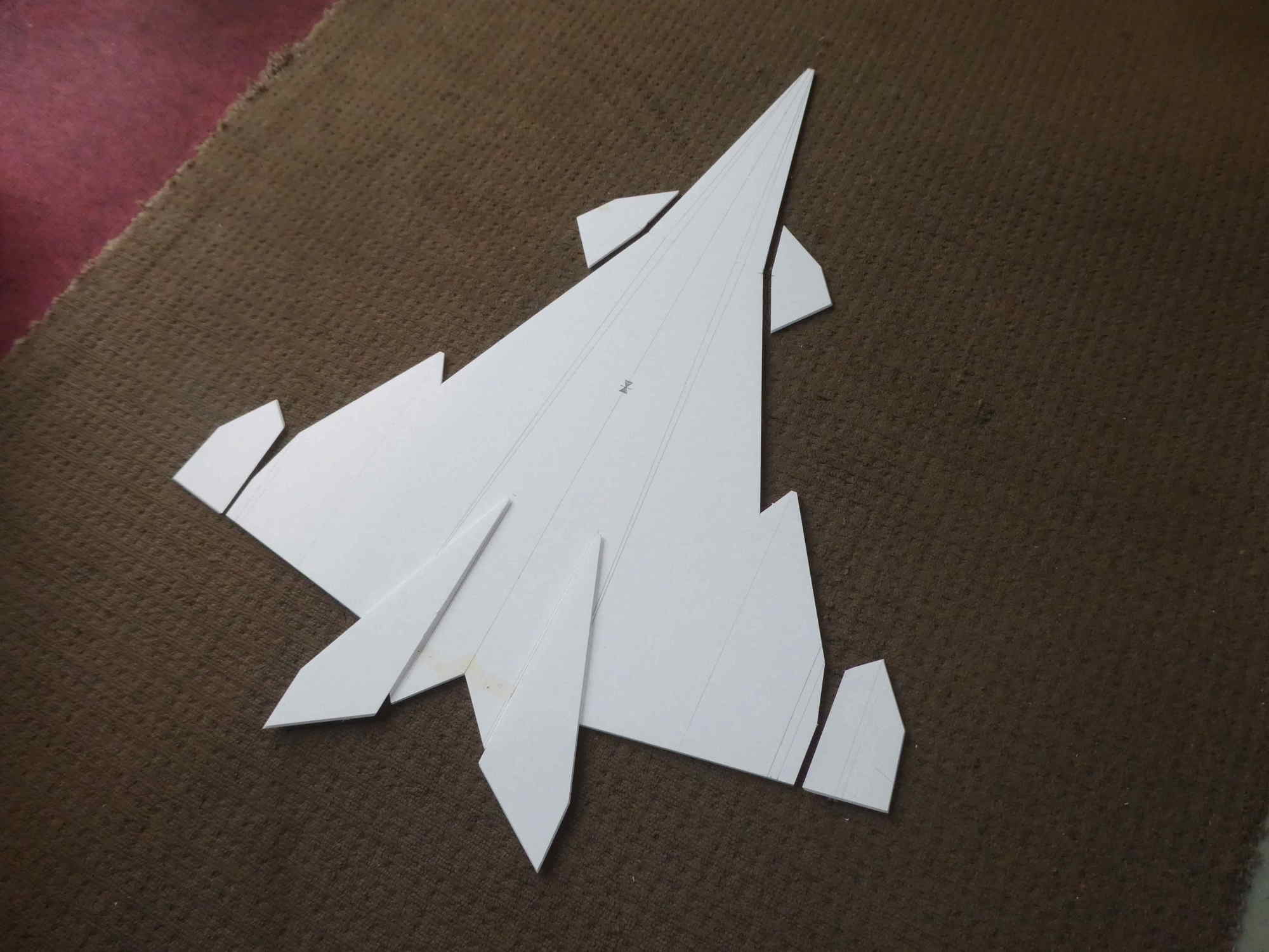
Enlarged flying area.
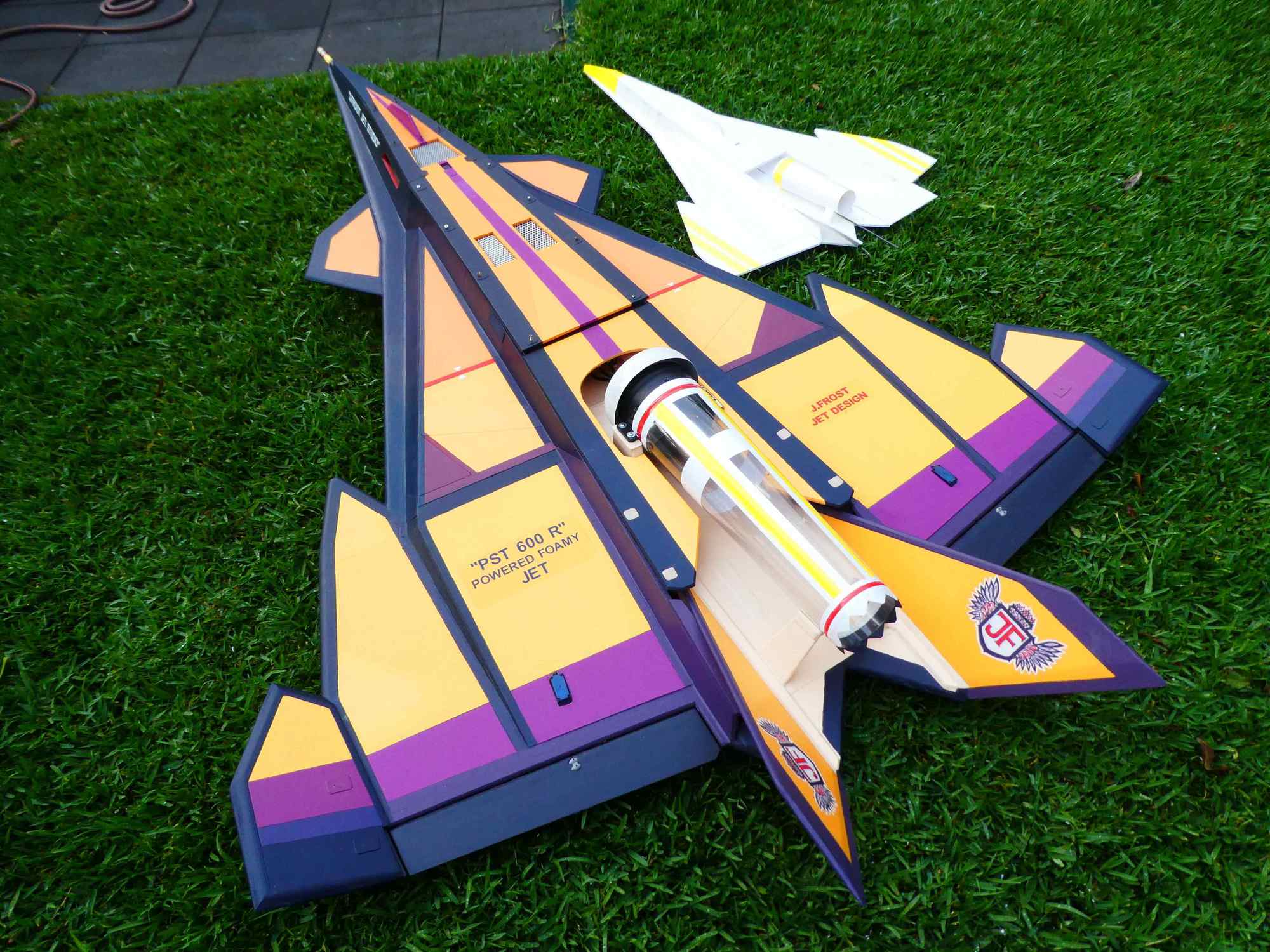
Easy fix making it look even more impressive.
I have recently converted one of my large turbine powered foamy to EDF, unfortunately adding 2 kilos of extra weight!, especialy while landing! Ease fix, I have added canards and winglets to reduce the w/load, it works great.
Enlarged flying area.
Easy fix making it look even more impressive.
07-20-2022, 12:08 PM
#10


Join Date: Oct 2002
Location: Chilliwack, BC, CANADA
Posts: 12,425
Likes: 0
Received 22 Likes
on
19 Posts
Ok, I did the calculations and I don't like what I found. I used standoffs to move the motor 1" forward
First of all, the airplane weighs 11# with 2# of 8s batteries.
Wing Area = 730 sq in
Wing Loading = 34.72oz/sq ft, or 15.42 oz/cu ft (which is unacceptable for a high wing scale sport plane)
With Static Margin set to 15%, 10%:
From Wing Root LE to AC = 2.63, 2.63
From WRLE to NP = 5.14, 5.14
From WRLE to CG = 3.56, 4.09
I can achieve balance with batteries forward and 2oz of lead for the 15% SM, probably wouldn't need the lead @ 10%.
My concern tho, is the wing loading. to get this pig to fly right, I'll likely have to build the larger Rearwin wing.
Any thoughts?
First of all, the airplane weighs 11# with 2# of 8s batteries.
Wing Area = 730 sq in
Wing Loading = 34.72oz/sq ft, or 15.42 oz/cu ft (which is unacceptable for a high wing scale sport plane)
With Static Margin set to 15%, 10%:
From Wing Root LE to AC = 2.63, 2.63
From WRLE to NP = 5.14, 5.14
From WRLE to CG = 3.56, 4.09
I can achieve balance with batteries forward and 2oz of lead for the 15% SM, probably wouldn't need the lead @ 10%.
My concern tho, is the wing loading. to get this pig to fly right, I'll likely have to build the larger Rearwin wing.
Any thoughts?
Typically models in this size range are more like 6 to 6.5 lbs. And at that weight it would likely balance well and fly in a manner like the Nexstar that the wing came from.
I'd start by weighing the empty model. I'm thinking that you are making the wing loading higher by your use of two 8S pack in parallel to power what I suspect is an overly strong motor for the size of the model. If the empty airframe with servos only and no packs or motor is down around 4 to 5 lbs then I'd start from there with a more suitable and lighter motor and battery setup. Find a set that works out to more like 6 to 6.5lbs flying weight. For sport flying a model of that size and weight would do fine with around 100 watts/lb of weight. So 600 to 650 watts. And that sort of power is easily had with 4S or 5S packs powering motors that are around 6 to 8 oz in weight. For example an EFlite Power 32 is good for up to 700 watts and weighs 7 oz.
If the empty airframe other than servos is in fact up around 6 to 7 lbs already and the motor and packs is raising it to 11lbs then I don't see any saving it other than starting over with a keener eye to keeping the fuselage and tail surfaces a lot lighter. Yes, it'll fly. But the point of flying our models is that they should be fun to fly. And 11lbs on a 730 square inch Nexstar wing would not be my idea of fun by a long stretch.
The good news is that you seem to have your misunderstandings about the relationship of neutral points and 25% Aerodynamic Centers cleared up. The results in the quote above for distances on the 10" wing chord for the NP and CG locations for the SM values looks dandy.
07-30-2022, 01:00 PM
#11
Thread Starter
Ok, so I've decided to build a new wing for the Rearwin Speedster that is scaled down from the 1/4 scale Reawin I had before. Now onto the Yak.
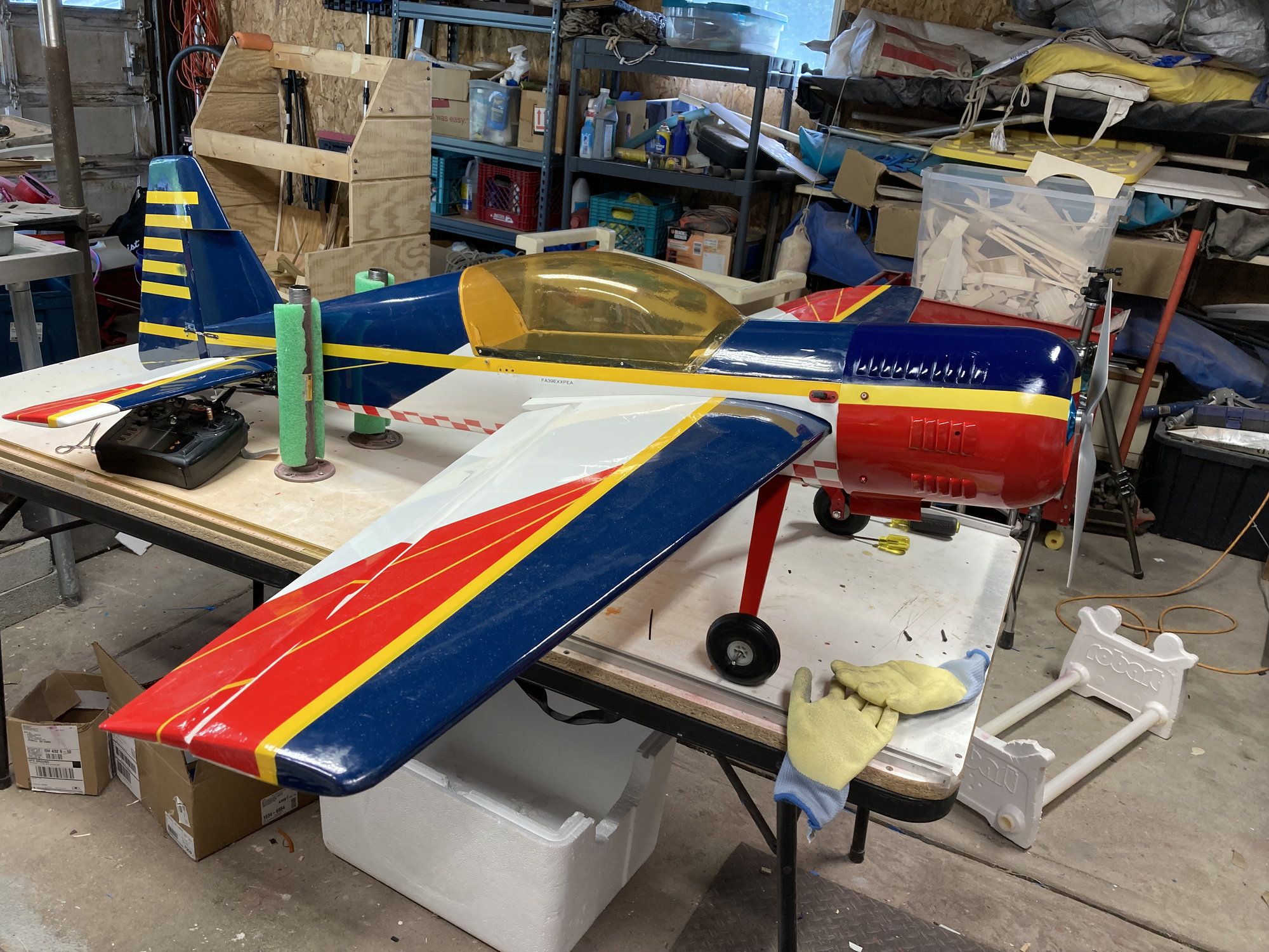
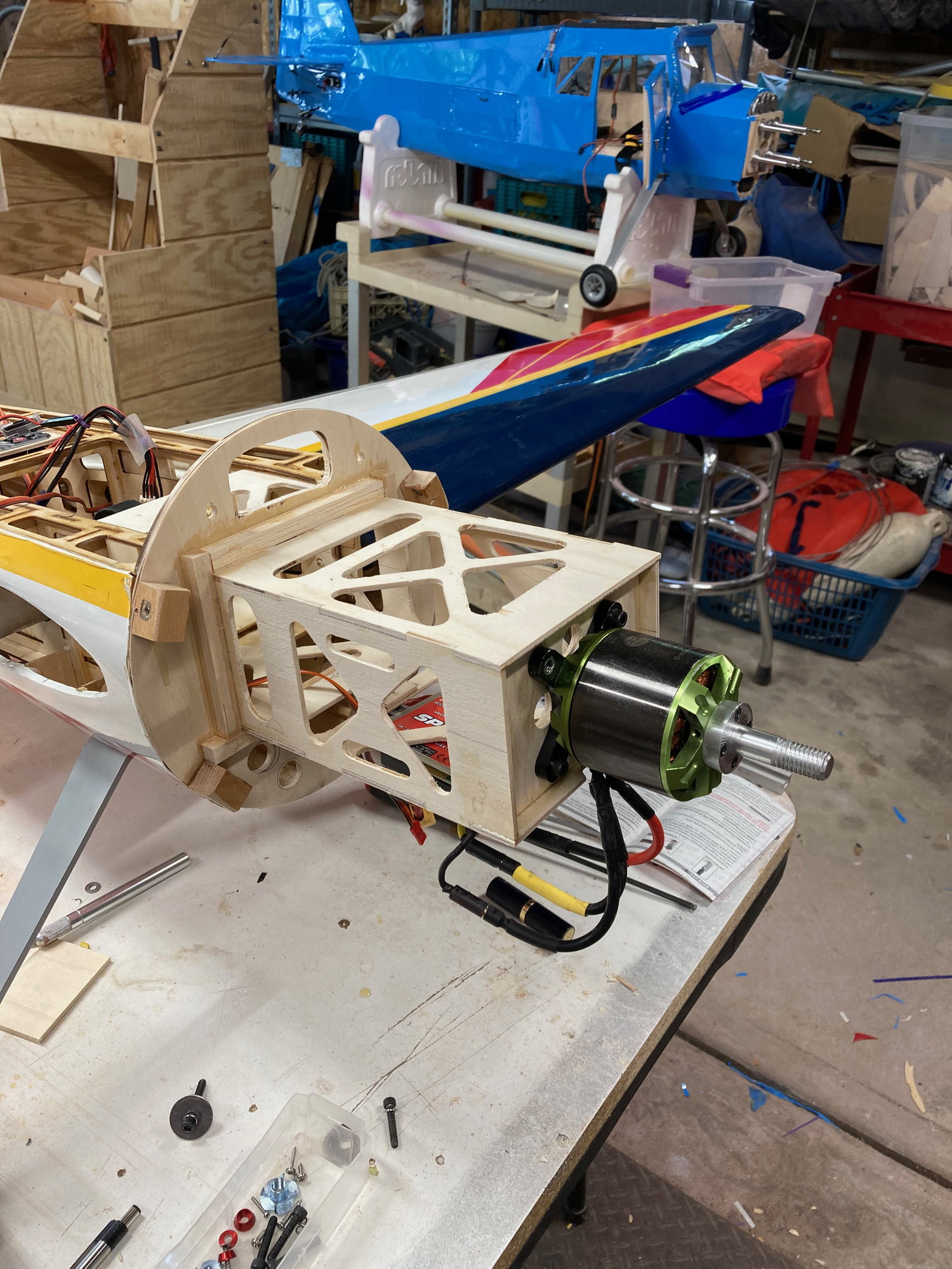
I've rebuilt the nose of the Yak 54 with a new motor box and decided to go electric. I repaired any other slight damage there was to the fuselage, reglassed and painted the broken cowl, and added a battery tray & 2 2s receiver batteries.
Now back to the question of CG.
I was able to find an old build thread on RCU that showed me that the plane i have is a Hyperion Yak 54 120e. The builder states that the manual says the CG is located at the back edge of the yellow stripe on the wing, 6 3/8" from the LE at the root. He has successfully flown the plane with that as a starting CG.
Using an online CG calculator, I come up with (using these numbers)
Root Chord = 17.75"
Tip Chord = 9.00"
Sweep = 1.75"
1/2 Span = 32.5"
Using 30% MAC, I come up with a CG of 4.97"
Quite a difference from 6 3/8"! So, what number do I trust?
07-30-2022, 04:12 PM
#12
Join Date: Nov 2010
Location: Coffs Harbour NSW, AUSTRALIA
Posts: 1,563
Likes: 0
Received 71 Likes
on
67 Posts
You are worrying too much! These type of model are so forgiving CG-wise it wouldn't make much difference if you move it inch fore or back. To start with set it at the spar position!
Thrust of the motor plays another part, how did you set that?
The best thing you can do, get someone with an experience flying these type of models at your flying field to help you to set it up and test fly it for you if you don't trust yourself. (That's what the Clubs and memberships are for)
Thrust of the motor plays another part, how did you set that?
The best thing you can do, get someone with an experience flying these type of models at your flying field to help you to set it up and test fly it for you if you don't trust yourself. (That's what the Clubs and memberships are for)
Last edited by Joseph Frost; 07-30-2022 at 04:21 PM.
07-30-2022, 05:08 PM
#13
Thread Starter
You are worrying too much! These type of model are so forgiving CG-wise it wouldn't make much difference if you move it inch fore or back. To start with set it at the spar position!
Thrust of the motor plays another part, how did you set that?
The best thing you can do, get someone with an experience flying these type of models at your flying field to help you to set it up and test fly it for you if you don't trust yourself. (That's what the Clubs and memberships are for)
Thrust of the motor plays another part, how did you set that?
The best thing you can do, get someone with an experience flying these type of models at your flying field to help you to set it up and test fly it for you if you don't trust yourself. (That's what the Clubs and memberships are for)
Ive been down that path before re: having a more experienced pilot maiden a plane. Only found one guy in my club that will do that and he�s mostly on the road doing national stuff for the NASA.
07-31-2022, 05:30 AM
#15

Interesting, why down thrust on an aerobatic airplane and not side thrust?
That said, Joseph is correct about the CG being rather forgiving on that model. I would put it at 5.5� from the leading edge at the root. Run rather conservative throws for the first few flights. Without any right thrust it will want to veer left on take off and vertical lines.
That said, Joseph is correct about the CG being rather forgiving on that model. I would put it at 5.5� from the leading edge at the root. Run rather conservative throws for the first few flights. Without any right thrust it will want to veer left on take off and vertical lines.
07-31-2022, 06:11 AM
#16
Thread Starter
I agree with speedracerntrixie about the down thrust. I just added 1 degree of right thrust.
I'll give the 5.5" CG a go as a start. Hopefully my props will arrive as scheduled today so I can try it tomorrow.
Thanks guys.
I'll give the 5.5" CG a go as a start. Hopefully my props will arrive as scheduled today so I can try it tomorrow.
Thanks guys.
07-31-2022, 03:32 PM
#17

I'm wondering how new you are to designing your own airframe/kit bashing using other parts. This is not a criticism it's just building things with the proper relationships that insure a controllable airframe is an acquired skill. For instance balancing an airframe will not make it a good flyer if by adding weight you increase the wing loading to the point the model wants to stall/snap when ever you slow it down for a landing. There is a very good book for anyone who is considering branching out on their own to build an idea they have decided would make an appealing model.
This book is a wealth of good information for anyone with a desire to turn their ideas into actual flying models.
This book is a wealth of good information for anyone with a desire to turn their ideas into actual flying models.
07-31-2022, 04:09 PM
#18
Thread Starter
Yes, it is an acquired skill - acquired by building/kit bashing, whatever you wish to call it, and crashing then learning from your mistakes.
That is the advice I was given by one of the best scale builders in the world. I�m not wealthy enough to have a hanger full of foamies and arfs to always have something at the ready to fly, so I build what I can with what I have on hand, buying wood and parts as I go. But sometimes I�m so anxious to get out to the field and fly I make errors in judgement. Lesson learned. That�s why this time around I�ve restored the Yak to the electric powered plane it was designed as, relentlessly searched to find the maker and some instruction on weight, cg, recommended throws, prop size, etc., gone over everything 3x, asked for advice on RCU, and made myself a thorough typewritten pre-flight checklist. Tomorrow, when my props arrive, I will balance them then ground test the power plant with different props to see which size/pitch gives me the best performance as measured by my wattmeter.
Regarding the Rearwin Speedster (blue one), that one will sit on the bench until I build the correct wing for it - a scale Rearwin Speedster wing based on the Bridi 1/4 scale design (scaled down to 1/5). The wing I originally had planned to use was an old Nexstar wing that was given to me. After doing the calculations, I realized the wing loading would be much too high, so I scrapped that idea.
07-31-2022, 05:07 PM
#19
Join Date: Nov 2010
Location: Coffs Harbour NSW, AUSTRALIA
Posts: 1,563
Likes: 0
Received 71 Likes
on
67 Posts
Interesting, why down thrust on an aerobatic airplane and not side thrust?
That said, Joseph is correct about the CG being rather forgiving on that model. I would put it at 5.5� from the leading edge at the root. Run rather conservative throws for the first few flights. Without any right thrust it will want to veer left on take off and vertical lines.
That said, Joseph is correct about the CG being rather forgiving on that model. I would put it at 5.5� from the leading edge at the root. Run rather conservative throws for the first few flights. Without any right thrust it will want to veer left on take off and vertical lines.
 08-02-2022, 09:17 PM
#22
Join Date: Oct 2002
Location: Chilliwack, BC, CANADA
Posts: 12,425
Likes: 0
Received 22 Likes
on
19 Posts
.....Now back to the question of CG.
I was able to find an old build thread on RCU that showed me that the plane i have is a Hyperion Yak 54 120e. The builder states that the manual says the CG is located at the back edge of the yellow stripe on the wing, 6 3/8" from the LE at the root. He has successfully flown the plane with that as a starting CG.
Using an online CG calculator, I come up with (using these numbers)
Root Chord = 17.75"
Tip Chord = 9.00"
Sweep = 1.75"
1/2 Span = 32.5"
Using 30% MAC, I come up with a CG of 4.97"
Quite a difference from 6 3/8"! So, what number do I trust?
I found a drawing for the Yak54 online and measured off the dimensions as needed for a full and proper CG calculation per the following online CG calculator.
Aircraft Center of Gravity Calculator (rcplanes.online)
I entered 4 (as in 4%) for the desired stability margin which for a model of this sort should be a reasonable starting point. The Neutral Point came out to be 40%. And the CG location for the 4% stability margin is 35%. Both with reference to the root chord leading edge. This point being the meeting point at the center line within the fuselage of the two angled leading edges. So some extension or compensation for this would be needed.
Using your 17.75" root chord 35% would put the balance point at 6.2 inches back from the leading edge at the root chord. That's extremely close to the stated 6.375" back.
The point at which the model would technically be neutral in pitch would be at the 40% point or 17.75 x 0.40 = 7.1 inches back. Neutral is neutral. Not unstable but not stable either. So either is still pretty safe.
Your stated 30% MAC ends up being 29.4% back from the root leading edge or 17.75 x 0.294 = 5.15" back from the root leading edge. That's pretty darn close to your 4.97. We can put that down to me working with a small scale drawing vs your actual model sizes.
But the point here is that just using 30% of the MAC in this case with the very big horizontal tail would result in being rather on the nose heavy side Even with the 4% stability margin it would be moderately self stable in pitch and pull itself out of a dive if left alone much like a typical sport model. That would be a nice setup for a first flight or two. But if you're a hardcore Yak style guy that spends close to half the flight upside down you'll likely want to bump the CG back in small steps to end up closer to the 40% neutral point so the model stays pointed where you leave it. Makes knife edge in particular somewhat more easy. And needs less forward pressure when inverted.
But check over your actual model and poke ALL the proper numbers into the boxes of that calculator. It'll be close but perhaps there will be some slight changes from what I saw using the small scale drawing.
08-03-2022, 03:20 AM
#23
Thread Starter
Thanks for the very in-depth explanation. I do understand the concepts of AC, NP, Stability Margin, and factoring tail area into cg calculations. For brevity’s sake I just chose to post the simplified version of the numbers I used to arrive at a cg location.
I’ve actually used the online calculator you linked to, asa well as a calculation method for full-scale aircraft, and came up with very similar numbers. I even ran the numbers manually. None of which were close to the cg position the one person I know of who actually flew this particular model used. That is why I was posing the question. Granted, he is a 3D flyer, and I’m not, so I suspect his stability margin was was not gonna be what I wanted at 15%. Plus, I suspect he just used the manual’s stated cg and let it go at that since there was no mention in his blog of him doing anything greatly technical in setting up his airplane.
Right now the Yak is balancing at the forward edge of the yellow stripe which equates to just a tad over 5” from the LE at the root. Trusting that those who have stated here that this aircraft has a very forgiving cg range, I will go with that to start.
Thank you.
08-03-2022, 05:49 AM
#24
Stick to that plan and you will be fine. 40% is way too far back. People put way too much thought into CG placement for this type of airplane. Reality is that it will have a range of about 2� where it will safely fly. Odds are that you will need to adjust anyways. Too many variables to nail it down without flying it and adjust based on flight characteristics. I�ve never used a CG calculator and have set up dozens of IMAC and Pattern models. To really get it fine tuned you also need to know where your wing and stab incidences are as they will influence CG position too.
08-03-2022, 06:26 AM
#25
Thread Starter
Thanks speedracerntrixie.
I do understand about the incidences affecting cg. My goal for now is to get it in the air, see how she flies and then start fine tuning the trimming. I just wanted to be sure I was close enough on the CG that I’m not fighting an overly tail heavy or nose heavy aircraft like I did with the ic engine in it
I do understand about the incidences affecting cg. My goal for now is to get it in the air, see how she flies and then start fine tuning the trimming. I just wanted to be sure I was close enough on the CG that I’m not fighting an overly tail heavy or nose heavy aircraft like I did with the ic engine in it