


Bellcrank and leadout guide locations
 07-03-2018, 01:58 PM
#1
If designing a double swept LE/TE model - is there some general rule-of-thumb guidance to go by for locating the bellcrank and leadout guide?
From what I gather, based on examination of a single design, it looks like the bellcrank pivot point falls forward of the CG and the leadout guide rear hole is directly in line with the rear bellcrank hole which are both just aft of CG.
What is the purpose of the leadout guide(s)? Thinking it stabilizes the airplane primarily in roll and secondarily in yaw as well as helps determine line tension depending on position... Is this correct?
Will these relative positions as described in the second sentence suffice to get you in approximately the ballpark? Thinking you could then test and fine tune by slinging a small-ish model.
 07-03-2018, 03:13 PM
#2

My Feedback: (20)
Location of the bell crank is not critical; some searching will turn up discussions suggesting that it can be anywhere. Having the pivot close to the CG is good though. Leadout guide location is critical. Since both lines have the same tension in them, the point half way between the front and rear lines is what matters. This point must be behind the center of gravity. 3/8" or 1/2" would be a safe starting place with a typical .35 or .40 powered model. The location of the leadout vs. the CG is a major determinant of the yaw. Roll, not so much. Roll, assuming there are no warps aerodynamically affecting roll, is a function of the leadout guide with respect to the vertical CG as seen in the front view. To check for the correct location hang the model by the leadouts, the nose should be slightly pointed down.
Chuck
Chuck
07-03-2018, 04:41 PM
#3
Okay, cool - sounds easy enough to perform for what I'm doing - nothing really serious like an all-out competitive stunt ship - just an attempt at completion of a 1/2A profile experiment. Take it for granted the location of the bell crank with respect to the vertical CG isn't critical either so long as the leadout guide brings the lines out in the proper place. Is this assumption correct?
What is line rake?
What is line rake?
Last edited by H5606; 07-03-2018 at 04:55 PM.
07-04-2018, 04:27 AM
#4
My Feedback: (20)
Your assumption on the vertical location is basically correct. I like to have the bell crank near the vertical and fore/aft CG location to avoid side or vertical loads on the leadout guides that the lines can impose. This could cause wear, binding, or in the worst case the guide breaking loose. I'm not sure of the current, accepted, precise definition of line rake. Generally related to how far back the leadout guide is relative to the bell crank.
Chuck
Chuck
07-04-2018, 09:58 AM
#5
Thanks on all that.
Line rake was a term overheard by two guys discussing control line that stuck with me so I asked here...
Safely assuming, that bell crank pivot point can be located on or justified a smidge behind the absolute (vertical and horizontal) CG with the leadout guide right in line with the bell crank for basically an unobstructed straight line out to the handle on any typical, conventional sport C/L design. Add a little right thrust and right rudder to keep the lines from becoming slack.
Thinking out loud here and perhaps over-thinking it: Introducing variables copied from the existing design, like the swept wing and info not included in the opening post - an offset (asymmetric) thrust line plus an intentional, enormous amount of right thrust - on the inboard, right wing panel creates some head scratching now. Maybe the interaction between CG, bell crank, and guide requires some subtle changes with an unconventional design layout such as this? Yet, thinking physics haven't changed and should still be like a rock on end of string whether airplane is powered or un-powered.
Welcoming any more thoughts.
Last edited by H5606; 07-04-2018 at 01:43 PM.
07-04-2018, 01:26 PM
#6
Another term vaguely comes to mind now: "hinging". Couldn't find it glancing through Harry Higley's book, Flying Around and wondering if it is what I remember/suspect: a function of leadout guide position with respect to vertical CG - if too low, airplane banks outboard, if too high, airplane banks in. Is this correct? Perhaps tip weight has something to do with it also?
Not wanting to show off - just want to learn/confirm stuff and communicate more effectively if the opportunity presents itself.
Thanks for any help.
Not wanting to show off - just want to learn/confirm stuff and communicate more effectively if the opportunity presents itself.
Thanks for any help.
Last edited by H5606; 07-04-2018 at 01:38 PM.
07-04-2018, 02:36 PM
#7
My Feedback: (20)
You lost me with the comments about the thrust lines. Maybe somebody who takes C/L aerodynamics seriously will answer the "hinging" question, beats me. I'm just an engineer who believes in Newton's laws and does some sport flying. Once upon a time I took C/L scale pretty seriously and my models flew fine based on what Sir Isaac quantified.
Chuck
Chuck
07-04-2018, 04:51 PM
#8
Found it here online!
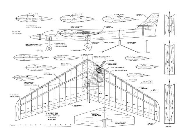
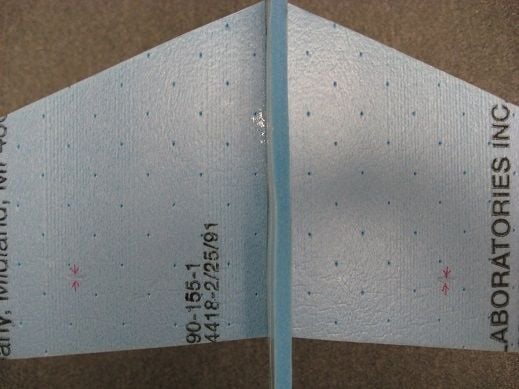
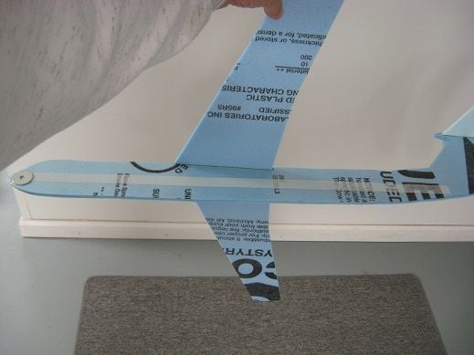
Trouble explaining the concept here; hope this picture will help - this is the design/plan referred to in the opening post.
When viewing the airplane in plan-view, the engine is located offset from the centerline in the leading edge of the right wing. Unfortunately, picture is superimposed over pertinent information on the plan.
 07-05-2018, 05:04 AM
#10
considering the important concept of keeping the control lines taught during flight. as I learned many years ago the lead out should help point the plane away from the circle. so,..as the plane wants to fly away from the circle the lead outs help point it away. all factors,....the belcrank slightly behind the CG and the lead outs positioning the virtual center of the control wires slightly behind the belcrank' s pivot, work to point the plane away from the circle as the control line tension increases. the exact amount is a variable not really established with any concrete factor other than a theoretical approximation of what is minimally required to reliably keep the plane at the ends of the control lines. some amount of this offset is required because of the drag on the lines, which want to turn the plane towards the center of the circle and some of that offset has to be extrapolated into the bow of the lines from drag. the closer this arrangement can be predicted, the smoother the plane will respond to control input. what is given as a suggested arrangement has been established only be trial and error over the many years that large u-control has been flown. the feel of how the plane is pulling on the lines is also a variable and is produced by the combined arrangement of bell crank to CG offset virtual lead out center to belcrank center off set, engine's thrust and rear stabilizer input. everyone has a "feel" they want to recognize as they fly.
Last edited by r ward; 07-05-2018 at 05:06 AM.
07-08-2018, 05:24 PM
#11
Agreed.
As R8893 mentioned and taking into consideration that bellcrank position is not critical, note that in this case, the bellcrank pivot point is actually forward of the CG on Jim Mayfield's Charger shown above probably because moving it any further aft means it would not have room to remain within the confines of the wing profile. Only the single point leadout is aft of the CG.
Figured out and answered my own question/confusion of post #5 here.
08-11-2018, 12:58 PM
#12
Glad to have engineers in on this. In flight, the lines form an accelerated catenary due to their air drag. For the non-math types, a catenary curve is the form of a rope suspended at both ends. Suspension bridges, okay?
But, for that example, the 'load' is simply the 'rope's' weight. Added loads shift the bottom of the sag. Or not, if the expected load is designed for...
The air drag on our flying lines depends on their velocity - actually V^2 - and the drag of their shape. as the model turns one lap, the lines near the handle have practically no velocity. Out at the wingtip they fly the same speed as the model. Instead of a symmetrical sag, the sag grows larger (with the increasing drag load) on the way to the wingtip.
Line pull, at neutral elevator, is balanced between the two lines. You can think of pull as one force acting along the sag as it reaches the leadout guides. Maneuver loads change this only temporarily and the center of pull is still between the two lines.
If you want to reduce friction and bending of the leadouts, this mid-line - at neutral - should point at the bellcrank pivot at the CG and the leadout guides should aim the pull leadouts so they don't rub on the guides. Not totally possible, but we can come close... This is the only benefit of placing the bellcrank pivot at a certain location. We can tolerate some slight rubbing in the guides and bending of flex cable leadouts if we can't fit the bellcrank perfectly.
The sag can be calculated by the line diameter, by how many lines and by the speed at the leadout guides. The pull "axis" between the leadouts at the CG is usually about 3� to 5� behind a right angle line in the fuselage at the CG out towards the inboard wingtip. Having the CG a bit forward of the quarter chord does help keep the nose out.
With modern designs, not much is needed. Excess engine out thrust (angle out from fuselage centerline) can cause problems. Same for excess right rudder (in normal counter clockwise flight.) Too much right yaw is draggy; forces the fuselage out of best alignment to the air it flies through. For a model that should stunt, that can mess up sharp corners.
Hinging? When the rudder and/or leadout to CG conditions - or both - are far off, the model is forced into a definite yaw position. Drag from a sharp turn can pull the lines straight,.rapidly removing the yaw. That moves one wingtip faster and slows the other. Lift also goes by the square of speed, so that causes a big difference in lift between the two halves of the span. The faster panel lifts more; the lower one less. Works like ailerons! CL doesn't (usually) need ailerons.
In a bad hinging situation, fliers have seen the "more lift" wing almost in plan view. If it puts the model that much 'out of shape' (clean and streamlined to the air it flies through) imagine how much it affects stability, controllability and the flier's nerves!
This is usually more problem when trying sharp corners... It really helps to have all the big forces pass through a single point - the fore/aft, spanwise and vertical CG. Then they don't have lever arms around the CG to cause direction changes. Again - impossible to have perfect for all speeds and conditions, but close is very good.
08-11-2018, 01:32 PM
#13
I hope my long note(Post #12) about the curve of the flying lines in flight makes sense. We don't really need the model to actually be yawed away from us! In more or less "normal" flight, the model will pull about 3g. So, a 1.5 lb model will pull 4.5 lb. It is best when the model's fuselage is at a tangent to the flight circle at the CG. Nose and tail aim very slightly outside the flight circle. The fuselage is straight - we hope - and the circle is round. Well duhh...
The term 'leadout rake' just means, that, at best, we have the leadout guides moved aft just enough so that when the curved line of force carried by the lines reaches the wingtip, that direction of pull force aims just about at the CG, If it aims too far forward, it will pull the nose in. Too far back, vice versa, it makes the yaw, relative to the air it the model flies through, excessive, costing speed and usually controllability as well.
Engine offset usually only wastes a small part of thrust. It may affect airflow around the fuselage. Propwash spirals as it moves aft. I use a small amount of offset. If all else is lost, the slight outward fraction of thrust might just get the model back out to the end of the lines before the ground gets to it.
08-12-2018, 01:54 PM
#14
Thanks for continued interest in this thread.
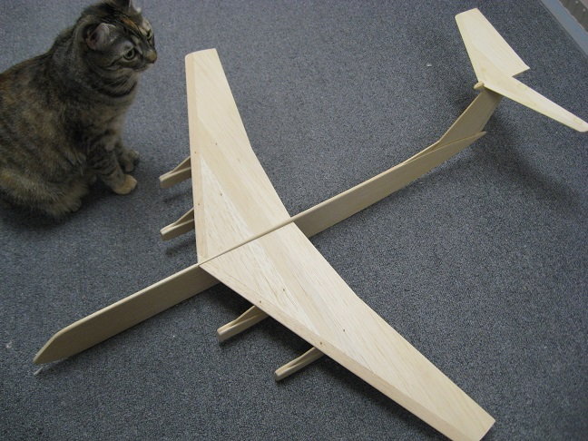
The reason for my opening post is I want to try to complete a modeler's project he gave me before he died. Its a profile Lockheed C-141 Starlifter and may be using Jim Mayfield's design idea. I'm not a trained engineer, so I'm trying to gain as much information as possible to tackle the task. My primary interest is R/C, however, I dabble in C/L on occasion. C/L somehow falls into the progression of interest in aviation for my makeup. Maybe he abandoned it because he thought it wouldn't work well but I want to give it a go. Like someone I know once said - "I know just enough to get me into trouble" so here I am and I appreciate all the help I can get...
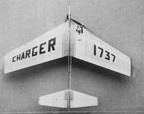
I've started work on it. Located fake engine nacelles to the best of my ability and pinned same to bolster attachment to wing. Followed preliminary wing cut-out noted in fuse to locate wing for (intended?) angle of incidence. Engine to be located between fuse and nacelle #3 - thrust-line normal to LE Like Jim Mayfield's Charger. Thinking vectored thrust here - more line tension than forward motion... Cat included in pic as means of size reference. To be .049 powered. Not sure if elevator should be inboard or outboard - shown inboard here.

The reason for my opening post is I want to try to complete a modeler's project he gave me before he died. Its a profile Lockheed C-141 Starlifter and may be using Jim Mayfield's design idea. I'm not a trained engineer, so I'm trying to gain as much information as possible to tackle the task. My primary interest is R/C, however, I dabble in C/L on occasion. C/L somehow falls into the progression of interest in aviation for my makeup. Maybe he abandoned it because he thought it wouldn't work well but I want to give it a go. Like someone I know once said - "I know just enough to get me into trouble" so here I am and I appreciate all the help I can get...
I've started work on it. Located fake engine nacelles to the best of my ability and pinned same to bolster attachment to wing. Followed preliminary wing cut-out noted in fuse to locate wing for (intended?) angle of incidence. Engine to be located between fuse and nacelle #3 - thrust-line normal to LE Like Jim Mayfield's Charger. Thinking vectored thrust here - more line tension than forward motion... Cat included in pic as means of size reference. To be .049 powered. Not sure if elevator should be inboard or outboard - shown inboard here.
Last edited by H5606; 08-13-2018 at 03:16 AM.
08-12-2018, 03:50 PM
#15
Very nice work!
Looks like 35" to a bit over 40" total span... Close?
4 0.049s will certainly haul a model that size! I presume you intend to mount them on the pods? Possibly sidewinder with heads outboard?
I'd definitely consider good bracing for the pod mountings as well as the engine mounts. Beveled strip about 1/2" on the horizontal and vertical faces should do and it may be under the wing and pretty well hidden by the pods - so not distract in appearance.
Possibly also support the joints from fuse to wing, wing to pods, and fuse to stab & elevator. Lightweight fibreglas or carbon veil work well. Epoxy, scraped to barely damp works well on f/glas. An ordinary playing card, swept gently like trailing a wide broom, shouldn't pull f/glas fibers.
CF is a bit more touchy. Fibers pull out easily. If you still have any clear dope for finishing, a few light coats, thinned half and half, is good prep Let clear dope cure overnight, then sand gently with about 220 grit paper to knock down any grain fuzz. Wipe sanding dust off for the next coat. Careful to not go through to the bare wood when sanding.
Second coat may need only 300+ grit to knock down any fuzz. By this point, f/glas can be laid on the critical areas with that card squeegee method. CF is best attached with either very thinned clear, or straight thinner brushed gently through it to soften the dope surface and adhere it to the wood. When that's dried at least a few hours, a coat of slight less thinned dope will adhere it solidly. A brushed coat of a thinned surface sealer, then careful sanding with fine sandpaper should give a smooth, grain hidden surface for the colors and markings you choose.
As to the geometry of the wing... A bit complicated for here. The idea turns out to be finding the "centroid" of the wing. Fear not! That just means the point at the middle of the area. It can be calculated. It can be found graphically by adding lines to the top view of the wing. Or it can be found by cutting a piece of, say cardboard, to the shape of the wing and finding where that balances lengthwise and spanwise. More later: dinner bell has chimed
08-12-2018, 11:43 PM
#16
.Dinner was great, and the evening wandered way off topic.
At the 'centroid,' the area to the right is the same as the area to the left. A cutout of the wing shape on a uniform weight thing like, say, corrugated cardboard, confirms that. Find its spanwise balance point over a wire or tube. Equal weight when areas are equal.
The C-141's planform is nearly a uniform taper from root to tip. So, the chord at the centroid can give you a base chord to figure a balance point at 20%. On the cutout form, remember the sweep. 20% of the centroid chord, swept as the planform shows, should work as a good balance point for the whole model. A 15% fore and aft CG may be better for a non-maneuverable model.
As mentioned, placing the leadouts so they are centered a few degrees aft of the spanwise line perpendicular to the fuse centerline will cover the curve of the lines from drag.
If this is too thick, or I haven't described it well enough - my apologies...
The stab&elevator are not critical. Check to be sure the horizontal tail area is about 15% of wing area. If not, you could 'fudge' by enlarging it - keeping the proportions - without desecrating the intention.
Left or right side? Shouldn't make any important difference. Theoretically, if it is outboard, it will tend to roll the model right on UP control and left on DOWN. And vice versa.
For this model, there's plenty of power to keep the lines tight, so the lines WILL overcome the rolling tendency either way. (Line pull is significant. Rolling lifts or lowers the leadout guides. Pull, at the drag curve angle at the leadouts, tries to keep a straight line to the CG.)
It's actually simple, but it helps to have it reasonably correct. We can't roll in a few clicks of trim if we need to. We CAN adjust our grip on the handle for most problems, then figure how to adjust balance or control throws, or whatever. The plane has to survive that first flight or no adjustments will help. Remember, four 0.049s is the equivalent of at least a tame .20 engine!
Luck and soft landings!
08-13-2018, 03:30 AM
#17
Thanks for the help.
Please re-read last paragraph of post #14 carefully; trying to stay faithful with designer's intentions to be a single and follow K.I.S.S. principle - not a multi.
Visualize prop arc parallel to starboard LE.
W/S: 32"
Length: 34"
Wing and stab are 1/8"; fuse is 3/16"
Please re-read last paragraph of post #14 carefully; trying to stay faithful with designer's intentions to be a single and follow K.I.S.S. principle - not a multi.
Visualize prop arc parallel to starboard LE.
W/S: 32"
Length: 34"
Wing and stab are 1/8"; fuse is 3/16"
Last edited by H5606; 08-13-2018 at 08:09 AM. Reason: Clarification
08-13-2018, 11:30 AM
#18
Aha!
Sounds good, and the structure looks light enough for a single modern 0.049 or 0.061 to carry.
Think about where the CG will be. It is better for a first flight to be definitely nose-heavy, but too much tends to glide ballistically, not aerodynamically.
Best of luck, and keep us informed if you feel like it.
08-16-2018, 11:32 AM
#19
Another thought: fuel tank location - presuming you'll use a separate tank engine, align the tank relative to the direction of flight... ...NOT to the engine thrust line.
I don't know if an integral tank will feed well, if at all, when mounted behind a shaft turned about 35� out from the direction of flight. (estimated Leading Edge sweepback angle.)
For a separate tank, long accepted guidance is: fuel pickup tube at or near the same height as the jet in the spraybar. If it is a sprinkler, TeeDee type inlet, aim for about the middle of the opening. Simple spraybar (as on Medallions) makes the jet easier to find.
No idea about the integral backplate tanks. If the tank can be adjusted, you can test run to see how it goes. Remember the integral tank's fuel pickup is on the rear surface, and aiming the engine's shaft 'outward' will puddle quite a bit of fuel forward, away from the pickup tube.
Luck and good results!
08-18-2018, 06:51 AM
#20
Another thought: fuel tank location -
No idea about the integral backplate tanks. If the tank can be adjusted, you can test run to see how it goes. Remember the integral tank's fuel pickup is on the rear surface, and aiming the engine's shaft 'outward' will puddle quite a bit of fuel forward, away from the pickup tube.
No idea about the integral backplate tanks. If the tank can be adjusted, you can test run to see how it goes. Remember the integral tank's fuel pickup is on the rear surface, and aiming the engine's shaft 'outward' will puddle quite a bit of fuel forward, away from the pickup tube.
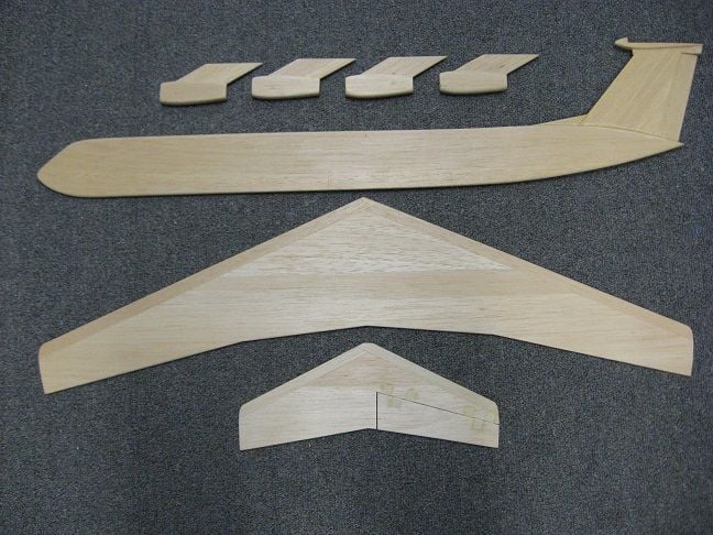
Original plan to bury the engine in the starboard wing root was thwarted by not enough prop clearance between the fuse and the #3 nacelle. Current plan to use a Cox product reedie with backplate tank kit fitted to LE just to get prop out far enough to clear fuse and inboard nacelle. Will try to orient pickup at right fwd position of tank bowl.
I may knock out a foam glider to help determine CG and leadout guide location.
Would like to add removable landing gear for the option of ROG's and hand tosses if it can afford the weight penalty.
Will eventually have questions about finishing since my supply of dope is rather sparse.
Last edited by H5606; 08-18-2018 at 06:59 AM.
09-17-2018, 03:02 PM
#21
Topic has been quiet for about a month, now. Any progress?
I have a lot of magazines with stunt model articles, and many more copies of articles I don't have the mags for. Bulky stuff, the copies help reduce space. Working on it...I found Jim Mayfields CHARGER article!
I hope my description of the curve of the flying lines during flight was not too confusing. Said another way - the lines have their actual weight. The lines mount to the handle and to the model. On the ground, if you hold the handle and a friend holds the model while you pull about as hard as the model does in flight, you can see the gravity sag between those two supports, Sensible?
The lines have air drag in flight, proportional to the square of the airspeed. How fast and how much load? Say you're flying at a 50' radius counting your arm length, the length of the leadouts on the model and the lines themselves. (A bit long but easier numbers.)
The distance around one lap is 2*pi*R or = (2 * 50) * 3.1415 = 314.15 feet.
If you fly a lap in 4.5 seconds, 314.15 / 4.5 = 69.9 ft per second. (60 MPH = 88 ft/sec , so MPH = ft/sec / 1.467. Airspeed = 47+ MPH.
The lines don't have much drag, but at the wingtip they are moving fastest. Their total drag is found from their length and diameter , from how many there are, and the square of the speed. It could be calculated, but it is easier to think of this load as a weight dragging the lines opposite the direction the model is flying. THAT load is NOT the same from the handle out to the model because the airspeed increases from you to it.
That's why the 'trail angle' at the wingtip becomes important. The lines can't apply force except along their length. If the middle point of the leadout guides aims that pull at the (lengthwise) CG, the model will try to fly tangent to the flight circle. If the pull aims ahead of the CG, the CG will try to line up to the pull direction, and tend to pull the nose INTO the circle, and vice versa.
The basic pull force is generated by the model's speed around the circle! Thrust or rudder offsets might help or hurt that. The only certain pull force is "centrifugal." Aiming the model too far nose-in or nose-out creates drag, slows the model - reducing the pull force!
Hinging is related, but different. It is usually seen only on stunt models doing very tight turns. For one example, if the leadouts don't aim pull at the CG because of rudder (and/or engine) offset, a sharp turn requires extra pull to meet the control surfaces airload required. That extra pull tries to line the CG up with the actual direction of pull,. causing a sharp yaw, which slows one wing panel and speeds up the other one. The wings are making greatly increased lift for that turn, so the difference in speeds shows up as roll. There are other factors, like the gyroscope effect of the propeller, which can be very large in tight turns.
Classic hinging is part yaw from where the sharp change of where load aims the pull, and part from the speed difference this yaw causes - the speeded up wing lifts more and the slowed wing less, causing sharp roll.
It's not a happy thing to see your stunter roll and yaw towards you in the middle of a "square" corner. Seldom happens with models that don't fly very tight corner figures.
I enjoyed checking Mayfield's CHARGER article. He says it is VERY sensitive and quick to maneuver. I believe it. We get used to the rate of response with a 3" or larger bellcrank and much longer control horn arms. He used a 2" bellcrank and a tiny elevator control horn. With a handle big enough to fit your hand, ALL inputs get amplified! I believe that we should NOT change the size of these parts because the model is smaller; our hands don't get smaller to match. So, match the hardware to our hands!.
Enjoy!
\LOU
01-01-2019, 02:41 PM
#22
I'm really slow; its in my nature.
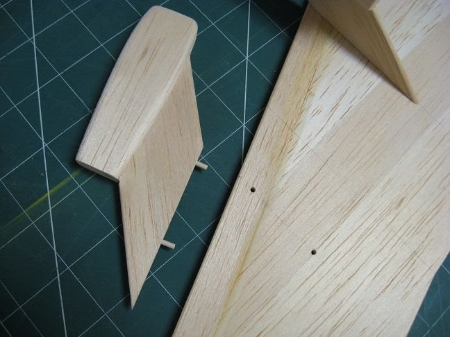
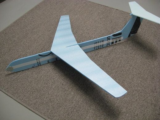
Knocked out the foam glider at scale of 1:1 because it was a no-brainer minus the cosmetic nacelles...
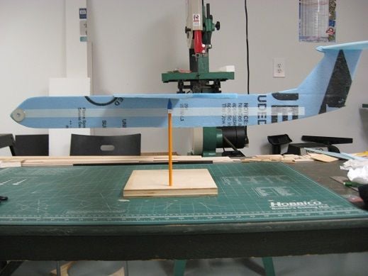
Added nose weight (a single 1/4" fender washer after removing one of two) to get a decent FF glide in the backyard. It seems like it would be really "tail heavy" for C/L. What little I know about model airplane design has me figuring about 50% MAC for FF, 30% MAC for R/C, and maybe 15~20% for C/L. Does this sound like good rule-of-thumb? Advice welcomed.
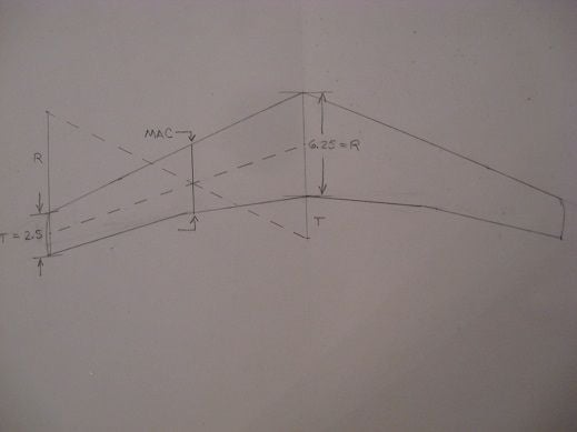
First pic of MAC layout not necessarily to scale (1/2 span is 15 3/4"); last pic shows where leadouts would be with CG as is for C/L (note - as trimmed for free-flight).
What I'd like to know is if I should move the CG way forward for actual control line flight.
Knocked out the foam glider at scale of 1:1 because it was a no-brainer minus the cosmetic nacelles...
Added nose weight (a single 1/4" fender washer after removing one of two) to get a decent FF glide in the backyard. It seems like it would be really "tail heavy" for C/L. What little I know about model airplane design has me figuring about 50% MAC for FF, 30% MAC for R/C, and maybe 15~20% for C/L. Does this sound like good rule-of-thumb? Advice welcomed.
First pic of MAC layout not necessarily to scale (1/2 span is 15 3/4"); last pic shows where leadouts would be with CG as is for C/L (note - as trimmed for free-flight).
What I'd like to know is if I should move the CG way forward for actual control line flight.
