


CK Aero Allure- builders kit build
 12-04-2015, 06:27 PM
#51

Great work on the wings/stabs. Thanks for giving detailed info.
Your wing weights are interesting. I've often wondered how my own foam/balsa wing weights compare to others.
My Magic wings from 2003 are 468 sq. inches, profilm covering, (my favourite as well Ewan) and JR8231 - 49 grams plus linkage.
Ready to fly weight is 427 grams.
Cheers
Scott
Your wing weights are interesting. I've often wondered how my own foam/balsa wing weights compare to others.
My Magic wings from 2003 are 468 sq. inches, profilm covering, (my favourite as well Ewan) and JR8231 - 49 grams plus linkage.
Ready to fly weight is 427 grams.
Cheers
Scott
 12-05-2015, 12:42 PM
#52


Join Date: Sep 2013
Location: New Zealand
Posts: 46
Likes: 0
Received 0 Likes
on
0 Posts
Hi Scott.. I think we are on track using a 45 gram servo , ready to fly weight should be around 365grams .. So it looks like 60-70 gram / panel lighter than the Allure composite wing panel ��
12-05-2015, 02:10 PM
#53
Yeah, composite wings do tend o be a bit heavier, but painted looks nice.
I'm currently using 9411's which are 38 grams flying YS. Being electric without the vibration, I would have thought you could possibly use a bit lighter servo?? Well that's the impression I get anyway.
I look forward to seeing it at the Masters.
I'm currently using 9411's which are 38 grams flying YS. Being electric without the vibration, I would have thought you could possibly use a bit lighter servo?? Well that's the impression I get anyway.
I look forward to seeing it at the Masters.
12-06-2015, 01:00 AM
#54
Member
Thread Starter
Join Date: Apr 2007
Location: TakapauSHB, NEW ZEALAND
Posts: 67
Likes: 0
Received 0 Likes
on
0 Posts
Hi Scott,
Across all disaplines (inc IMAC and Glider) composites do tend to be a bit heavier but they are more repeatable as per design.
I think our efforts from the 2003 really are a base standard for a foam wing, with balsa weights around 13gms a sheet and 30gms of resin to stick them on. Not hard to get it wrong, there is plenty of balsa around at twice that weight and you have added another 80gms. Light weight requires attention to detail until the last servo screw is in.
See you at the Masters
Ewan
12-09-2015, 12:31 AM
#55
Member
Thread Starter
Join Date: Apr 2007
Location: TakapauSHB, NEW ZEALAND
Posts: 67
Likes: 0
Received 0 Likes
on
0 Posts
This builders came without the wing tube installed and I prefer it that way. The wing fillets dictate exactly where the wing will go, the wing incidence well established with a lot of testing. I cut the tube and incidence pin holes using the root ribs in the early stages of wing construction. I have enlarged the wing tube hole to take the sleeve with the ability to fine tune the wing fit (it was very close). I chose to use a slightly larger piece of lite ply in place of the laser cut parts supplied for the tube and wing retaining bolt hard point, This ties this part if the structure together well.
Note the serial number on the label. Ewan
Ewan
Note the serial number on the label.
12-11-2015, 10:48 PM
#56
Member
Thread Starter
Join Date: Apr 2007
Location: TakapauSHB, NEW ZEALAND
Posts: 67
Likes: 0
Received 0 Likes
on
0 Posts
Tube alignment.
Aligning the wing and tail tubes can be one of the most stressful parts of a build if a random approach is taken to it. The method shown here will only work if the tube sleeves in the wing and tail are fitted accurately. Previous postings have shown the ribs for the tailplanes made as identical pairs inner and outer with the tops marked prior to cutting the sleeve hole with the foam bow. This method works equally well for the wing ribs when they are made from lite ply but I did use a pair of master ribs for the hole cutting process.
It is best to fit the wing tube in the fuselage first. This went in easily as the root fillets on the fuselage molding were accurate and I had previously used the rib master to mark out the hole in the fuselage.
Setting the tail tube really does dictate the alignment of the wing and tail.
The bench the fuselage is sitting on has been marked out with a fuselage C/L and some lines at right angles below the tail tube (and a few from the past for wing tubes). The cradle the wing tube is on, has sides that were prepared as a pair so the wing tube is parallel to the bench. I had a similar cradle for the tail tube(temporarily lost) but the plastic bucket did the job.
A simple case of setting the fuselage over the C/L and the tail tube over it's line. Visually check from the rear and commit !!!!

 Ewan
Ewan
Aligning the wing and tail tubes can be one of the most stressful parts of a build if a random approach is taken to it. The method shown here will only work if the tube sleeves in the wing and tail are fitted accurately. Previous postings have shown the ribs for the tailplanes made as identical pairs inner and outer with the tops marked prior to cutting the sleeve hole with the foam bow. This method works equally well for the wing ribs when they are made from lite ply but I did use a pair of master ribs for the hole cutting process.
It is best to fit the wing tube in the fuselage first. This went in easily as the root fillets on the fuselage molding were accurate and I had previously used the rib master to mark out the hole in the fuselage.
Setting the tail tube really does dictate the alignment of the wing and tail.
The bench the fuselage is sitting on has been marked out with a fuselage C/L and some lines at right angles below the tail tube (and a few from the past for wing tubes). The cradle the wing tube is on, has sides that were prepared as a pair so the wing tube is parallel to the bench. I had a similar cradle for the tail tube(temporarily lost) but the plastic bucket did the job.
A simple case of setting the fuselage over the C/L and the tail tube over it's line. Visually check from the rear and commit !!!!
12-13-2015, 12:51 AM
#57
Member
Thread Starter
Join Date: Apr 2007
Location: TakapauSHB, NEW ZEALAND
Posts: 67
Likes: 0
Received 0 Likes
on
0 Posts
The tailplanes are now on complete with the mounting bolts. Really happy with the alignment. Retaining bolt is M3 (the coarser 4-40 would be good but this is a metric aeroplane) and this is taped into a nylon bung loctited into the tail tube, Use a taper tap and it will act as a nylock for the bolt
The 1/32 ply disc is for rod retention on the front pin as there is an adjuster in the tailplane and no stopper beyond it. The disc only is cyanod and the rod will come out if needed.


The photo of the drill press shows drilling the second retaining bolt in the tube, using a long bolt in the first hole to get both of them parallel.
Ewan
The 1/32 ply disc is for rod retention on the front pin as there is an adjuster in the tailplane and no stopper beyond it. The disc only is cyanod and the rod will come out if needed.
The photo of the drill press shows drilling the second retaining bolt in the tube, using a long bolt in the first hole to get both of them parallel.
Ewan
12-16-2015, 12:09 AM
#58
Member
Thread Starter
Join Date: Apr 2007
Location: TakapauSHB, NEW ZEALAND
Posts: 67
Likes: 0
Received 0 Likes
on
0 Posts
Composites.
The following photos show making a new battery and rudder servo trays. At 10gms the rudder servo tray is OK for weight but needs some stiffening, a couple of balsa, ply or carbon tube rails under it would do a good job. The battery tray is similar design to the ones we have been using and have proven to be light and strong.
Both units have been made from 3mm Rohacell 51 foam board, 4mm carbon tube and a layer each side of 200gm (6 oze) carbon cloth laid with the weave at +/- 45deg. The lightening holes could have been cut in after the resin was hard.
The process was to wet the first layer of cloth onto a flat board that had waxed mylar on it. Place the components on it and then the top layer of cloth. Wet it down thoroughly with an excess of resin, the surplus will be taken out in the vac bag / resin extraction process.
Peel ply on next which is has the texture of parker nylon but it lets the resin through. Perforated release film can also be used which is plastic with punched holes.


Soak cloth to absorb the excess resin. I usually buy it from the fabric shop. The whole lot in a plastic freezer bag, cable tied at the neck around the vacuum line. Note handy towel over the end of the vac line that is draped over the soak cloth to give the air a path to track.


The original ply servo tray that needed strengthening was 10gms, the carbon was 12gms and it is extremely rigid (but it looks good). It could be made lighter with lighter cloth.
The original battery tray was 25gms, the carbon one was 16, a useful saving.
Releasing composite components from a mold or vac bag is rather like being a little kid opening Christmas presents, the excitement never really goes away.
Ewan
The following photos show making a new battery and rudder servo trays. At 10gms the rudder servo tray is OK for weight but needs some stiffening, a couple of balsa, ply or carbon tube rails under it would do a good job. The battery tray is similar design to the ones we have been using and have proven to be light and strong.
Both units have been made from 3mm Rohacell 51 foam board, 4mm carbon tube and a layer each side of 200gm (6 oze) carbon cloth laid with the weave at +/- 45deg. The lightening holes could have been cut in after the resin was hard.
The process was to wet the first layer of cloth onto a flat board that had waxed mylar on it. Place the components on it and then the top layer of cloth. Wet it down thoroughly with an excess of resin, the surplus will be taken out in the vac bag / resin extraction process.
Peel ply on next which is has the texture of parker nylon but it lets the resin through. Perforated release film can also be used which is plastic with punched holes.
Soak cloth to absorb the excess resin. I usually buy it from the fabric shop. The whole lot in a plastic freezer bag, cable tied at the neck around the vacuum line. Note handy towel over the end of the vac line that is draped over the soak cloth to give the air a path to track.
The original ply servo tray that needed strengthening was 10gms, the carbon was 12gms and it is extremely rigid (but it looks good). It could be made lighter with lighter cloth.
The original battery tray was 25gms, the carbon one was 16, a useful saving.
Releasing composite components from a mold or vac bag is rather like being a little kid opening Christmas presents, the excitement never really goes away.
Ewan
12-16-2015, 08:16 PM
#59
Member
Thread Starter
Join Date: Apr 2007
Location: TakapauSHB, NEW ZEALAND
Posts: 67
Likes: 0
Received 0 Likes
on
0 Posts
Cut out the control horns for ailerons and elevators. Now is a good time to cut the slots in the surfaces before filming. Photo shows drilling a series of holes in the drill press with the elevator sitting on its shuck to keep the horn square to the surface. Not hard to clean up the hole with a knife and slotting hook.

 Ewan
Ewan
12-20-2015, 05:35 PM
#60
Member
Thread Starter
Join Date: Apr 2007
Location: TakapauSHB, NEW ZEALAND
Posts: 67
Likes: 0
Received 0 Likes
on
0 Posts
Anti rotation pins.
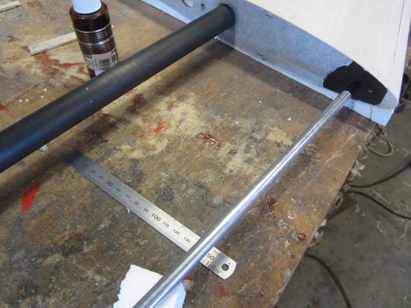
These must be parallel to the wing tube. 12mm balsa hard points are already behind the composite rib, these were fitted in the early stages of wing construction and have been predrilled 8mm. It was only a case of opening the hole out a bit to get alignment. Pins are 8mm carbon tube and have been 24hr epoxied into the balsa leaving the rib without glue. An ali rod turned to fit the inside of the tube helps alignment by measurement and sighting against the wing tube. Wick some thin cyano into the rib and pin joint and leave the epoxy to cure.
 Ewan
Ewan
These must be parallel to the wing tube. 12mm balsa hard points are already behind the composite rib, these were fitted in the early stages of wing construction and have been predrilled 8mm. It was only a case of opening the hole out a bit to get alignment. Pins are 8mm carbon tube and have been 24hr epoxied into the balsa leaving the rib without glue. An ali rod turned to fit the inside of the tube helps alignment by measurement and sighting against the wing tube. Wick some thin cyano into the rib and pin joint and leave the epoxy to cure.
12-26-2015, 01:32 PM
#61
Member
Thread Starter
Join Date: Apr 2007
Location: TakapauSHB, NEW ZEALAND
Posts: 67
Likes: 0
Received 0 Likes
on
0 Posts
Incidence adjusters.
I have put incidence adjusters on both wing and tailplanes as this provides more trimming options later on. The rear wing adjuster is the 8mm Gator product. It is also marketed as an adjuster for boats. The adjuster bolt is M3X0.5 pitch giving 3 turns per degree incidence. The front adjuster is from 1.5mm glass fiber board.


This completes the wing and tail construction. The wings average 250gms and the tailplanes 67.
Ewan
I have put incidence adjusters on both wing and tailplanes as this provides more trimming options later on. The rear wing adjuster is the 8mm Gator product. It is also marketed as an adjuster for boats. The adjuster bolt is M3X0.5 pitch giving 3 turns per degree incidence. The front adjuster is from 1.5mm glass fiber board.
This completes the wing and tail construction. The wings average 250gms and the tailplanes 67.
Ewan
12-30-2015, 12:59 AM
#62
Member
Thread Starter
Join Date: Apr 2007
Location: TakapauSHB, NEW ZEALAND
Posts: 67
Likes: 0
Received 0 Likes
on
0 Posts
Engine mounts.
Santa delivered in the first mail after Christmas with a package from Richard Hirst. One item was lightweight heat sink for a Spin 99 speed controller but more about that in a later post, the other was a carbon mounting system for a Pletty Advance. Richard has been making them for a while and this particular version was dimensioned for the Allure. There have been a few sketches and drawings between us and at this stage it looks like it will bolt straight in. I will give you some weights later and Richards contact info.
The fuselage has a carbon engine mounting ring behind the nosering which is about 5mm thick. I made up 6 standoffs 5.3mm long to give the spinner 2mm clearance. Bryan's design intention is that the front face of the spinner ring is the correct thrustline. My assumption that the nosering was constant thickness was astray so I will be doing some careful measuring before a final installation


The rear mount is a neat pushfit over the rear bearing housing. A couple of adjustable tabs securely glued into the fuselage cheek cowls will complete the installation


 Ewan
Ewan
Santa delivered in the first mail after Christmas with a package from Richard Hirst. One item was lightweight heat sink for a Spin 99 speed controller but more about that in a later post, the other was a carbon mounting system for a Pletty Advance. Richard has been making them for a while and this particular version was dimensioned for the Allure. There have been a few sketches and drawings between us and at this stage it looks like it will bolt straight in. I will give you some weights later and Richards contact info.
The fuselage has a carbon engine mounting ring behind the nosering which is about 5mm thick. I made up 6 standoffs 5.3mm long to give the spinner 2mm clearance. Bryan's design intention is that the front face of the spinner ring is the correct thrustline. My assumption that the nosering was constant thickness was astray so I will be doing some careful measuring before a final installation
The rear mount is a neat pushfit over the rear bearing housing. A couple of adjustable tabs securely glued into the fuselage cheek cowls will complete the installation
Last edited by ewan; 12-30-2015 at 09:47 AM. Reason: Photos did not attach, system not happy last night
12-31-2015, 05:43 PM
#63
Member
Thread Starter
Join Date: Apr 2007
Location: TakapauSHB, NEW ZEALAND
Posts: 67
Likes: 0
Received 0 Likes
on
0 Posts
Pletty / Hirst mounts are now in. To correct the variation in nose ring thickness we measured the thickness with a vernier caliper at each mounting bolt hole and adjusted each standoff spacer to fit. 

The tabs on the rear mount are deliberately long by about 1mm to allow for fitting an individual fuselage. It only took a few minutes to center the adjuster bolt in the slot.
Bogging in!
While a spot of thick cyano may be OK for initial positioning a mix of West micro fiber and resin is fairly standard to complete the job. You also need to spread the stress into the fuselage side for minimum weight. My "twist" is a layer of glass cloth (2oze) about 10mm wide cut on the 45deg over the wet micro fiber mix. Cutting the cloth on the 45 is stronger and it rolls into the compound curve better. Use a wet resin mix that is thick enough to hold on the brush. The front face was done through the cooling vent hole.


 Ewan
Ewan
The tabs on the rear mount are deliberately long by about 1mm to allow for fitting an individual fuselage. It only took a few minutes to center the adjuster bolt in the slot.
Bogging in!
While a spot of thick cyano may be OK for initial positioning a mix of West micro fiber and resin is fairly standard to complete the job. You also need to spread the stress into the fuselage side for minimum weight. My "twist" is a layer of glass cloth (2oze) about 10mm wide cut on the 45deg over the wet micro fiber mix. Cutting the cloth on the 45 is stronger and it rolls into the compound curve better. Use a wet resin mix that is thick enough to hold on the brush. The front face was done through the cooling vent hole.
12-31-2015, 11:12 PM
#64

Join Date: Mar 2005
Location: Saffron Walden, UNITED KINGDOM
Posts: 563
Likes: 0
Received 0 Likes
on
0 Posts
I used a similar mounting system to Richard's, on my Invitation/Pletty Advance.
I used a 2mm epoxy/glass front plate, and a 3-4mm ply back stay, onto the rear bearing housing, much like your (more elegant) carbon one.
I found, however, that the sound in flight was a bit "hard", and wished I'd incorporated some form of soft mount at the front as well as the glass plate.
I was able to retrofit a 3mm ply ring bonded onto the front of the glass plate, and that softened the sound somewhat--but I'd like to know what you think of your setup's sound when you've flown it?
01-01-2016, 06:03 PM
#65
Member
Thread Starter
Join Date: Apr 2007
Location: TakapauSHB, NEW ZEALAND
Posts: 67
Likes: 0
Received 0 Likes
on
0 Posts
We have always flown with solid mounted Pletty and OS belt drives. Have seen the belt drive rubber mounted and it sound quite different. All the Pletty /Advance setups have been with the F3a Unlimited mount with the silicone tube around the rear motor casing. The front mount epoxied to a ply ring which was in turn epoxied into the fuselage. Any thrustline changes made with a tapered washer that matched the 6 bolt Pletty housing.
The Hirst mount is really light at 24gms. Our primary aim was to get the thrustline as per Bryans design. The only "Lord" style mounts we had were 7.5mm long, they needed to be around 5mm for the front mount. The easiest rubber mount option is 6 servo type grommets (or the next size up) on the outer ring, along with the brass insert and the spacer bush as needed.
Will comment on the noise when we fly.
3 Allures (factory built) have been flown in NZ in the last 10 days. 3 very happy pilots.
Ewan
01-04-2016, 09:49 AM
#66
Member
Thread Starter
Join Date: Apr 2007
Location: TakapauSHB, NEW ZEALAND
Posts: 67
Likes: 0
Received 0 Likes
on
0 Posts
Spin 99 Lightweight heat sink.
The other gem in the package from Richard Hirst was a light heat sink and mounting board for the Jetti controller. Weight reduction is 29gms.
Easy to fit, peel the Jetti label off the back and undo the 4 screws. The heat sink has a sticky pad on it's base, but it comes off OK and must be stuck onto the new heatsink. This mod has been around for a while now under Australian conditions and is proven to work. Ewan
Ewan
The other gem in the package from Richard Hirst was a light heat sink and mounting board for the Jetti controller. Weight reduction is 29gms.
Easy to fit, peel the Jetti label off the back and undo the 4 screws. The heat sink has a sticky pad on it's base, but it comes off OK and must be stuck onto the new heatsink. This mod has been around for a while now under Australian conditions and is proven to work.
Last edited by ewan; 01-04-2016 at 01:13 PM.
01-06-2016, 12:04 PM
#67
Member
Thread Starter
Join Date: Apr 2007
Location: TakapauSHB, NEW ZEALAND
Posts: 67
Likes: 0
Received 0 Likes
on
0 Posts
I've done plenty of tidy but average film jobs over the years, with all the usual problems associated with film. A few wrinkles in the sun, a few edges that lift, "balsa loc" that shows through no matter how thinly you put it on. I have normally painted fuselages and filmed the wings and tail.
I think a turning point has been the use of "budget hairspray" in preparing the wood as a surfacing and sticking agent. It doesn't affect foam and can be sprayed on thick and allowed to soak into the wood. Allow it to dry for 3 days and the weight gain is about 2gms. The wood grain will stand up but a light final sand with 320 paper gives good filming surface.
Get rid of all the sanding dust, a soft brush and compressed air works, tac rag if you have one that doesn't leave the tac behind. Clean the bench too.
The bench needs good light. I have bubble wrap on one end and a dressmakers self healing cutting board on the other.
A new blade in the modelling knife (break off blade knives are also good). I recently bought a pair of $40 dressmakers scissors dedicated to film, not to be used of anything else, not even paper. I do have a habit of killing scissors on Kevlar.


Photo also shows concept from down loadable files from CK Aero's site and the working card drawings. Filming is under way and I will post more photos as I proceed. Ewan
I think a turning point has been the use of "budget hairspray" in preparing the wood as a surfacing and sticking agent. It doesn't affect foam and can be sprayed on thick and allowed to soak into the wood. Allow it to dry for 3 days and the weight gain is about 2gms. The wood grain will stand up but a light final sand with 320 paper gives good filming surface.
Get rid of all the sanding dust, a soft brush and compressed air works, tac rag if you have one that doesn't leave the tac behind. Clean the bench too.
The bench needs good light. I have bubble wrap on one end and a dressmakers self healing cutting board on the other.
A new blade in the modelling knife (break off blade knives are also good). I recently bought a pair of $40 dressmakers scissors dedicated to film, not to be used of anything else, not even paper. I do have a habit of killing scissors on Kevlar.
Photo also shows concept from down loadable files from CK Aero's site and the working card drawings. Filming is under way and I will post more photos as I proceed. Ewan
01-07-2016, 07:11 PM
#68
Member
Thread Starter
Join Date: Apr 2007
Location: TakapauSHB, NEW ZEALAND
Posts: 67
Likes: 0
Received 0 Likes
on
0 Posts
Filming the wings is now complete, no doubt there will be some graphics added to it in time.
The film has all been applied in pieces trying to maintain a single layer of film where possible with an overlap of 3 to 5mm. The bottom was done first, starting with the trailing edge so there are no exposed edges of film facing the airflow. The ailerons were not hinged during filming, it is a 50 / 50 call with advantages and disadvantages both ways.
With a lot of edges to preserve here are a few film basics.
There are 3 critical temperatures where things happen.
The lowest is the glue melt point. For most films it is around 100 deg C, but by the you put a sock on the iron, you need another 10 deg, a cold day add another 2 deg. The main thing is to find a sweet spot where the glue activates but the film does not shrink. My iron is currently set on 118 deg
The shrinking temperature is higher, without looking at instruction sheets it is up around 135deg. I am running two filming irons, the second one for shrinking is set on max, it is an old dunger and also has a sock on it. I have used a heat gun for shrinking but for this type of job it is better left in the drawer. Heat guns are good for overheating film and effectively burning it, the 3rd critical temperature.
Technique was to lay the critical edge where you want it, hold it in place with a ruler so that only that edge to be heated is exposed. Work your way around all the edges and stick them down. Run the shrinking iron lightly over the baggy bits until they disappear, swap to the cooler sealing iron and iron that bit down. On a larger area only shrink an area 3 or 4 times the size of the iron. Rolling around edges is best done with the hotter iron with care. Good light is essential.
Hobbyking film all the way. It is as good as the established brands.
Weights average 309gms (6gm variation) which is where we want to be.


 Ewan
Ewan
The film has all been applied in pieces trying to maintain a single layer of film where possible with an overlap of 3 to 5mm. The bottom was done first, starting with the trailing edge so there are no exposed edges of film facing the airflow. The ailerons were not hinged during filming, it is a 50 / 50 call with advantages and disadvantages both ways.
With a lot of edges to preserve here are a few film basics.
There are 3 critical temperatures where things happen.
The lowest is the glue melt point. For most films it is around 100 deg C, but by the you put a sock on the iron, you need another 10 deg, a cold day add another 2 deg. The main thing is to find a sweet spot where the glue activates but the film does not shrink. My iron is currently set on 118 deg
The shrinking temperature is higher, without looking at instruction sheets it is up around 135deg. I am running two filming irons, the second one for shrinking is set on max, it is an old dunger and also has a sock on it. I have used a heat gun for shrinking but for this type of job it is better left in the drawer. Heat guns are good for overheating film and effectively burning it, the 3rd critical temperature.
Technique was to lay the critical edge where you want it, hold it in place with a ruler so that only that edge to be heated is exposed.
Hobbyking film all the way. It is as good as the established brands.
Weights average 309gms (6gm variation) which is where we want to be.
Last edited by ewan; 01-07-2016 at 07:51 PM.
01-09-2016, 01:42 AM
#69
Member
Thread Starter
Join Date: Apr 2007
Location: TakapauSHB, NEW ZEALAND
Posts: 67
Likes: 0
Received 0 Likes
on
0 Posts
Tail planes are under way. Same number of pieces in a tail plane as there is in a wing. Definite sequence for the pieces to get the laps the right way. The overlap on the corners of the red squares gives an indication of all the laps between the colours,

 Ewan
Ewan
01-10-2016, 04:08 PM
#70
Member
Thread Starter
Join Date: Apr 2007
Location: TakapauSHB, NEW ZEALAND
Posts: 67
Likes: 0
Received 0 Likes
on
0 Posts
Here are photos of the wing root, hard points can be seen through the carbon.
Film roll around the edge really well. Basic drafting system, a curved piece of card, very sharp knife and a cutting pad.

Tail planes are now filmed, 84gms without servo and linkage.


 Ewan
Ewan
Film roll around the edge really well. Basic drafting system, a curved piece of card, very sharp knife and a cutting pad.
Tail planes are now filmed, 84gms without servo and linkage.
01-10-2016, 10:27 PM
#71
Join Date: Sep 2013
Location: New Zealand
Posts: 46
Likes: 0
Received 0 Likes
on
0 Posts
Here is another photo of Dad with the filming finished.. It looks fantastic! Very proud of the finished product..
 [QU
[QU
OTE=ewan;12159279]Here are photos of the wing root, hard points can be seen through the carbon.
Film roll around the edge really well. Basic drafting system, a curved piece of card, very sharp knife and a cutting pad.
Tail planes are now filmed, 84gms without servo and linkage.
Ewan[/QUOTE]
OTE=ewan;12159279]Here are photos of the wing root, hard points can be seen through the carbon.
Film roll around the edge really well. Basic drafting system, a curved piece of card, very sharp knife and a cutting pad.
Tail planes are now filmed, 84gms without servo and linkage.
01-18-2016, 11:59 AM
#72
Member
Thread Starter
Join Date: Apr 2007
Location: TakapauSHB, NEW ZEALAND
Posts: 67
Likes: 0
Received 0 Likes
on
0 Posts
The build from this point is at about the same stage as a factory built ARF. It can also be the difference between a very average airframe and one that is very special. Attention to detail, don't rush it. If you don't like the ball link, find a better one, the servo you see fitted today may not be the same in a later post. Watch this space.
Rudder pull, pull linkage:
The bolts for the cable ends and the hinge line all need to be in a straight line to get the geometry right for the closed loop. I put a pinhole through the hinge tape for a 75mm long piece of 22 gauge piano wire indicator. Photos show it taped at right angles to the fuselage C/L.
I have used some nice "Gucci" titanium horns supplied from Bryan at CK Aero. I read Jasons set up instructions after the horns so mine are 10mm lower than his photos. His horns are shorter so his cable entry is further back on the fuselage.


I have used a straight edge (balsa) to find the cable entry point and this is just behind the front tail plane pin on a 75 X 75 closed loop.
I opened the entry hole with a rotary cutter, cleaned it up with a needle file for the guide tube, and there was a composite bulkhead just in front of the hole!!! wrong end of the day to sort that one. Photo shows the 3mm long series bit extended with an M3 pushrod. Another tool to keep.


Ewan
Rudder pull, pull linkage:
The bolts for the cable ends and the hinge line all need to be in a straight line to get the geometry right for the closed loop. I put a pinhole through the hinge tape for a 75mm long piece of 22 gauge piano wire indicator. Photos show it taped at right angles to the fuselage C/L.
I have used some nice "Gucci" titanium horns supplied from Bryan at CK Aero. I read Jasons set up instructions after the horns so mine are 10mm lower than his photos. His horns are shorter so his cable entry is further back on the fuselage.
I have used a straight edge (balsa) to find the cable entry point and this is just behind the front tail plane pin on a 75 X 75 closed loop.
I opened the entry hole with a rotary cutter, cleaned it up with a needle file for the guide tube, and there was a composite bulkhead just in front of the hole!!! wrong end of the day to sort that one. Photo shows the 3mm long series bit extended with an M3 pushrod. Another tool to keep.
Ewan
01-19-2016, 12:53 AM
#73
Member
Thread Starter
Join Date: Apr 2007
Location: TakapauSHB, NEW ZEALAND
Posts: 67
Likes: 0
Received 0 Likes
on
0 Posts
Mounted the speed controller on a 3mm Rohacell and 90gm carbon cloth sub bulkhead that sits under the motor at 45deg. Three 12mm square hard points for the mounting bolts from 3mm ply. Weight 6gms. Extra cooling hole under the spinner.

Ewan
Ewan
01-21-2016, 11:26 PM
#75
Member
Thread Starter
Join Date: Apr 2007
Location: TakapauSHB, NEW ZEALAND
Posts: 67
Likes: 0
Received 0 Likes
on
0 Posts
Control surfaces.
Ailerons and elevators have been hinged with CA hinges. Almost too basic to work but they do work well. Hardest task is cutting the hinge slots in the right place. I have had this guide for 20 years and it is constantly accurate. I have marked a top surface as errors add up like the thickness of the knife blade if you use the marked side for the top of the wing and the bottom of the aileron.
Ball links.
We have used Heli ball links on F3a aeroplanes, We weren't happy with the quality of the 2mm ball links we had so Hamish researched the current market and came up with these 700 size links. You do need the tool to get them on and off. Photos show them on a 2.5mm titanium pushrod that Jason sells. They also go on a 2/56 pushrod.


They have an allen key head for tightening.
Ewan
Ailerons and elevators have been hinged with CA hinges. Almost too basic to work but they do work well. Hardest task is cutting the hinge slots in the right place. I have had this guide for 20 years and it is constantly accurate. I have marked a top surface as errors add up like the thickness of the knife blade if you use the marked side for the top of the wing and the bottom of the aileron.
Ball links.
We have used Heli ball links on F3a aeroplanes, We weren't happy with the quality of the 2mm ball links we had so Hamish researched the current market and came up with these 700 size links. You do need the tool to get them on and off. Photos show them on a 2.5mm titanium pushrod that Jason sells. They also go on a 2/56 pushrod.
They have an allen key head for tightening.
Ewan

