


The Handley Page HP115
 12-14-2015, 04:35 AM
#1

Thread Starter
It seems odd now but in the early 1950s the UK aircraft industry and RAE Farnborough in particular were amongst the world leaders in supersonic research.
It was quickly recognised that the only way to achieve any sort of efficiency at super sonic speeds was to keep the airframe within the shock wave which meant a small wing span and thus high landing speeds.
One theoretical solution to the problem of achieving sustained Mach 2 super sonic flight and have a reasonable landing speed was to use a highly swept delta.
In the days before computer simulations from wind tunnel tests the quickest way was to actually build something and test it so the HP115 was ordered.

At 72 degrees it had (and still is!) the most highly swept delta flown.
Very subsonic (fixed under carriage!) I reasoned it would make an 'interesting' EDF.
Unfortunately as it used a tiny Viper turbo jet it also had very modest size inlet.
Could it be built light enough to fly with scale size ducts?
It was quickly recognised that the only way to achieve any sort of efficiency at super sonic speeds was to keep the airframe within the shock wave which meant a small wing span and thus high landing speeds.
One theoretical solution to the problem of achieving sustained Mach 2 super sonic flight and have a reasonable landing speed was to use a highly swept delta.
In the days before computer simulations from wind tunnel tests the quickest way was to actually build something and test it so the HP115 was ordered.
At 72 degrees it had (and still is!) the most highly swept delta flown.
Very subsonic (fixed under carriage!) I reasoned it would make an 'interesting' EDF.
Unfortunately as it used a tiny Viper turbo jet it also had very modest size inlet.
Could it be built light enough to fly with scale size ducts?
 12-15-2015, 02:52 PM
#2
Thread Starter
Clearly it was going to have to be very light and with such a limited span it was likely to be plenty strong enough using just a Depron skin over a Depron frame work with no other reinforcing required.
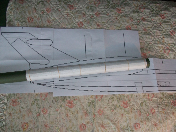
First a decent three view with all the formers generated.

The side view 'tile' printed to the required size. That is a 24" steel rule.

The bulk of the originals fuselage was built around a box girder so this would be done the same way.

Although built in just 2mm Depron it contained quite a bit of Depron that would add little strength so each side panel was heavily cut out.

Next is the EDF duct.
First a decent three view with all the formers generated.
The side view 'tile' printed to the required size. That is a 24" steel rule.
The bulk of the originals fuselage was built around a box girder so this would be done the same way.
Although built in just 2mm Depron it contained quite a bit of Depron that would add little strength so each side panel was heavily cut out.
Next is the EDF duct.
12-16-2015, 09:32 AM
#3
Thread Starter
First the top deck of the fuselage is skinned in 2mm Depron which significantly increases the stiffness.

The EDF will be right at the back and 'angled' to the actual inlet duct.

The inner duct is a parallel tube built over a piece of rainwater down pipe.
The formers are threaded over the inner tube and the EDF glued on the back. Note the moulded bell mouth is not used but is retained as it adds to the rigidity of the EDF body.

A Depron bell mouth is created from a ring of 6mm Depron. at the front.

Finally the outer surface is planked in 2mm Depron.

At this stage the whole duct is just resting on the fuselage 'box' so it can be 'adjusted' to fit correctly. A good over all fit is important as the whole duct will be simply glued in place.
The EDF will be right at the back and 'angled' to the actual inlet duct.
The inner duct is a parallel tube built over a piece of rainwater down pipe.
The formers are threaded over the inner tube and the EDF glued on the back. Note the moulded bell mouth is not used but is retained as it adds to the rigidity of the EDF body.
A Depron bell mouth is created from a ring of 6mm Depron. at the front.
Finally the outer surface is planked in 2mm Depron.
At this stage the whole duct is just resting on the fuselage 'box' so it can be 'adjusted' to fit correctly. A good over all fit is important as the whole duct will be simply glued in place.
Last edited by Quorneng; 12-17-2015 at 04:44 AM.
12-18-2015, 02:24 AM
#4
Thread Starter
Next is the cockpit section.
As it is heavily double curved it will be built as an all 2mm Depron planked structure using half formers over the plan.
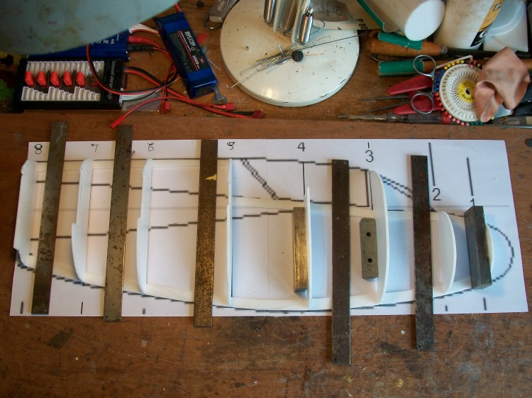
The first few planks.

Once sufficient area is covered the structure is rigid enough to be lifted from the plan and the other half of the formers added.

The battery box is built into cockpit.

There are now 3 separate pieces.

Although the cockpit section will be simply glued onto the front of the fuselage 'box' note the wing structure significantly overlaps the join adding considerable strength.
As it is heavily double curved it will be built as an all 2mm Depron planked structure using half formers over the plan.
The first few planks.
Once sufficient area is covered the structure is rigid enough to be lifted from the plan and the other half of the formers added.
The battery box is built into cockpit.
There are now 3 separate pieces.
Although the cockpit section will be simply glued onto the front of the fuselage 'box' note the wing structure significantly overlaps the join adding considerable strength.
Last edited by Quorneng; 12-18-2015 at 02:26 AM.
12-21-2015, 11:26 AM
#5
Thread Starter
The wings are a surprisingly complex shape.
Yes a simple delta in plan and fully symmetrical in section but it is not the same section root to tip. It is proportionally much thicker at the root than the tip. This means the wing has significant double curvature and thus cannot be covered by a single sheet.

First the nose is glued onto the front of the box spine and the Depron wing 'formers' added. There are no spars as such all the strength and stiffness will come from the 2 mm Depron skin.

The wing is in effect covered in a series of fore and aft tapered planks.

The wings fully skinned.

A small 2x1 mm strip of hard balsa is glued along the leading edge to provide a bit of 'ding' resistance.
The elevons are fully built up and are huge.

Each ending up as a remarkably stiff triangular box.

Each elevon is tape top hinged.
Yes a simple delta in plan and fully symmetrical in section but it is not the same section root to tip. It is proportionally much thicker at the root than the tip. This means the wing has significant double curvature and thus cannot be covered by a single sheet.
First the nose is glued onto the front of the box spine and the Depron wing 'formers' added. There are no spars as such all the strength and stiffness will come from the 2 mm Depron skin.
The wing is in effect covered in a series of fore and aft tapered planks.
The wings fully skinned.
A small 2x1 mm strip of hard balsa is glued along the leading edge to provide a bit of 'ding' resistance.
The elevons are fully built up and are huge.
Each ending up as a remarkably stiff triangular box.
Each elevon is tape top hinged.
12-23-2015, 12:32 PM
#6
Thread Starter
As I fly from a rather rough grass field it would be flown hand launch/belly land.
This posed a problem with the elevon horns which unless mounted on the upper surface would 'catch' badly on landing.
A rather unusual solution was to bury the servo as low as possible in the fuselage box and use a very short vertical link to the aileron.

This solution has the advantage that it gives a 2:1 mechanical advantage to the servo yet is virtually completely buried.

As the motor is a long way from the battery it uses solid copper 'magnet' wire to save the not inconsiderable weight of the normal silicon insulation.

The wires run forward under the top of the fuselage to the ESC just behind the cockpit.

The ESC is set do the tips of its 'fingered' heat sink are just in the air stream.
As it as a 'bank and yank' the fin is built in one piece and mounted on top of the duct.

With all the parts glued together a top view does show just how 'steep' the delta is.

Not much more to do.
This posed a problem with the elevon horns which unless mounted on the upper surface would 'catch' badly on landing.
A rather unusual solution was to bury the servo as low as possible in the fuselage box and use a very short vertical link to the aileron.
This solution has the advantage that it gives a 2:1 mechanical advantage to the servo yet is virtually completely buried.
As the motor is a long way from the battery it uses solid copper 'magnet' wire to save the not inconsiderable weight of the normal silicon insulation.
The wires run forward under the top of the fuselage to the ESC just behind the cockpit.
The ESC is set do the tips of its 'fingered' heat sink are just in the air stream.
As it as a 'bank and yank' the fin is built in one piece and mounted on top of the duct.
With all the parts glued together a top view does show just how 'steep' the delta is.
Not much more to do.
12-26-2015, 04:28 PM
#7
Thread Starter
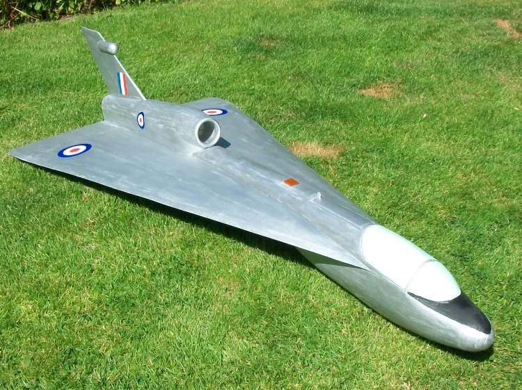
Due to the weather I decided to paint in before its maiden. simple as it is silver all over!

The battery goes in under the scale cockpit canopy with the finned ESC heat sink just behind.
Being a simple delta working out a suitable CofG was not to hard but I found that with the 1800mAh 3s in the cockpit it was much too nose heavy. The battery was going to have to go behind the cockpit
This meant quite a major re work was going to be required and it had not even flown!
This shows how far the ESC had t be moved back.

The cockpit could now be completely rebuilt with a fixed canopy.

The solid canopy is actually part of the fuselage skin and is fully load bearing.
The new battery and ESC positions complete.

It was now ready to go.
Which it does although just like the full size it has a relatively 'modest' performance.
https://www.youtube.com/watch?v=vP7TFM7sFo0 Talk about 'ground effect' on landing!
The battery goes in under the scale cockpit canopy with the finned ESC heat sink just behind.
Being a simple delta working out a suitable CofG was not to hard but I found that with the 1800mAh 3s in the cockpit it was much too nose heavy. The battery was going to have to go behind the cockpit
This meant quite a major re work was going to be required and it had not even flown!
This shows how far the ESC had t be moved back.
The cockpit could now be completely rebuilt with a fixed canopy.
The solid canopy is actually part of the fuselage skin and is fully load bearing.
The new battery and ESC positions complete.
It was now ready to go.
Which it does although just like the full size it has a relatively 'modest' performance.
https://www.youtube.com/watch?v=vP7TFM7sFo0 Talk about 'ground effect' on landing!
