


Electronic solutions to modifying glow engines of all sizes to gasoline


 11-21-2022, 11:34 AM
#1177


That 100 hour life cycle, I would suspect if the pump is run at full duty cycle, but since it will be modulated, the life expectancy should be extended... only unknown is how the pump membrane will hold up to the fuel vapors... I like the idea, it gets rid of the crap trap, and the size of the package is small enough to take the place of the trap bottle... Will that pump move liquids as well, could be used as a fuel pump, but the pump membrane is the only issue whether is will hold up to the fuel.
11-21-2022, 03:16 PM
#1178
John,
I'm sure the membrane is silicone type material so wouldn't stand up well to fuel (other than glow) The fuel vapour is not an issue as the outlet check works very well and vapour can't be pushed back through the pump. Even when filling the tank it is forced to vent through the "bleed" that is provided by the needle valve in the current setup - Im working on a simplified bleed "tee" that is just an orfice - just have to determine the size.
I'm sure the membrane is silicone type material so wouldn't stand up well to fuel (other than glow) The fuel vapour is not an issue as the outlet check works very well and vapour can't be pushed back through the pump. Even when filling the tank it is forced to vent through the "bleed" that is provided by the needle valve in the current setup - Im working on a simplified bleed "tee" that is just an orfice - just have to determine the size.
11-21-2022, 07:14 PM
#1179
Ok, whats the check valve made of?...
Some silicone formulas are resistant to petroleum / gasoline... if that pump was intended for medical use, it probably has a food grade silicone membrane... its a shame there isn't a small inexpensive fuel pump about the same size... then you could just modulate the fuel pressure, and leave the fuel tank vented to the atmosphere... it would only require a small change in fuel pressure to mimic muffler tank pressure.
Some silicone formulas are resistant to petroleum / gasoline... if that pump was intended for medical use, it probably has a food grade silicone membrane... its a shame there isn't a small inexpensive fuel pump about the same size... then you could just modulate the fuel pressure, and leave the fuel tank vented to the atmosphere... it would only require a small change in fuel pressure to mimic muffler tank pressure.
11-21-2022, 08:09 PM
#1180
I suspect the pump check is a membrane type silicone valve also - I will pull one apart to have a better look but I have attached a drawing and specs - They are a positive displacement pump with two tiny pistons that operate on an eccentric. They are definitely PD as if you plug the outlet it will stall the pump. I think that's why they are working well here as speed is very linear to output . They do make them for moving water but I suspect they are not up to "chemical" use - maybe glow fuel? When I get my cheap ones from overseas I will sacrifice one for the cause. Im using Amazon supplied ones right now and they are $10 a pop (vs $1.50 direct)
https://www.maxcleversz.com/html_pro...r-pump-94.html
https://www.maxcleversz.com/html_pro...r-pump-94.html
11-22-2022, 12:12 AM
#1181
So it looks like both those nipples are air outlets?, so the pistons alternate back and forth, where is the air inlet?... That drawing isn't very clear 
***EDIT***
This model has only one air outlet, but the url still refers to it as a double-outlets ( Chinese nomenclature") ) neither models are clear where the air inlet is, unless its that unmarked hole next to one of the nipples... not that it matters, I just like to know where the air inlet is.
) neither models are clear where the air inlet is, unless its that unmarked hole next to one of the nipples... not that it matters, I just like to know where the air inlet is.
https://www.maxcleversz.com/html_pro...r-pump-93.html
***EDIT***
This model has only one air outlet, but the url still refers to it as a double-outlets ( Chinese nomenclature
) neither models are clear where the air inlet is, unless its that unmarked hole next to one of the nipples... not that it matters, I just like to know where the air inlet is.https://www.maxcleversz.com/html_pro...r-pump-93.html
Last edited by John_M_; 11-22-2022 at 12:41 AM.
11-22-2022, 07:26 PM
#1182
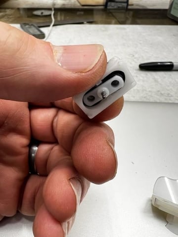
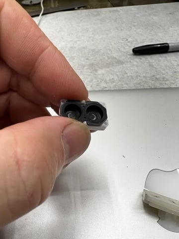
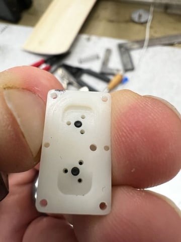
Took one apart - Curiosity killed the cat!!! the thing is actually a twin with two cylinders and two sets of valving - the top is a trick with porting as the middle port is the outlet and the side one is an inlet that ports around and under the pistons. The intake valves are on the tops of the plastic pistons which are captured in a loose fitting membrane seal. A small angular shaft eccentric makes the piston assembly oscillate as an opposed pair. There is a valve in each cylinder and they port to the outlet nipple. Actually a neat little design and they are very efficient for power input to air delivery.
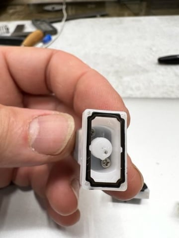
here is a video of it in action..
here is a video of it in action..
11-22-2022, 08:46 PM
#1183
Interesting, they show the dual nipples version as both nipples being separate outlets, one for each membrane piston... the single nipples version has double the flow rate over the twin nipple version, as each membrane piston shares the one common outlet port ... indeed it is a neat little air pump, probably used in COPD oxygen concentration medical devices... I can see that lasting longer than 100 hours, most likely the motor has brushes, which has a limited life span.
11-23-2022, 04:25 AM
#1184
Most likely it has a longer lifespan than 100 hours but it's been rated at 100 hours to reduce failures to a very low number because it's for use in a medical device. I bet it lasts longer than 100 hours with a reasonable safety factor.
11-23-2022, 08:54 AM
#1186
11-23-2022, 09:37 AM
#1187
BTW, I had a miner set back on modifying the walbro to fit the solenoid valve... turns out the Hi/Lo needle spacing is just a bit wider than the solenoid, so the solenoid won't seal in the bore due to the two channels left from the remnants of the original needle ports, one either side of the solenoid bore hole... so I buggered up the first attempt... second attempt, I'm over boring the hole and then press fitting a brass insert to fit the solenoid into.
Thats the only hurdle, not as straight forward as I hoped... then plugging the original Hi/Lo needle fuel feed ports from the metering chamber is easy to do... and then all I need to do is re-drill one feed port from the metering chamber into the solenoid chamber... just need to drill into the chamber at the right height for the inlet to the valve from the side of the carb body, and then cross drill into the metering chamber feed, and then fit a couple plugs to seal off the cross drill holes... Its not an easy DIY, but once its done, the carb body itself should last for quite a while, just have to service the soft parts, diaphragms & seals, etc... it should be worth the effort, I hope.
Thats the only hurdle, not as straight forward as I hoped... then plugging the original Hi/Lo needle fuel feed ports from the metering chamber is easy to do... and then all I need to do is re-drill one feed port from the metering chamber into the solenoid chamber... just need to drill into the chamber at the right height for the inlet to the valve from the side of the carb body, and then cross drill into the metering chamber feed, and then fit a couple plugs to seal off the cross drill holes... Its not an easy DIY, but once its done, the carb body itself should last for quite a while, just have to service the soft parts, diaphragms & seals, etc... it should be worth the effort, I hope.
11-23-2022, 11:33 AM
#1188
Senior Member
Thread Starter
BTW, I had a miner set back on modifying the walbro to fit the solenoid valve... turns out the Hi/Lo needle spacing is just a bit wider than the solenoid, so the solenoid won't seal in the bore due to the two channels left from the remnants of the original needle ports, one either side of the solenoid bore hole... so I buggered up the first attempt... second attempt, I'm over boring the hole and then press fitting a brass insert to fit the solenoid into.
Thats the only hurdle, not as straight forward as I hoped... then plugging the original Hi/Lo needle fuel feed ports from the metering chamber is easy to do... and then all I need to do is re-drill one feed port from the metering chamber into the solenoid chamber... just need to drill into the chamber at the right height for the inlet to the valve from the side of the carb body, and then cross drill into the metering chamber feed, and then fit a couple plugs to seal off the cross drill holes... Its not an easy DIY, but once its done, the carb body itself should last for quite a while, just have to service the soft parts, diaphragms & seals, etc... it should be worth the effort, I hope.
Thats the only hurdle, not as straight forward as I hoped... then plugging the original Hi/Lo needle fuel feed ports from the metering chamber is easy to do... and then all I need to do is re-drill one feed port from the metering chamber into the solenoid chamber... just need to drill into the chamber at the right height for the inlet to the valve from the side of the carb body, and then cross drill into the metering chamber feed, and then fit a couple plugs to seal off the cross drill holes... Its not an easy DIY, but once its done, the carb body itself should last for quite a while, just have to service the soft parts, diaphragms & seals, etc... it should be worth the effort, I hope.
11-23-2022, 11:56 AM
#1189
They can, and I have a couple. If you're worried that these are available for such a low price because they're grey market, I would suggest that Stihl should be manufacturing them in a more secure environment for their intellectual property than china where they are required to share that intellectual property and that if Stihl wants to stop the supply to the grey market they should consider manufacturing them in a more secure environment, like the USA.
11-23-2022, 03:12 PM
#1191
11-23-2022, 03:52 PM
#1192
They can, and I have a couple. If you're worried that these are available for such a low price because they're grey market, I would suggest that Stihl should be manufacturing them in a more secure environment for their intellectual property than china where they are required to share that intellectual property and that if Stihl wants to stop the supply to the grey market they should consider manufacturing them in a more secure environment, like the USA.
 ... the piracy, just raises the retail counter prices to compensate for their losses... its the MFG'er's fault for dealing with these overseas companies.
11-23-2022, 07:40 PM
... the piracy, just raises the retail counter prices to compensate for their losses... its the MFG'er's fault for dealing with these overseas companies.
11-23-2022, 07:40 PM
#1193
I had a chance to reflect a bit as a fellow modeller was in the shop a while back and I was explaining the system to Him and demonstrating it - He is a well rounded modeler with a very good mechanical sense and he was amazed at the system and how well it operated. Its easy to get caught up in it and not realize how good it has become thanks to the "Spark" (pun intended
) provided by a few and the cooperation and sharing of ideas here.
11-24-2022, 03:59 AM
#1195
I'm convinced that how well the temp/pressure compensation works, richening vs. leaning, depends entirely on where the carb needles are set. I mentioned this earlier but didn't get my point across well because of my poor technical communications skills. I'll try again.
In the following example I'm using the phrase "over richen" as meaning the point on the fuel curve where a notable drop in rpm can be detected while moving a curve point upwards (richening) from the stoichiometric center value.
If say the needles are set to where an increase in the curve value of only 10% is required to over richen the mixture, the fixed compensation values for temp/pressure will have X affect on mixture strength. Fine, now, if say the needles are set (leaned) to where an increase in the curve value of 20% is required to over richen the mixture, the fixed compensation values for temp/pressure will have X/2 or 1/2 the affect on mixture strength. Of course this also applies to leaning.
I have found that in attempts to flatten the overall curve using leaner low speed needle adjustments that it is possible to end up having to increase a given curve point value as much as 80% (-100/+100 scale) from the stoichiometric center value to detect an over rich condition. When a needle is pinching off fuel to this degree the solenoid has to be modulated open much longer to supply a given increase in fuel. With the same needle setting it may only take only a 10% (-100/+100 scale) decrease in curve value from the stoichiometric center value to detect an overly lean condition. I'm not sure what to call this condition, "skewing the center line"? "Unbalanced adjustment"? Not sure, but in my thinking that HAS to negatively affect temp/pressure correction.
Intuitively I am now setting the needles to where the % of increase and % of decrease on the curve required to over richen or over lean from the stoichiometric center value are closer to equal. This is not possible to achieve at every point on the curve due to our compensating/overriding the mechanical fuel metering curve ground into our glow carb barrels, however it can be averaged, kind of, across the rpm range. Perhaps adjusted this way, more balanced, the temp/pressure compensation will have the best chance to work properly?
Last edited by Glowgeek; 11-24-2022 at 05:27 AM.
 11-24-2022, 05:32 AM
#1196
I do think we will be limited by "engine cooling" though. Won't the engines inability to warm itself up would interfere with the math calculation based on air density at some point? not really sure how the calculation is done.
11-24-2022, 10:02 AM
#1198
Now what we need is some air time to prove this system out, and unfortunately Old Man winter has found us here - I do try and get out and fly (on ski's) a bit during the winter but its not conducive to experimental work.. more like a survival contest trying to keep digits from freezing. I have to turn my attention to some shop time and get some airframes ready for next spring - Want to have the Boxer and the OS.37 ready on well matched airframes next season. I really find this conversion stuff addicting though and if I wander into the shop with nothing planned I end up tinkering with it most times.
I had a chance to reflect a bit as a fellow modeller was in the shop a while back and I was explaining the system to Him and demonstrating it - He is a well rounded modeler with a very good mechanical sense and he was amazed at the system and how well it operated. Its easy to get caught up in it and not realize how good it has become thanks to the "Spark" (pun intended ) provided by a few and the cooperation and sharing of ideas here.
I had a chance to reflect a bit as a fellow modeller was in the shop a while back and I was explaining the system to Him and demonstrating it - He is a well rounded modeler with a very good mechanical sense and he was amazed at the system and how well it operated. Its easy to get caught up in it and not realize how good it has become thanks to the "Spark" (pun intended
) provided by a few and the cooperation and sharing of ideas here.
65mm x 22mm x 34mm
 11-24-2022, 10:27 AM
#1200
Senior Member
Thread Starter
That is why in the "real world", there are not many fuel injected air cooled engines. Because the engine temperature cannot be properly controlled.