


Electronic solutions to modifying glow engines of all sizes to gasoline
 03-26-2023, 06:06 PM
#1601

Print on paper in a chamber. I have lots of paper and an enclosure. Aside from bed adhesion, it sounds about like printing ASA or abs. I think some glue stick to hold paper on the bed and a good heat soak to get the chamber hot would get it going. For $26 I might just try it.
 03-26-2023, 06:14 PM
#1602

All good, Chris. That last "jet #2" seemed to have a great effect on the bottom end. Now....If you would adjust the hsn to approx +65, as you did on the others, we can get a more apples to apples comparison.
Sorry, don't mean to be difficult, but I NEED a constant to resolve change and effect.
Sorry, don't mean to be difficult, but I NEED a constant to resolve change and effect.

The following users liked this post:
Glowgeek (03-27-2023)
03-26-2023, 06:22 PM
#1603

this could be interesting,
Well on the ft160 i have grinded the slot for the low end of the throttle as you showed me bert..so there would be no side movement of the throttle barrel until near half throttle roughly..basically a set mixture to a degree..
When i ran the engine for awhile..yes i noticed the left cylinder (from behind engine)being rich on idle and 1/4 throttle, probably up to half throttle, it would be noticeably richer than the right cylinder..
when above 1/2 throttle it runs rather even and clean on both cylinders..
could it be something to do with offset cylinders and variations in each intake pipe that causes the fight for even vacuum on each side..
03-26-2023, 06:25 PM
#1604
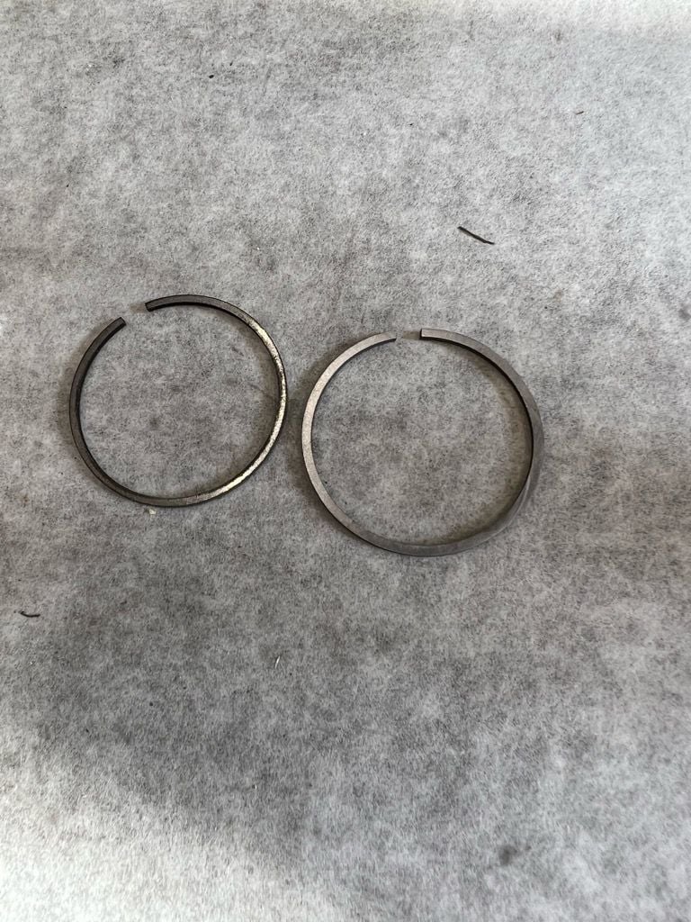
SO... for something a bit different. Im back to getting the boxer ride ready for spring - the one cylinder ( #1) has always seemed a bit flat to me. I did go through everything well and found the valve seat leak issue but sealed those with little change. The rings look to be a little iffy with a bigger than required gap and not a great fit in the piston. Was going to order a set from RMJ but they get expensive coming cross boarder with exchange.. I have made rings before (successfully  ) so I gave to a try for the ASP.. they came out well - Made 2 but only installed one as a Trial. Immediately the engines feels better while cranking even without seating. Will see how this little trial works out.
) so I gave to a try for the ASP.. they came out well - Made 2 but only installed one as a Trial. Immediately the engines feels better while cranking even without seating. Will see how this little trial works out.
The following 3 users liked this post by Cat 1:
03-26-2023, 06:26 PM
#1605
this could be interesting,
Well on the ft160 i have grinded the slot for the low end of the throttle as you showed me bert..so there would be no side movement of the throttle barrel until near half throttle roughly..basically a set mixture to a degree..
When i ran the engine for awhile..yes i noticed the left cylinder (from behind engine)being rich on idle and 1/4 throttle, probably up to half throttle, it would be noticeably richer than the right cylinder..
when above 1/2 throttle it runs rather even and clean on both cylinders..
could it be something to do with offset cylinders and variations in each intake pipe that causes the fight for even vacuum on each side..
Well on the ft160 i have grinded the slot for the low end of the throttle as you showed me bert..so there would be no side movement of the throttle barrel until near half throttle roughly..basically a set mixture to a degree..
When i ran the engine for awhile..yes i noticed the left cylinder (from behind engine)being rich on idle and 1/4 throttle, probably up to half throttle, it would be noticeably richer than the right cylinder..
when above 1/2 throttle it runs rather even and clean on both cylinders..
could it be something to do with offset cylinders and variations in each intake pipe that causes the fight for even vacuum on each side..
03-26-2023, 06:37 PM
#1606
My os ft120-ii with airbleed carb doesn't have a barrel that moves sideways and the cylinders run basically the same. There's probably no difference from front cylinder to back because the fuel doesn't enter the cylinders through the crankcase. I don't believe the cylinder offset makes any difference.
03-26-2023, 06:41 PM
#1607
i understand fuel not coming from the crankcase, but more about slightly different intake tube lengths and possibly the forward cylinder having more vacuum on the intake over the rear cylinder..im not overly fussed on the unevenness, also the engine hasn't had bugger all run time to say its full run in either
By the way, if I start experimenting with printing POM I'm going to have to try printing a solenoid housing too. Still pondering the idea though.
03-26-2023, 06:51 PM
#1608
We'll have you got metal lathe and chris'skills or a 3d printer and a willingness to experiment with it? Like I said, my ft120 twin doesn't suffer from uneven fuel to the cylinders and the only real difference is the carb.
By the way, if I start experimenting with printing POM I'm going to have to try printing a solenoid housing too. Still pondering the idea though.
By the way, if I start experimenting with printing POM I'm going to have to try printing a solenoid housing too. Still pondering the idea though.
into3d printing and so on is beyond my capabilities,
well my engine runs well enough not to worry too much..i have had to put all my stuff in boxes,no more play time for awhile
03-27-2023, 12:53 AM
#1609
Senior Member
Thread Starter
My os ft120-ii with airbleed carb doesn't have a barrel that moves sideways and the cylinders run basically the same. There's probably no difference from front cylinder to back because the fuel doesn't enter the cylinders through the crankcase. I don't believe the cylinder offset makes any difference.
03-27-2023, 02:01 AM
#1610
or maybe cause its not os quality..could be just be a sronger pulse from the front cylinder compared to the rear cylinder on my engine

 03-27-2023, 03:38 AM
#1612
Senior Member
Thread Starter
These things are weird anyway: I can give you this example: in an older airbleed style carb where the NVA basically consists of a needle valve, an orifice and a straight pipe into the venturi throat, leaning the engine to the max on the needle alone (solenoid deactivated) one would think that there is no "headroom" for the solenoid to control mixture. The weird thing is that the "chopping" action of the solenoid promotes evaporation and at around 90~95% solenoid opening (where the chatter of the valve becomes audible) the engine goes rich on less fuel than the "leanest possible" straight through needle setting...
I cannot fully explain what you see here, but at times weird stuff happens...
03-27-2023, 07:27 PM
#1613
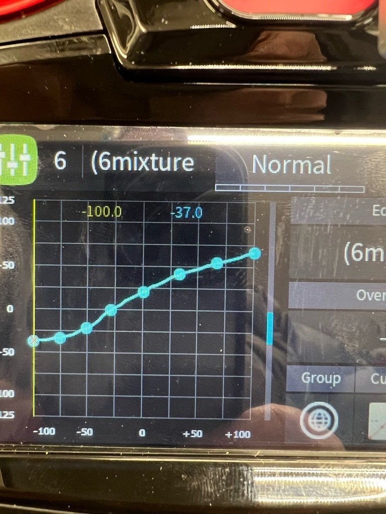
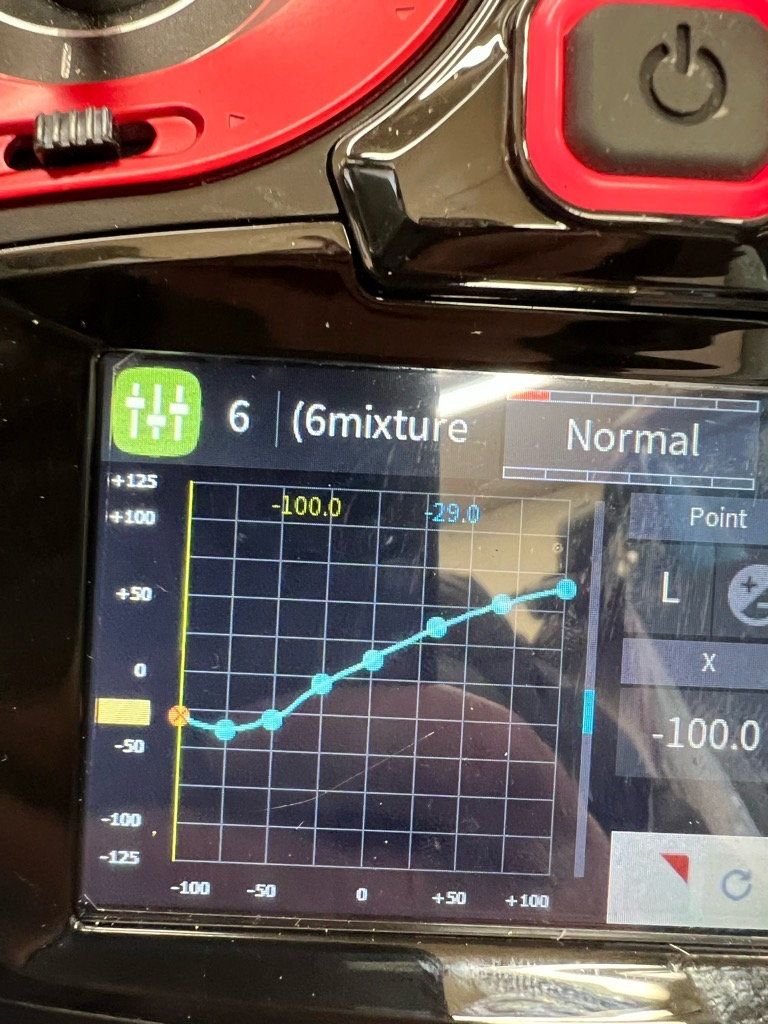
Lonnie... I think I sent too many curves and got us all confused - On the two you sent - The first one was a quick first try and the "straight line curve" did not provide a good "long term" idle.. as it cooled it needed more fuel and to get a reliable idle and acceleration I ended up with the later "big Jet" curve with a pronounced check mark shape - As I went to "small jet" the dip got progressively less and as I closed the HSN to do "your" test it reduced further... I think they responded "typically" as expected and as the dip got less the idle quality improved....
That first Straight line test was misleading as I never spent much time confirming idle... Sorry for the confusion....
That first Straight line test was misleading as I never spent much time confirming idle... Sorry for the confusion....
03-28-2023, 02:30 AM
#1614
No apologies necessary, Chris. I'm keeping track of what works and what doesn't, so I'm paying close attention to developments. A little brain scrambling is a good thing, keeps us on our toes.
Last edited by Glowgeek; 03-28-2023 at 03:20 AM.
03-28-2023, 06:00 AM
#1616
Senior Member
Thread Starter
One thing I dare say from experience, is that the lowest achievable idle on the ground is NOT the lowest achievable idle in the air.
It is possible to idle lower in the air (which makes landing easier in some cases) while still maintaining a 100% reliable throttle response. I am not sure how this works, but it is something I found to be invariably true.
So nowadays I do not sweat it if I cannot get a reliable idle below 3K, I try to get it as low as possible, and then I just go fly, and in the air trim the idle back to 2500 (just using the trim) which is low enough for any plane I know to land safely and comfortably.
On the ground, I keep the engine at 3K with the throttle. No big deal.
It is of course possible to link this raised idle to a switch, but switches can be forgotten after take off, and I prefer an engine that requires a bit attention on the ground over a plane that overshoots the runway due to a higher than expected idle.
After all, as Herr Uli Streich (of Vario Helicopters fame) once said: Carb settings on the starting table are irrelevant, carb settings in the air are all that matter. Now if a helicopter guy (most depending on a safe working engine in the entire aeronautical discipline) says that, then I tend to believe him...
Last edited by 1967brutus; 03-28-2023 at 06:09 AM.
03-28-2023, 05:47 PM
#1617
True: different engines handle different solutions better or worse. There seems to be a trendline for general lay-outs of engines, but no rock-solid science yet.
One thing I dare say from experience, is that the lowest achievable idle on the ground is NOT the lowest achievable idle in the air.
It is possible to idle lower in the air (which makes landing easier in some cases) while still maintaining a 100% reliable throttle response. I am not sure how this works, but it is something I found to be invariably true.
So nowadays I do not sweat it if I cannot get a reliable idle below 3K, I try to get it as low as possible, and then I just go fly, and in the air trim the idle back to 2500 (just using the trim) which is low enough for any plane I know to land safely and comfortably.
On the ground, I keep the engine at 3K with the throttle. No big deal.
It is of course possible to link this raised idle to a switch, but switches can be forgotten after take off, and I prefer an engine that requires a bit attention on the ground over a plane that overshoots the runway due to a higher than expected idle.
After all, as Herr Uli Streich (of Vario Helicopters fame) once said: Carb settings on the starting table are irrelevant, carb settings in the air are all that matter. Now if a helicopter guy (most depending on a safe working engine in the entire aeronautical discipline) says that, then I tend to believe him...
I tend to agree with this idle analogy Bert... When flying nitro I always end up with an idle you have to baby a bit on the ground - makes for a nice low approach idle if needed. I put it to the loading of static vs Being "driven " by airflow but maybe its not that simple.. An off idle stumble on the ground often disappears in the air.. I do love the sound of a sub normal idle on the ground but would trade that anyway for a clean power band from 1/3 to WOT...
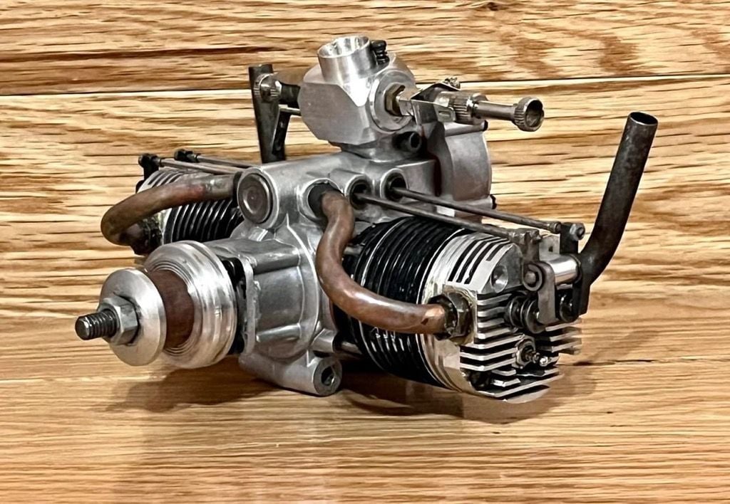
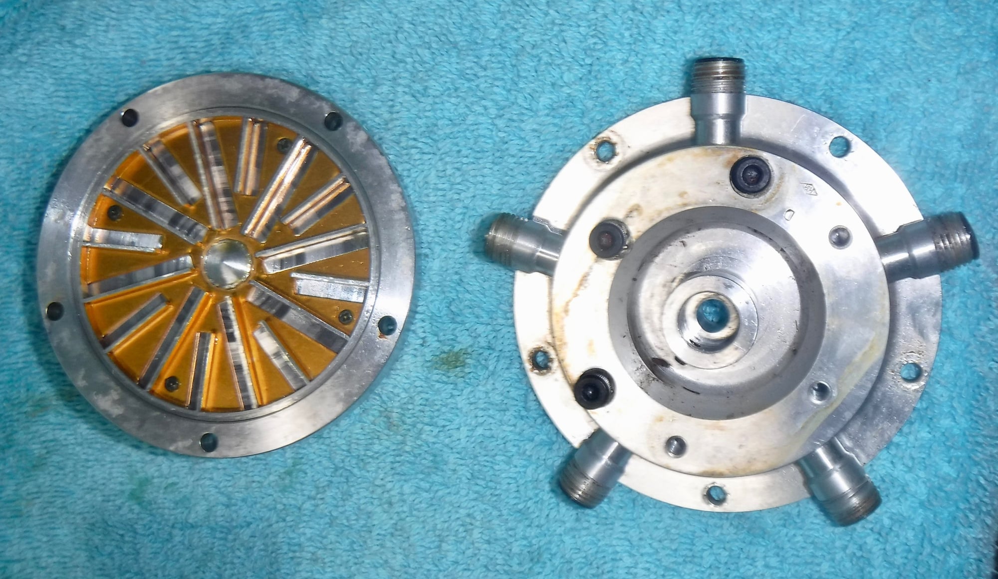
Take a look at this unit - Do you suppose the carb arrangement is to promote cam lubrication or something more? Could distrubute the intake charge to each side if the cam unit was a hollow shaft.
 03-29-2023, 07:29 AM
#1618
Senior Member
Thread Starter
I tend to agree with this idle analogy Bert... When flying nitro I always end up with an idle you have to baby a bit on the ground - makes for a nice low approach idle if needed. I put it to the loading of static vs Being "driven " by airflow but maybe its not that simple.. An off idle stumble on the ground often disappears in the air.. I do love the sound of a sub normal idle on the ground but would trade that anyway for a clean power band from 1/3 to WOT...
But it depends on how the engine was intended to be mounted, since twins usually have an "up" and a "down"...
04-01-2023, 06:40 AM
#1619
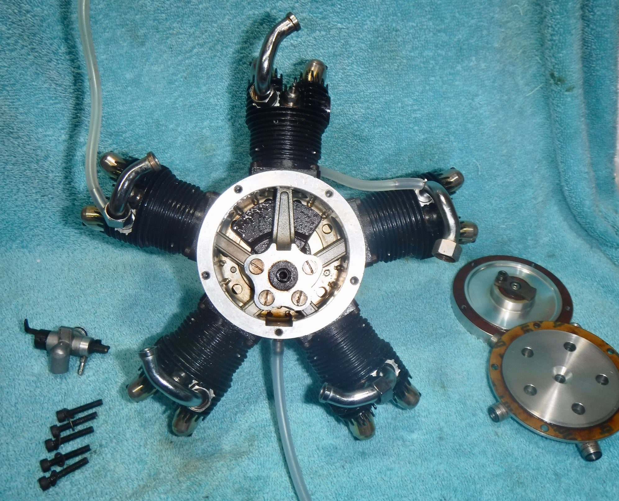
Interesting how Saito handled fuel distribution on the FA-325R5. The "impeller" on the left is supported by bearings and driven by the crankshaft. It mounts behind the intake manifold on the right.
 04-01-2023, 07:01 AM
#1622
Interesting that the holes out to the intake tubes appear like they are not at the outside periphery of the Rotor. You would think this would cause some Liquid fuel buildup in the area..
Is the master rod crank pin bushed or does it have a bearing?
Sorry for all the questions.. Never seen inside one of these...
Is the master rod crank pin bushed or does it have a bearing?
Sorry for all the questions.. Never seen inside one of these...
04-01-2023, 07:46 AM
#1624
Senior Member
Thread Starter
I seem to remember that OS also used some sort of crankdriven impeller/mixer device (from memory, so it is entirely possible that I confuse the Saito and the OS radials).
04-07-2023, 07:48 AM
#1625
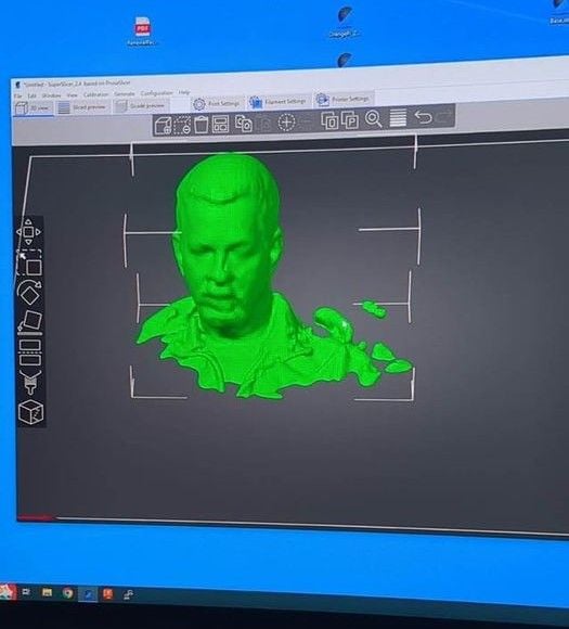
a bit off topic but i was playing with a 3d scanner and am about to make a pilot figure of myself. here's my first attempt using the scanner with the model in the slicer. you should do this, chris....
The following users liked this post:
BarracudaHockey (04-07-2023)