


Speeder Power.


 03-08-2023, 08:29 PM
#28
Banned
Thread Starter
While conventional winding processes have a copper filling factor of around 45 percent, it is just under 70 percent in this case. This increases power output and torque for the same volume. Another important advantage for a high-performance car like the Taycan is that a hairpin stator can be cooled considerably more efficiently.
The liquid-cooled synchronous motor on the front axle has an active length of 160 millimetres and an active diameter of 190 millimetres. Its counterpart on the rear axle is 210 millimetres long and has a diameter of 245 millimetres. All in all, the modules have the highest power density (kW per litre of package space) of all the electric powertrains on the market today.
The pulse‑controlled inverter is the most important component for controlling the electric motors. In the Taycan Turbo and Turbo S, a pulse-controlled inverter is mounted on each drive module on the front and rear axles. The pulse-controlled inverters convert the direct current supplied by the Performance Battery Plus into the alternating current required to drive the electric motors. The reverse happens during braking: Here they convert the alternating current obtained during recuperation into direct current for charging the battery. In the Taycan Turbo S, a pulse-controlled inverter with a maximum current of 600 amps is used on the front axle, which can generate even more power and torque than the 300-amp, pulse-controlled inverter of the Taycan Turbo. Both pulse-controlled inverters operate with a remarkably high efficiency of almost 98 per cent.
The knockers do not have any of this.
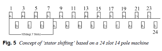
Design Guideline of an AC Hairpin Winding
- G. Berardi, N. Bianchi
- Published 1 September 2018
- Physics
- 2018 XIII International Conference on Electrical Machines (ICEM)

 03-09-2023, 09:36 AM
#33
Banned
Thread Starter
Ill be back on Flying giants at the end of this month. Nothing about the munch changes how the hairpins work. I wont erase anything I posted there.
This is his Doctorate contribution into the electric motor forum there; I have not found a single author reference to him in the IEEE. I have never heard of such a PhD.
Recent Attachments for rooman - FlyingGiants
Here are mine
Thread Gallery - FlyingGiants
Regards,
Hubert
This is his Doctorate contribution into the electric motor forum there; I have not found a single author reference to him in the IEEE. I have never heard of such a PhD.
Recent Attachments for rooman - FlyingGiants
Here are mine
Thread Gallery - FlyingGiants
Regards,
Hubert
Last edited by Clugh; 03-09-2023 at 09:39 AM.

 03-10-2023, 11:30 AM
#37
Banned
Thread Starter
Explanatory Note: The text below contains some recommendations on how to develop a modern motor controller. It contains some recommendations to help the designer to get the job done relatively quickly without an infinite struggle with doubts and discussions at every possible aspect of the project. The text does not pretend to be academically rigorous, rather it is more about practical ways of solving particular problems. Quoting Captain Barbossa: “This is more a set of guidelines than actual rules.”
Many of us come to this idea at one moment of our lives – to the idea of developing a custom brushless motor controller. It may arise for different reasons: you’re building a high-end vehicle with very specific requirements or you just need a decent controller. There is a certain set of steps that are to be taken to achieve this goal, all of which involve knowledge from different fields. It may be difficult for a single person to be competent in all these fields so this text describes an easier way of completing this challenge successfully. It reduces the skills and competencies needed and also drastically reduces the development time.
Let’s list all the stages of custom ESC development (supposing that high-level requirements like power level, input voltage range etc. have already been put in place):
A few of words about reliability should be made. In many cases, a controller is intended to control a motor mounted on some kind of aerial vehicle. This imposes special reliability requirements because a controller failure may lead to catastrophic consequences, not least the aircraft will be most probably critically damaged. This means that the software must be very reliable which can only be achieved by following standards like MISRA and doing lots of testing.
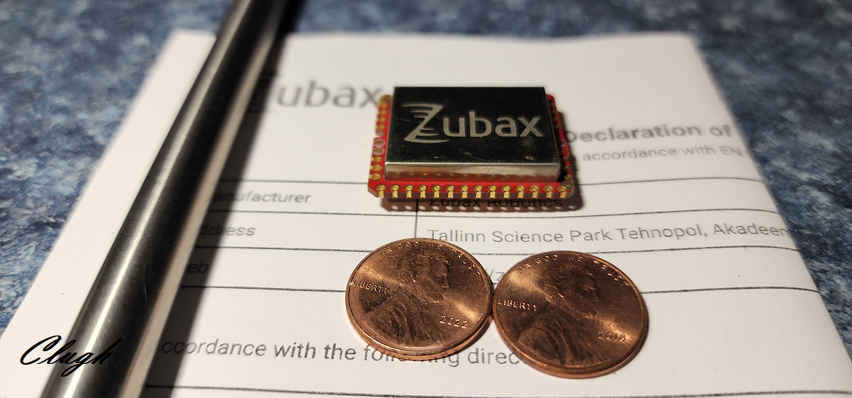
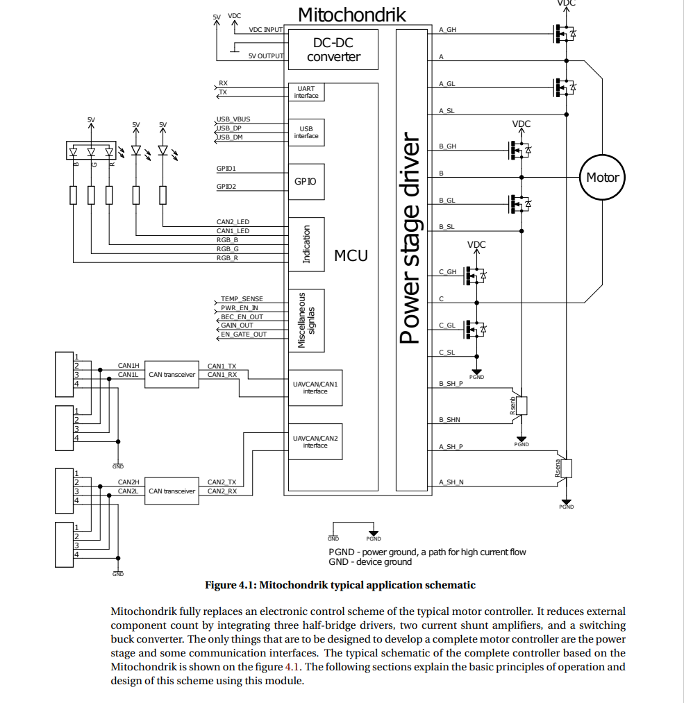
Conspicuously, the development of a motor controller from scratch is a major effort and one in which results are not guaranteed. But there is a way to avoid most of the challenges involved: use an integrated module for PMSM/BLDC motor control to do all the heavy lifting. This is what Zubax Mitochondrik LV 29 does. Of course, even with this help, the whole development process will be hardly a piece of cake but it does simplify it a lot. The main advantages are:
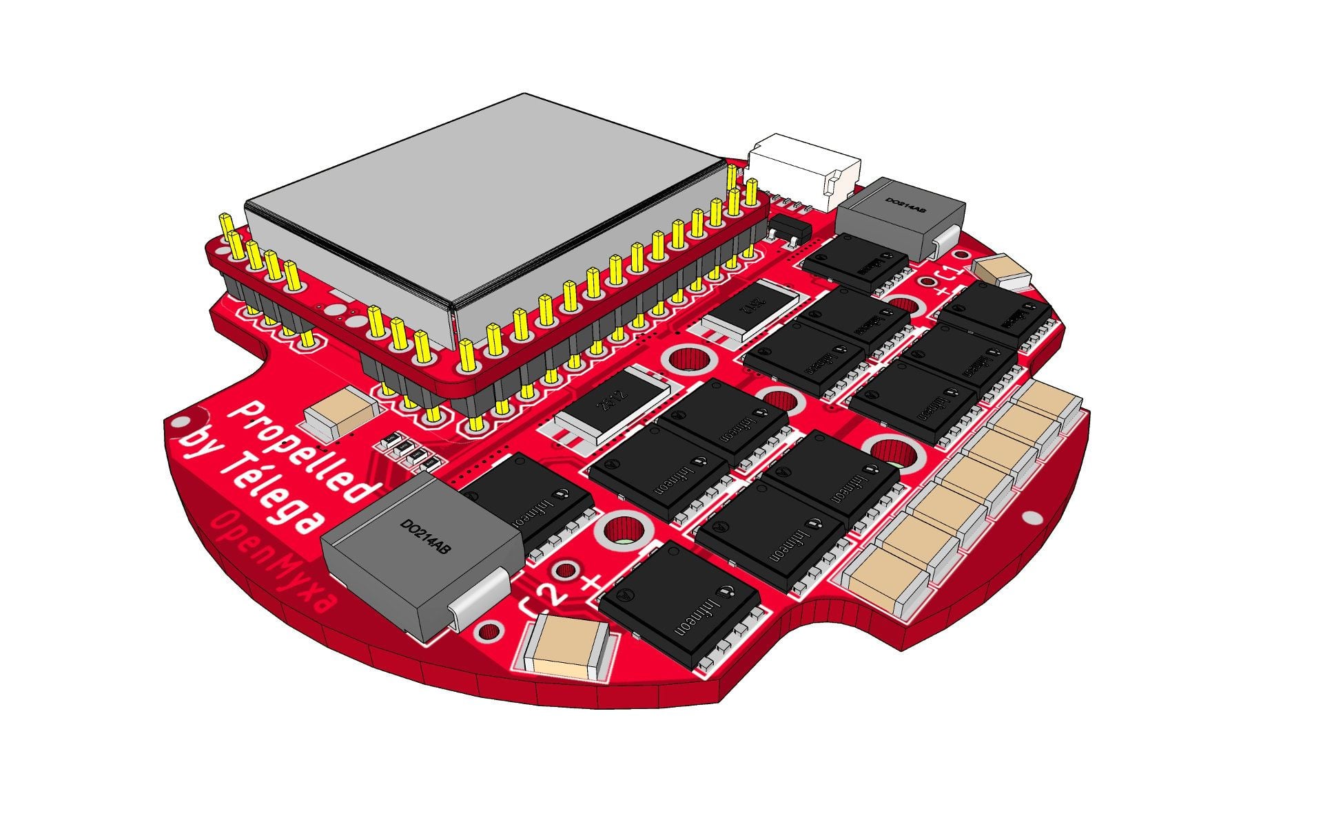
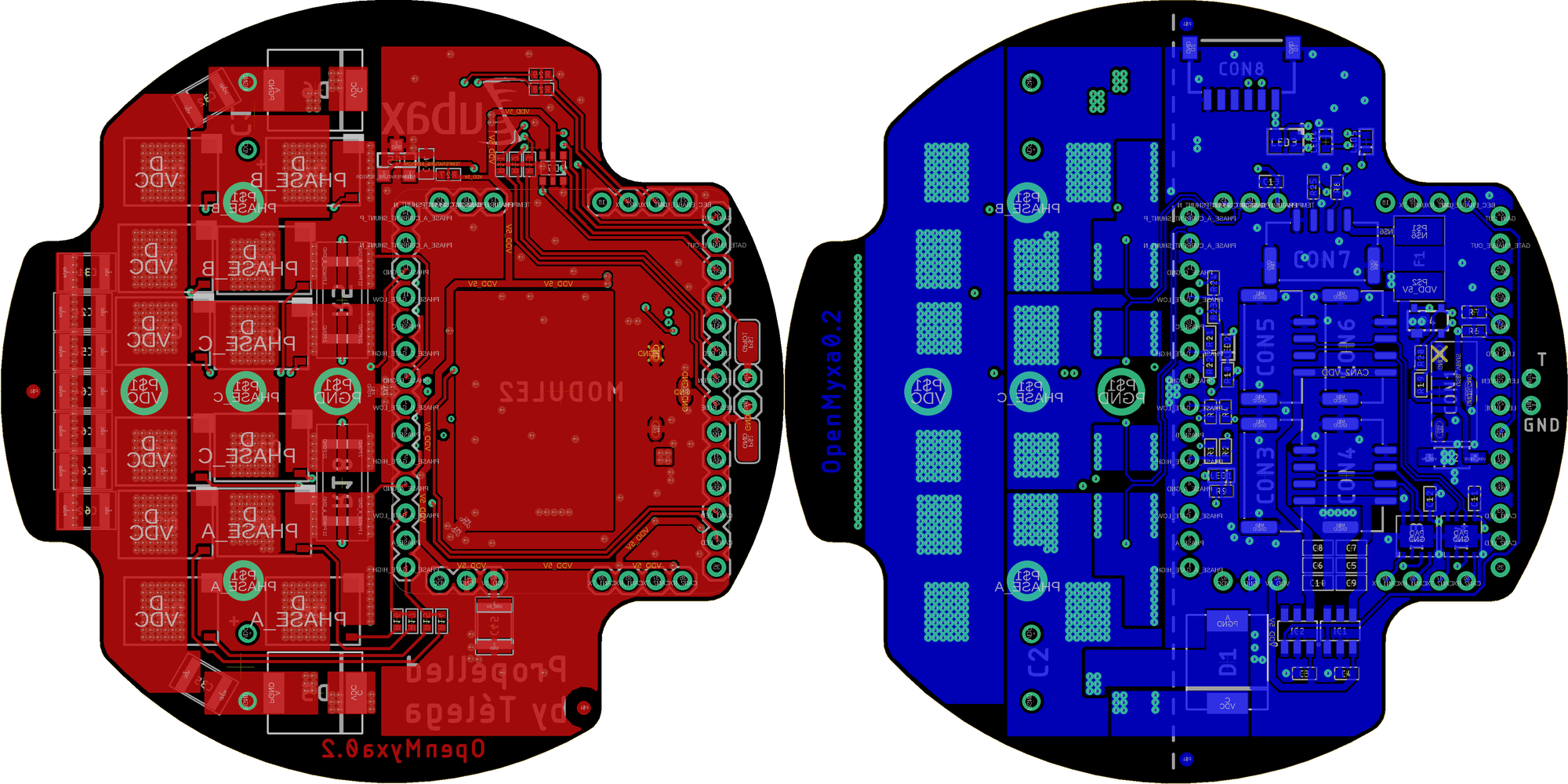
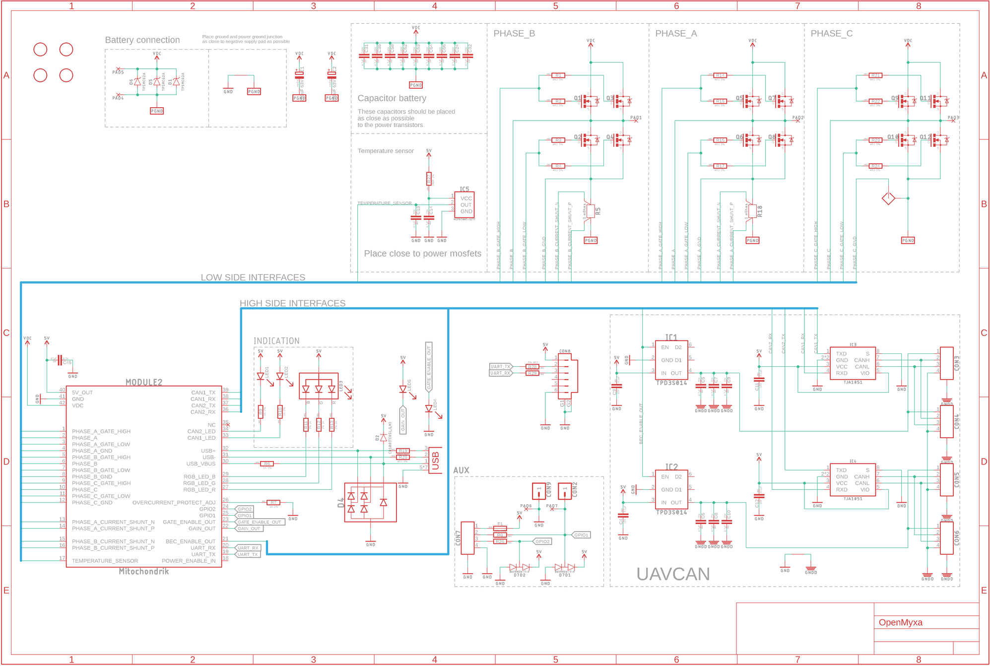
Below is an example of controller development using Mitochondrik LV using a Zubax Komar controller.
The initial requirements of the controller are:
Many of us come to this idea at one moment of our lives – to the idea of developing a custom brushless motor controller. It may arise for different reasons: you’re building a high-end vehicle with very specific requirements or you just need a decent controller. There is a certain set of steps that are to be taken to achieve this goal, all of which involve knowledge from different fields. It may be difficult for a single person to be competent in all these fields so this text describes an easier way of completing this challenge successfully. It reduces the skills and competencies needed and also drastically reduces the development time.
Let’s list all the stages of custom ESC development (supposing that high-level requirements like power level, input voltage range etc. have already been put in place):
- Pick up the main components: power MOSFETs, MOSFET driver, MCU, DC-DC converters, communication interface drivers and connectors etc.
- Carefully read all the datasheets to look for possible conflicts. (Just for reference, the datasheet for a modern MOSFET driver IC like DRV8350 from TI is a 100 pages long complex technical document).
- Create a schematic of the whole controller.
- Carefully think over the component arrangements taking into account things like possible electromagnetic issues, cooling and housing means, the ease of reach of the connectors, etc.
- Route the PCB; possibly, several times due to the errors made in the previous stages.
- Design a housing that is possible to manufacture using a selected technology (be it 3D printing or milling or whatever else).
- Software development and debugging.
- A GUI will be most probably needed to configure the controller.
A few of words about reliability should be made. In many cases, a controller is intended to control a motor mounted on some kind of aerial vehicle. This imposes special reliability requirements because a controller failure may lead to catastrophic consequences, not least the aircraft will be most probably critically damaged. This means that the software must be very reliable which can only be achieved by following standards like MISRA and doing lots of testing.
Conspicuously, the development of a motor controller from scratch is a major effort and one in which results are not guaranteed. But there is a way to avoid most of the challenges involved: use an integrated module for PMSM/BLDC motor control to do all the heavy lifting. This is what Zubax Mitochondrik LV 29 does. Of course, even with this help, the whole development process will be hardly a piece of cake but it does simplify it a lot. The main advantages are:
- The only components that have to be selected are the power stage components, interface ICs and connectors. Generally, the hardest part is selecting the power MOSFETs, proper capacitors and shunt resistors for the current measurements.
- The schematic and PCB design are greatly simplified as all the complex circuitry is embedded into the module.
- There is no need to mess with the DC-DC converter design as it is embedded into the module.
- And most importantly; no programming needed. Mitochondrik LV runs T�lega software 10 which uses advanced and sophisticated algorithms to control the motor. Also, there is a standard GUI tool for T�lega-based controllers already so no additional PC-software development is needed either.
Below is an example of controller development using Mitochondrik LV using a Zubax Komar controller.
The initial requirements of the controller are:
- Input voltage range: 20 – 50.4 V.
- Continuous power output: 2 – 2.8 kW with a 12S battery where the range of possible battery voltages is 40 – 50.2 V.
- Dimensional requirements: Circular and comparable in size to a compact 2 kW-rated motor like the T-motor MN5212.
03-10-2023, 11:32 AM
#38
Banned
Thread Starter
T�lega
State-of-the-art PMSM/BLDC motor control solution for aerospace applications and robotics.T�lega is an advanced electric motor control solution (PMSM/BLDC) for aerospace and robotic applications. Telega implements new approaches to digital signal processing that enable high energy efficiency and excellent dynamic characteristics. Telega supports a wide variety of communication interfaces and auxiliary features that enable easy integration into the end application.
Performance
T�lega employs new approaches to digital signal processing (DSP), which in combination with a proprietary field-oriented control (FOC) algorithm enable a significant improvement in energy efficiency, better dynamic characteristics and higher robustness compared to traditional PMSM/BLDC drives, including modern vector control solutions from other vendors.Higher energy efficiency and the resulting decrease in heat dissipation allows T�lega-based drives to achieve higher power output in smaller form factors.
Built-in robust motor identification routines ensure compatibility with many PMSM or BLDC motors with minimal manual tuning required. Further performance optimization for a particular motor is possible with manual tuning, which is an optional service provided by Zubax Robotics (please email [email protected] for details).
Versatility
Supported communication interfaces:- CAN bus with optional dual bus redundancy for safety-critical applications.
- RC PWM for UAV/robotic applications.
- Support for analog motor temperature sensors.
Applications
- Propeller and fan drives in electric aircraft (manned/unmanned).
- Pump and propeller drives in electric watercraft.
- Fuel pumps for jet engines and gas turbines.
- Propulsion systems in ground robots and EVs.
Reliability
Robust sensorless operation even with poorly characterized (low cost) motors.The hardware implementations are made to withstand harsh environments and employ AEC-Q qualified components (consult with the specific product documentation for the list of exceptions).
Every manufactured unit undergoes a rigorous automatic testing procedure at the factory. The test reports are available online for every delivered device. Extended traceability data is available upon request.
Testimonials
“I want to express my gratitude to you for such a successful controller, it really allowed to increase the flight duration of one of our production vehicles by 25%.”
- Lipovy Andrey (Chief Designer at Spaitech LLC)
“Today I had a chance for a first "serious” test. It was done with 6S, so maximum thrust was “only” 5 kg. But it may be interesting for you, that we could achieve 3.1 kg thrust with only about 200W - which means 16 g/W efficiency. A pretty good value at 3.1 kg. It looks like your ESC is already a winner for us!
.“
- Helge Hackbarth (Managing Director at KopterKraft O�)
"We took a known problematic motor that would always get bogged down in rapid acceleration and skip and [Myxa] made it work. Quality is top notch […], no corners cut on that.”
- Ryan Johnston (CEO at Applied Aeronautics)
- Lipovy Andrey (Chief Designer at Spaitech LLC)
“Today I had a chance for a first "serious” test. It was done with 6S, so maximum thrust was “only” 5 kg. But it may be interesting for you, that we could achieve 3.1 kg thrust with only about 200W - which means 16 g/W efficiency. A pretty good value at 3.1 kg. It looks like your ESC is already a winner for us!
- Helge Hackbarth (Managing Director at KopterKraft O�)
"We took a known problematic motor that would always get bogged down in rapid acceleration and skip and [Myxa] made it work. Quality is top notch […], no corners cut on that.”
- Ryan Johnston (CEO at Applied Aeronautics)
Last edited by Clugh; 03-10-2023 at 11:40 AM.
03-10-2023, 03:14 PM
#40
Banned
Thread Starter
Motor control fundamentals - Telega v1.0 Reference Manual (zubax.com)
And so we see a hobbyist CAN create an inverter more sophisticated than YGE's 320. Talega is not like most vector control FOC strategies as only commutates in a 2 thirds state like a BLDC which runs cooler and more efficiently.. Being able to run the propeller and record the torque coefficients and then put that back into the control loop is really a way to ward higher efficiency with any given propellor. Ivce looked at the spec and already selected a few different 80V 8 pin FETS that should work in the bridge topology with the MitochodrikLV as well as current shunts so its time to thinking about some bridge designs for a start of the arr open source DIY inverter.
Regards,
Hubert
Last edited by Clugh; 03-10-2023 at 08:43 PM.
 03-10-2023, 11:51 PM
#42
Banned
Thread Starter
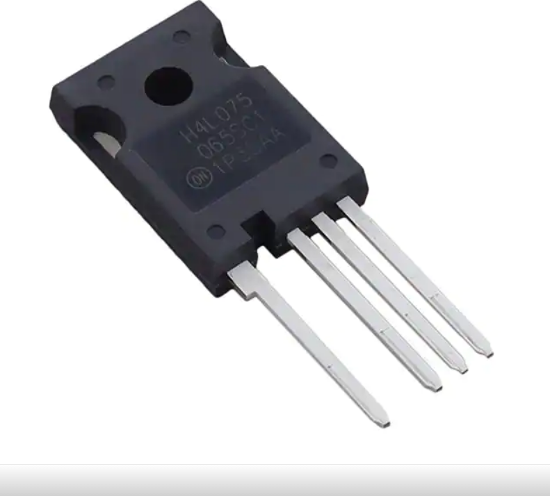
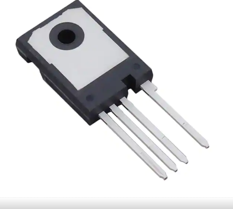
And so you can see why the YGE 320 would be limited. The old packaged 3 pin fets it uses have a high gate chage. Im comparison to new fets they are slow. so the gate charge value is high. The problem here is the gate current required at the pwm frequencies . Is for typical sinus inverter you have to account for the gate charge of 100% of fets at the pwm frequency. With a high gate charge per fet depending on the current capably of the fet driver bootstrap topology if the charge current of of the fet gates exceeds what the driver commands it wont have the switched speed to maintain the pwm. You cannot put many of those large slow fets in parallel and switch them at a pwm. Even though it is a fet that can sink large current individually you can run many in parallel for and ultra low on resistance and switch them at high pwm. The Telega based inverter can switch at a 48Kkz pwm and unlike most sinus drives it only switches 2/3rds of the transistors on at any moment of commutation so it more efficient. To do this it uses more modern faster switching transistors with much lower gate charge so you can run alot more in parallel and maintain adequate switching charge speed at much higher PWM. The gate charge iof the YGE fett is probably 2 to 3 times higher than The MYXA.
Regards
Hubert
Regards
Hubert
Last edited by Clugh; 03-11-2023 at 12:07 AM.
03-11-2023, 05:41 AM
#45
Banned
Thread Starter
Powercroco and Audiosmith know nothing really about electronics so they say crazy things on Rc-network.de.like no hobbyist can build an inverter as good as YGE.
Hmm Im a hobbyist and I can......
Regards
Hubert
Hmm Im a hobbyist and I can......
Regards
Hubert
03-11-2023, 05:51 AM
#46
Banned
Thread Starter
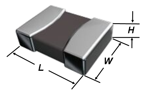
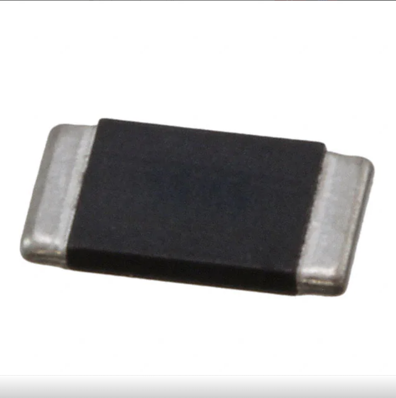
The Telega based inverter for a beginning has a faster more intelligent brain than a YGE 320. . It also has the special vector control algorithm that only switches on the necessary fets to do the job which allow it to run at least a 1/3rd cooler than YGE . The FET I have are advanced in comparison with a Tson 1.27mm pitch 8 pin copper pad selected is also a dual side cool fet and it is also optimized for synchronous rectification. The speed bubble goof troop doesn't know anything about inverter design.. And now with my design it will have even a betetr fet that the original inverter concept. You have to find one that works in its safe operating zone for the application has lor on resistance and a small gate charge.
Verbesserung der digitalen Kommutierung an sensorlosen Brushlessmotoren | Seite 2 | RC-Network.de
The "boys" on rc-neteork.de need a manual! on inverter design and multilayer hairpin windings and Powercroco nor some forum idiot from Pa can provide it!

When using bottom-side cooling solutions (e.g. SuperSO8, PQFN 5x6) most of the heat generated by the MOSFETs are transferred to the PCB, increasing the PCB temperature due to its poor thermal resistance. Dual-side cooling solutions add another thermal path (bottom through PCB + top through exposed clip and heatsink) to dissipate the heat generated in the MOSFET die.
About 30 percent of the heat generated on the MOSFET die is transferred through the top and less heat is transferred to the PCB. Thus,
Verbesserung der digitalen Kommutierung an sensorlosen Brushlessmotoren | Seite 2 | RC-Network.de
The "boys" on rc-neteork.de need a manual! on inverter design and multilayer hairpin windings and Powercroco nor some forum idiot from Pa can provide it!
OptiMOS™ power MOSFETs 40 V - 150 V in SuperSO8 DSC package with dual-side cooling for enhanced thermal performance
OptiMOS™ 6 40 V and OptiMOS™ 5 40 V-150 V power MOSFETs in SuperSO8 DSC (dual-side cooling) package offer all thermal management benefits of dual-side cooling solutions with industry-standard footprint.When using bottom-side cooling solutions (e.g. SuperSO8, PQFN 5x6) most of the heat generated by the MOSFETs are transferred to the PCB, increasing the PCB temperature due to its poor thermal resistance. Dual-side cooling solutions add another thermal path (bottom through PCB + top through exposed clip and heatsink) to dissipate the heat generated in the MOSFET die.
About 30 percent of the heat generated on the MOSFET die is transferred through the top and less heat is transferred to the PCB. Thus,
- either the PCB runs cooler at the same power dissipation for improved reliability,
- or more power can be handled by the MOSFET for higher power density
Last edited by Clugh; 03-11-2023 at 06:15 AM.
03-11-2023, 06:10 AM
#47
Banned
Thread Starter
You see they are their with old notes on FOC and do not have the ability to engineer the logic and driver side if they can firstt build a bridge. It all just falls to the bottom when the keyboard is no longer stroked . Heere you will be provided with a BOM to get started.
Talk is cheap.
Regards
Hubert
Talk is cheap.
Regards
Hubert
Last edited by Clugh; 03-11-2023 at 06:17 AM.
03-11-2023, 06:21 AM
#48
Banned
Thread Starter
How is it the Boys are speaking "in depth " about inverter design and do not know even how to select the right components based on the MCU and driver specification sheets and their application? How does that style of inverter design work?
BEWARE!
Regards
Hubert
03-11-2023, 06:41 AM
#49
Banned
Thread Starter
The original Talega Koma @ the expected 65 amps phase current uses a Bourns 2 megaohm current shunt. What will their inverter use? The hardware editors have it covered I'm sure. Or at least I have given them enuf here to calculate it.. You also have to know if the MCU is going to be switching the fets in their safe zones of operation. Everything has to be specified for your application.
Last edited by Clugh; 03-11-2023 at 07:09 AM.
03-11-2023, 07:09 AM
#50
Banned
Thread Starter
I also see I have revitalized the Germ�n discussion about it which had been dead for several weeks!
I hope Ralps goof troop can accept based on its onboard hardware in plain view to the engineers eye that....
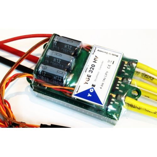
The YGE 320's processor, driver speeds @ 16khz maximum PWM, driving periphery inverter bridge hardware sporting D2PAK Mosfets is clearly very antiquated in 2023???
Peel the sticker off pimp!
Because a real engineer can look at the hardware and spec it at first glance.
Old school just like Powercrocos winds.
Regards
Hubert
I hope Ralps goof troop can accept based on its onboard hardware in plain view to the engineers eye that....
The YGE 320's processor, driver speeds @ 16khz maximum PWM, driving periphery inverter bridge hardware sporting D2PAK Mosfets is clearly very antiquated in 2023???
Peel the sticker off pimp!
Because a real engineer can look at the hardware and spec it at first glance.
Old school just like Powercrocos winds.
Regards
Hubert
Last edited by Clugh; 03-11-2023 at 07:18 AM.