


OS 50cc Gemini Twin Gasoline Conversion
 03-01-2023, 05:26 AM
#76


Mitch,
Looking good. A very tidy package, will make for a slick, professional installation.
Venting oil to the stack works very well here. At some point you may want to try a longer stack.Lonnie's note on the magnet gap is a good one. Neodymium magnets die a continual slow death when used at elevated temperatures. The
Is that a CDI to CDI comparison?
I see 18% > 20% between gasoline and straight methanol. CDI on both.
The improved timing control also allows for safely increasing the compression ratio in methanol fueled,CDI over the glow fired version.
Looking good. A very tidy package, will make for a slick, professional installation.
Venting oil to the stack works very well here. At some point you may want to try a longer stack.Lonnie's note on the magnet gap is a good one. Neodymium magnets die a continual slow death when used at elevated temperatures. The
I've been seeing closer to an 18% reduction in HP moving from 15% nitro to gas on my conversions.
........
Adrian at CH is getting 7000 with a Xoar 21x8.
https://youtu.be/wgTW9qUTQRs
........
Adrian at CH is getting 7000 with a Xoar 21x8.
https://youtu.be/wgTW9qUTQRs
I see 18% > 20% between gasoline and straight methanol. CDI on both.
The improved timing control also allows for safely increasing the compression ratio in methanol fueled,CDI over the glow fired version.
Last edited by Jesse Open; 03-01-2023 at 05:30 AM.
 03-01-2023, 03:14 PM
#77
Mitch,
Looking good. A very tidy package, will make for a slick, professional installation.
Venting oil to the stack works very well here. At some point you may want to try a longer stack.Lonnie's note on the magnet gap is a good one. Neodymium magnets die a continual slow death when used at elevated temperatures. The
Is that a CDI to CDI comparison?
I see 18% > 20% between gasoline and straight methanol. CDI on both.
The improved timing control also allows for safely increasing the compression ratio in methanol fueled,CDI over the glow fired version.
Looking good. A very tidy package, will make for a slick, professional installation.
Venting oil to the stack works very well here. At some point you may want to try a longer stack.Lonnie's note on the magnet gap is a good one. Neodymium magnets die a continual slow death when used at elevated temperatures. The
Is that a CDI to CDI comparison?
I see 18% > 20% between gasoline and straight methanol. CDI on both.
The improved timing control also allows for safely increasing the compression ratio in methanol fueled,CDI over the glow fired version.
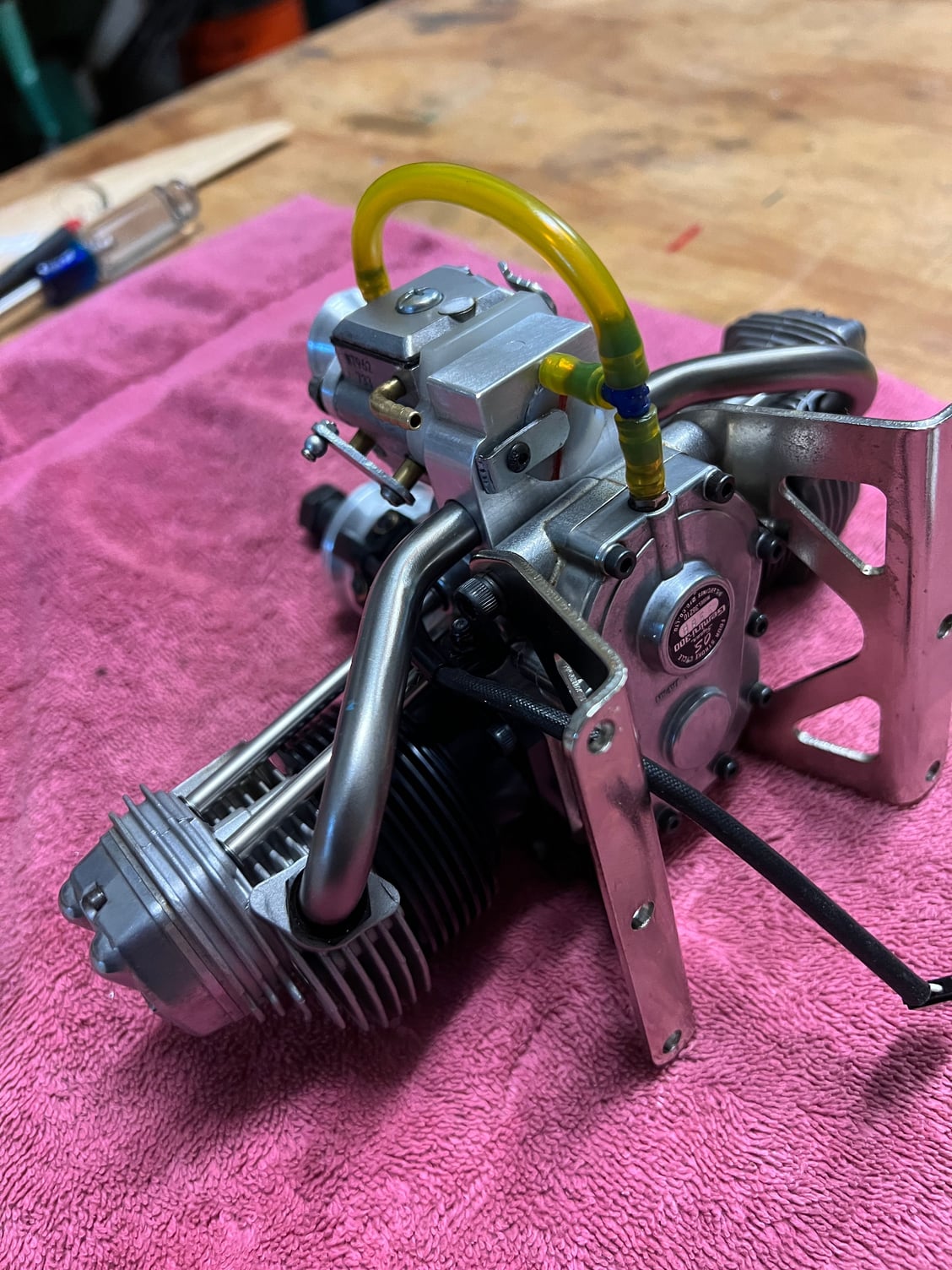
I got it on the stand and ran it this evening. Took a while to get that virgin carb filled with fuel but once I did she fired right up and ran with the needles close to where they were out of the package. The running characteristics are naturally very reminiscent of its little 25cc brother - in other words it runs great. But I will say this: it got good and hot in the few minutes I ran it. I would not want to run it indefinitely on the stand without some forced air cooling. And that with a small-ish prop (20x8).
Tomorrow I will take it out to my flying field and video it for all of you that have been following this thread.
 03-01-2023, 04:31 PM
#78
Some things that cause gassers to run hotter than normal:
Too lean fuel mixture
Too rich fuel mixture (excessive afterburning in exhaust tract)
Ignition timing retarded too far (late burn too far down the cylinder wall)
Looking toward to the run vid, hopefully with a tach and prop size mentioned.
Too lean fuel mixture
Too rich fuel mixture (excessive afterburning in exhaust tract)
Ignition timing retarded too far (late burn too far down the cylinder wall)
Looking toward to the run vid, hopefully with a tach and prop size mentioned.
03-02-2023, 05:18 AM
#79
03-02-2023, 06:53 AM
#80
The 20% figure is a good overall rating between methanol (no nitromethane) and gasoline.
The methanol / CDI can take good advantage of boosted compression ratio as well. (Over the same methanol fueled engine on glow plug ignition)
The methanol / CDI can take good advantage of boosted compression ratio as well. (Over the same methanol fueled engine on glow plug ignition)
Last edited by Jesse Open; 03-02-2023 at 07:07 AM.
03-02-2023, 01:36 PM
#81
I love it when a thread I start generates such interesting conversation between all you smart guys out there!
Well, you asked for it so here it is - the run video. You will notice that I attached thermocouples to each exhaust pipe to simulate exhaust gas temp. There’s a LOT to unpack in these little snippets and I look forward to some good conversation. In case it’s not obvious, the last snippet is the condition of the oil recirculating back into the inlet.
Well, you asked for it so here it is - the run video. You will notice that I attached thermocouples to each exhaust pipe to simulate exhaust gas temp. There’s a LOT to unpack in these little snippets and I look forward to some good conversation. In case it’s not obvious, the last snippet is the condition of the oil recirculating back into the inlet.
Last edited by mitchilito; 03-02-2023 at 02:12 PM.
03-03-2023, 04:25 AM
#82
That for the vid, Mitch. Funny when the tach flew from your hand. 
Seems to run good but a bit down on power if using a Xoar 20x8. Obviously richer on the left cylinder. Does the compression between cylinders feel close to the same?
The location of your thermocouples, although attached to the exhaust tube, are measuring closer to what one would expect cylinder head temps to be but are being greatly affected by the lack of enthalpy in the thin exhaust tubes. With the TC's mounted there temps are going to rise and fall dramatically and quickly making it difficult to get a consistant reading. A better placement would be between two cylinder cooling fins, against the cylinder wall and near the exhaust port. That's an area that better represents CHT and will give more consistent readings. Many use JBweld or some similar product to attach the TC's. Positioning the TC in precisely the same spot on each cylinder is helpful for cylinder load comparisons. Either way, measuring CHT accurately is not what's important for our purposes, repeatability is.
Here's a link that may interest you: https://resources.savvyaviation.com/...0low%20stress.
03-04-2023, 04:20 AM
#83
That for the vid, Mitch. Funny when the tach flew from your hand.
Seems to run good but a bit down on power if using a Xoar 20x8. Obviously richer on the left cylinder. Does the compression between cylinders feel close to the same?
The location of your thermocouples, although attached to the exhaust tube, are measuring closer to what one would expect cylinder head temps to be but are being greatly affected by the lack of enthalpy in the thin exhaust tubes. With the TC's mounted there temps are going to rise and fall dramatically and quickly making it difficult to get a consistant reading. A better placement would be between two cylinder cooling fins, against the cylinder wall and near the exhaust port. That's an area that better represents CHT and will give more consistent readings. Many use JBweld or some similar product to attach the TC's. Positioning the TC in precisely the same spot on each cylinder is helpful for cylinder load comparisons. Either way, measuring CHT accurately is not what's important for our purposes, repeatability is.
Here's a link that may interest you: https://resources.savvyaviation.com/...0low%20stress.
I was a little disappointed that I wasn't seeing 7K rpm - especially with that small-ish prop. The compressions feel fantastic but the right cylinder does feel a tiny bit better. It sure doesn't feel like a compression problem. I put the ignition timing setup on it again last night just to make sure and it was dead on 30 degrees BTC. Right where I want it.
I'm wondering how much difference in performance the hot crankcase discharge air/oil mix going into the intake might make. Probably not a lot but I'll try disconnecting it and see. Over all it's making acceptable power and not really running too hot so I might be happy with it as is. I can tell this engine has had considerable time on it in the past although it seems in great shape so I'll keep looking for the missing performance.
And last but not least I was happy to see the front of the engine was running under 100 degrees F which bodes well for magnet life.
Last edited by mitchilito; 03-04-2023 at 04:31 AM.
03-04-2023, 05:00 AM
#84
All good, Mitch. If it makes adequate power to fly the bird to your liking you've already won.
Sure, the extra oil content in your mix and the fact you're recycling all of it will rob top end power. Adrian at CH and MMM run 20:1, I believe with no recirc.
It can take a very long time to seat/reseat OS and Saito rings. Sometimes it seems like forever, gallons of fuel sometimes, to see compression equalize on multi cylinder engines. I've gotten into to habit of swapping them out for RMJ/Bowman rings to speed up the process. No more than a 1-1/2 quarts of fuel and the compression is rock hard with little leakdown. A worthwhile investment IMO. Until that happens, solid compression on all cylinders, you're just chasing your tail attempting to equalize fuel mixtures.
I'm quite familiar with Bert's mods, both for equalizing fuel mixtures on multi cylinder engines and his gas conversion strategy. I'm running his microcontroller/solenoid system on two Saito FA-180's and an FA- 220. It's a very slick system and easy enough to implement for those of us with no machining tools or those that are machining challenged.
In all honesty, I would rather mod them as you have, for cube carbs. Much more challenging, fun and rewarding that way. Speaking of which, you have done a bang up job on your gas conversions.
Last edited by Glowgeek; 03-04-2023 at 05:31 AM.
03-04-2023, 10:55 AM
#85

Join Date: Jan 2004
Location: lake in the Hills,
IL
Posts: 977
Likes: 0
Received 14 Likes
on
14 Posts
I know I'm slow at providing good info, but, here are some thoughts.
The high quality 50cc DA single I have likes a 22 x 8 @ ~ 7000 rpm. I ran an early 40cc SPE for years with a 20 x 8 @~ 7300 rpm. I ran a ST 3250 on a 18 x 6 @ ~ 10500 rpm with glow 0% nitro.
Point: A twin 4 cycle conversion will not match the same as a single 2 cycle of equal displacement.
Conclusion: Be happy, Don't worry. I think you are close to where you should be.
Yes try different props, carbs, even plug gaps, maybe little timing changes and fuel oil ratios.
In the end, put that bad boy in the air and enjoy!
03-04-2023, 12:25 PM
#86
I know I'm slow at providing good info, but, here are some thoughts.
The high quality 50cc DA single I have likes a 22 x 8 @ ~ 7000 rpm. I ran an early 40cc SPE for years with a 20 x 8 @~ 7300 rpm. I ran a ST 3250 on a 18 x 6 @ ~ 10500 rpm with glow 0% nitro.
Point: A twin 4 cycle conversion will not match the same as a single 2 cycle of equal displacement.
Conclusion: Be happy, Don't worry. I think you are close to where you should be.
Yes try different props, carbs, even plug gaps, maybe little timing changes and fuel oil ratios.
In the end, put that bad boy in the air and enjoy!
The high quality 50cc DA single I have likes a 22 x 8 @ ~ 7000 rpm. I ran an early 40cc SPE for years with a 20 x 8 @~ 7300 rpm. I ran a ST 3250 on a 18 x 6 @ ~ 10500 rpm with glow 0% nitro.
Point: A twin 4 cycle conversion will not match the same as a single 2 cycle of equal displacement.
Conclusion: Be happy, Don't worry. I think you are close to where you should be.
Yes try different props, carbs, even plug gaps, maybe little timing changes and fuel oil ratios.
In the end, put that bad boy in the air and enjoy!
I have a sneaking suspicion that this particular Xoar prop could very well be causing some of the missing RPM. There's really no telling and you are right K, I should be, and am, happy with it right now. I've mentioned elsewhere in this thread that I'm building a 50% Bucker Jungmiester so I'm jumping back on that. But some day in the not too distant future I WILL be designing a perfect plane for this engine. Like I mentioned, I'm shooting for a vintage looking biplane: very much like a bipe version of the Rascal but sized up to fit this engine. I already love my Gemini powered Rascal 110 with a burning passion so a big bipe that I designed/built and with this big Gemini would really be a dream come true for me.
I needed to make a decent choke lever to complete the project so here's some final eye-candy.
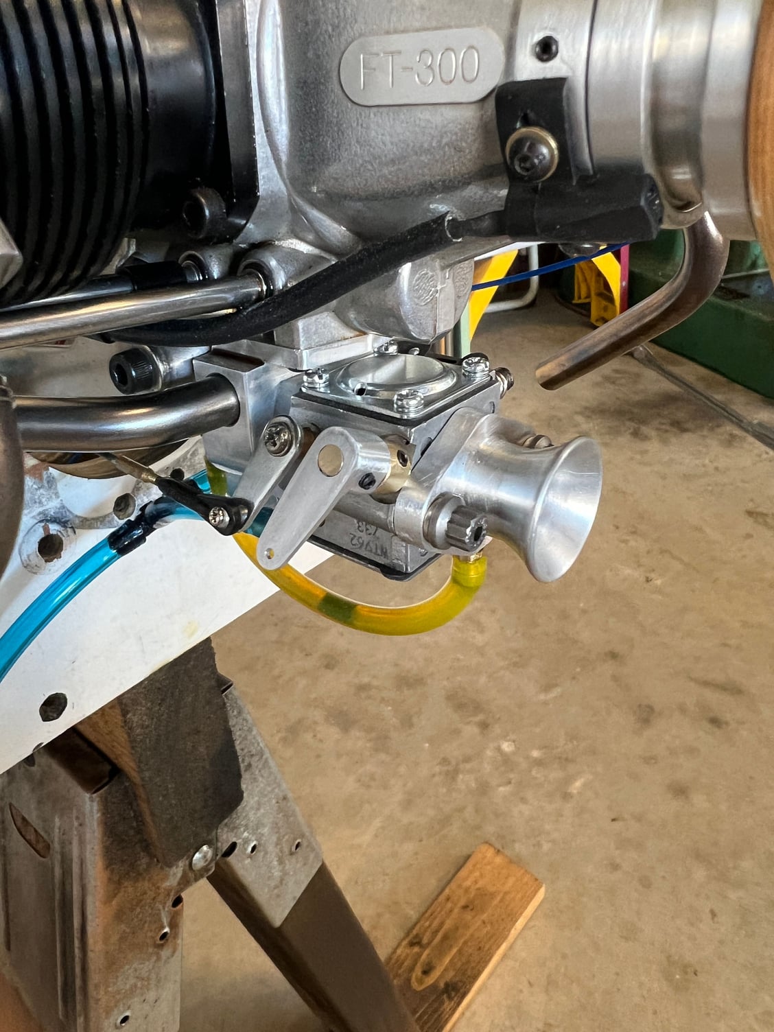
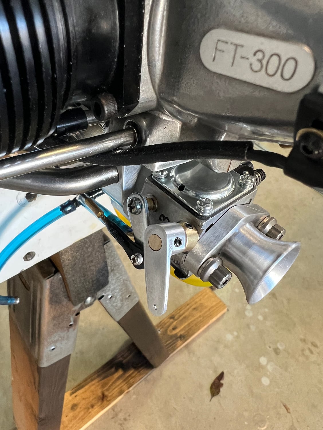
In this pic you see i downsized the hole in the choke plate. Needed more vacuum.
Last edited by mitchilito; 03-04-2023 at 12:31 PM.
The following users liked this post:
Jesse Open (03-04-2023)
03-04-2023, 04:13 PM
#87
Thanx for the pix Mitch.
Throttle arms are one of my favorite projects too.

Along with intake stacks and exhaust systems
Gives me a chance to get out the radius turning attachment and turn some real radii.
Throttle arms are one of my favorite projects too.
Along with intake stacks and exhaust systems
Gives me a chance to get out the radius turning attachment and turn some real radii.
Last edited by Jesse Open; 03-04-2023 at 04:16 PM.
The following users liked this post:
mitchilito (03-05-2023)
03-18-2023, 12:07 PM
#89
I found another nice Gemini 300. This one is in much better shape - pretty low time engine. I transferred everything over and ran it today and was surprised to see the exact same 6750 max rpm. I have a VERY strong feeling it's low on rpm because of the difference in mixtures between cylinders. I'm going to have to figure out how to balance them.
This latest engine is in MUCH better shape than my original - but runs exactly the same. Hmmmmm
This latest engine is in MUCH better shape than my original - but runs exactly the same. Hmmmmm
03-19-2023, 05:33 AM
#90
So the situation is this: just like on my little 25cc Gemini, the left cylinder runs much richer than the right. So I need to bias the fuel charge more towards that right cylinder. The good news is, I have plenty of room behind the manifold for bumps or bulges when I add some kind of diverter device. Take a look at the pictures and maybe you smart people out there can give me some suggestions?

Detail of the inside of the manifold. I'm thinking some kind of drum (the size of that hole) with biased vanes on it. Maybe it could rotate to adjust the bias.

Plenty room in back bumps/bulges, screws etc.
Ditto
Almost no limit to what I could mount to the back of that manifold right in line with the intake flow.
Detail of the inside of the manifold. I'm thinking some kind of drum (the size of that hole) with biased vanes on it. Maybe it could rotate to adjust the bias.
Plenty room in back bumps/bulges, screws etc.
Ditto
Almost no limit to what I could mount to the back of that manifold right in line with the intake flow.
03-19-2023, 06:04 AM
#91
Instead of a vane or other diverter, I would personally try first with a fine mesh metal screen: Vapour will pass, any liquid will spread over the wire surface and not only be given an extreme amount of evaporating surface, it would also spread evenly.
The amount of opening of the butterfly valve will affect the direction of airflow and the location of vortexes, So will the air velocity. Chances are, diverters or deflectors will have different affectiveness at different RPM/throttle opening.
A screen would be the same throughout the range. It also has the effect of smoothing out the airflow, possibly improving the cylinder filling at the same time because of a more laminar airflow.
None of my carbs are flange-mounted or I would have tested this theory myself, but yours is....
An experimental "quicky" could be made in minutes just to test it: Two not too thin gaskets with a suitable piece of metal gauze wedged inbetween should either show no change at all, or dramatic improvement.
Last edited by 1967brutus; 03-19-2023 at 06:07 AM.
03-19-2023, 08:04 AM
#92
My Feedback: (1)
That's a great idea Brutus has. Are both intake tubes the same length and have approximately the same restrictive bend? Rather than restrict the rich side is there a way to increase flow to the lean side? This group is incredibly sharp and I'm sure you'll figure it out. Nice work.
03-19-2023, 08:57 AM
#93
Join Date: Jan 2004
Location: lake in the Hills,
IL
Posts: 977
Likes: 0
Received 14 Likes
on
14 Posts
I see what I would call a left cylinder bias. I think the cause is the 22 degree angle alignment of the throttle plate and shaft to your intake manifold. Idle circuits are aligned with throttle plate, but, even though the high speed jet is centered. The path is very short for air and fuel to mix completely before the intake tubes maybe causing the left side to be richer.
I like 1967brutus's experiment, but, it may change the peak rpm due to decreased flow.
Could the carb be rotated 22 degrees so the throttle shaft was parallel to the intake?
Just a guess..
I like 1967brutus's experiment, but, it may change the peak rpm due to decreased flow.
Could the carb be rotated 22 degrees so the throttle shaft was parallel to the intake?
Just a guess..
Last edited by kmeyers; 03-19-2023 at 08:59 AM.
03-19-2023, 09:26 AM
#94
I'm wondering if that sharp 90� turn just inside the manifold my be causing an eddy effect, dropping fuel out of vapor suspension. Creating a radius (grinding) on that squared off edge to create a short turn radius may improve things. Grinding a radius inside the carb body to match the one ground in the manifold would create an even longer short turn radius. Every little bit helps.
Bert's mesh idea is a proven one for diffusing airflow in mass airflow sensors, may help in this situation as well.
Bert's mesh idea is a proven one for diffusing airflow in mass airflow sensors, may help in this situation as well.
Last edited by Glowgeek; 03-19-2023 at 09:29 AM.
03-19-2023, 10:06 AM
#95
Join Date: Jan 2004
Location: lake in the Hills,
IL
Posts: 977
Likes: 0
Received 14 Likes
on
14 Posts
If there is room, I had an engine where the insulating block had inserts for the carb mounting screws rotated to change the throttle and choke angle. The block had through holes for mounting the block.
Please stop me, I may be ideating for long time.
Please stop me, I may be ideating for long time.
03-19-2023, 01:19 PM
#96
Even if the venturi of the carb has the same diameter as the separate header tubes, that would STILL mean that the mesh would be at a location of lower velocity, and thus a mesh would not present a real resistance.
Not too worried about that.
03-19-2023, 01:21 PM
#97
I got the idea from humidifiers used in some ventilation systems. They usually are a mesh or cloth where air is passed through and water is supplied at the top of the screen, it flows down and evaporates quicker than when water would be simply "sprinkled" in the airflow.
03-20-2023, 02:35 AM
#98
Wow, I did not expect such a flood of great ideas! I learned that you guys out there are sure paying attention to my little project here. Thanks!!
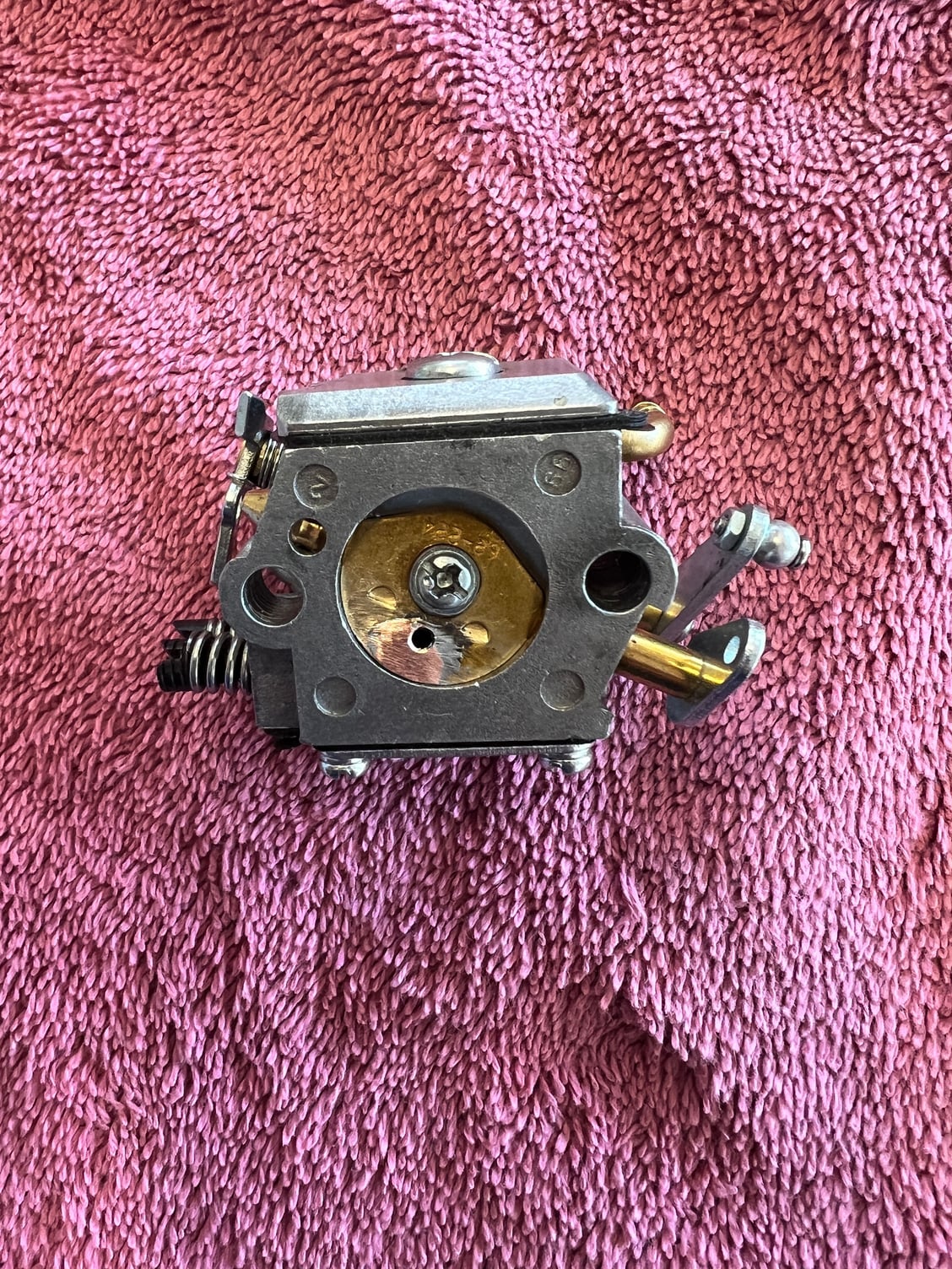
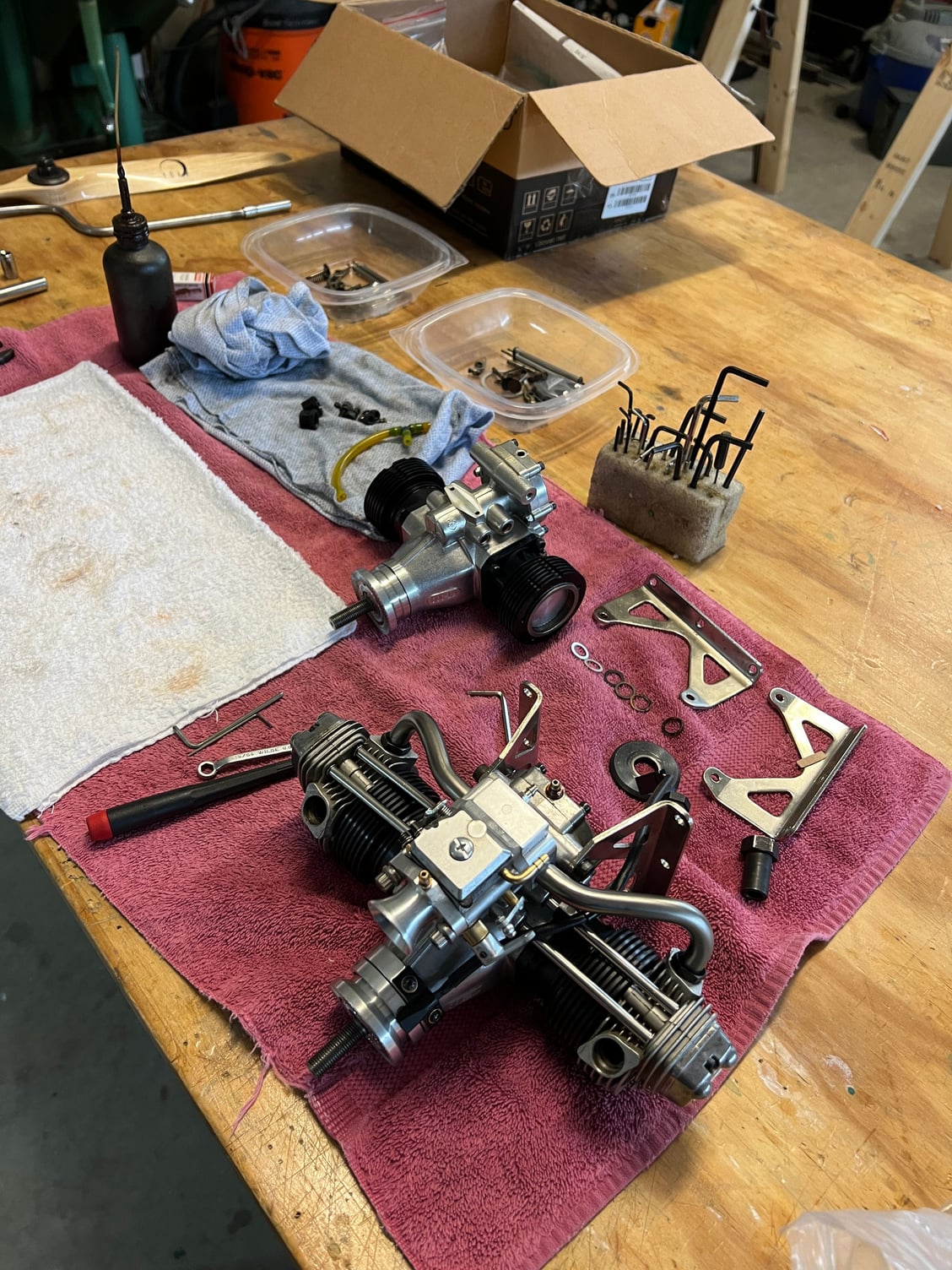
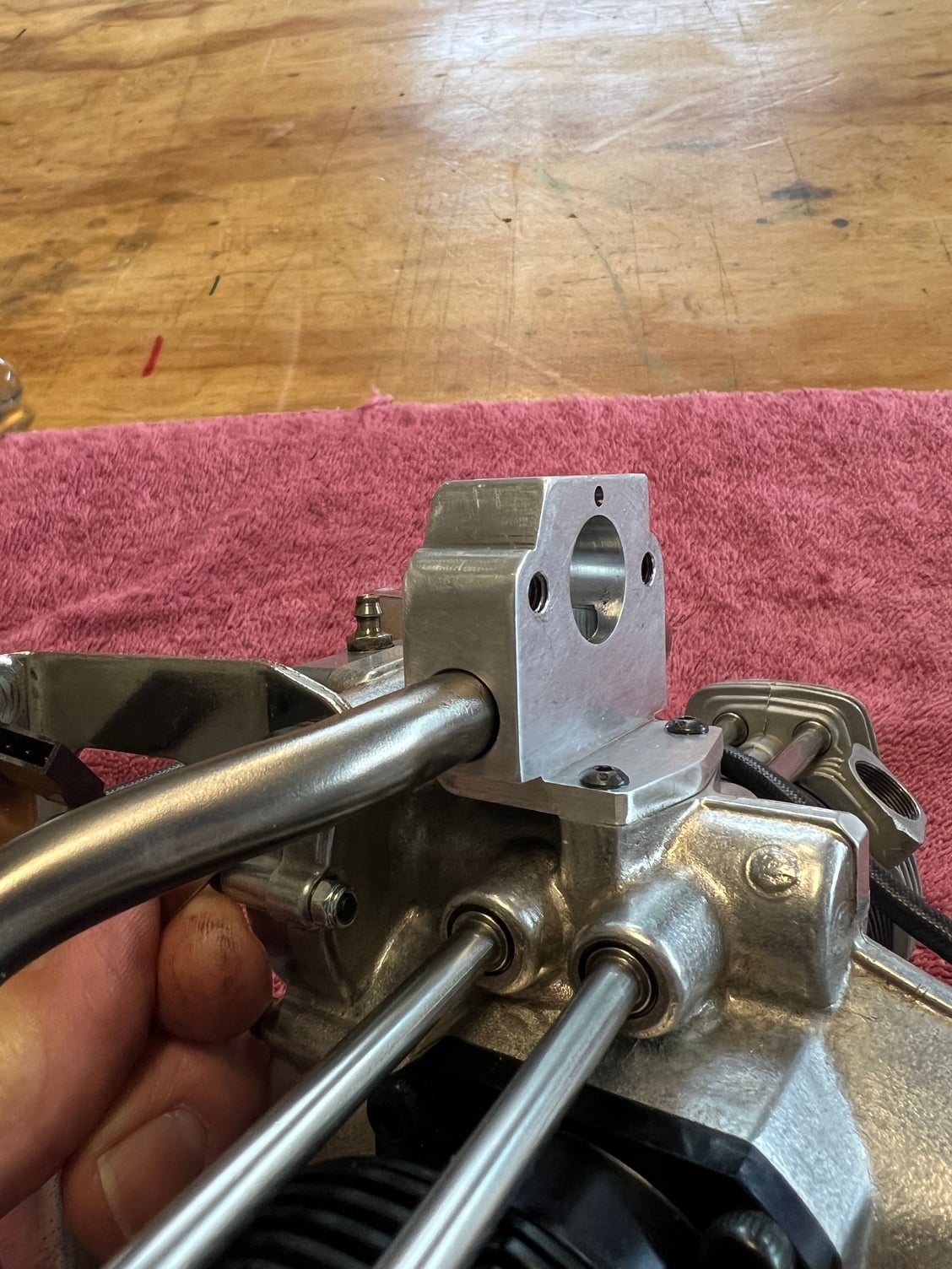
While I was waiting to see what you folks would toss into the mix I decided to try an "inlet charge diverter" first. I have little faith it will work but it is a place to start. Maybe I will combine this with Brutus' mesh vaporizer? You will see that it does have Glowgeek's radiused flow path now.
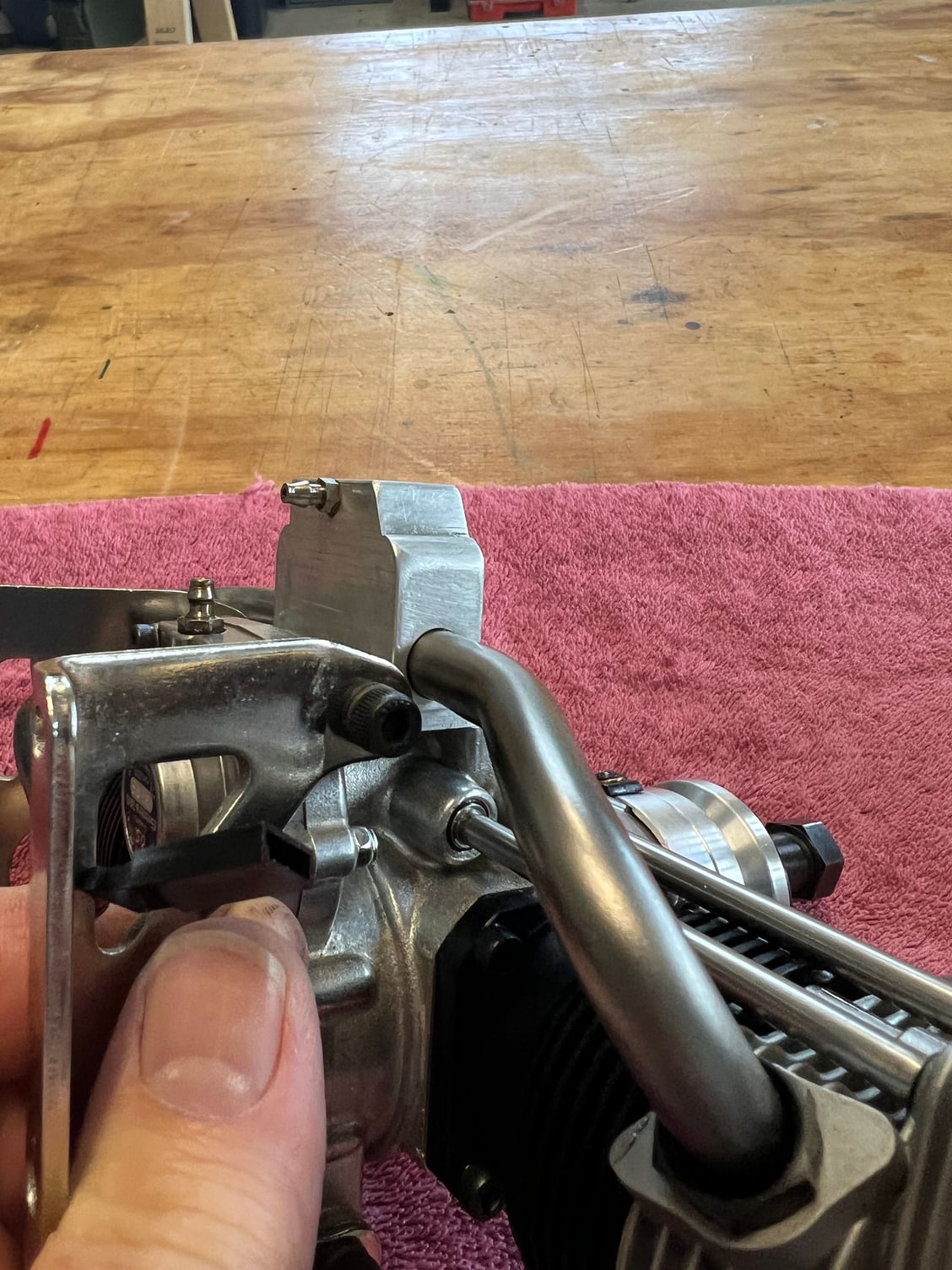
Let me start off by saying that even the stock, nitro-powed version of this series of engines (the 160 and the 300) act the same with regard to uneven mixtures between cylinders. The right is aways leaner/hotter than the left. My guess is that this is because no, the intake pipes are not the same length. I also wondered how this manifold with its 90 degree turn of the inlet charge would work compared to the straight thru flow of my little Gemini manifold and they seem identical - that is to say neither one is ideal!
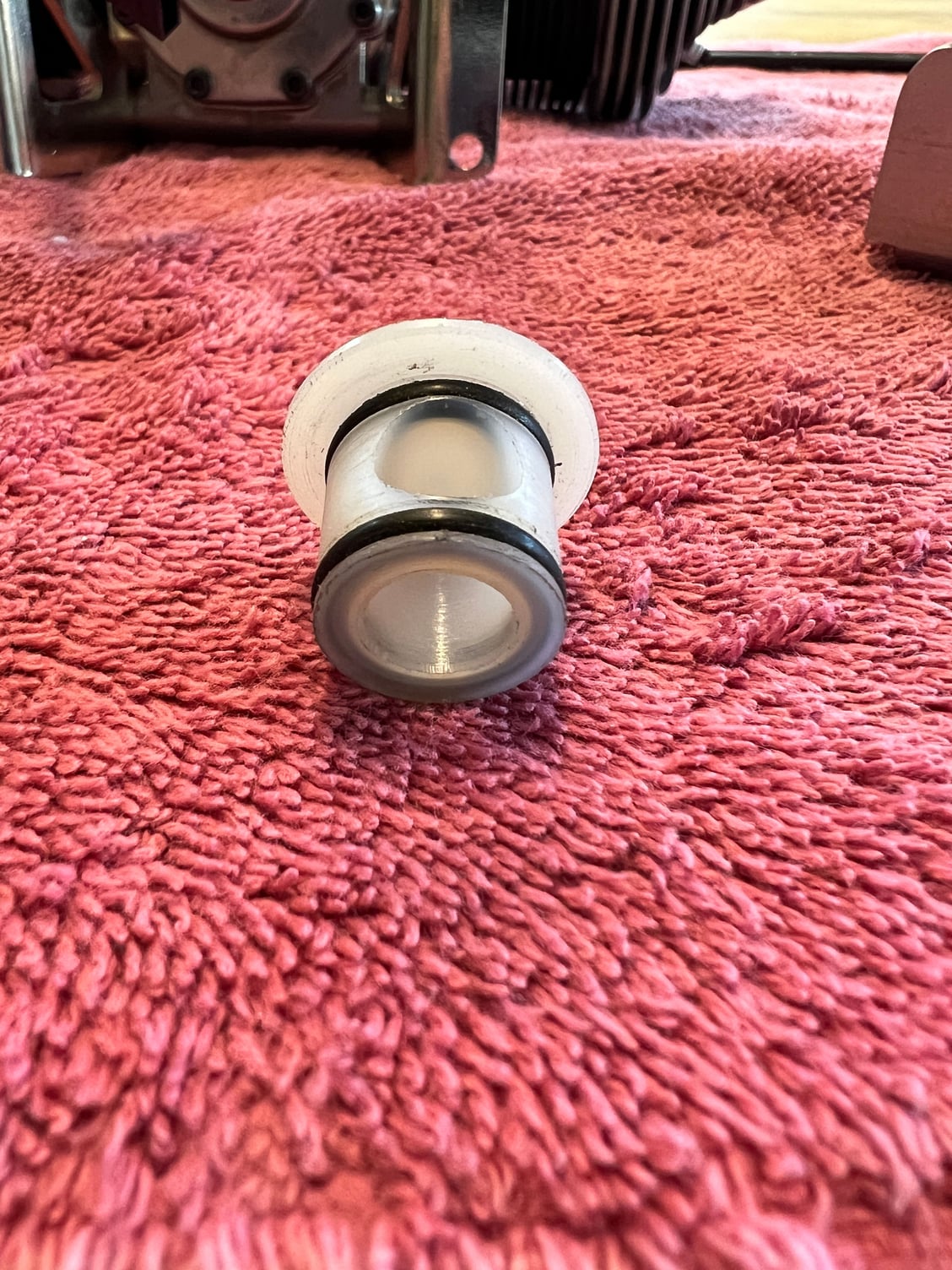
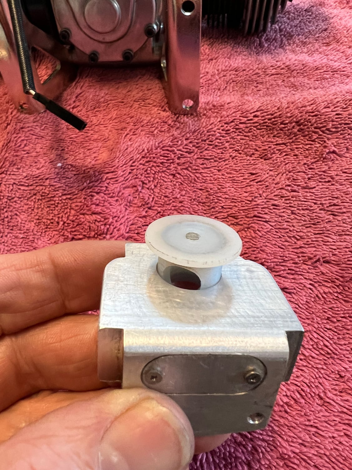
So: you will see I made a rotatable barrel out of nylon (might be Delrin) to "aim" the inlet charge toward one pipe or the other. I used a ball mill to plunge the holes so the back of the flow path would be radiused. I'm starting off with the flow path pointed as far toward the right (lean) cylinder as it will go. My thinking is, the inlet charge will be able to flow smoothly to that lean cylinder but it will have to follow more than a 90 degree turn to get to the left cylinder. A LOT more than 90 degrees really. Not only that but the charge to that rich cylinder will have to flow past the knife edge of the barrel hole to get there. I'm thinking this HAS to make a difference.
Like I said, I'm starting with the barrel biased as far "rich to the right" as I can get. Maybe I'll get lucky and will have to rotate it a little to the left to equalize the flow. The beauty is it's infinitely adjustable.
So what do you guys think? Is it going to work? Personally, I wouldn't bet the farm on the outcome! One way or the other it's going to be an interesting experiment . . . .

Flow path is radiused thanks to the ball end mill.
You can see how there's nearly a knife edge the charge will have to navigate to go left (which is to the right in this pic)

I put a (ok, somewhat crude) red indicator line so I could see the position. Full "rich right" right now.
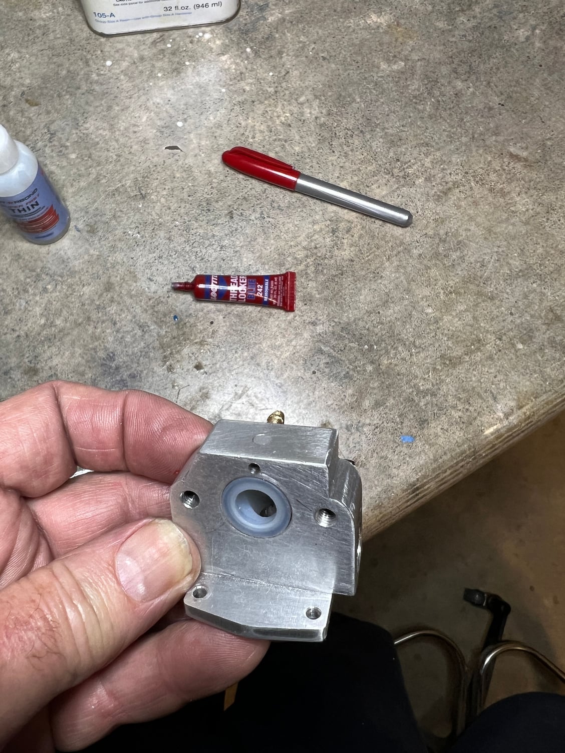
You may have to expand the next two pics to see the flow path inside.
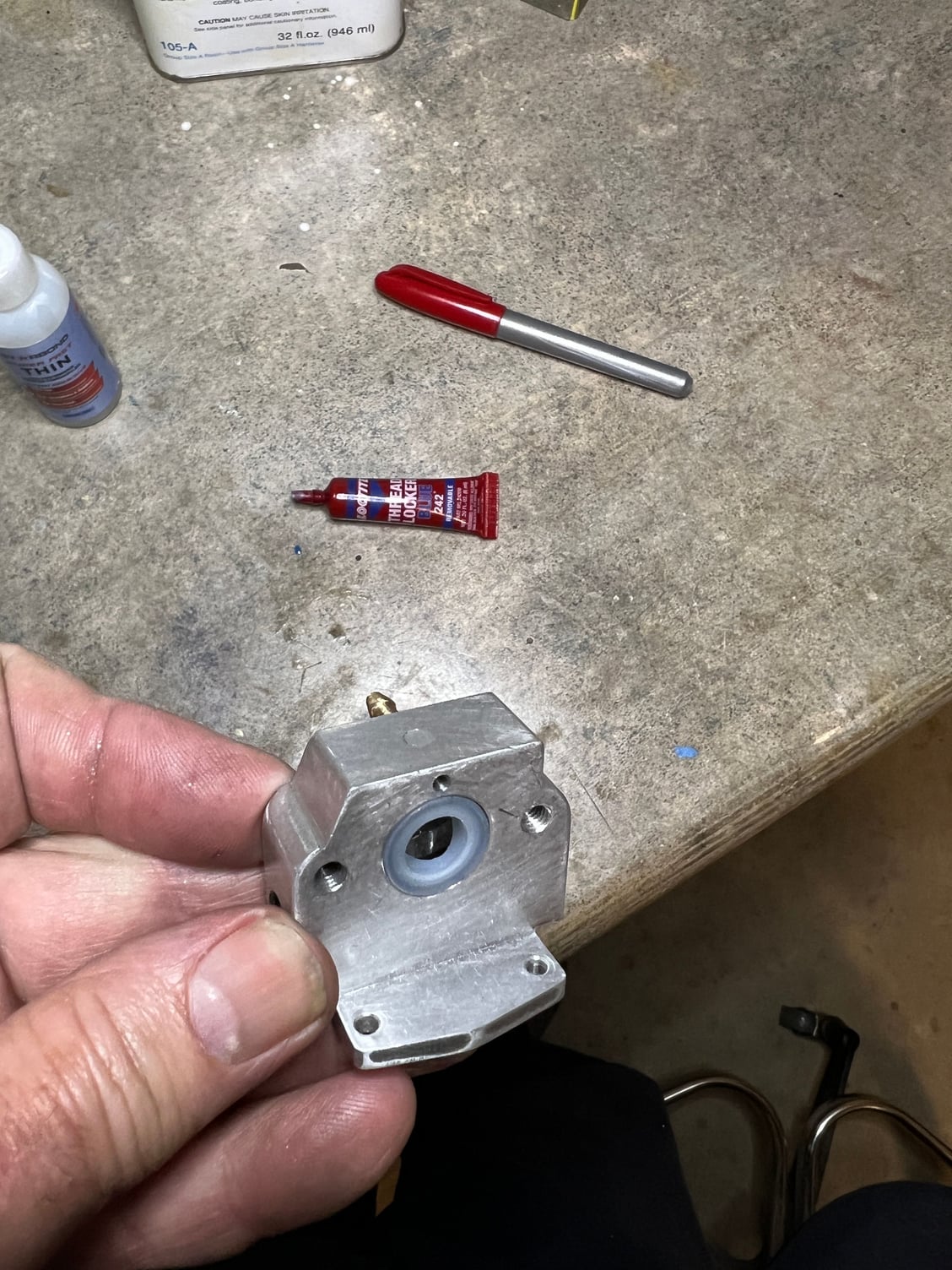
Should be interesting!
While I was waiting to see what you folks would toss into the mix I decided to try an "inlet charge diverter" first. I have little faith it will work but it is a place to start. Maybe I will combine this with Brutus' mesh vaporizer? You will see that it does have Glowgeek's radiused flow path now.
Let me start off by saying that even the stock, nitro-powed version of this series of engines (the 160 and the 300) act the same with regard to uneven mixtures between cylinders. The right is aways leaner/hotter than the left. My guess is that this is because no, the intake pipes are not the same length. I also wondered how this manifold with its 90 degree turn of the inlet charge would work compared to the straight thru flow of my little Gemini manifold and they seem identical - that is to say neither one is ideal!
So: you will see I made a rotatable barrel out of nylon (might be Delrin) to "aim" the inlet charge toward one pipe or the other. I used a ball mill to plunge the holes so the back of the flow path would be radiused. I'm starting off with the flow path pointed as far toward the right (lean) cylinder as it will go. My thinking is, the inlet charge will be able to flow smoothly to that lean cylinder but it will have to follow more than a 90 degree turn to get to the left cylinder. A LOT more than 90 degrees really. Not only that but the charge to that rich cylinder will have to flow past the knife edge of the barrel hole to get there. I'm thinking this HAS to make a difference.
Like I said, I'm starting with the barrel biased as far "rich to the right" as I can get. Maybe I'll get lucky and will have to rotate it a little to the left to equalize the flow. The beauty is it's infinitely adjustable.
So what do you guys think? Is it going to work? Personally, I wouldn't bet the farm on the outcome! One way or the other it's going to be an interesting experiment . . . .
Flow path is radiused thanks to the ball end mill.
You can see how there's nearly a knife edge the charge will have to navigate to go left (which is to the right in this pic)
I put a (ok, somewhat crude) red indicator line so I could see the position. Full "rich right" right now.
You may have to expand the next two pics to see the flow path inside.
Should be interesting!
Last edited by mitchilito; 03-20-2023 at 02:50 AM.
03-20-2023, 03:19 AM
#99
Your idea might work. There is no denying that these things have unequal distribution, and there is no denying that ANY changes to the intake system WILL have effect.
I found that for my own very crude attempts, the issue being in the "tunability" of those changes. More specific that the same change will have a different effect at different throttle settings or different RPMs.
What I however DID learn is the following.After leaving the carb, fuel evaporates, oil does not. This is NOT an instant proces, it takes time. Rather miliseconds than seconds, but time is time (ask any businessman and he will tell you that time is money, but alas...)
Immediately after the carb the oil droplets contain more fuel than further on towards the cylinder. Vapour distributes evenly, liquid does not. The liquid part of the mixture is what causes one cylinder to go leaner than the other.
Ergo: you can try to distribute the liquid part of the mixture better, OR you can try to promote evaporation.
In your case; why not try both?
The mesh "holds up" the liquid, giving it both more surface area AND more time to evaporate. Your deflector will distribute whatever liquid is left more evenly.
Trying them separately first, to see which remedy does what exactly, will be extremely educational...
EDIT; I see you return the crankcase effluent back to the air intake. I can see the reason why people might want to do that, but I have poor experiences with that: Because the oil does not return as a real mist, but rather as coarser droplets, it caused irregular running in the one engine that had that (my 91 FS single).
I also do not see any benefit from recirculating combustion residue and wear particles through the engine a 2nd time (or a third, or a fourth, until it finally finds its way to the exhaust valve). IMHO, once through is enough.
Last edited by 1967brutus; 03-20-2023 at 03:30 AM.
03-20-2023, 03:27 AM
#100
I cannot speak for others, but for me, that mainly has to do with that your "little project" is not as little as you seem to think, but aside from that also because same like your 160 conversion earlier... it is so darned beautifully executed, if you don't mind me saying.
The following users liked this post:
mitchilito (04-03-2023)