


JW Büker Jungmeister build
 01-17-2022, 01:08 PM
#26

Finished the vertical surfaces today. Too bad I didn't know at the beginning of this kit build what I know now. It came out great. Once again I will note that ALL balsa I used on this part of the build was not in the kit. I used 1/16 balsa throughout.
The rudder ready for sanding. I used whatever balsa I had kicking around to build this up! Just know this: the first sticks go fully between the ribs. the rest have to allow for the hinges.
Sanded down to the rib leading edges
Done!
Once you get used to this build technique it gets to be fun.
Happy with the outcome.
Last edited by mitchilito; 01-17-2022 at 03:21 PM.

The following users liked this post:
Steve (05-12-2022)
01-19-2022, 10:41 AM
#27
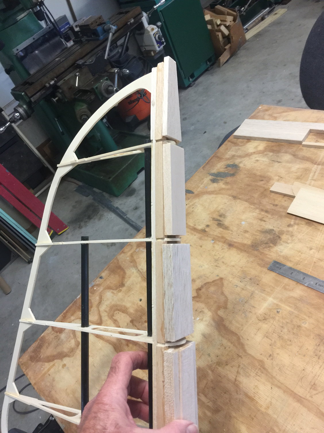
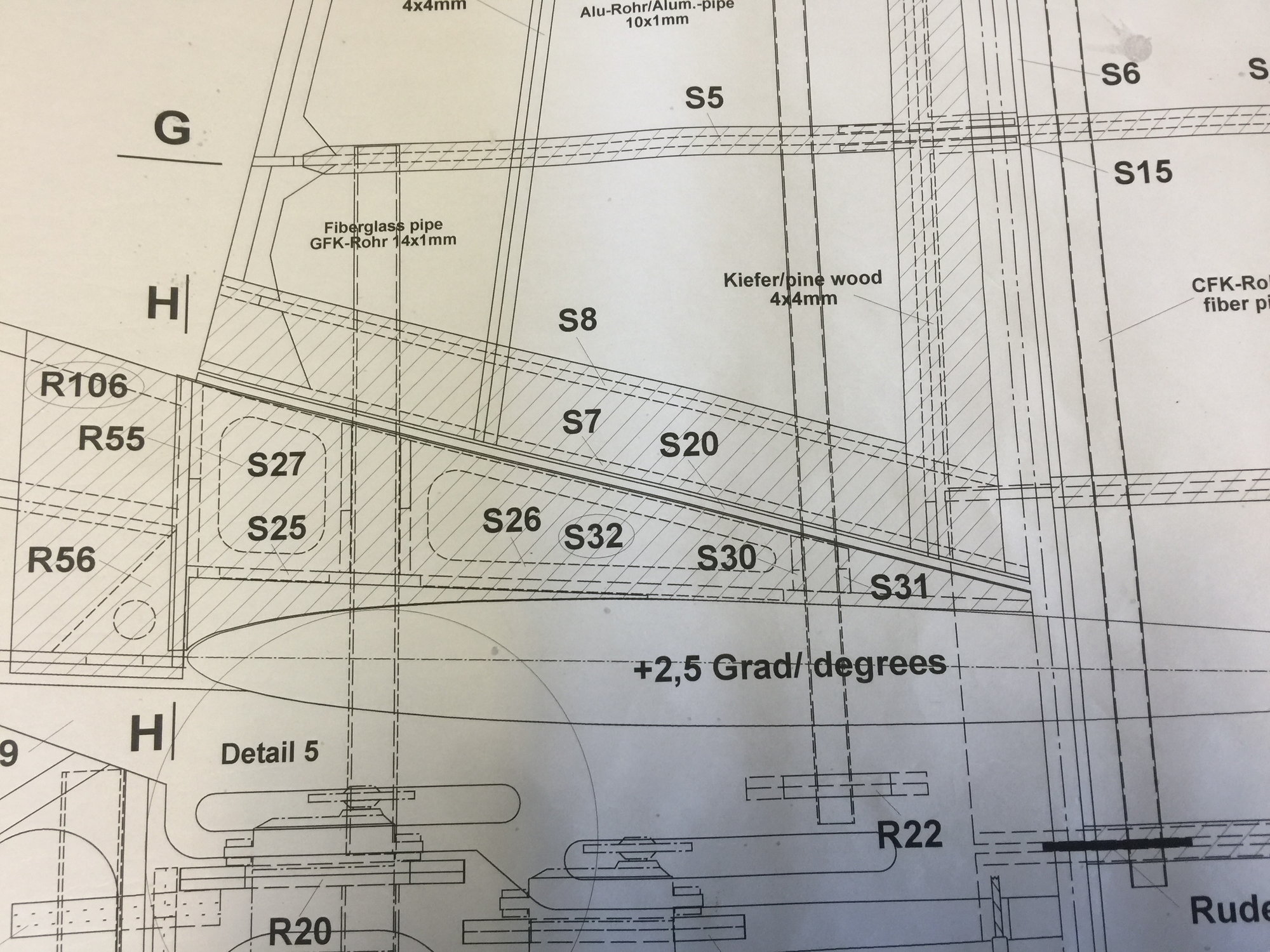
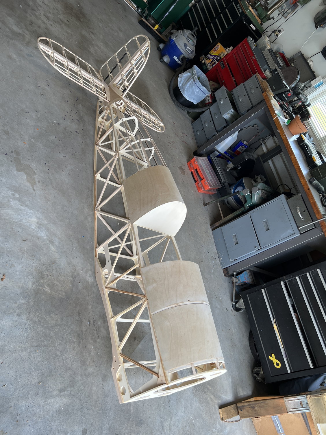
So I built this kit slightly out of order. Instructions say wings, center sections, Rudder, then stab. The rudder looked a little more complicated (tapering geometry) so I built the H-stab first.
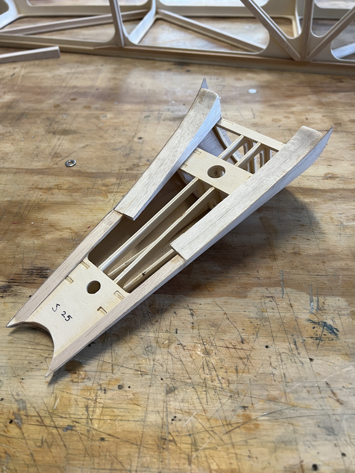
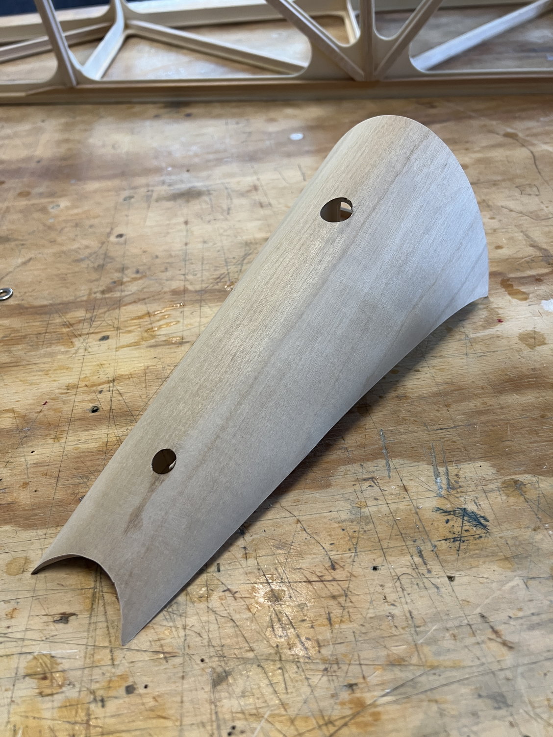
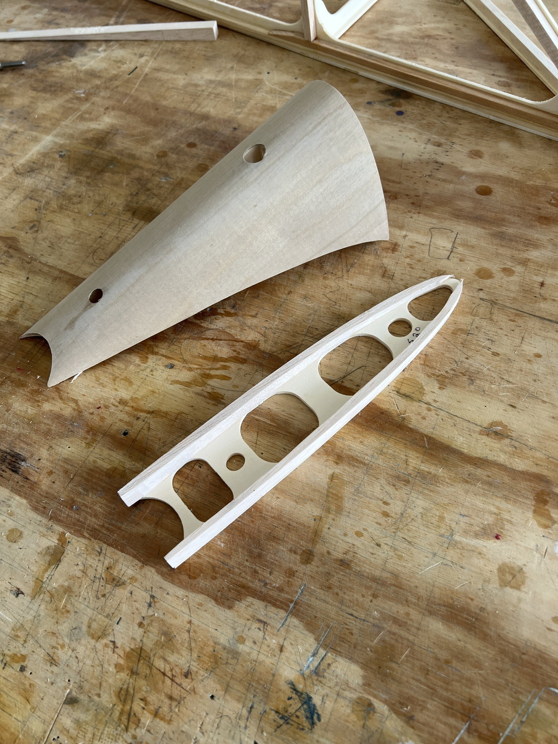
The point being, they have you build the rudder early on and at the end of the rudder build they instruct you to build the "rudder fairing" which is the section were the fuselage transitions through the tail surfaces to the very back of the fuselage. In the past, when tackling this process on other kits I have devised some kind of crafty method to make sure it comes out looking good. For this kit I have zero idea how to make this thing and especially how to make it look professional. I'll annotate the pictures for further discussion.
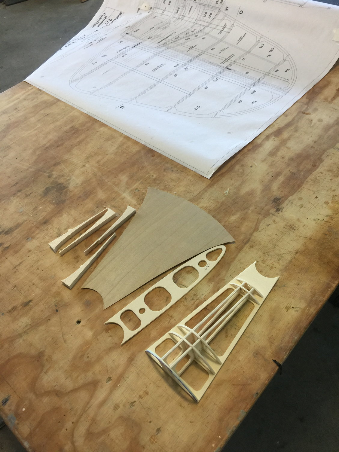
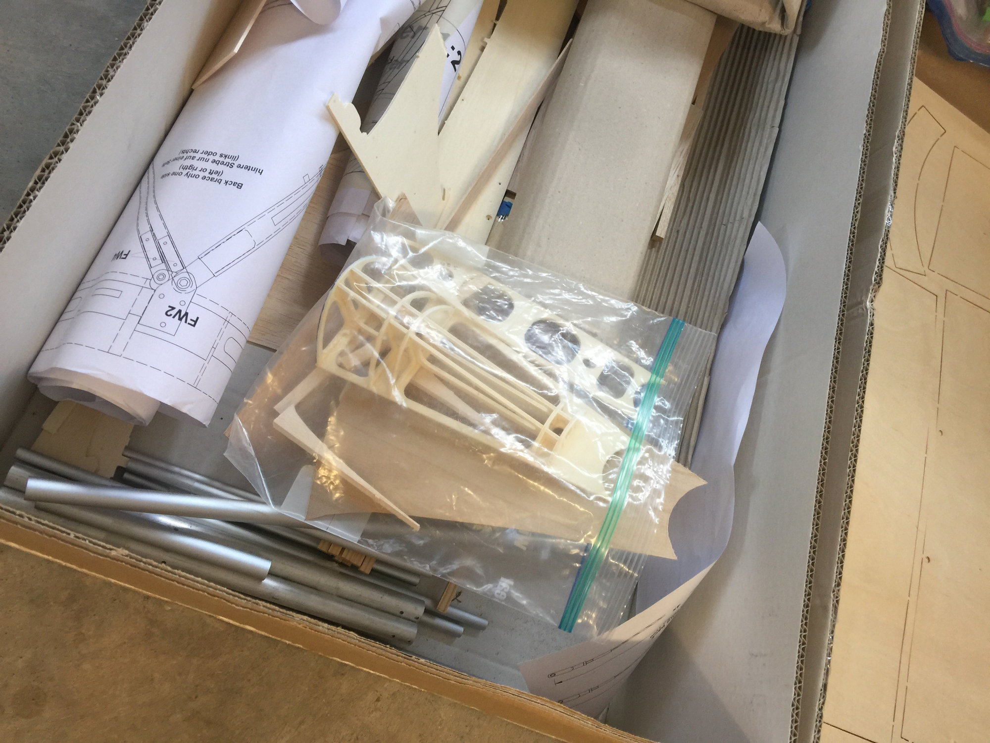
Here are the parts. The framed part is really cool. CNC designs do have distinct advantages.
The rib on top is just sitting there. I'm presuming once the frame is sheeted with the .8mm ply the idea is to glue that rib to the top and fair the whole mess with (what the plans call "left over") balsa. Yeah, right.
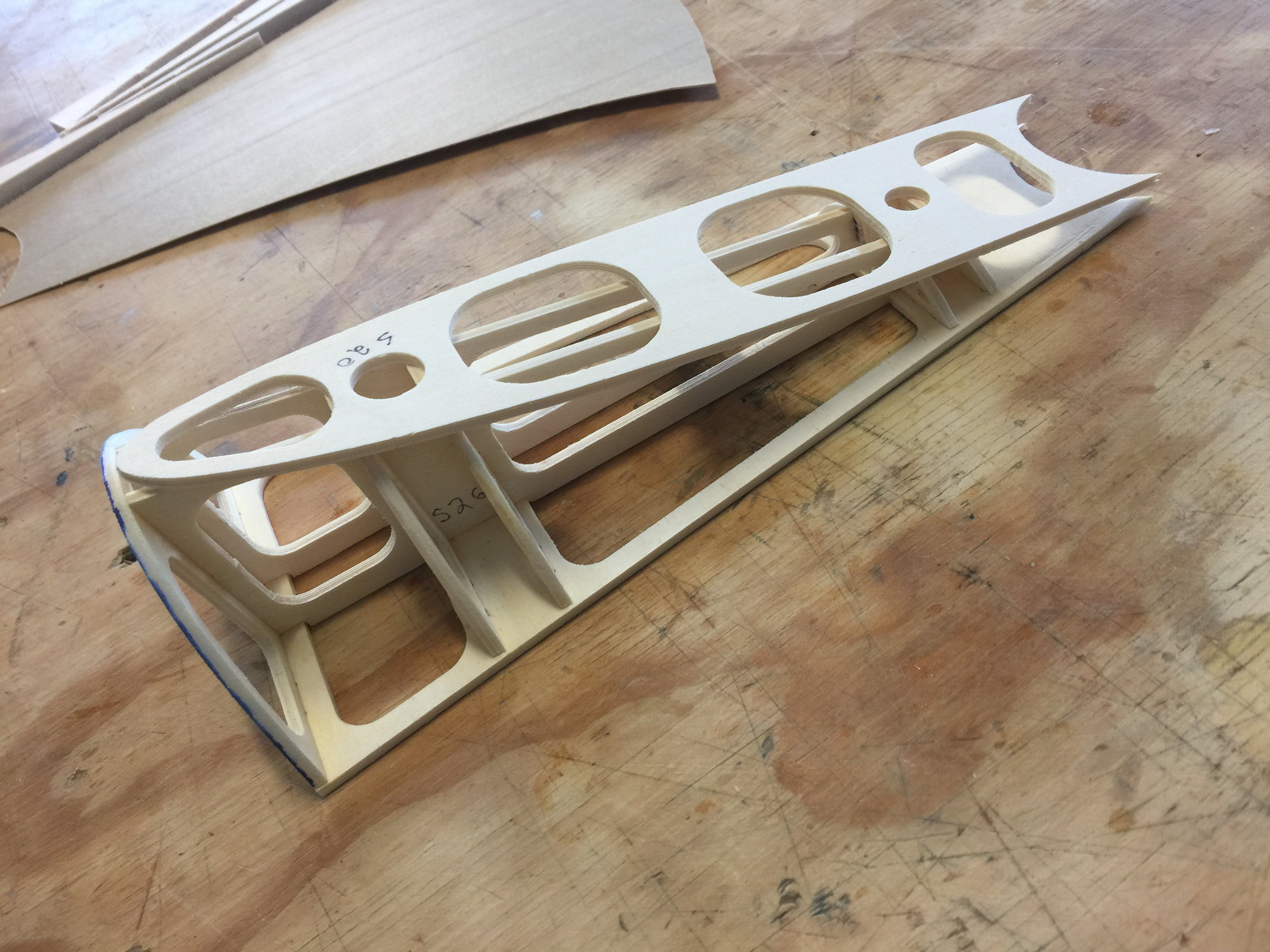
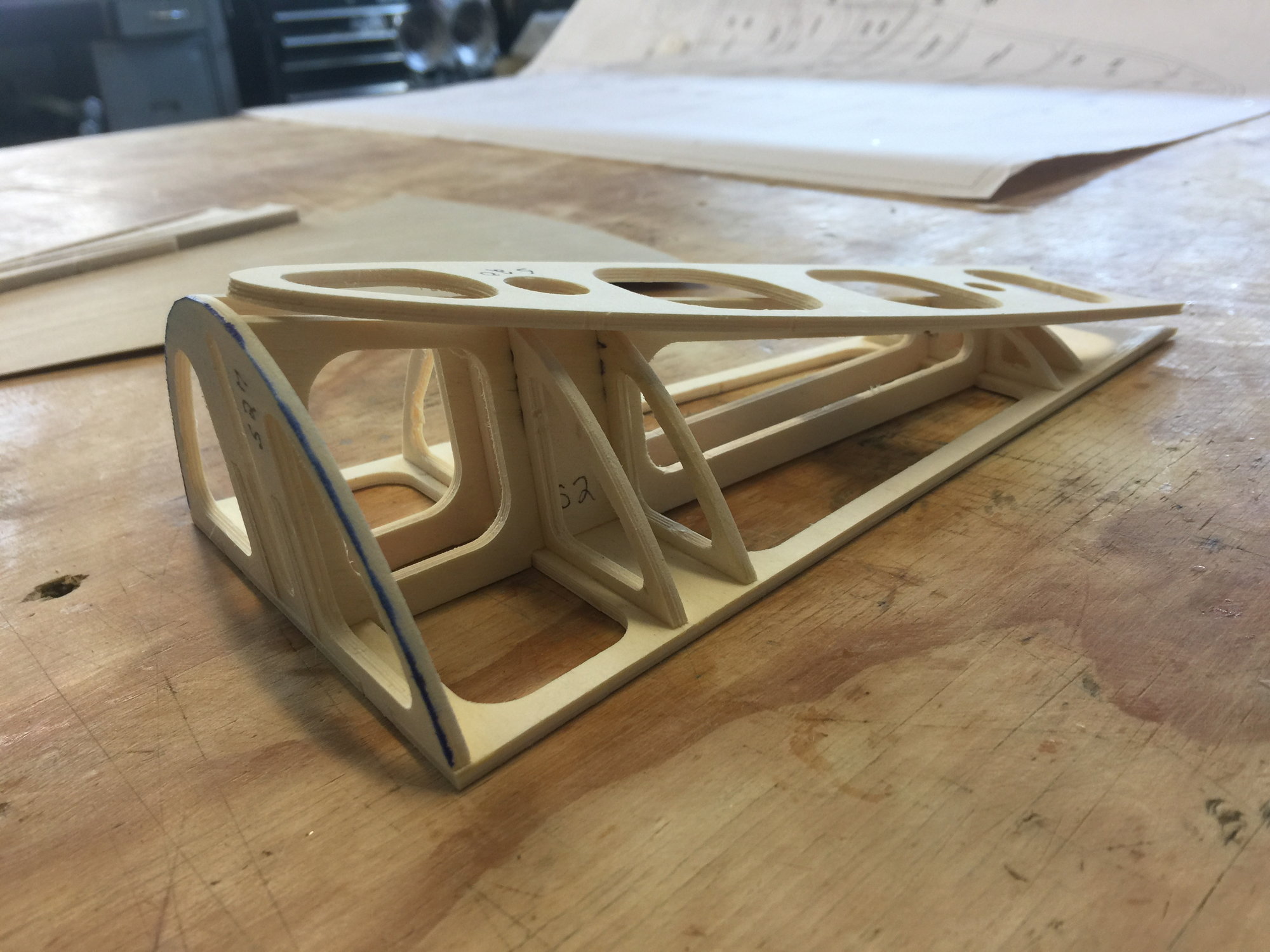
There is simply no way to build this part without the V-stab, H-stab and the fuselage present to fit it all together. So in the kit box it goes until I have the fuselage to a stage where this is do-able
And here it will stay until I have the fuselage to mate it - and the tail feathers - to.
The point being, they have you build the rudder early on and at the end of the rudder build they instruct you to build the "rudder fairing" which is the section were the fuselage transitions through the tail surfaces to the very back of the fuselage. In the past, when tackling this process on other kits I have devised some kind of crafty method to make sure it comes out looking good. For this kit I have zero idea how to make this thing and especially how to make it look professional. I'll annotate the pictures for further discussion.
Here are the parts. The framed part is really cool. CNC designs do have distinct advantages.
The rib on top is just sitting there. I'm presuming once the frame is sheeted with the .8mm ply the idea is to glue that rib to the top and fair the whole mess with (what the plans call "left over") balsa. Yeah, right.
There is simply no way to build this part without the V-stab, H-stab and the fuselage present to fit it all together. So in the kit box it goes until I have the fuselage to a stage where this is do-able
And here it will stay until I have the fuselage to mate it - and the tail feathers - to.
Last edited by mitchilito; 01-19-2022 at 10:44 AM.
The following users liked this post:
Steve (05-12-2022)
The following users liked this post:
Steve (05-14-2022)
03-17-2022, 08:56 AM
#30
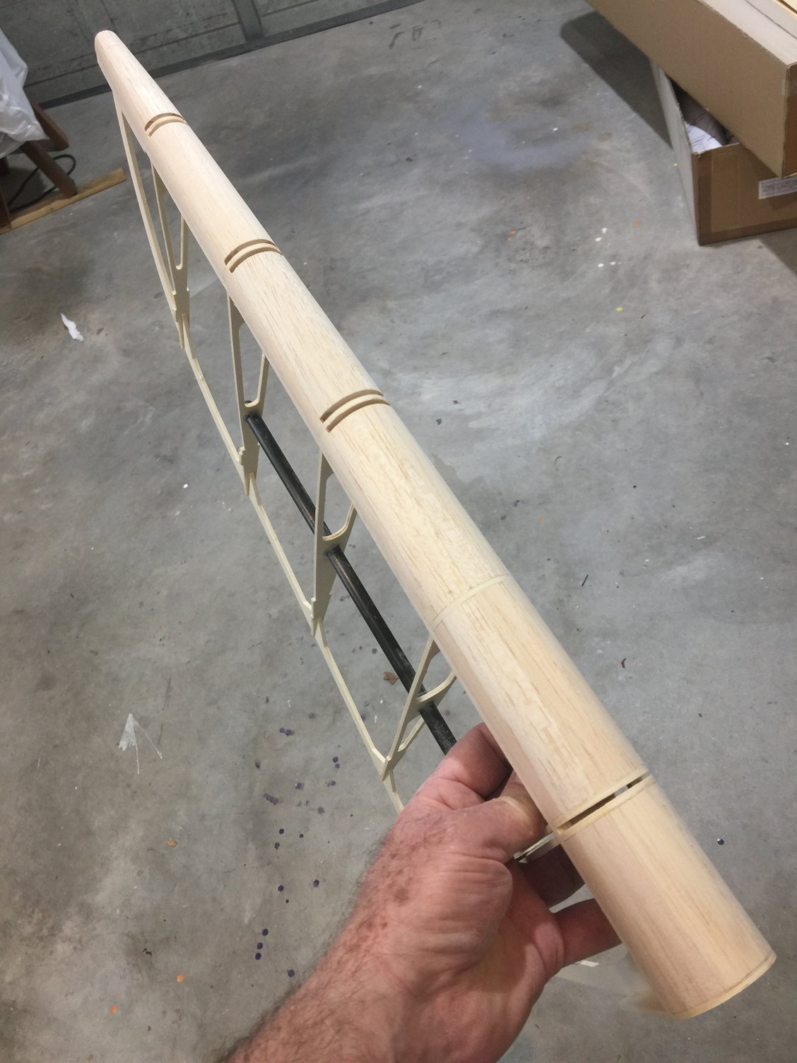
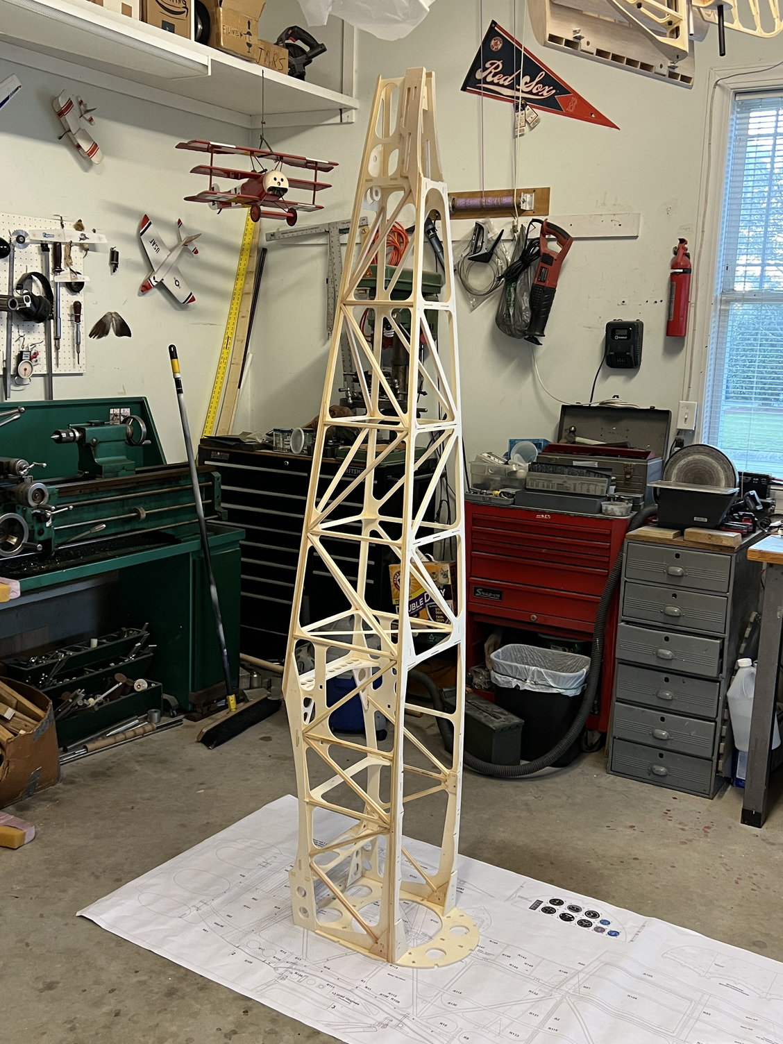
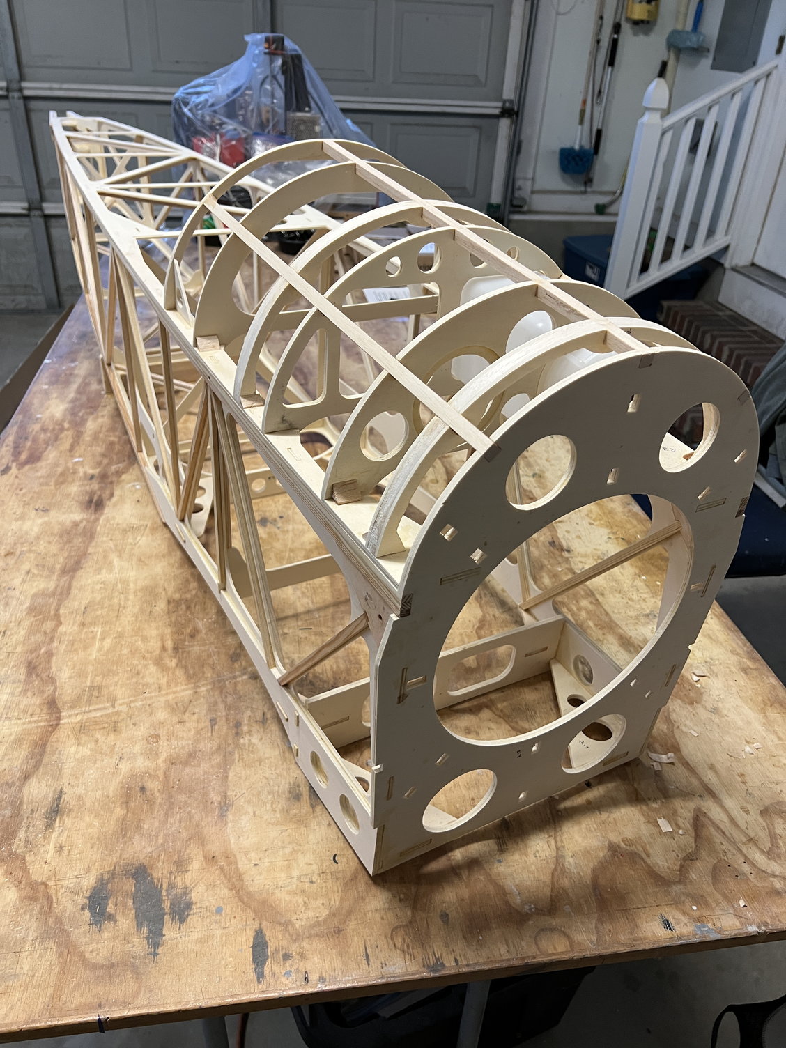
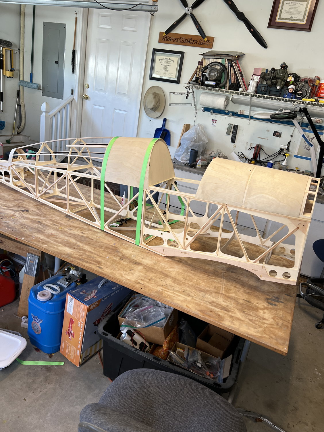
Like I said above, I've started on the fuselage. I have everything else built.
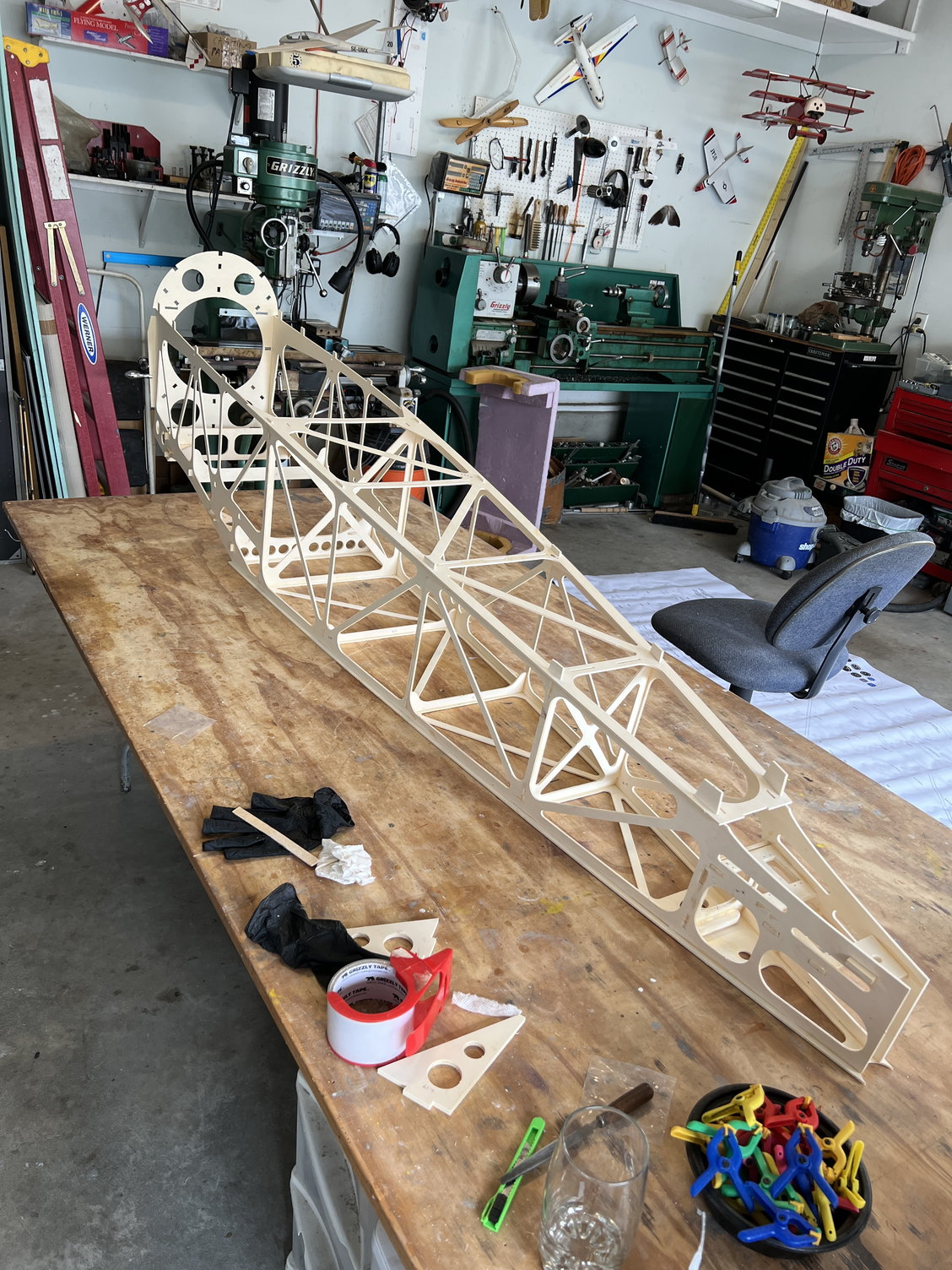
This part of the build is just like the rest of this interesting JW process: dry assemble everything to see how it all fits together, then figure out how to glue it all up. Here's there fuselage assembled without any glue:
This part of the build is just like the rest of this interesting JW process: dry assemble everything to see how it all fits together, then figure out how to glue it all up. Here's there fuselage assembled without any glue:
The following users liked this post:
Steve (05-12-2022)
03-17-2022, 09:15 AM
#31
It did not take long to run afoul of the plans/instructions. The plans tell you to "instal R20, R21 and R22 blah blah blah. . ." Well, here's the problem: there is no "R20". Only a R20A and R20B. R20 is the plywood platform that you mount the elevator servos to in the tail of the fuselage. There are lock tabs that key it into the fuselage sides and you laminate two of them to make one 1/4 inch plate. However, they provide 2 of each R20A and R20B and there's simply no way to use both sets. The 20As have lock tabs but no hole for the rudder spar tube. The 20Bs do not have the key tabs but do have the proper size spar tube holes! Yet again I will say, it would be so easy for JW to correct this (and all the other) oversights and make this build a lot more pleasant! Ok, I'm stepping off my soapbox now.
I could not see any use whatsoever for the tabless 20Bs so I used them to locate the spar tube hole on the 20As and installed the 20As. You will see what I mean when you get there. . . . .
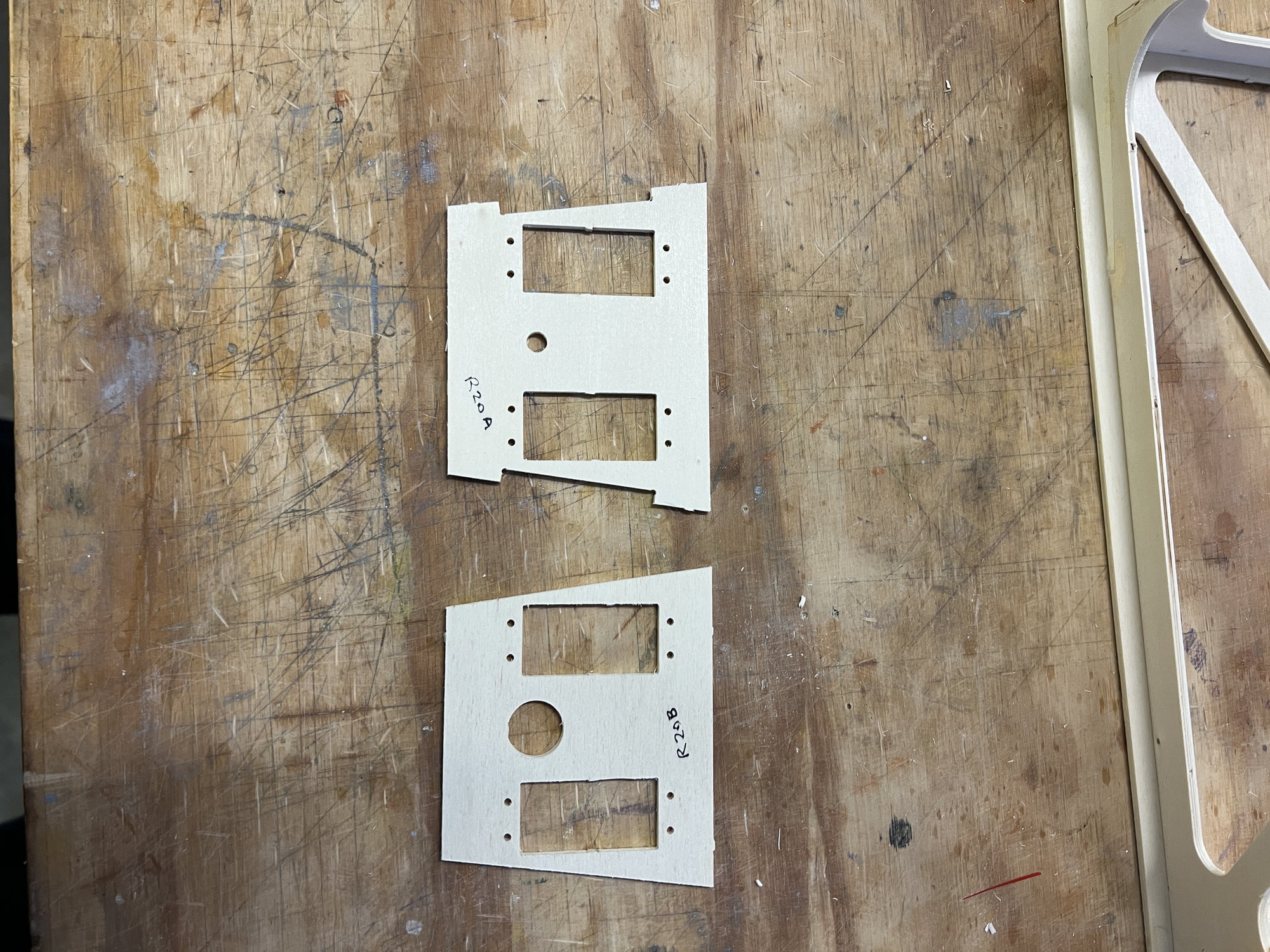
Who knows, maybe later in the build I see where the R20Bs where supposed to go but I seriously doubt it.
I could not see any use whatsoever for the tabless 20Bs so I used them to locate the spar tube hole on the 20As and installed the 20As. You will see what I mean when you get there. . . . .
Who knows, maybe later in the build I see where the R20Bs where supposed to go but I seriously doubt it.
The following users liked this post:
Steve (05-12-2022)
The following users liked this post:
Steve (05-12-2022)
03-30-2022, 04:44 AM
#34
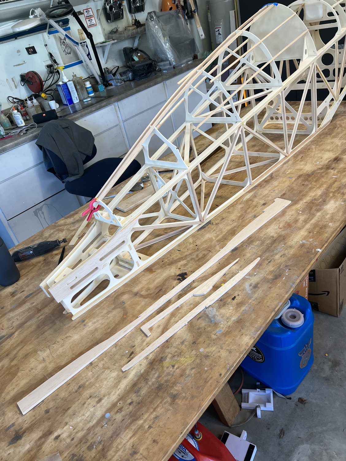
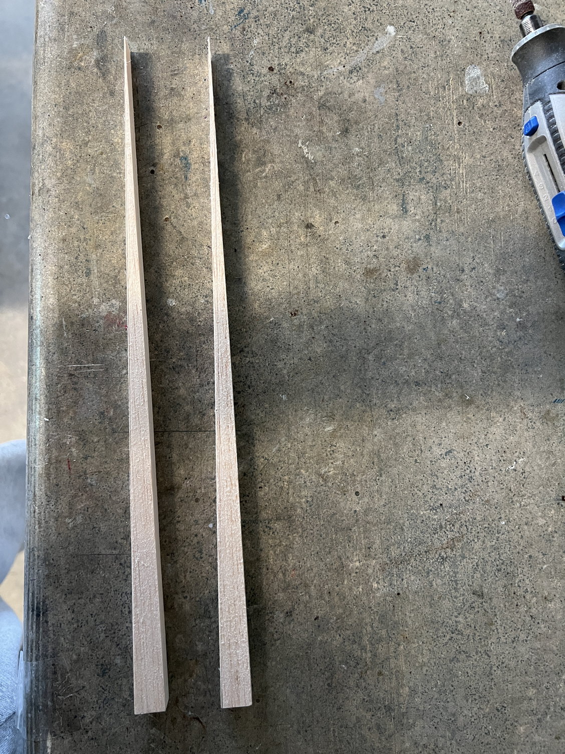
In keeping with the lack of enough wood in this kit, there were not enough hard wood sticks provided to complete all the bracing. Fortunately I had a piece of stock I could use to cut more out. I was about 2 feet short. Picture shows me cutting it out. Don’t know how I would’ve built this kit without a machine shop!
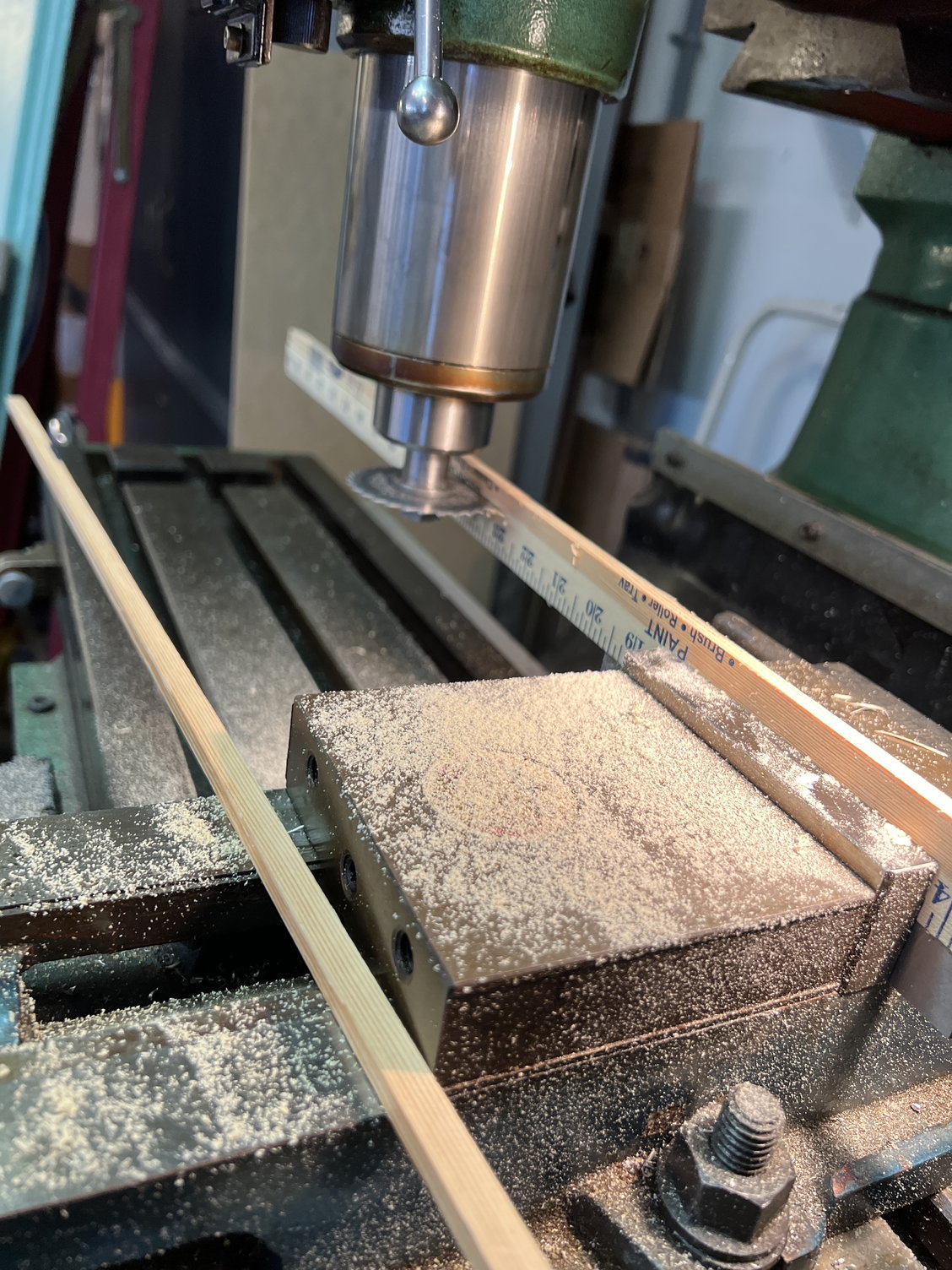
Yes, this started as a yard stick! But the hardwood was probably better then what the kit provided.
Yes, this started as a yard stick! But the hardwood was probably better then what the kit provided.
Last edited by mitchilito; 03-30-2022 at 04:47 AM.
03-30-2022, 04:55 AM
#35
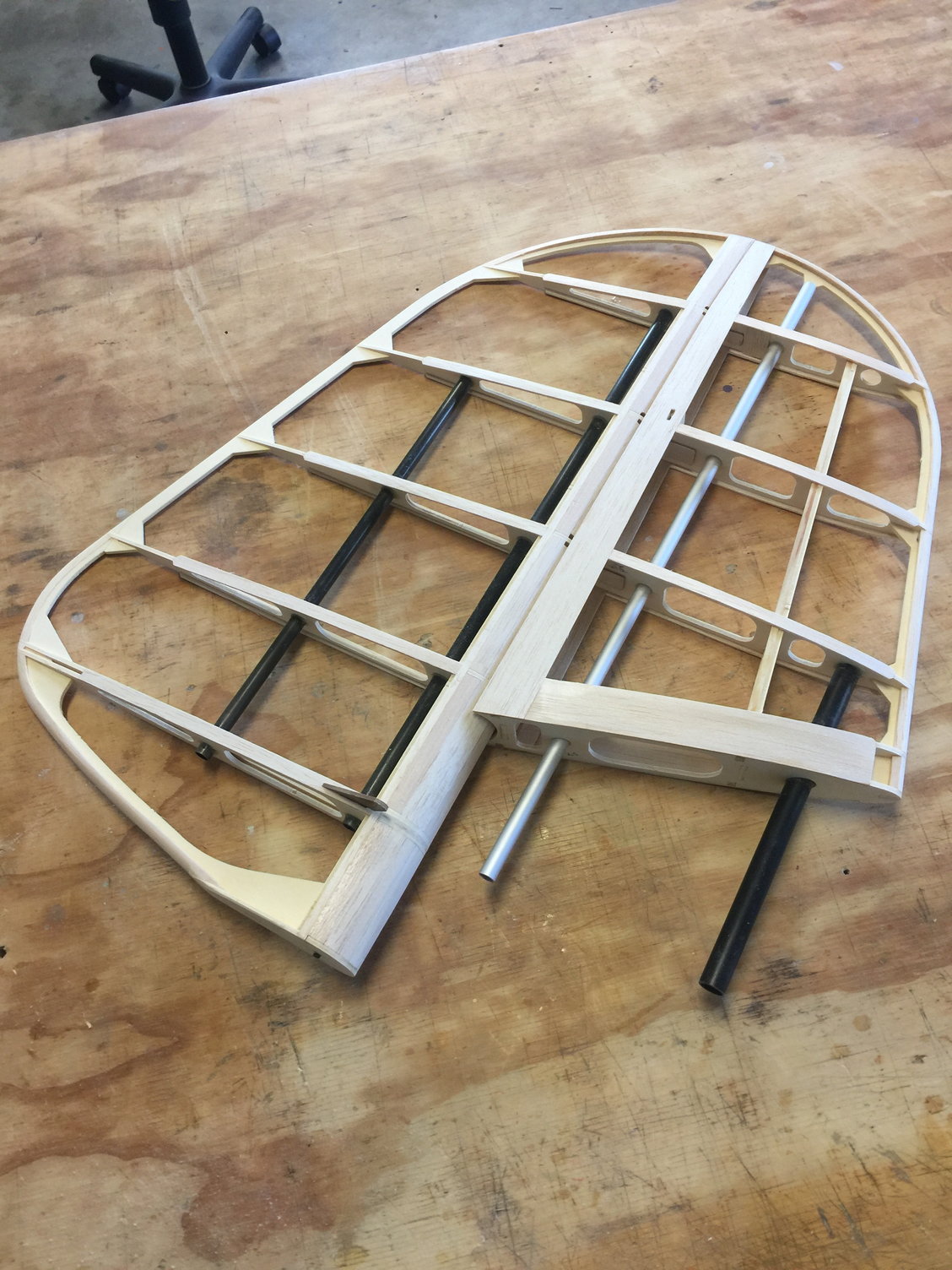
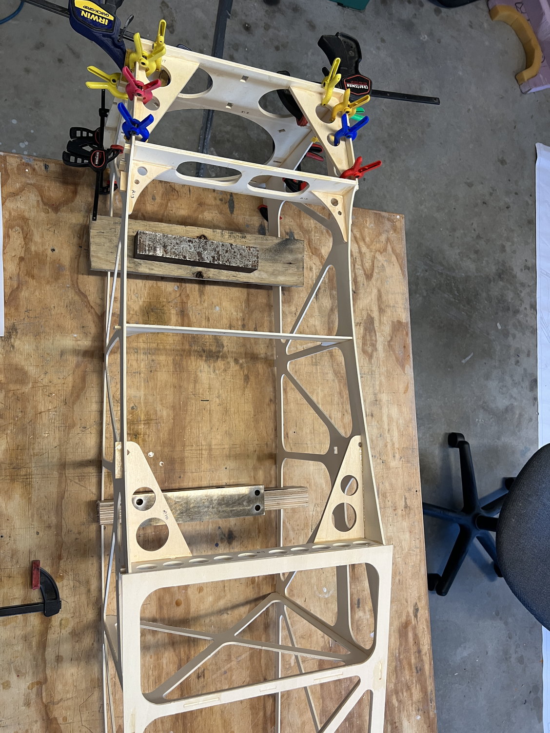
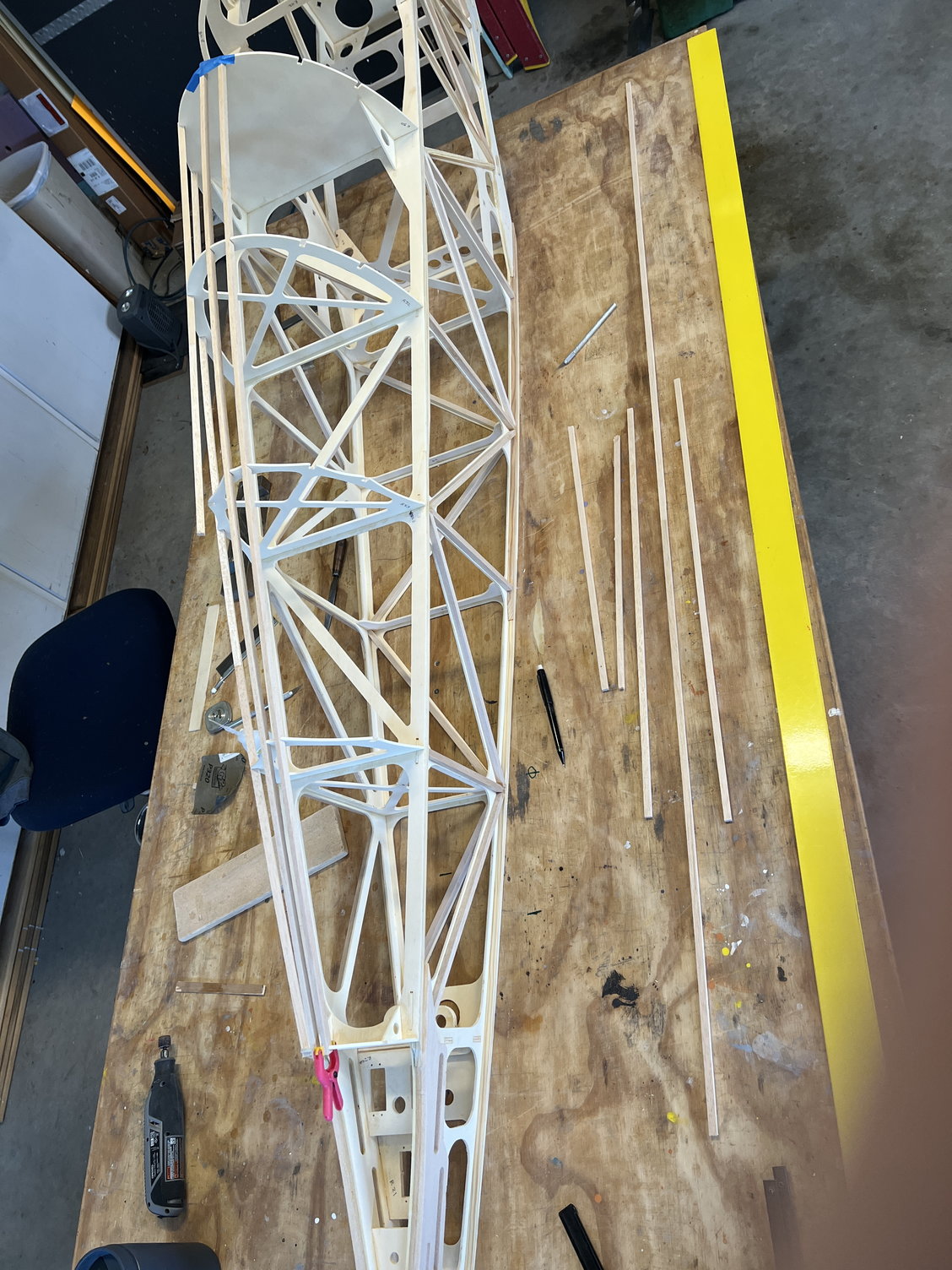
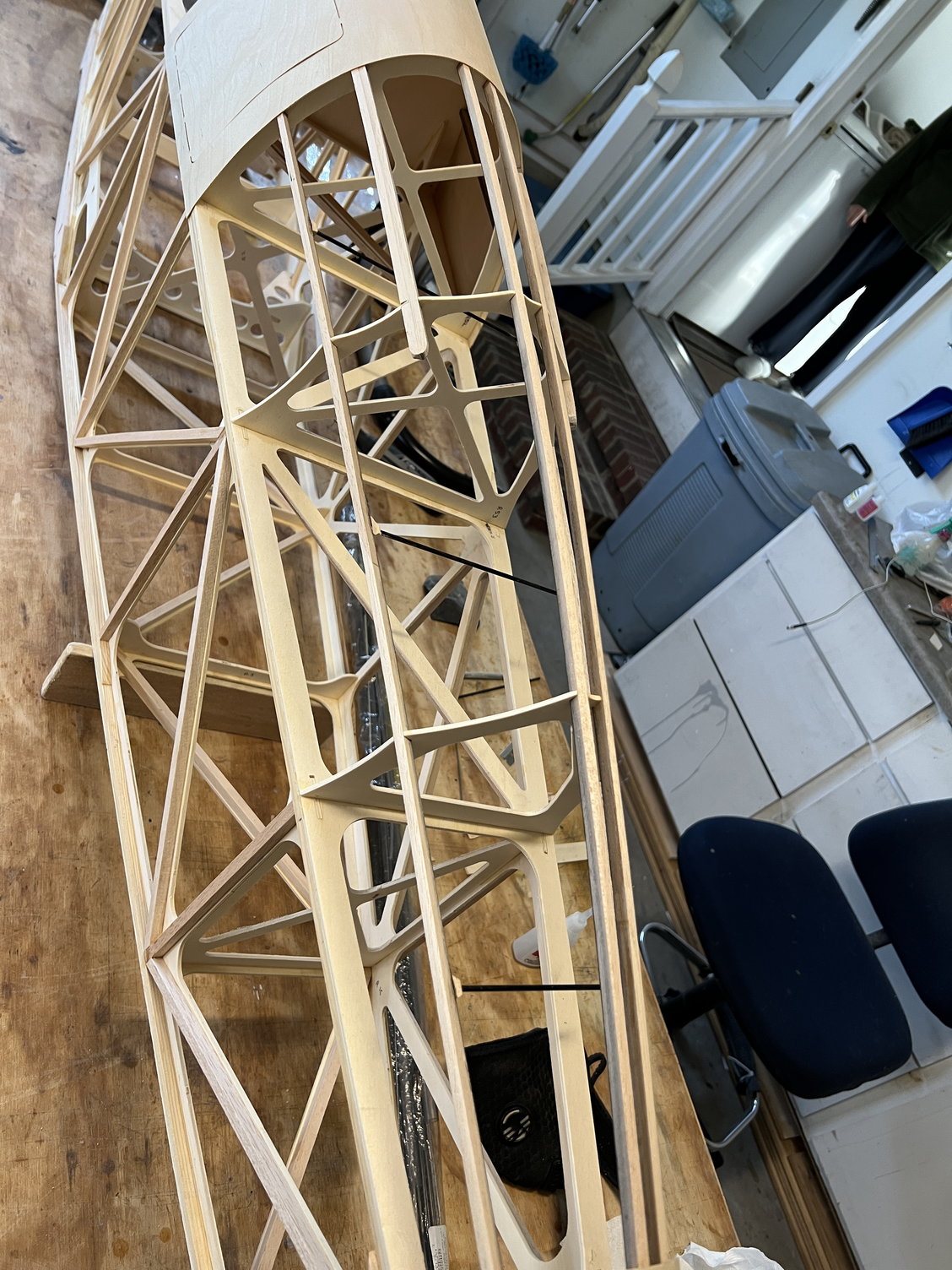
I deviated from the instructions in the order of fuselage construction. JW wants you to build the top section forward of the cockpit prior to installing the internal hardwood bracing. I thought that structure would be in the way and I was correct. Here’s the fully braced fuselage core.
The following users liked this post:
Steve (05-12-2022)
04-01-2022, 04:28 AM
#36
Now it was time for the top structures. This JW kit is interesting in many ways. It would seem simple at first glance, what with everything jig- locking together but it’s just not that simple.
The top forward structure is a good example. It was fairly easy to glue it all in place but that was only the beginning. Once glued on it has to be sanded/prepared for the sheeting. Since the ply sheet is so thin, the supporting structure needs to be perfectly aligned/smooth in all its many joints. This sanding/checking with a long straight edge/sanding etc. took a looooong time to get right.
You’ll notice I extended the side stringers all the way back to the instrument panel. The plans show otherwise but I couldn’t see a good reason not to. Again - more support for the super thin ply.
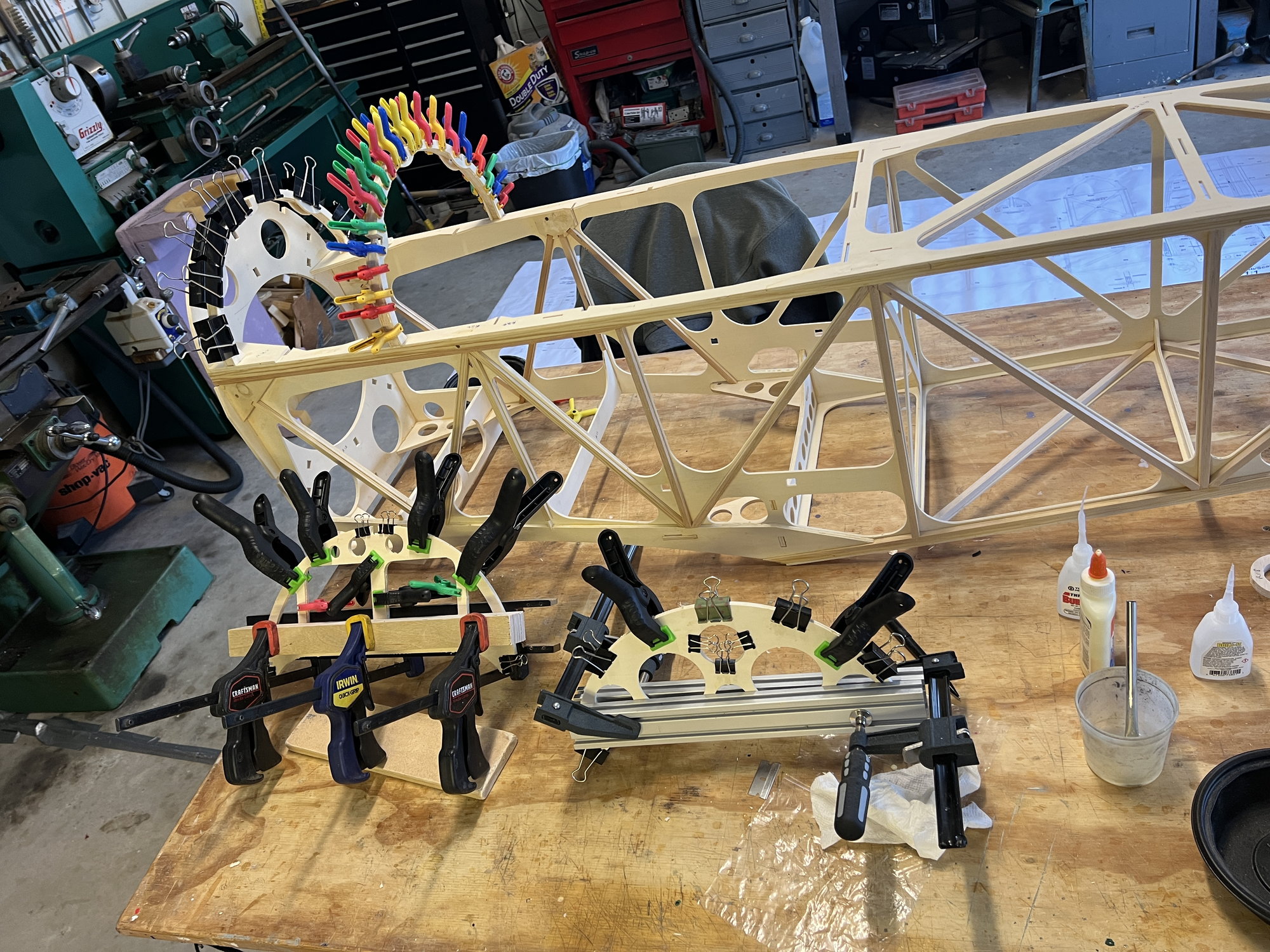
Last edited by mitchilito; 04-01-2022 at 05:39 AM.
The following users liked this post:
Steve (05-12-2022)
04-03-2022, 02:00 AM
#37
Moving on to the upper rear structure. I'm very glad I'm almost done with the rough build. No more dealing with lack of wood in the box. This time it was the balsa stringers for the back end. Almost 5 feet of 6x8mm stringer stock short! So I looked around in the scrap pile and found enough scrap to barely finish. The pictures show the scrap pieces before I cut them and then when I scarfed them together. What a mess!
Here's the scrap. I had to use every inch in the box - some of it not very suitable.
Here's how much I was able to cobble out of scrap. I know it's obvious by now but I was really really really disappointed by this. I literally didn't have one inch to spare!
Here's the scrap. I had to use every inch in the box - some of it not very suitable.
Here's how much I was able to cobble out of scrap. I know it's obvious by now but I was really really really disappointed by this. I literally didn't have one inch to spare!
The following users liked this post:
Steve (05-12-2022)
04-03-2022, 11:51 AM
#38
Plans say to put carbon roving on the backs of the turtle deck stringers but the kit didn’t have any. I had some heavy 1” carbon tape laying around so I stretched it out, saturated it with epoxy and set the stringers on it to cure. Worked okay I guess.
Last edited by mitchilito; 04-03-2022 at 11:55 AM.
The following users liked this post:
Steve (05-12-2022)
04-04-2022, 12:02 PM
#39
I used ratchet straps to help with the sheeting. Turned out to be the best way. You'll notice that the very front little sheeting strip is missing. It turned out to be too narrow. I'm going to have to make my own from-scratch piece. I think it will be a fiberglass part.
Last edited by mitchilito; 04-04-2022 at 12:05 PM.
The following users liked this post:
Steve (05-12-2022)
The following users liked this post:
Steve (05-12-2022)
05-10-2022, 04:39 AM
#41
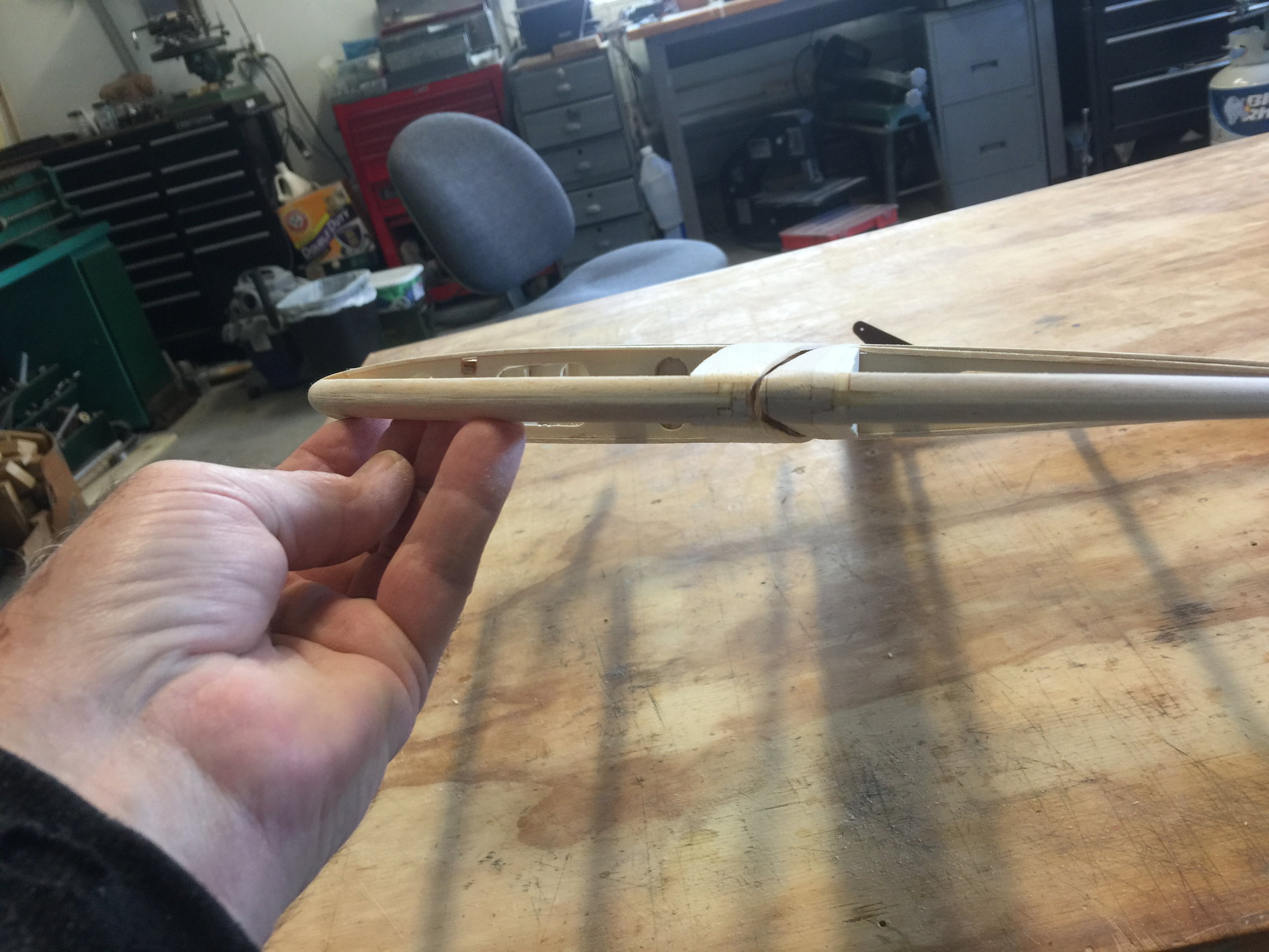
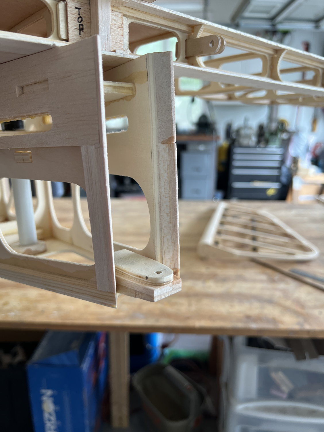
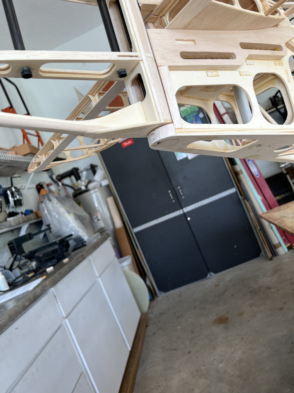
I decided to tackle fitting the tail feathers at this time. Let me say this up front: between the plans and parts supplied I could not figure out how to work out the mount tubes/bolt arrangement. The best way I could see to do it is the following.
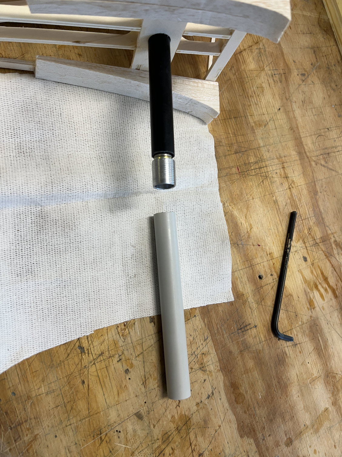
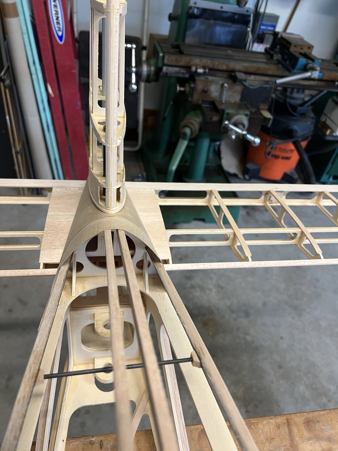
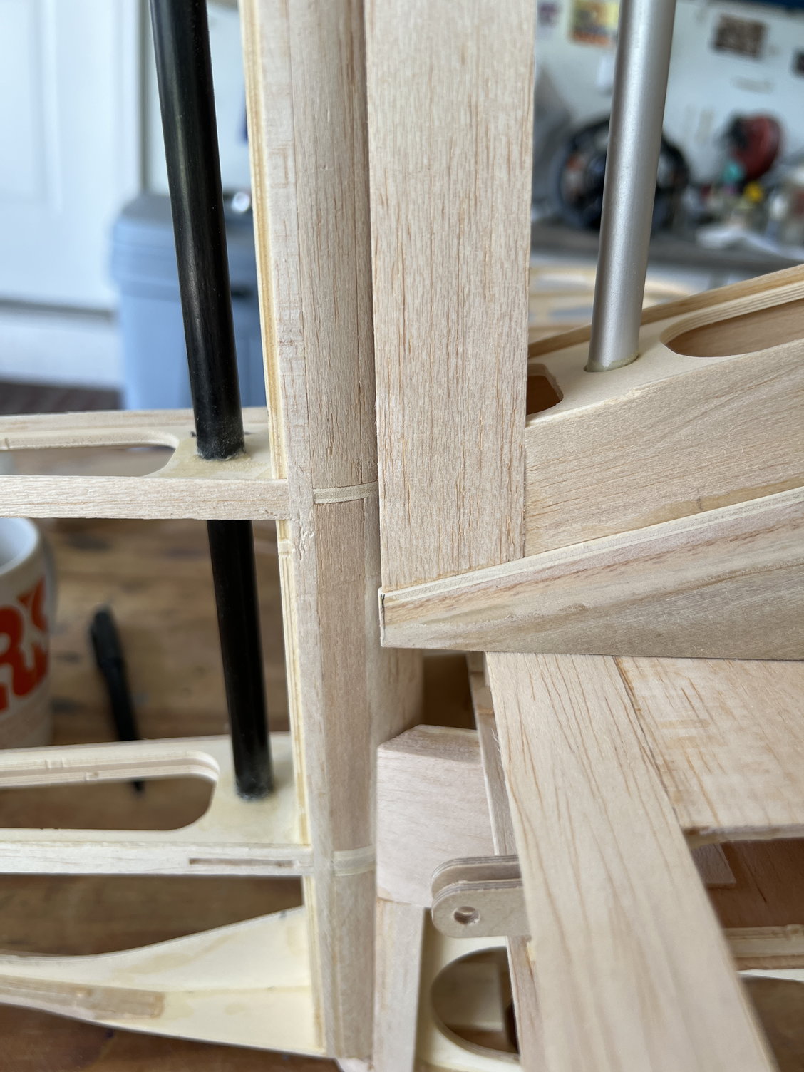
You will see that I machined a mounting shell that I mounted in the receptacle tube in the fuselage (with structural epoxy - hysol). The carbon tube in the vertical stabilizer has the supplied threaded insert glued into it.
The carbon stab tube only goes int the receptacle tube about 1/4” so after installation I wrapped the top of it with carbo tow to keep it from splitting out.
Undoubtedly there are other ways to do this but when all is said and done I’m very happy with how this turned out.
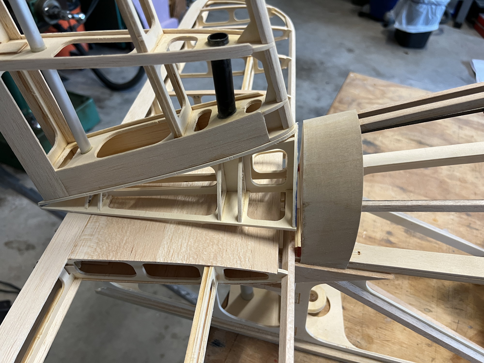
So this is the way the kit naturally fits together. I was a little surprised. I just assumed the front of the fairing frame would fit against the fuselage. Nope. Just so you’re not surprised when you get to this point.
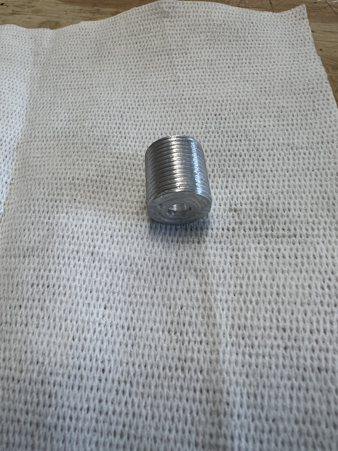
Shallow threads on the outside to hold the epoxy
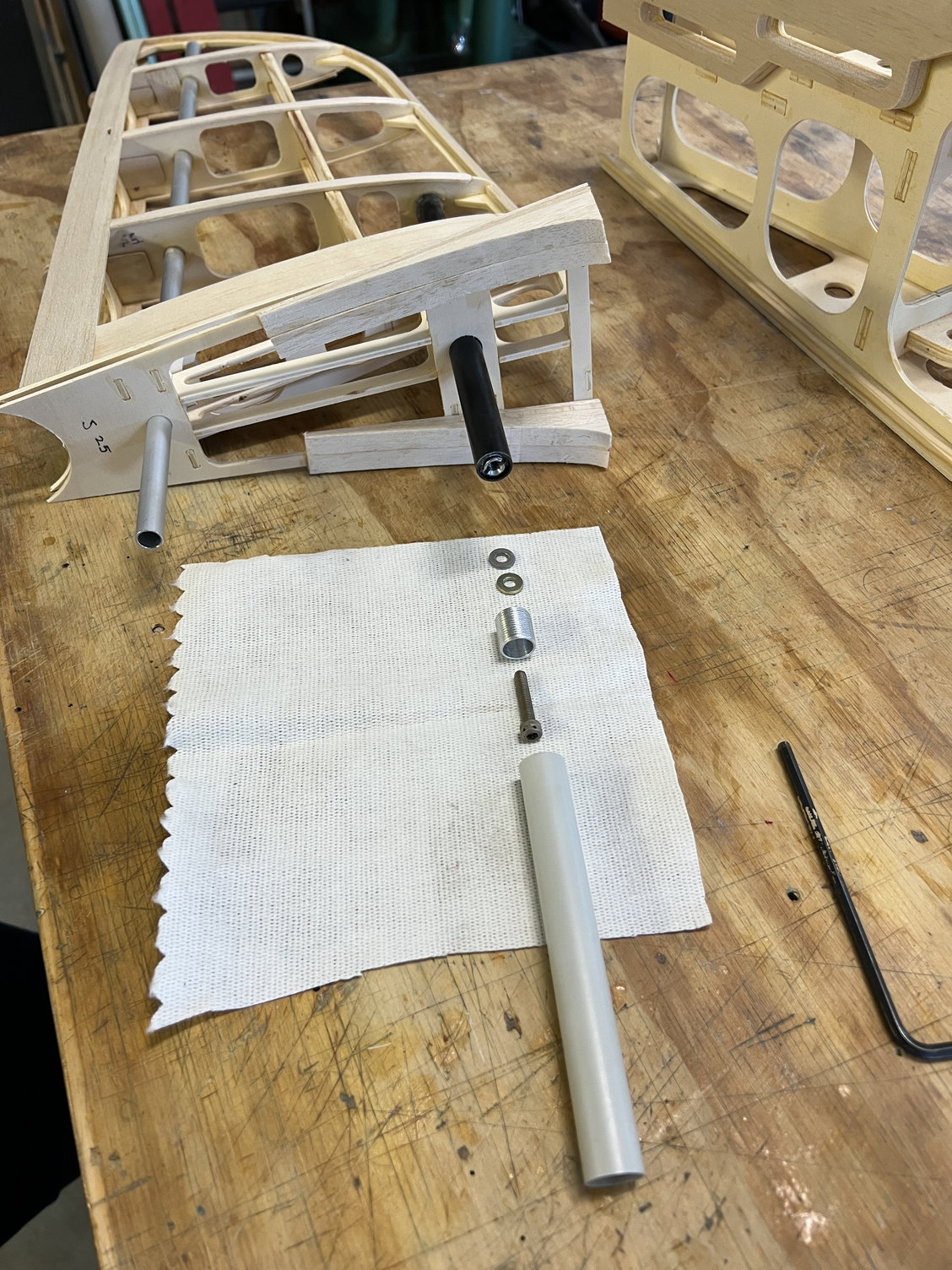
The two washers were just for adding a little extra room to work with after everything is glued up. They are NOT used in the final install.
You will see that I machined a mounting shell that I mounted in the receptacle tube in the fuselage (with structural epoxy - hysol). The carbon tube in the vertical stabilizer has the supplied threaded insert glued into it.
The carbon stab tube only goes int the receptacle tube about 1/4” so after installation I wrapped the top of it with carbo tow to keep it from splitting out.
Undoubtedly there are other ways to do this but when all is said and done I’m very happy with how this turned out.
So this is the way the kit naturally fits together. I was a little surprised. I just assumed the front of the fairing frame would fit against the fuselage. Nope. Just so you’re not surprised when you get to this point.
Shallow threads on the outside to hold the epoxy
The two washers were just for adding a little extra room to work with after everything is glued up. They are NOT used in the final install.
Last edited by mitchilito; 05-10-2022 at 05:02 AM.
The following users liked this post:
Steve (05-12-2022)

The following users liked this post:
mitchilito (05-14-2022)
05-14-2022, 11:06 AM
#43
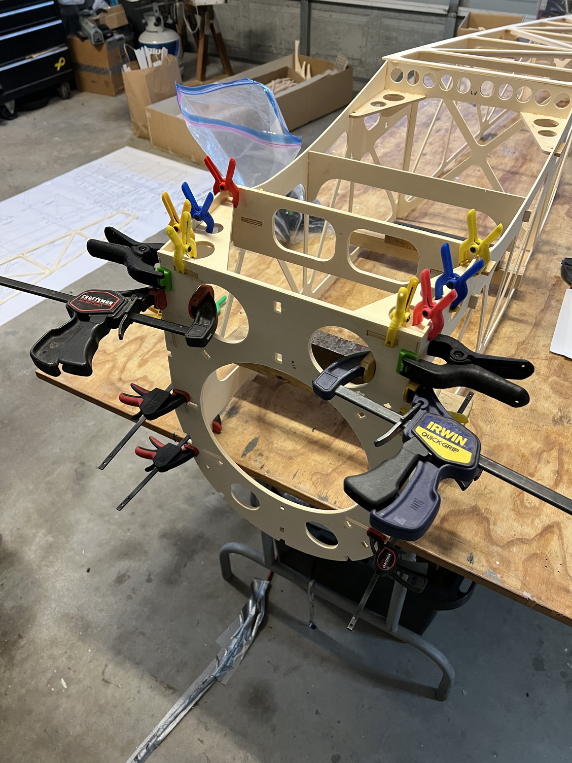
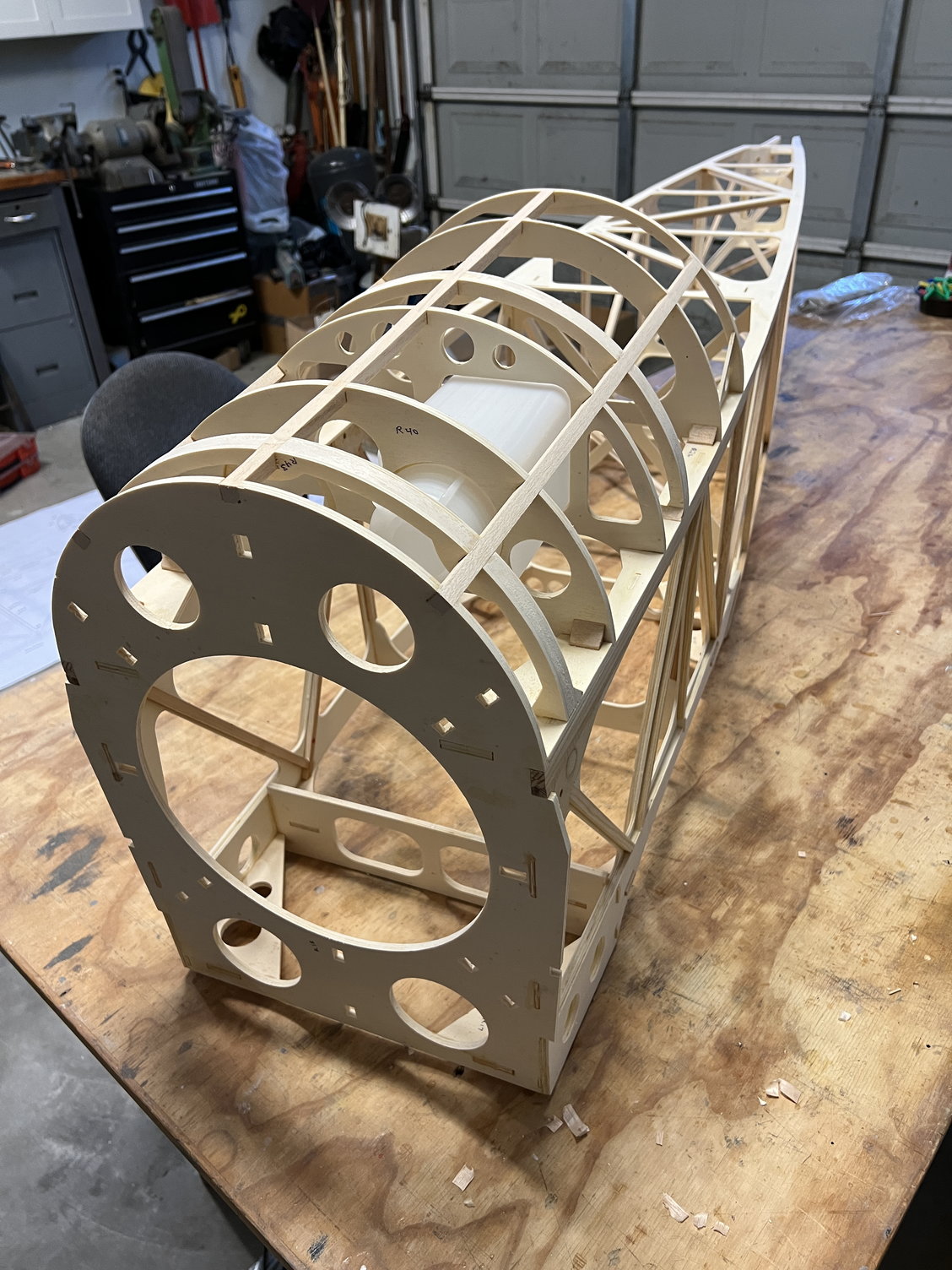
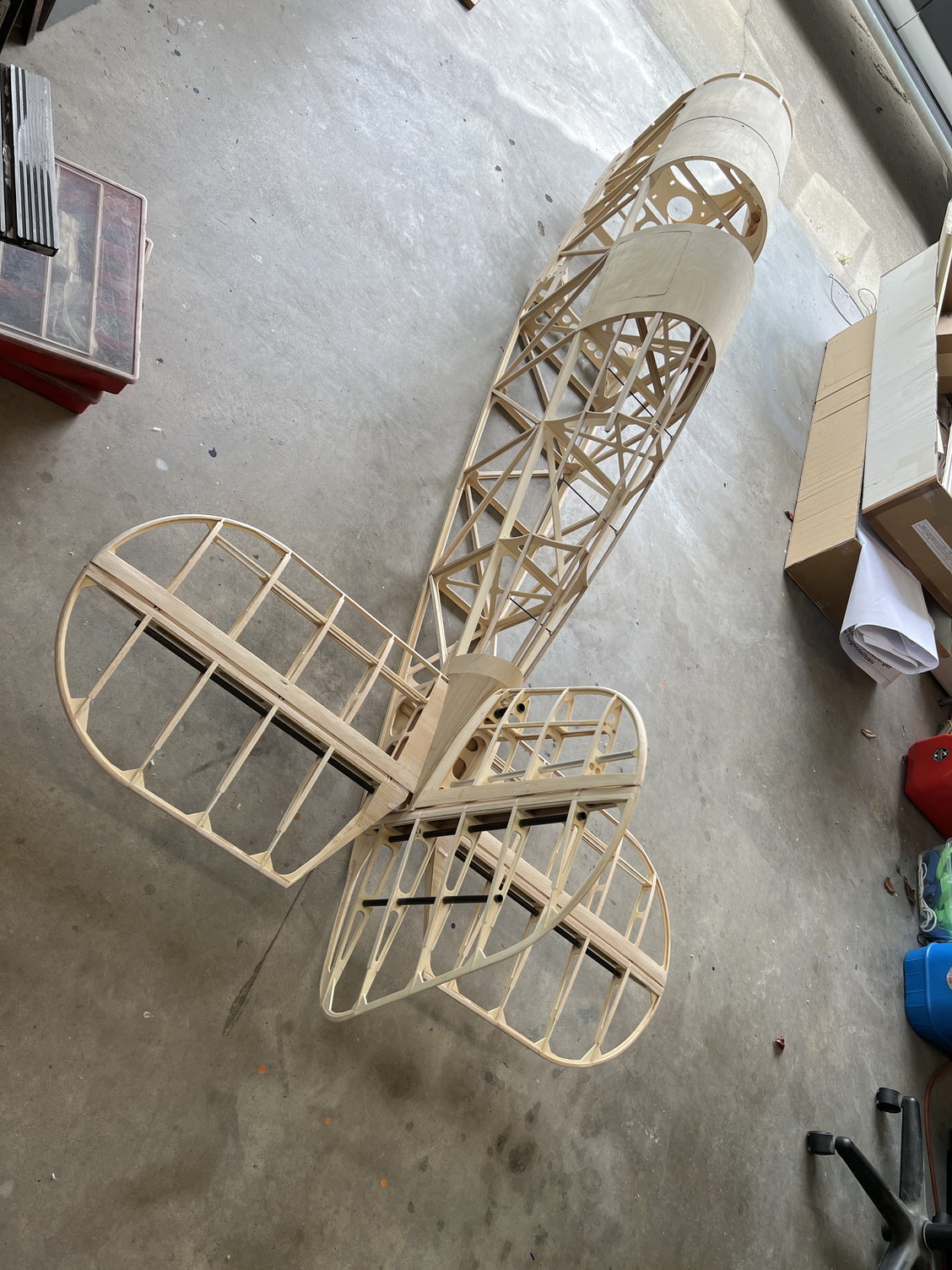
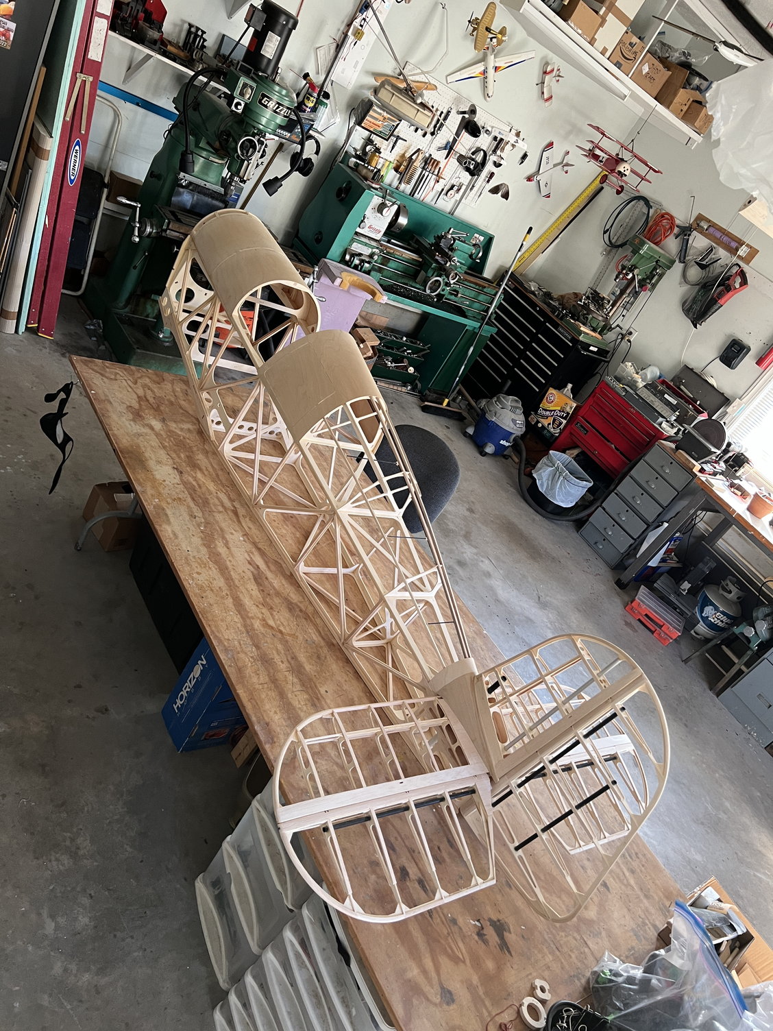
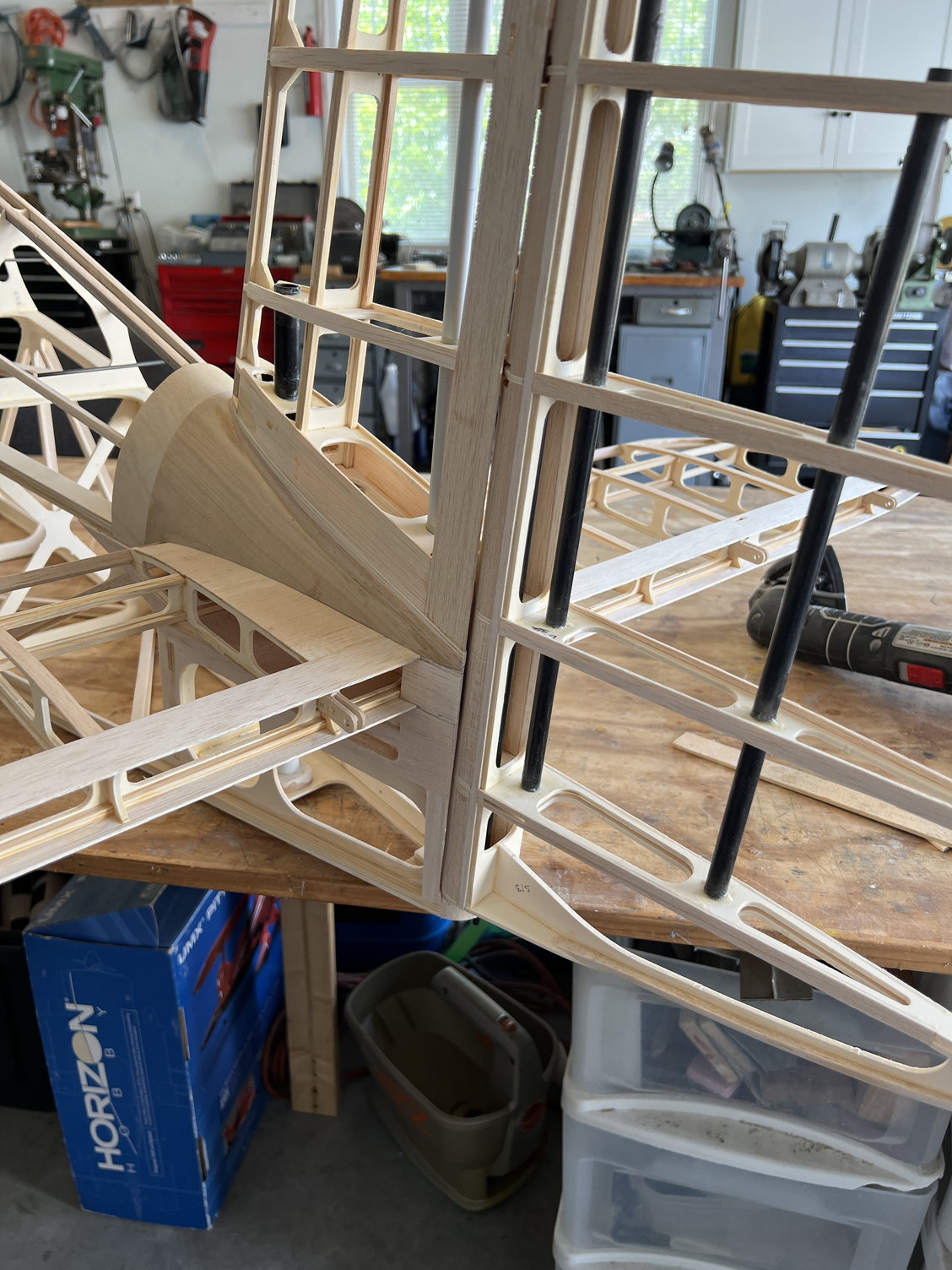
And now for the fun part: getting it all to fit together.. . .
I was concerned that there was a big gap between the fuselage bulkhead and the tail fairing assembly. But soon enough I saw it's NOT an issue. Sheeting the fairing is pretty straightforward and that's the first thing to do.
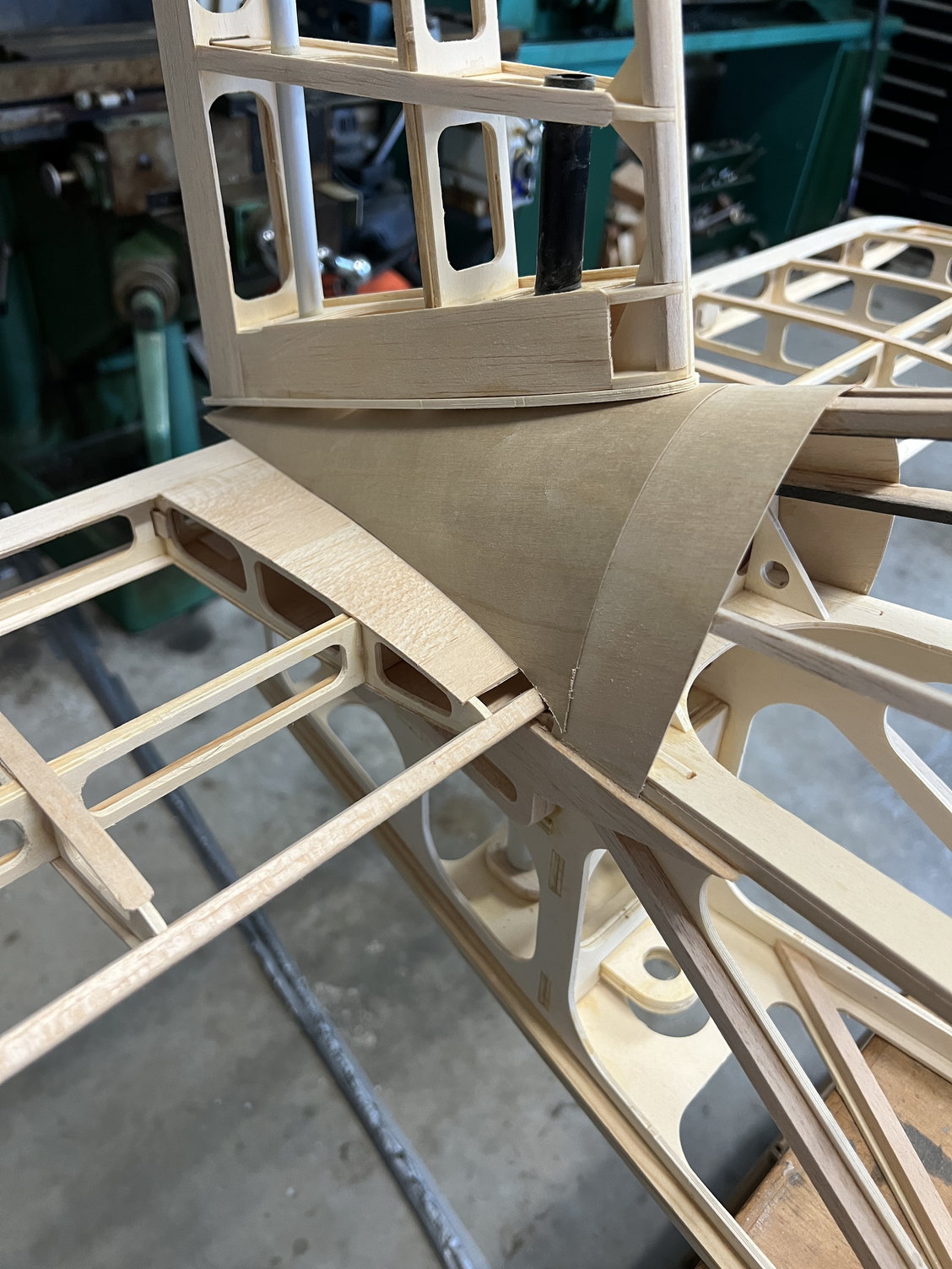
I was concerned that there was a big gap between the fuselage bulkhead and the tail fairing assembly. But soon enough I saw it's NOT an issue. Sheeting the fairing is pretty straightforward and that's the first thing to do.
05-14-2022, 11:14 AM
#44
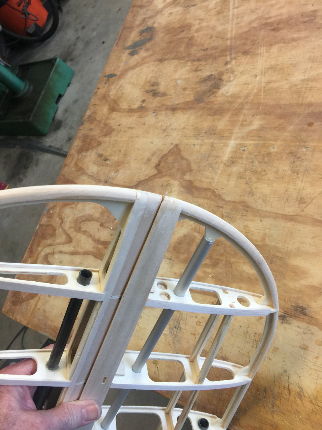
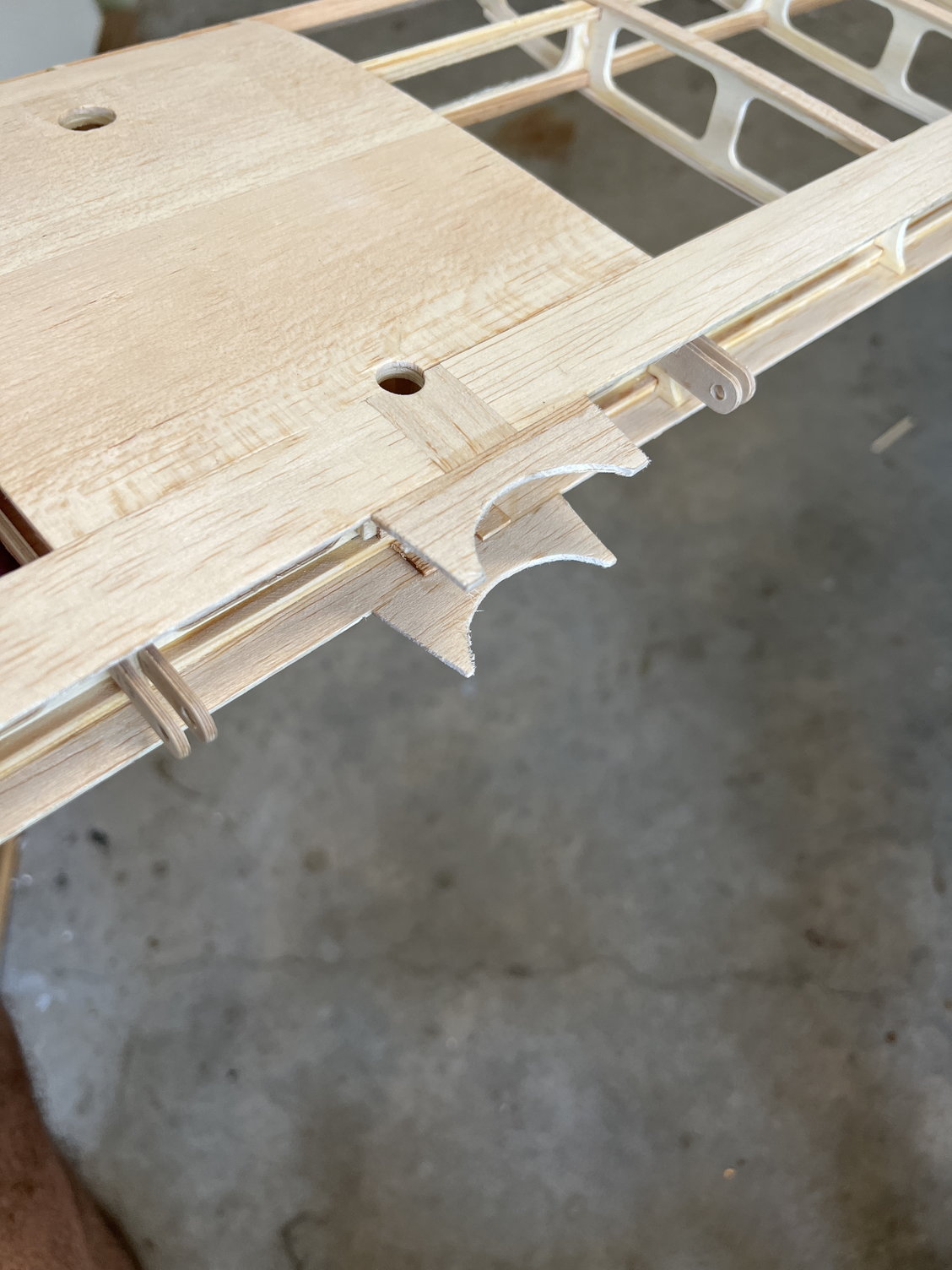
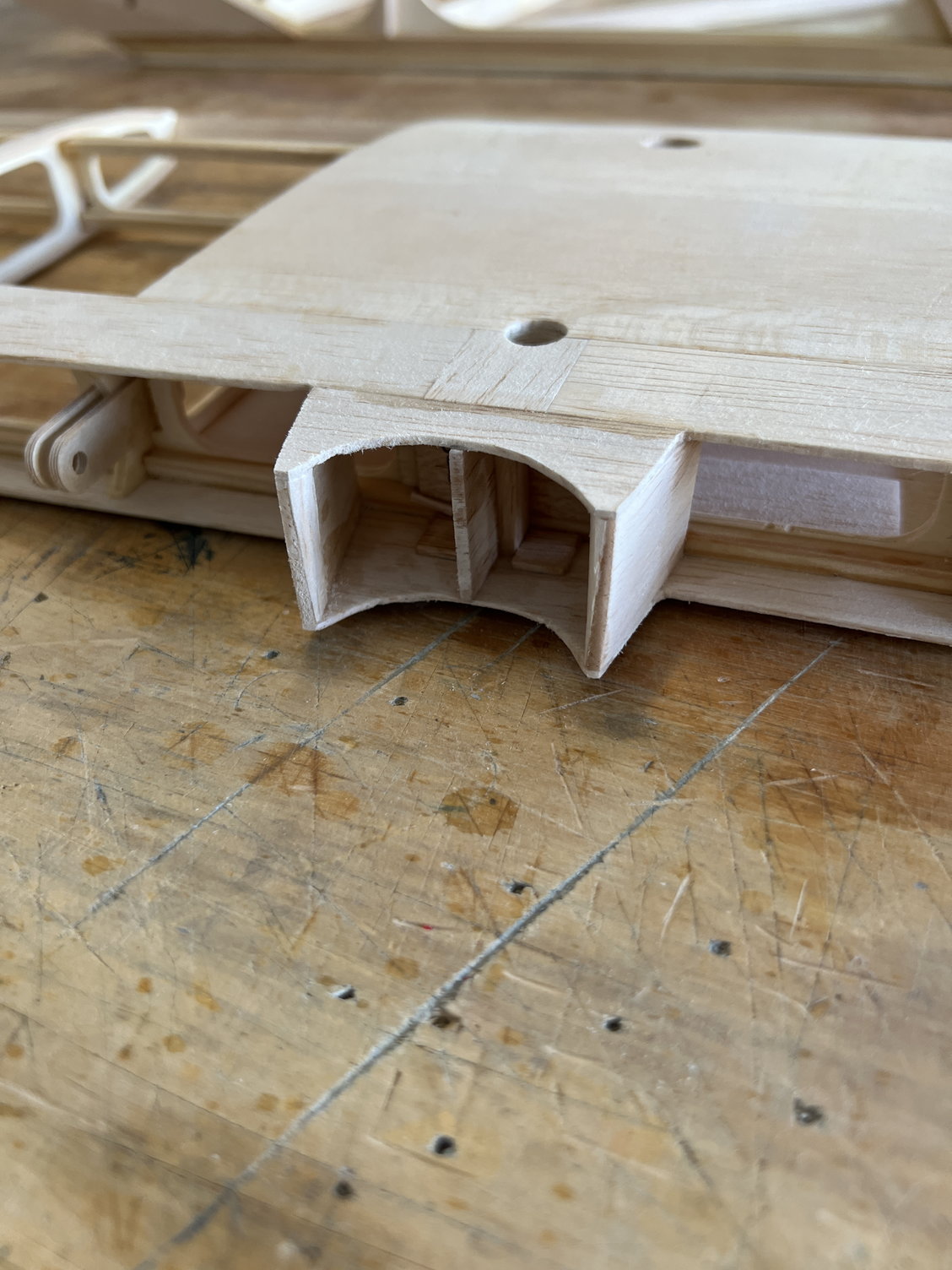
I was at a loss as to how to fill the gap between the vertical stab and the tail fairing so this is what I did. As you'll see I glued shaped balsa wedges to the bottom of the fairing former S20. Then I wrapped the top of the fairing with 120 grit sandpaper and used it to sand the S20 assembly to a perfect fit. I know "pride goeth before the fall" but I am blown away by how good I got it all to fit together. I had my doubts!
I got the pictures out of order. The bottom picture is the start of the wedges that get glued to S20
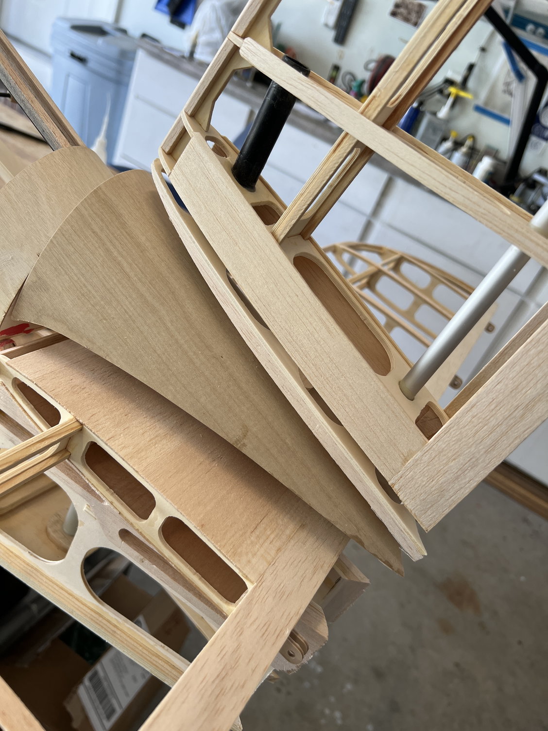
Here's all the pieces that have to fit together
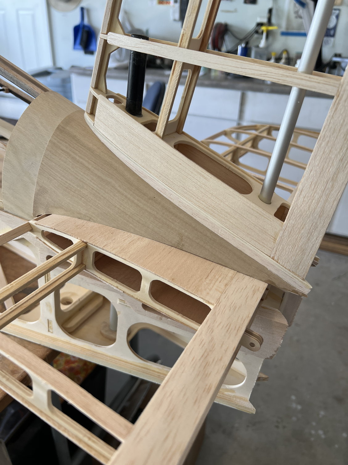
Look closely. I nailed the fit!
I got the pictures out of order. The bottom picture is the start of the wedges that get glued to S20
Here's all the pieces that have to fit together
Look closely. I nailed the fit!
Last edited by mitchilito; 05-14-2022 at 03:10 PM.
The following users liked this post:
Steve (05-14-2022)
The following users liked this post:
Steve (05-14-2022)
05-16-2022, 06:36 AM
#46
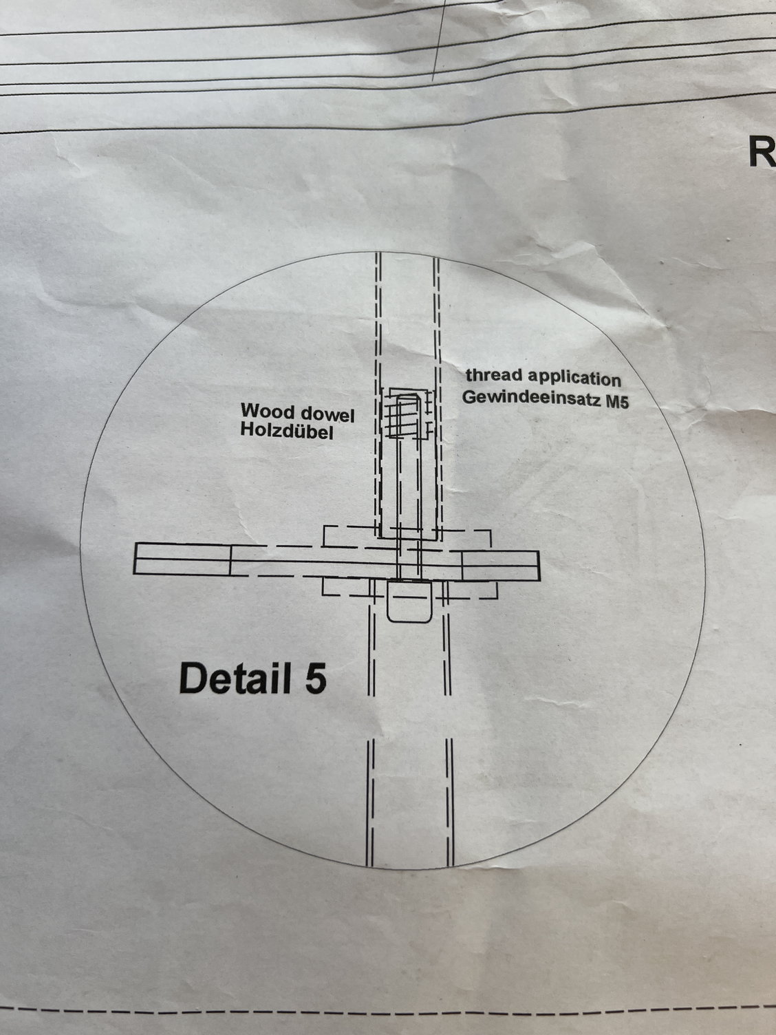
Let’s step back in time a few days to when I was installing R20A and B which has the receptacle for the vertical stabilizer in it.
I said I couldn’t figure out how they intended this all to go together but while I was looking at the plans today for others things I noticed “detail 5” hee hee hee.
Never noticed it when I needed it. To be honest I like my method better: it allows the tubes to overlap more. But it does require some machining.
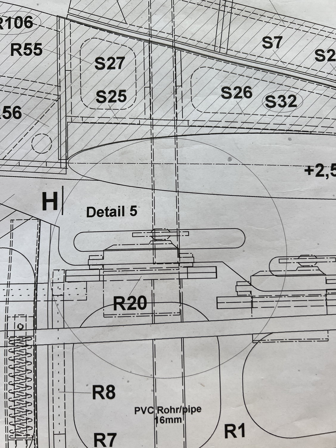
Can’t believe I missed this entirely!
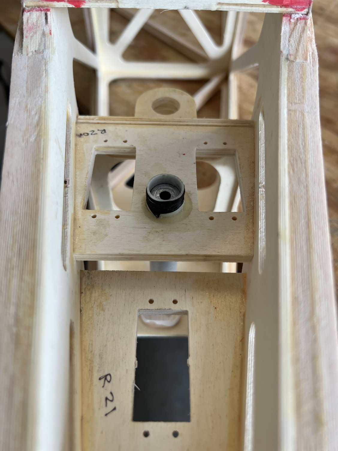
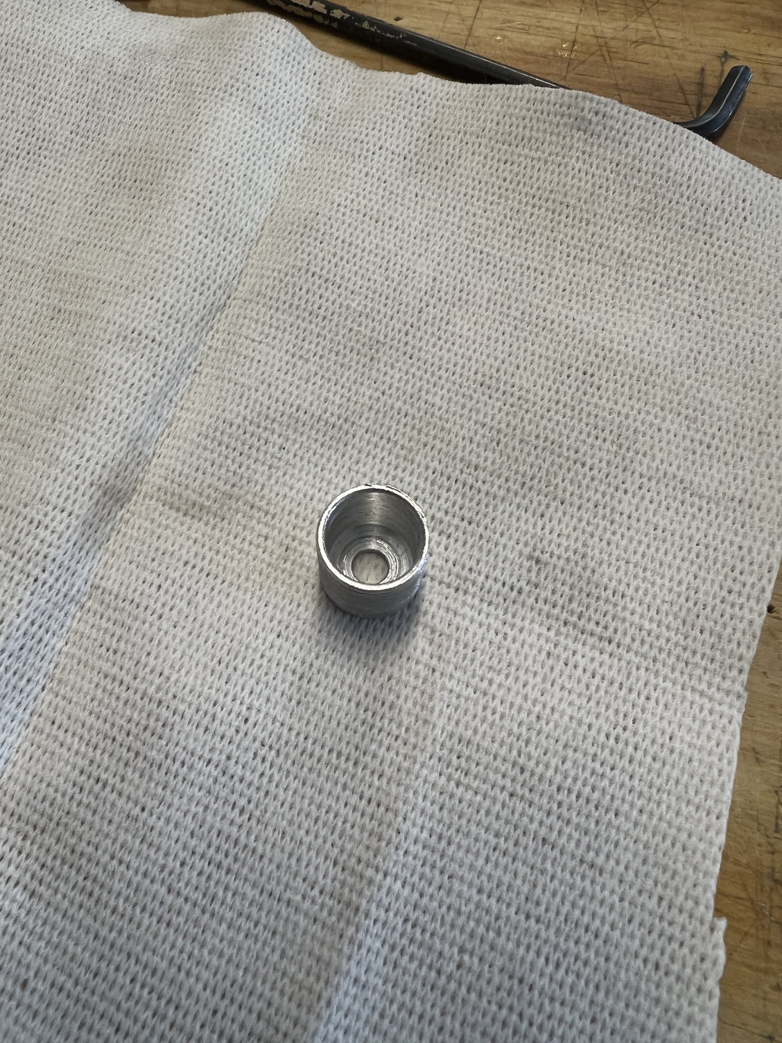
This is looking down at my stab receptacle. You can see my aluminum plug in there and also how I wrapped the top of it with carbon tow. Very strong and light.
I said I couldn’t figure out how they intended this all to go together but while I was looking at the plans today for others things I noticed “detail 5” hee hee hee.
Never noticed it when I needed it. To be honest I like my method better: it allows the tubes to overlap more. But it does require some machining.
Can’t believe I missed this entirely!
This is looking down at my stab receptacle. You can see my aluminum plug in there and also how I wrapped the top of it with carbon tow. Very strong and light.
Last edited by mitchilito; 05-16-2022 at 06:39 AM.
The following users liked this post:
Steve (05-16-2022)
05-19-2022, 03:06 PM
#47
Time to tackle the back end of the fuselage. The plans/instructions don't really cover this aspect of the build so as with many other parts of this build, I just winged it! See captioned pictures for explanation.
I started by adding balsa pieces to the rear outsides of the fuselage. then you'll see I installed the bottom hinge bracket on a balsa wedge.
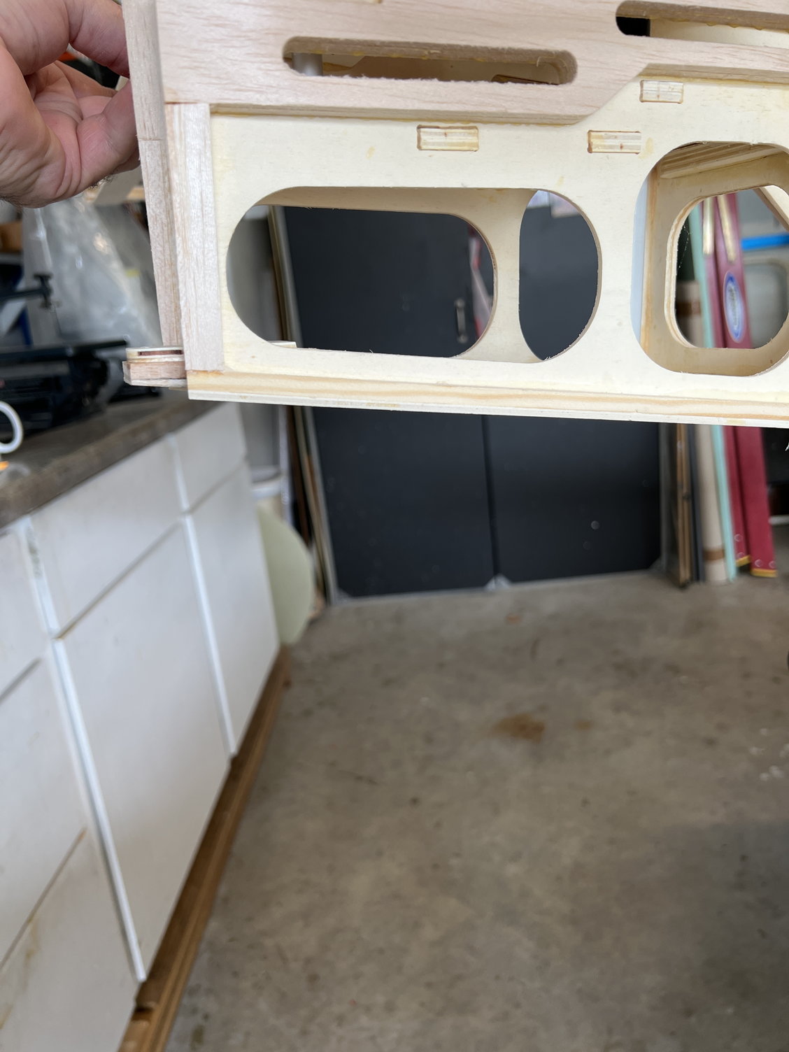
Wedge is required to level the hinge to fuselage centerline.
Lake MANY parts of this kit, a bunch of little balsa pieces are scabbed in to finish things off.
Here's how it turned out. I'm very very happy.
I started by adding balsa pieces to the rear outsides of the fuselage. then you'll see I installed the bottom hinge bracket on a balsa wedge.
Wedge is required to level the hinge to fuselage centerline.
Lake MANY parts of this kit, a bunch of little balsa pieces are scabbed in to finish things off.
Here's how it turned out. I'm very very happy.
Last edited by mitchilito; 05-20-2022 at 03:39 AM.
05-19-2022, 03:16 PM
#48
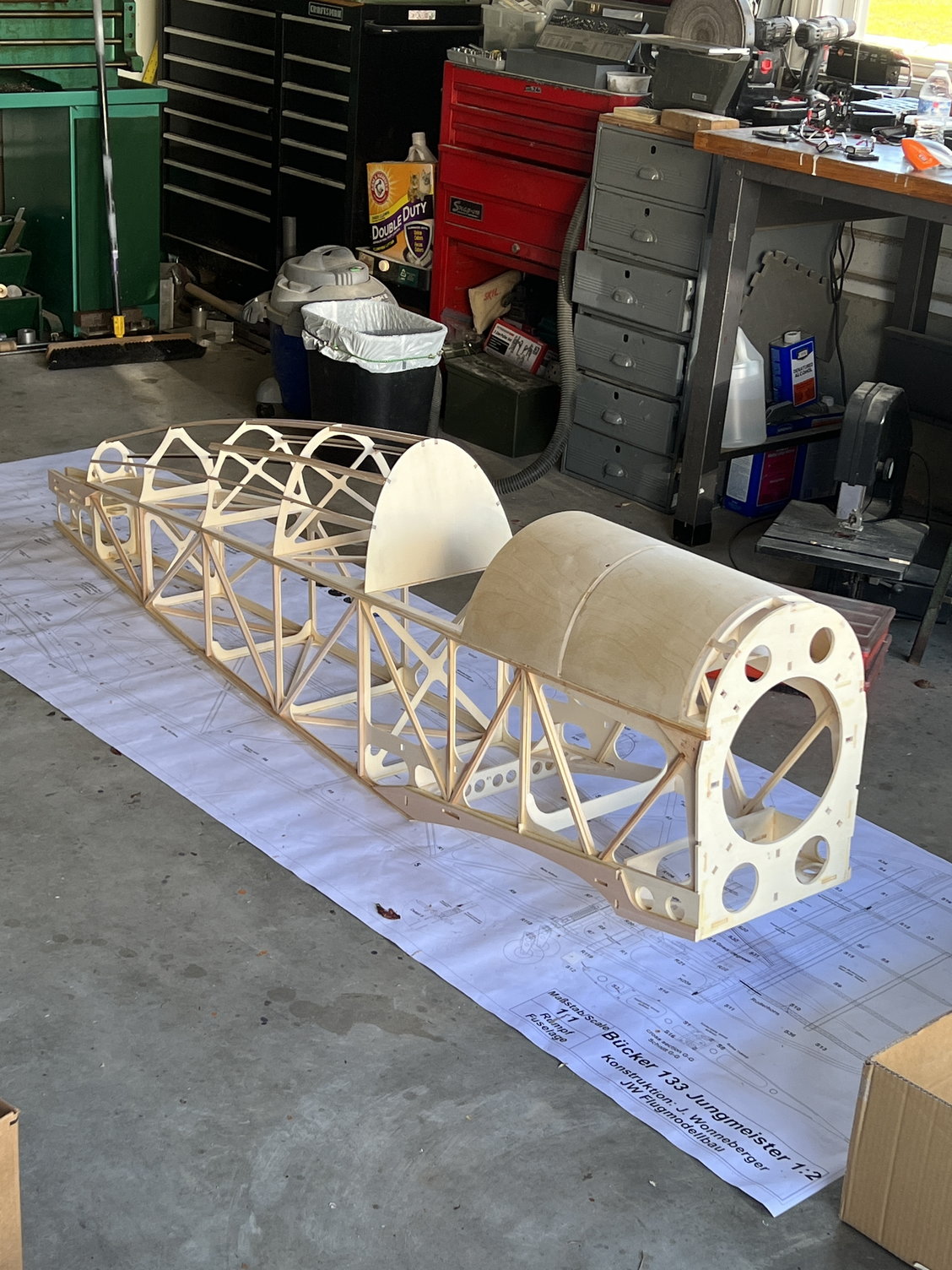
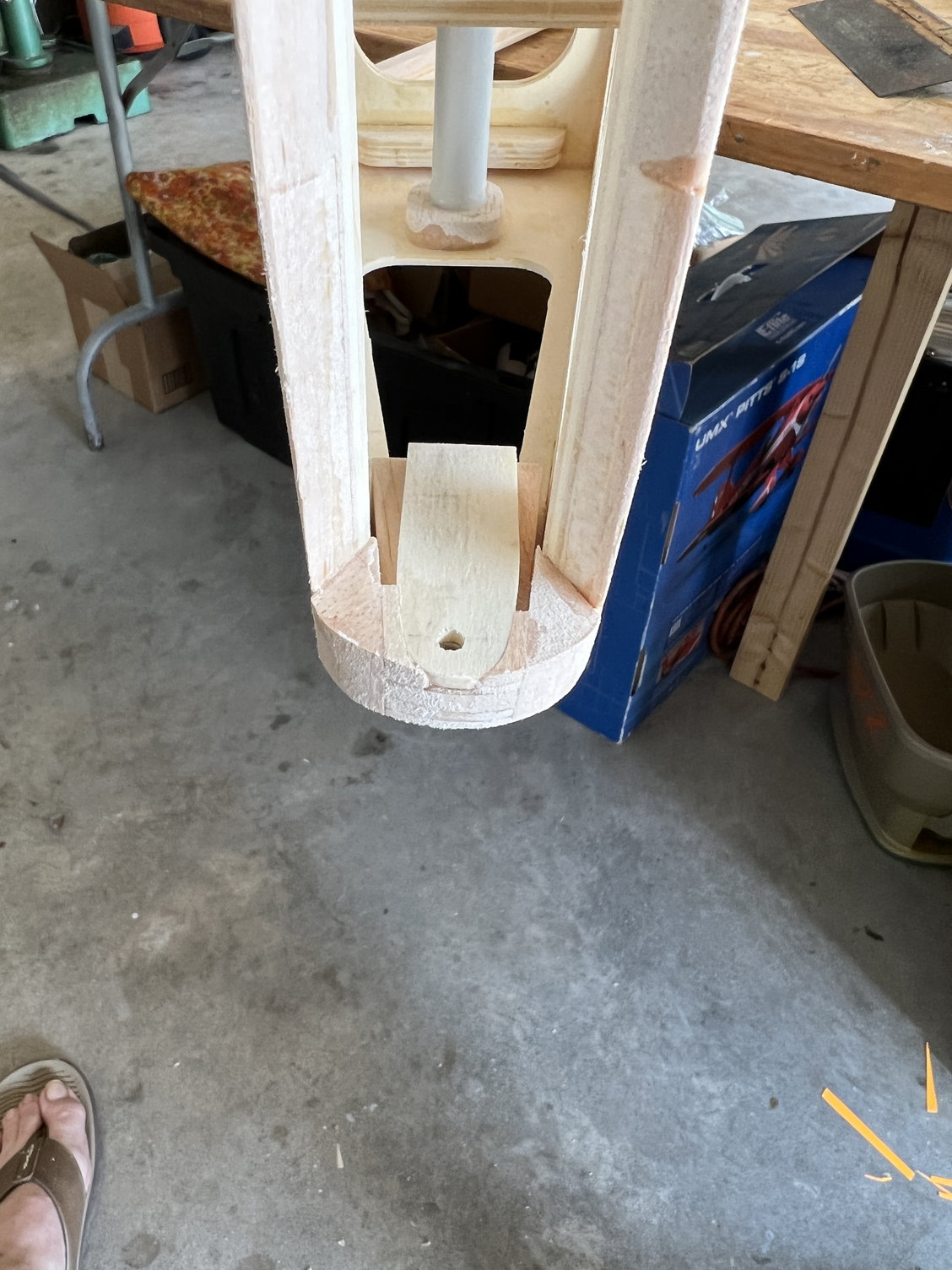
Once I had the rudder mounted and faired in nicely I had to tackle the big empty space behind the stabilizer. I've notice several JW Bucker's that have this gap and I didn't like the look of it at all.
Here's what it looks like unfinished.
This is how I started.
This is the final fairing
Looks and works fantastically
Here's what it looks like unfinished.
This is how I started.
This is the final fairing
Looks and works fantastically
Last edited by mitchilito; 05-19-2022 at 03:20 PM.
The following users liked this post:
Steve (05-19-2022)
