


Giant Astro Hog Laser Cut Kit - Jerry Bates
 11-17-2020, 07:55 PM
#101

Thread Starter
I must have had a few minutes to many, and I decided to look into the engine choice again.
The engine on the plans is a Quadra Q-35 "with overbalanced flywheel" and there is additional comment "18x10 Zinger cut to 17x10"...
The most powerful model of the Q-35 produced 1.9Kw @ 8,500RPM which is 2.13Nm (Max static RPM) and 1.9Kw @ 11,000RPM which is 1.65Nm (Max flying RPM). It produce 2.6BHP. The Q-35 weight is 1,800g without muffler. As to prop recommendations, the manual states "Diameter:18-20, Pitch: 8-12"
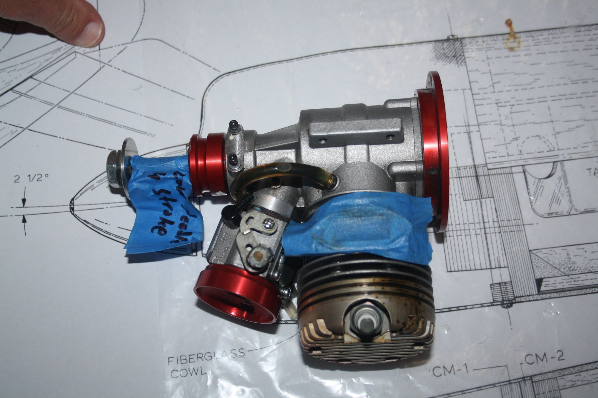
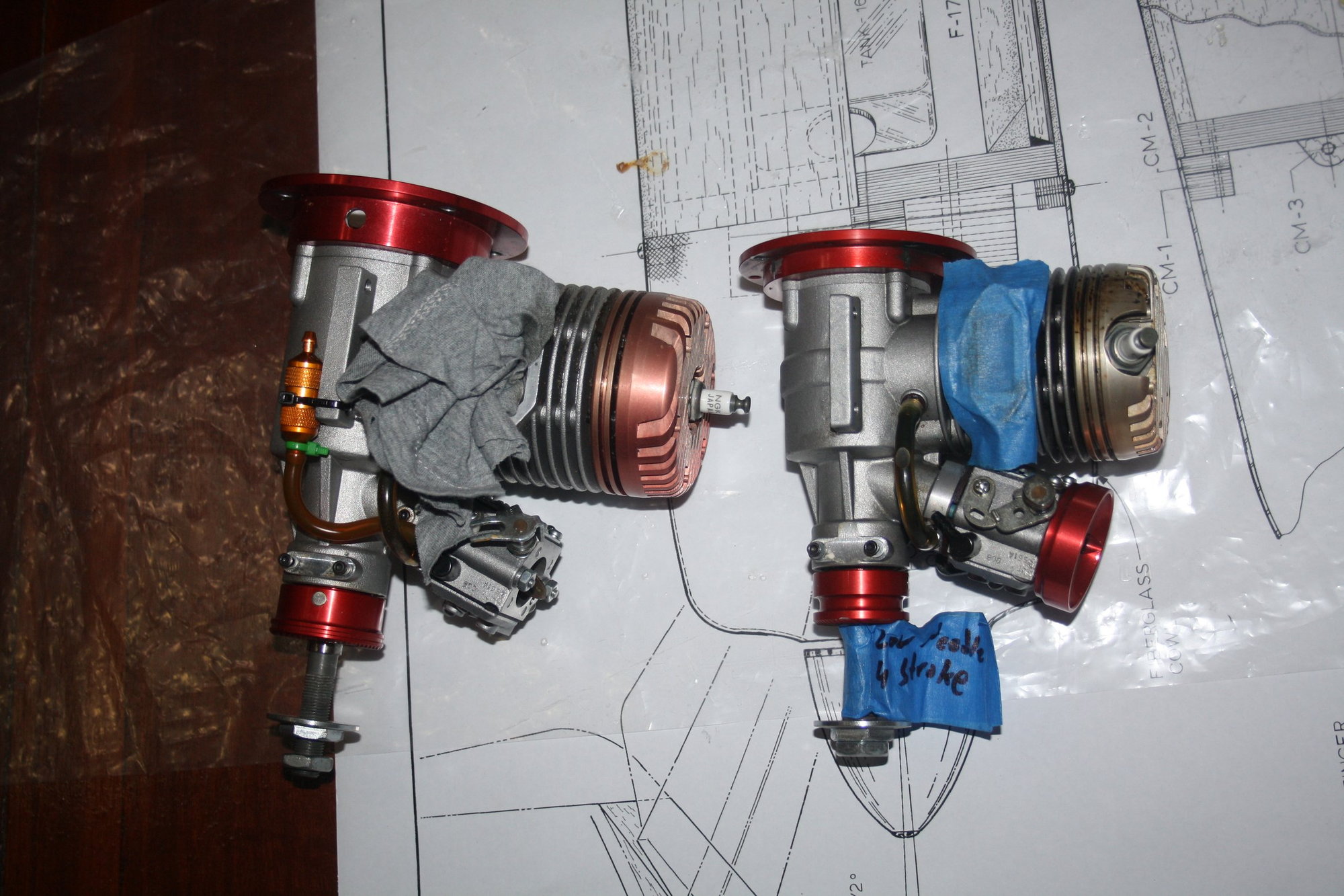
In comparison, the three engines I currently have on the shelf:
The MVVS 30cc has advertised maximum power output of 4.1 HP @ 9000 RPM, which is 3.01Kw... It has maximum torque of 3.5 Nm @ 8000 RPM (RPM range is 1,400 – 9,500), Total weight including ignition of ~1,130g and I use it with a 18x8 prop.
The DLE 35RA has advertised maximum power output of 4.1 HP @ 8,500 RPM, which is 3.01Kw, total weight of 1,248g including everything (Ignition + Muffler + Standoffs) and I usually use 19x8 prop on it.
I could not find power output figures for the MVVS 40cc IFS in the manual or online, but from experience it is higher than the DLE 35RA. It weight 1,647g including ignition, has RPR range of 1,400 - 9,000RPM usually swinging a 20x8 prop...
As can be seen, even the MVVS 30cc is more powerful than the Q-35 by some margin while being much lighter. This is what actually worries me. If I will need to add 800-1,000g of weight to the front I better go ahead with the MVVS 40cc and have insane amount of power.
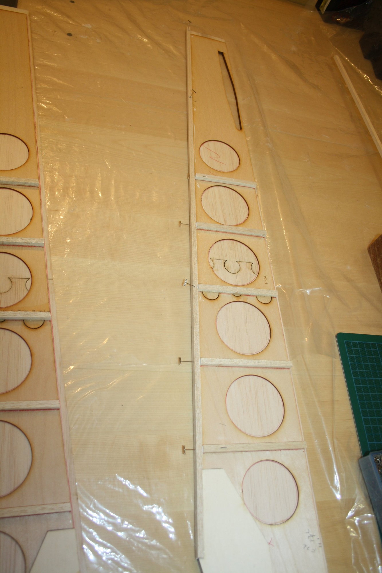
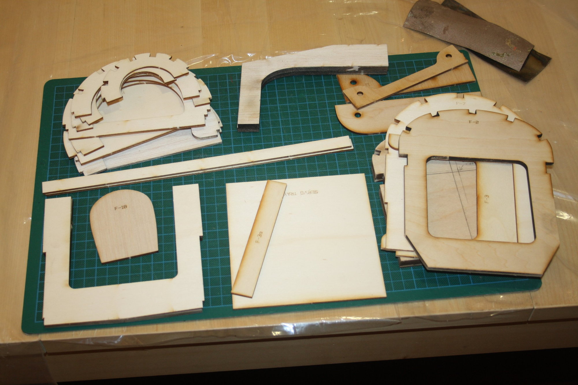
As to progress, I glued the bottom 1/4"SQ balsa strips and cut out the rest of the fuselage laser cut parts from the sheets and cleaned them up. While doing so I found that F7 was incorrectly cut.
Cheers,
Eran
The engine on the plans is a Quadra Q-35 "with overbalanced flywheel" and there is additional comment "18x10 Zinger cut to 17x10"...
The most powerful model of the Q-35 produced 1.9Kw @ 8,500RPM which is 2.13Nm (Max static RPM) and 1.9Kw @ 11,000RPM which is 1.65Nm (Max flying RPM). It produce 2.6BHP. The Q-35 weight is 1,800g without muffler. As to prop recommendations, the manual states "Diameter:18-20, Pitch: 8-12"
In comparison, the three engines I currently have on the shelf:
The MVVS 30cc has advertised maximum power output of 4.1 HP @ 9000 RPM, which is 3.01Kw... It has maximum torque of 3.5 Nm @ 8000 RPM (RPM range is 1,400 – 9,500), Total weight including ignition of ~1,130g and I use it with a 18x8 prop.
The DLE 35RA has advertised maximum power output of 4.1 HP @ 8,500 RPM, which is 3.01Kw, total weight of 1,248g including everything (Ignition + Muffler + Standoffs) and I usually use 19x8 prop on it.
I could not find power output figures for the MVVS 40cc IFS in the manual or online, but from experience it is higher than the DLE 35RA. It weight 1,647g including ignition, has RPR range of 1,400 - 9,000RPM usually swinging a 20x8 prop...
As can be seen, even the MVVS 30cc is more powerful than the Q-35 by some margin while being much lighter. This is what actually worries me. If I will need to add 800-1,000g of weight to the front I better go ahead with the MVVS 40cc and have insane amount of power.
As to progress, I glued the bottom 1/4"SQ balsa strips and cut out the rest of the fuselage laser cut parts from the sheets and cleaned them up. While doing so I found that F7 was incorrectly cut.
Cheers,
Eran
 11-17-2020, 09:10 PM
#102


Hi Eran,
look at this thread.
mikejwfly1 wrote that he used a Q42 but a Q52 or G62 would be much better. I think all of your 3 motors would do just fine. The question is which one would be the better one to do without lead
Manni
look at this thread.
mikejwfly1 wrote that he used a Q42 but a Q52 or G62 would be much better. I think all of your 3 motors would do just fine. The question is which one would be the better one to do without lead
Manni
Last edited by Nece; 11-17-2020 at 09:15 PM.
11-19-2020, 05:18 PM
#104
Thread Starter
Manni, Carl, thank you for the comments.
For reference, the U.S. Engines 41cc weight is 2,041g without muffler producing 3 BHP. This and the comment on Manni's linked thread lead me to select the MVVS 40cc for this build.
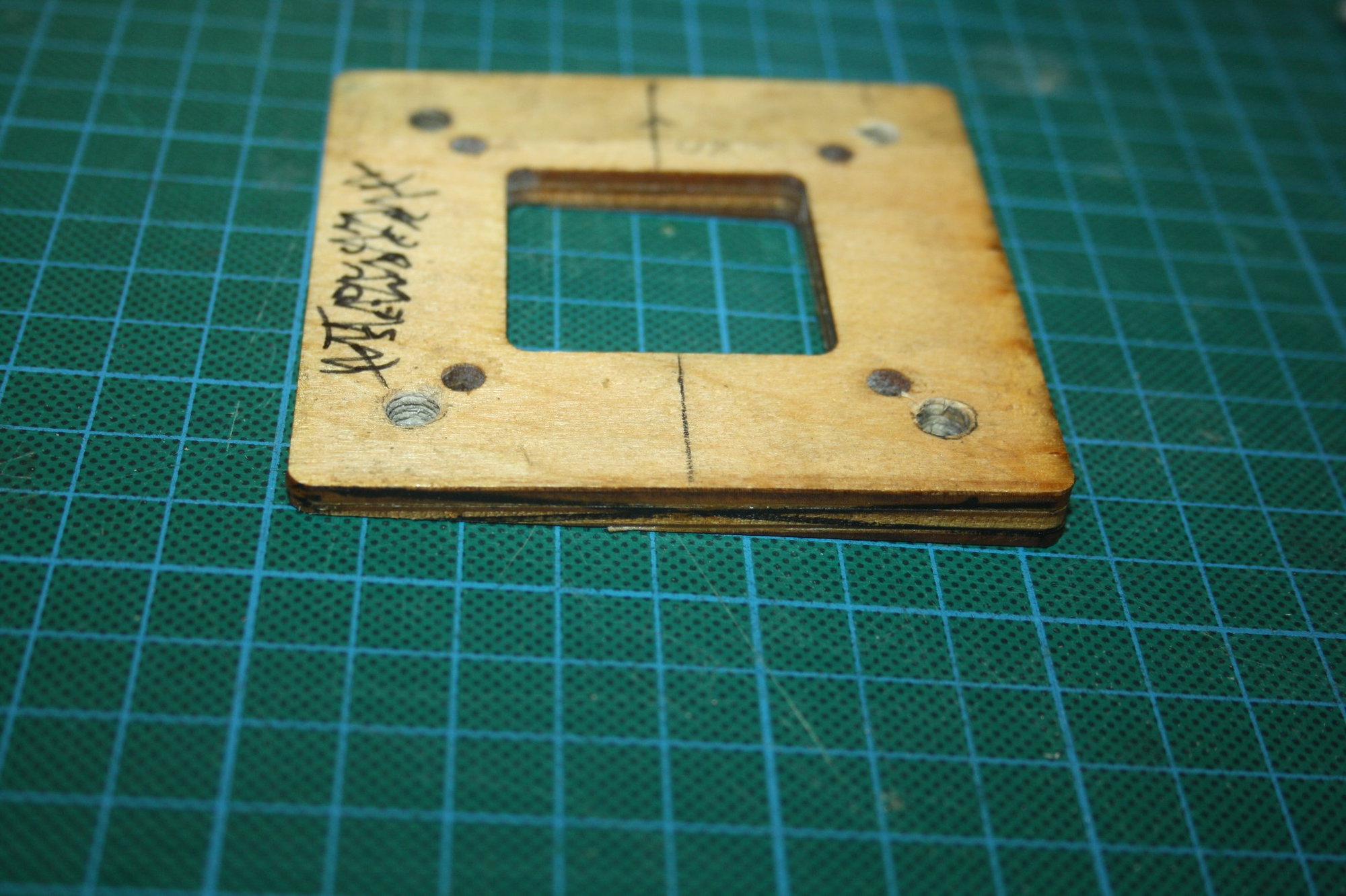
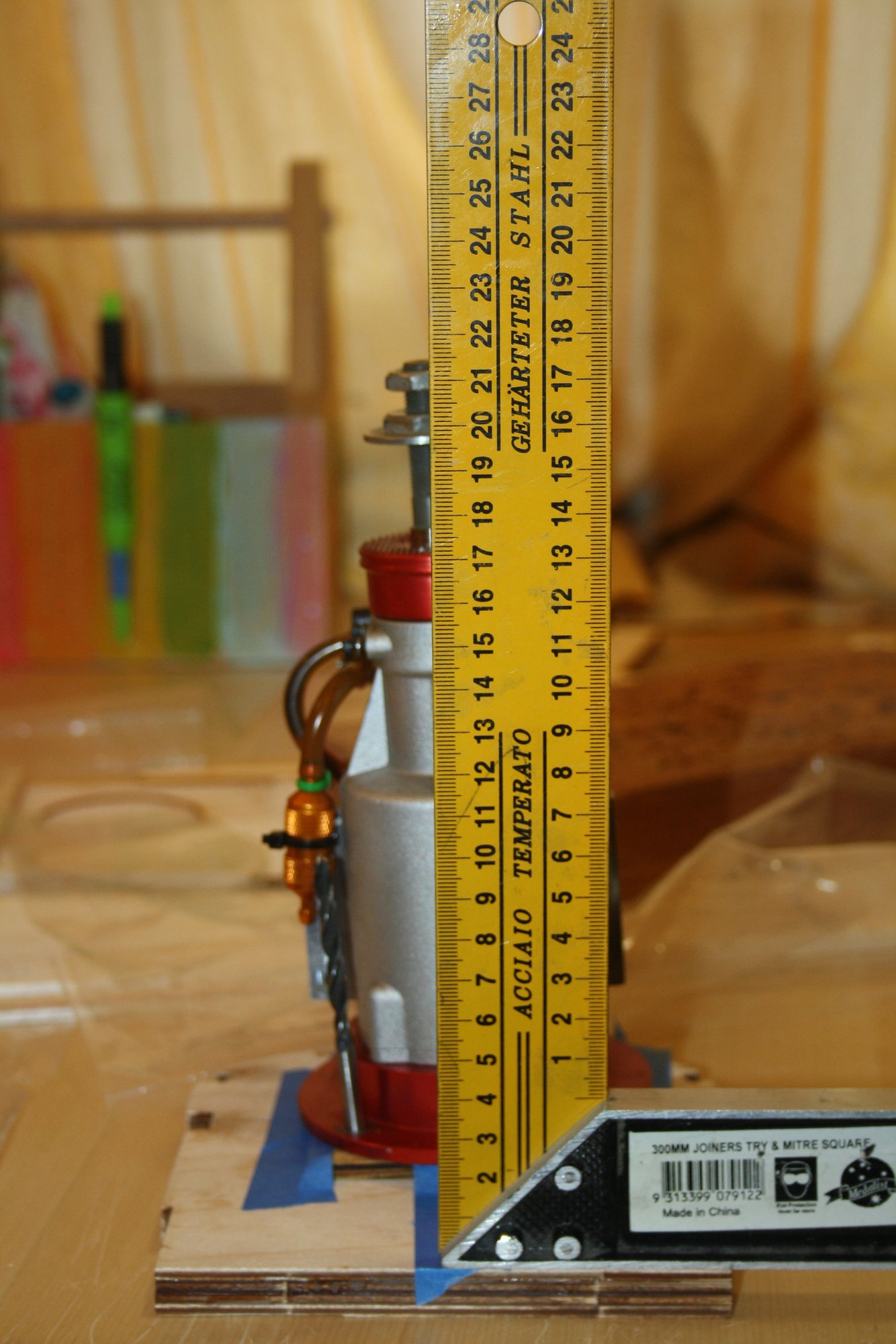
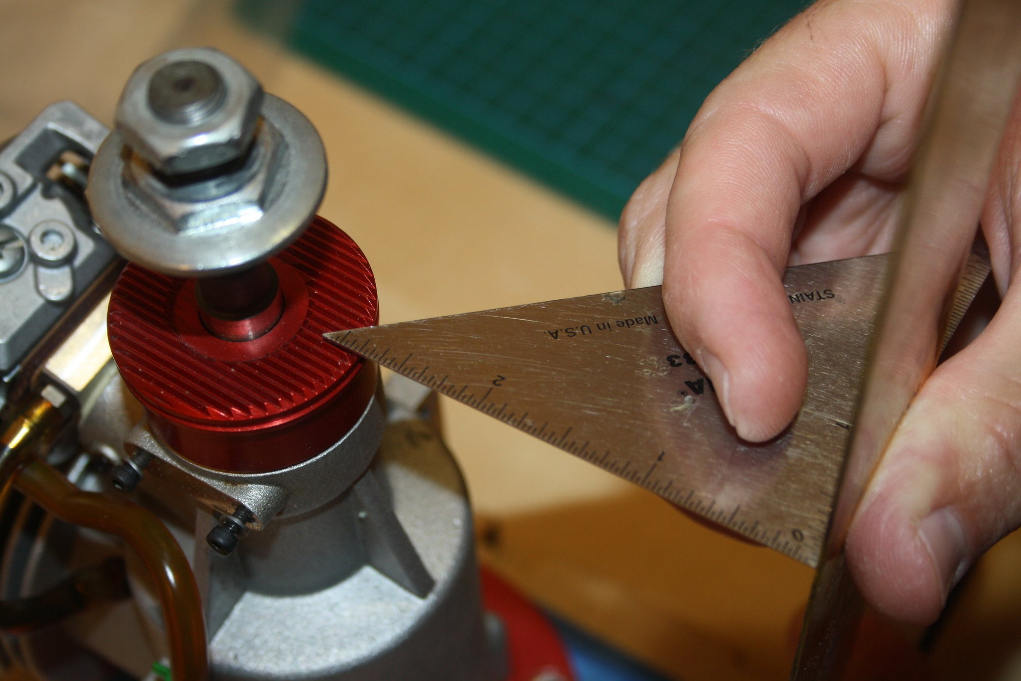
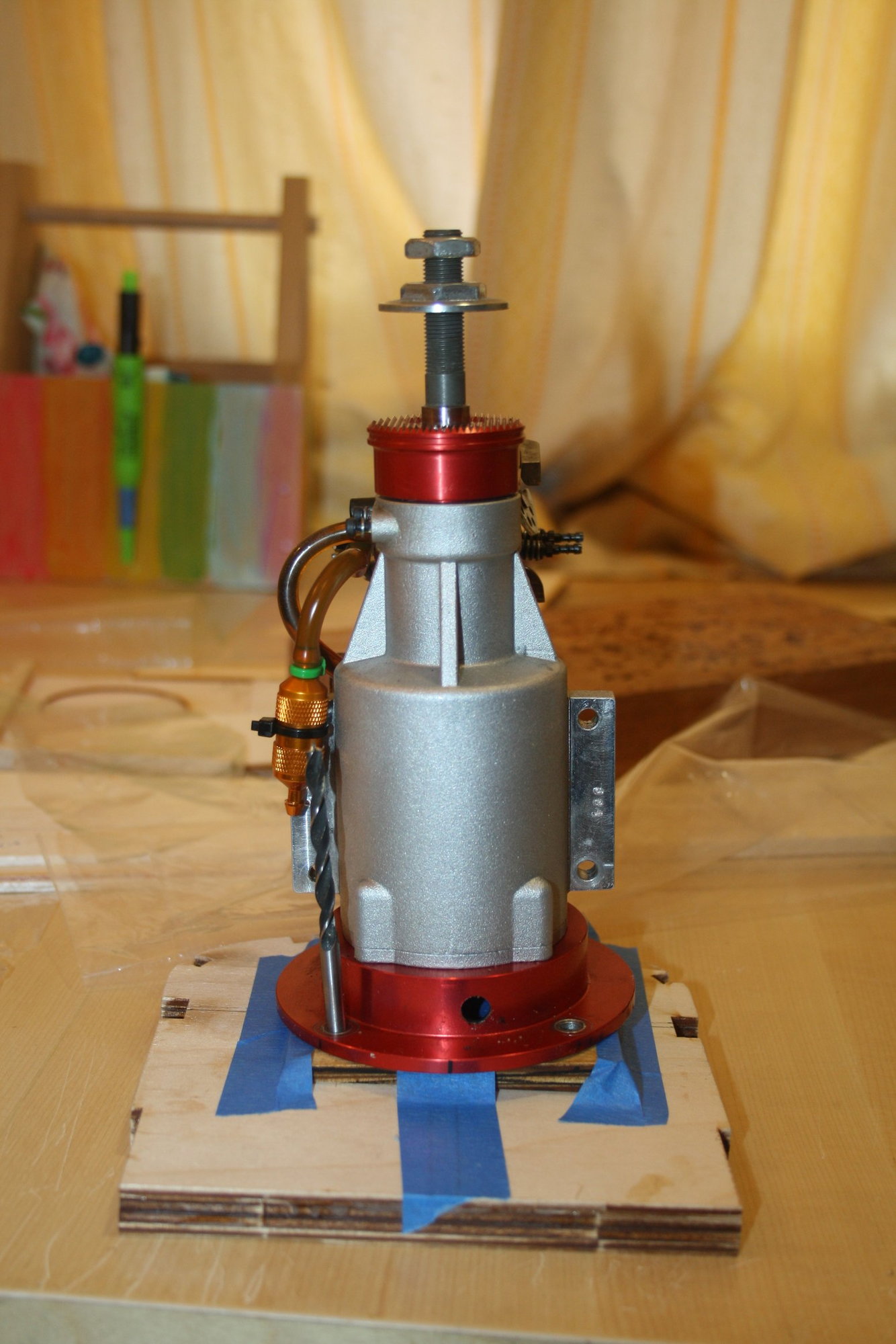
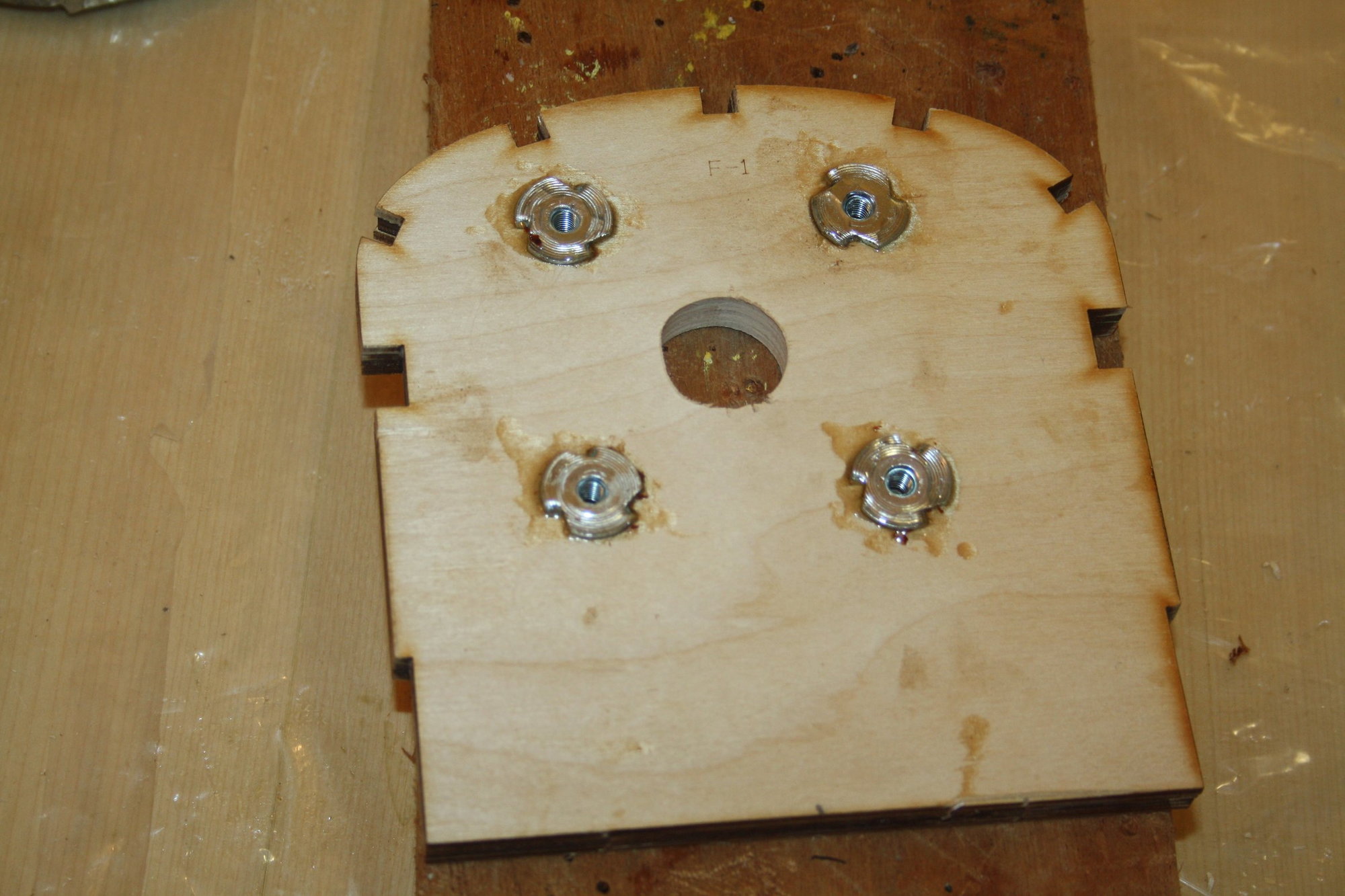
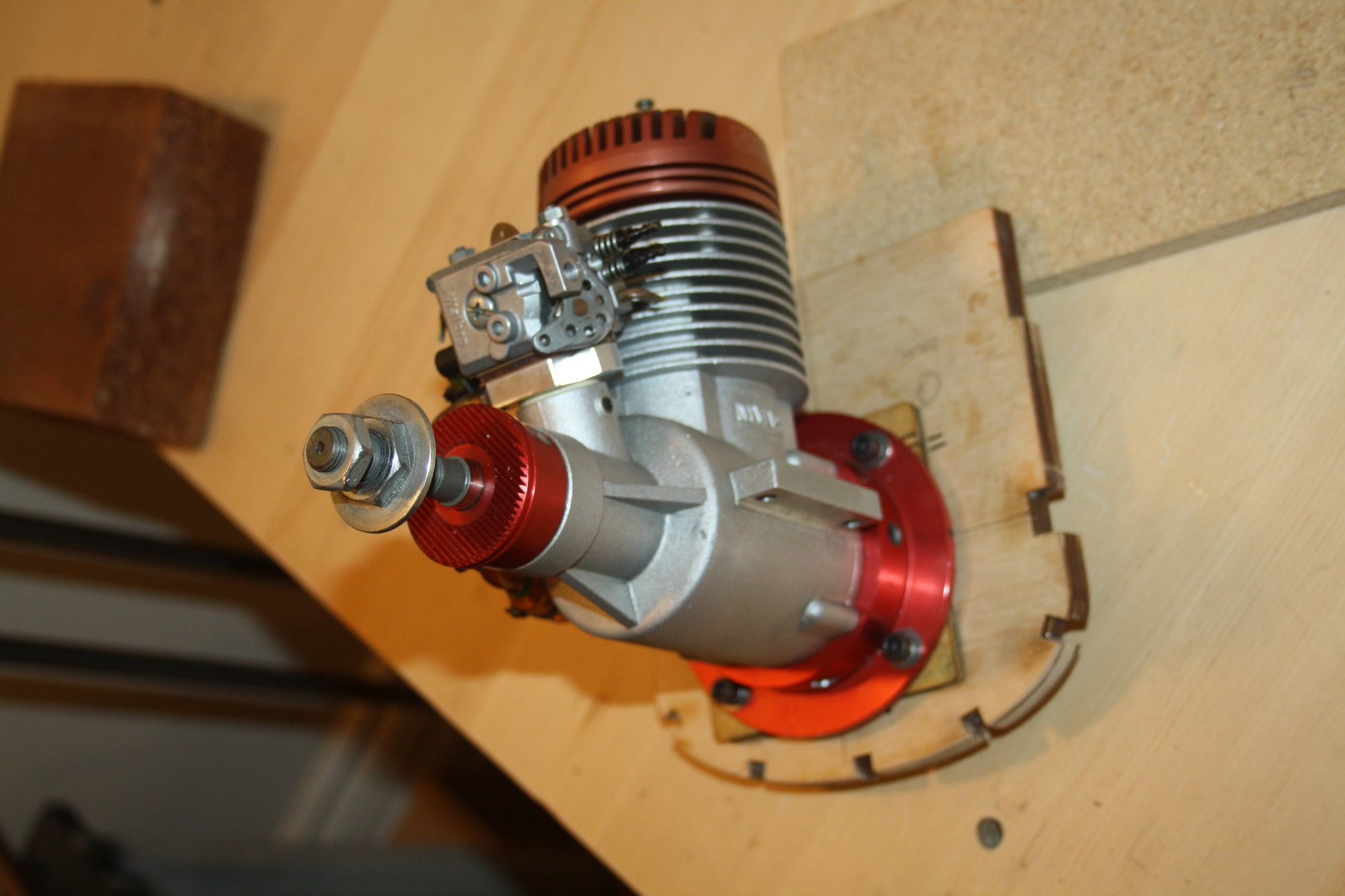
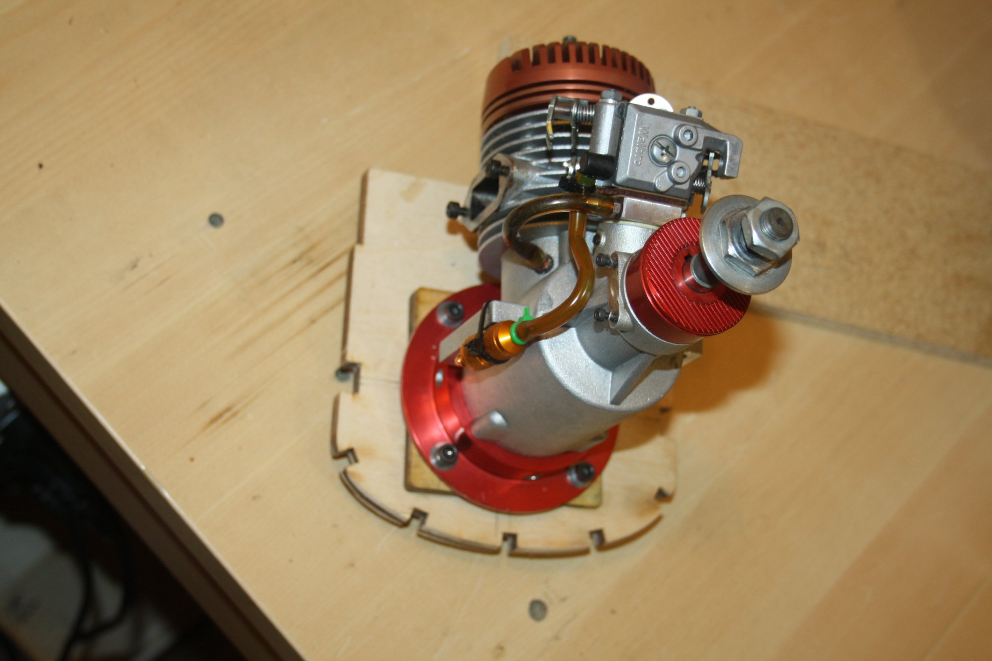
After some more work on the fuselage, laying balsa triplers (as in third layer, similar to doublers), and preparing former F7b (which is a sandwich of plywood and balsa), Once the "angled mounting spacer" was sanded to size, I was ready to check alignment (Please note that the engine will be placed inverted in the aeroplane and not as shown in the photos of the alignment check).
The engine lined up perfectly on the centre line at the prop hub with the correct right thrust, which allowed me to place lock-nuts on the back of the firewall. This is NOT my preferred method of installation, and I still hope that I will be able to reach the back of the firewall when the fuselage is complete with sufficient space for my hand to place nylock nuts on the engine mounting screws.
Cheers,
Eran
For reference, the U.S. Engines 41cc weight is 2,041g without muffler producing 3 BHP. This and the comment on Manni's linked thread lead me to select the MVVS 40cc for this build.
After some more work on the fuselage, laying balsa triplers (as in third layer, similar to doublers), and preparing former F7b (which is a sandwich of plywood and balsa), Once the "angled mounting spacer" was sanded to size, I was ready to check alignment (Please note that the engine will be placed inverted in the aeroplane and not as shown in the photos of the alignment check).
The engine lined up perfectly on the centre line at the prop hub with the correct right thrust, which allowed me to place lock-nuts on the back of the firewall. This is NOT my preferred method of installation, and I still hope that I will be able to reach the back of the firewall when the fuselage is complete with sufficient space for my hand to place nylock nuts on the engine mounting screws.
Cheers,
Eran
11-20-2020, 04:43 AM
#105
Thread Starter
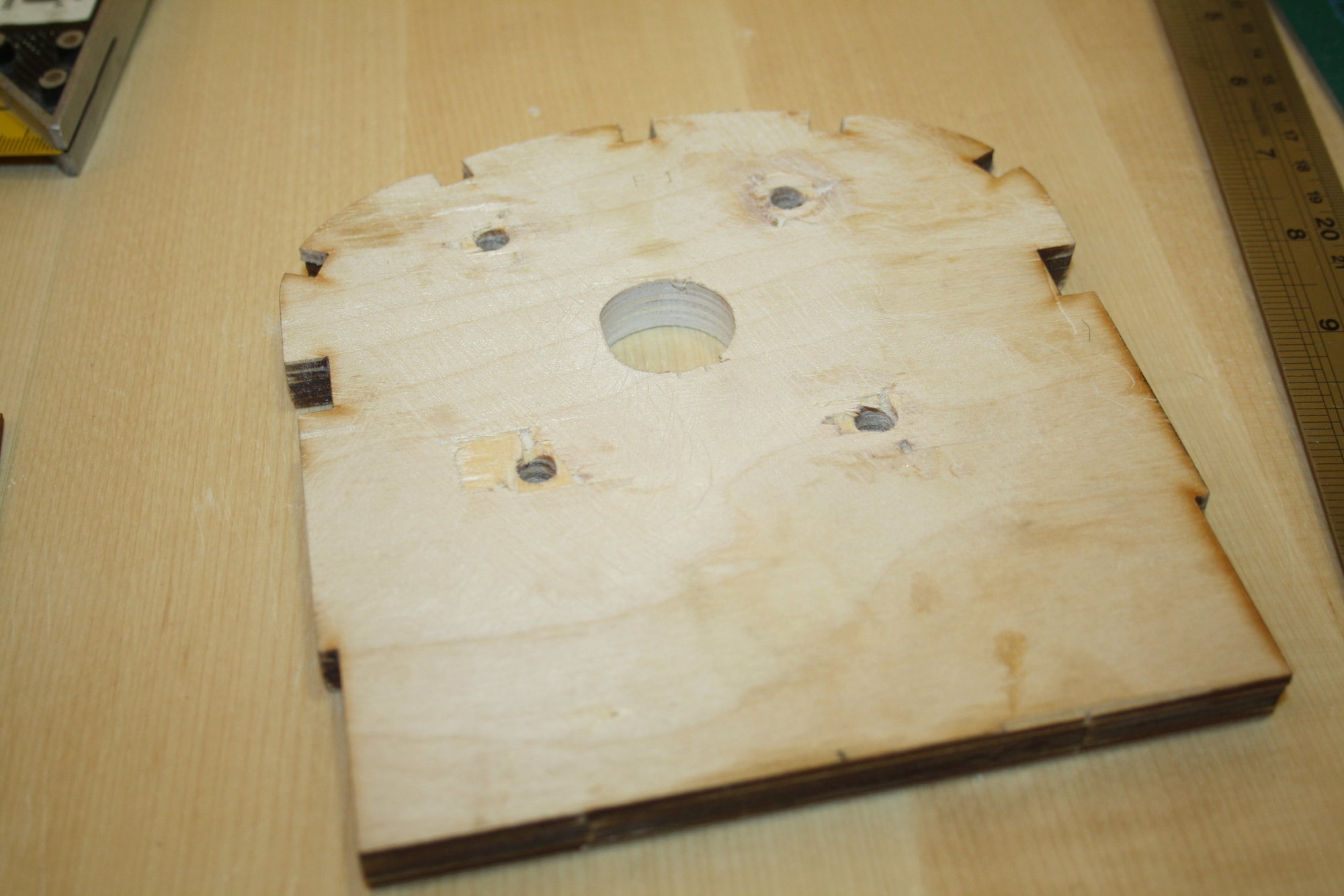
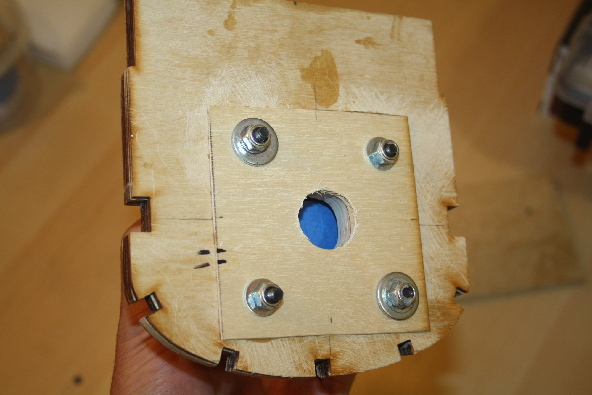
I was not happy with the engine mounting using the lock nuts after all, so I ripped it out.
I had to laminate the affected area with some additional birch plywood as some of the firewall own plywood was ripped off.
I decided to go ahead with Nylock nuts as it is my preferred method to secure engine mount screws and to figure out how to put them (and the washers) on the threads when the aeroplane will be completed...
Cheers,
Eran


 11-24-2020, 01:48 AM
#107
Thread Starter
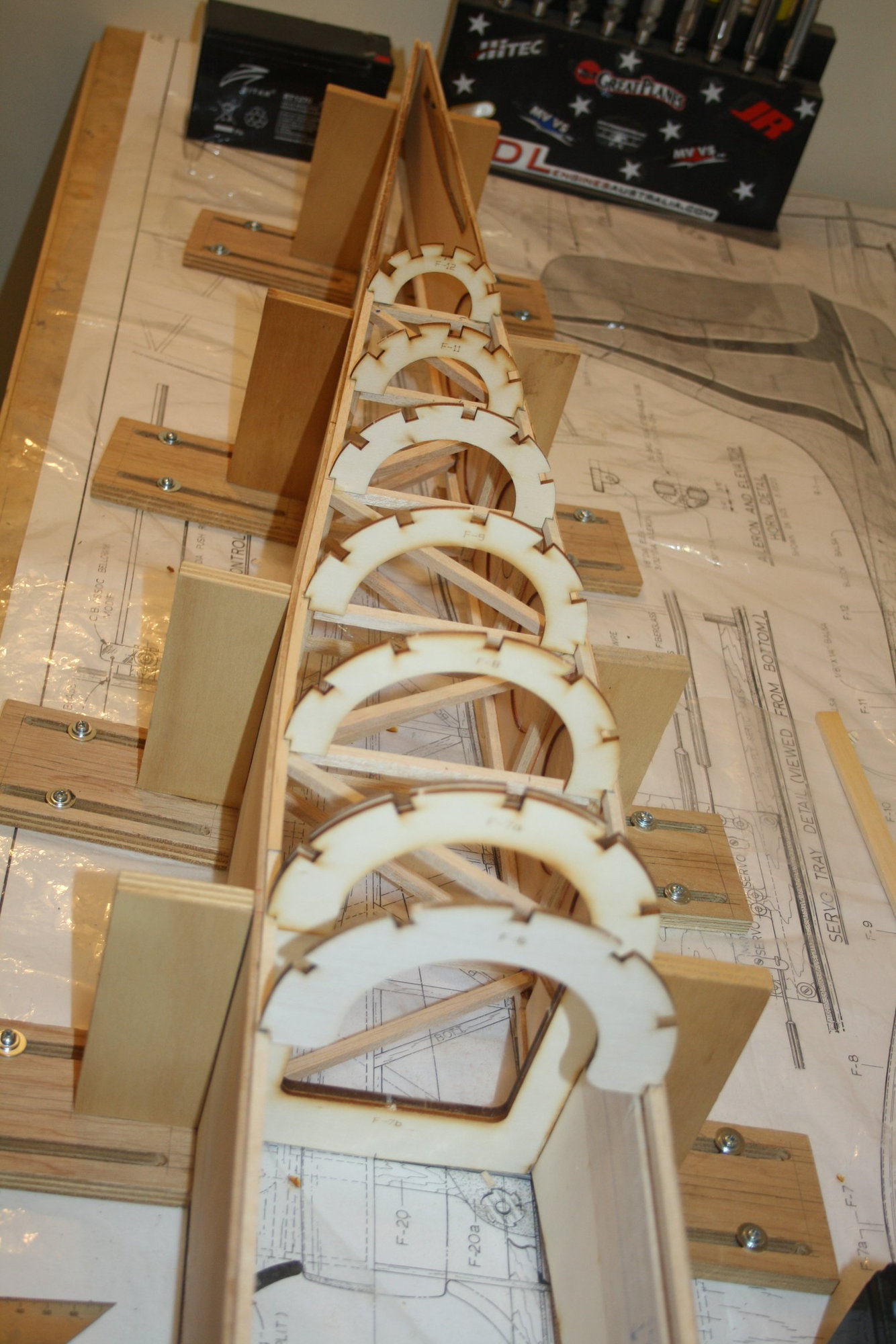
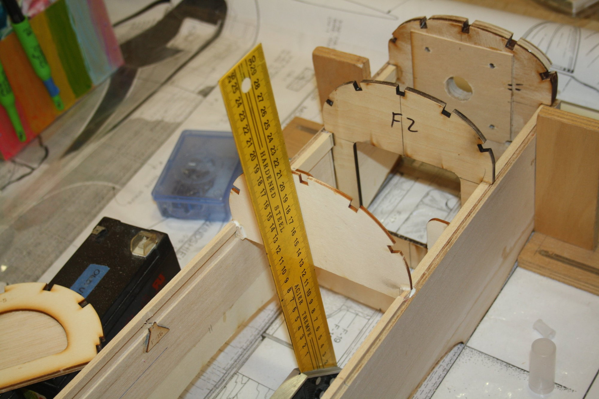
After measuring, aligning, re-measuring, aligning (etc.), the crucial gluing of the formers to the other fuselage side is now done.
Hopefully it is straight...
Cheers,
Eran
Hopefully it is straight...
Cheers,
Eran
 11-25-2020, 04:32 AM
#110
Thread Starter
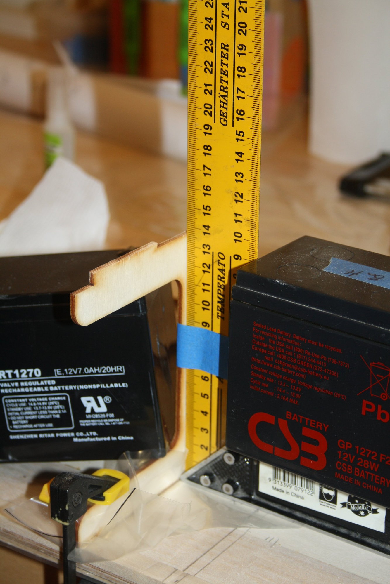
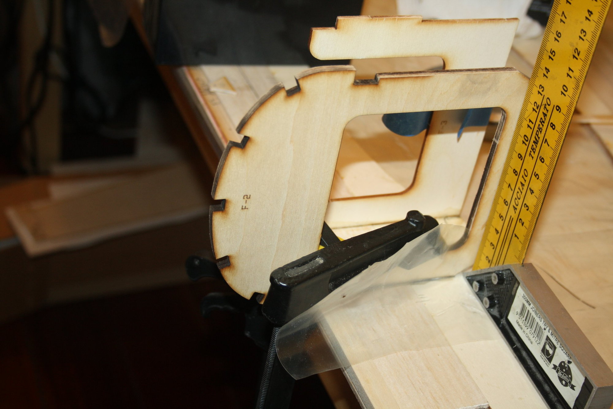
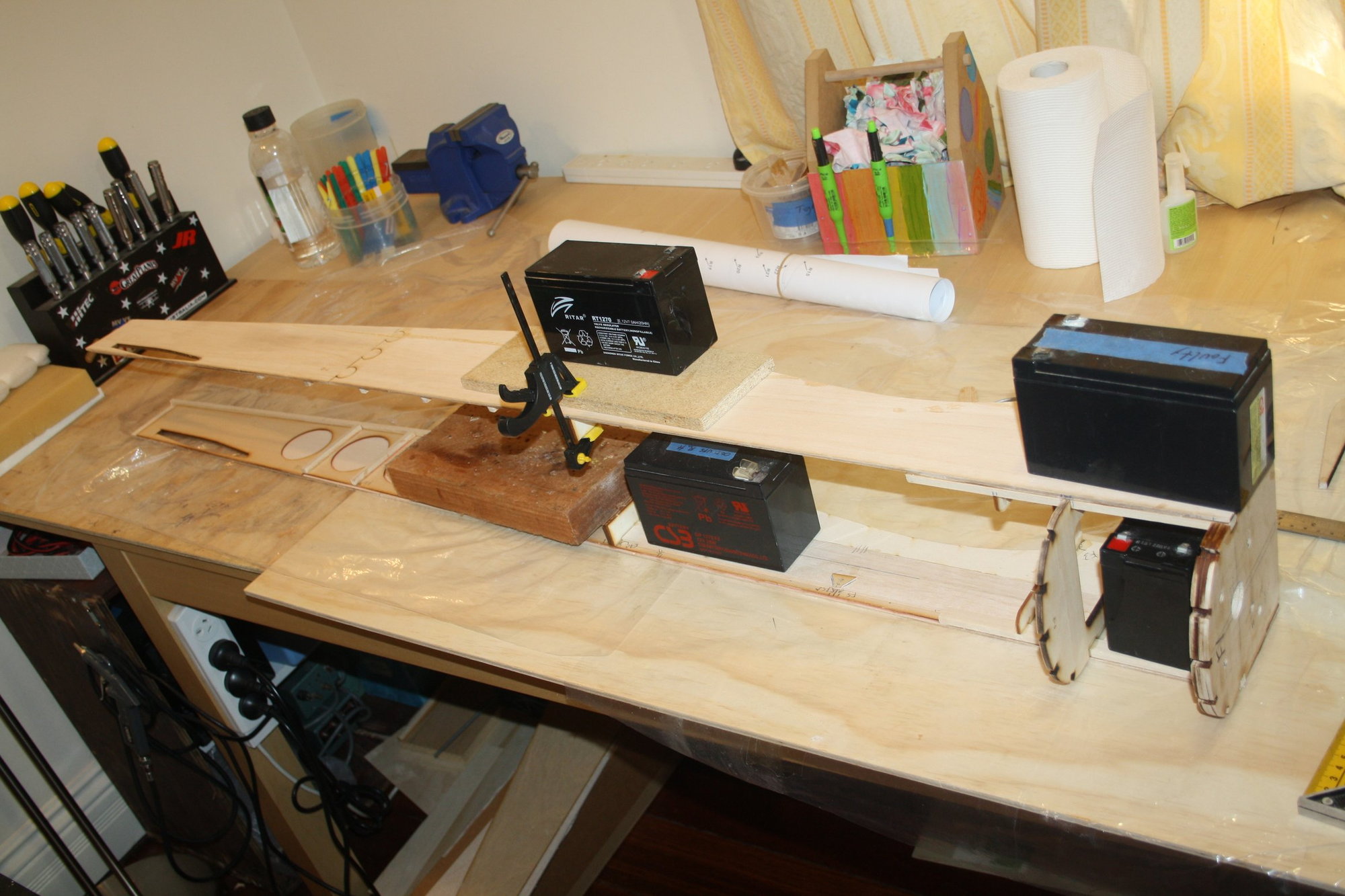
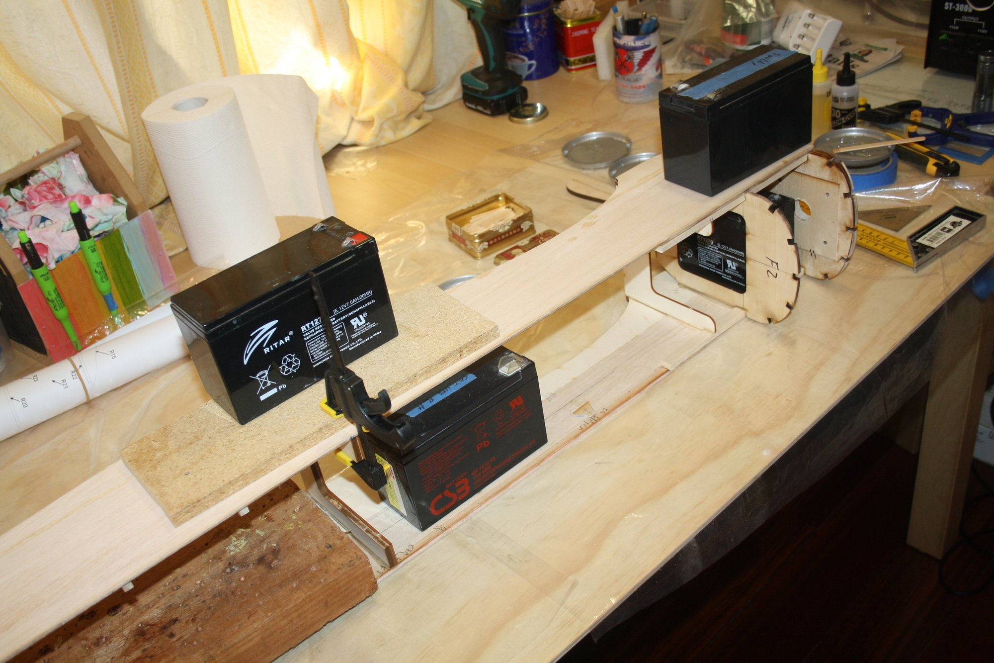
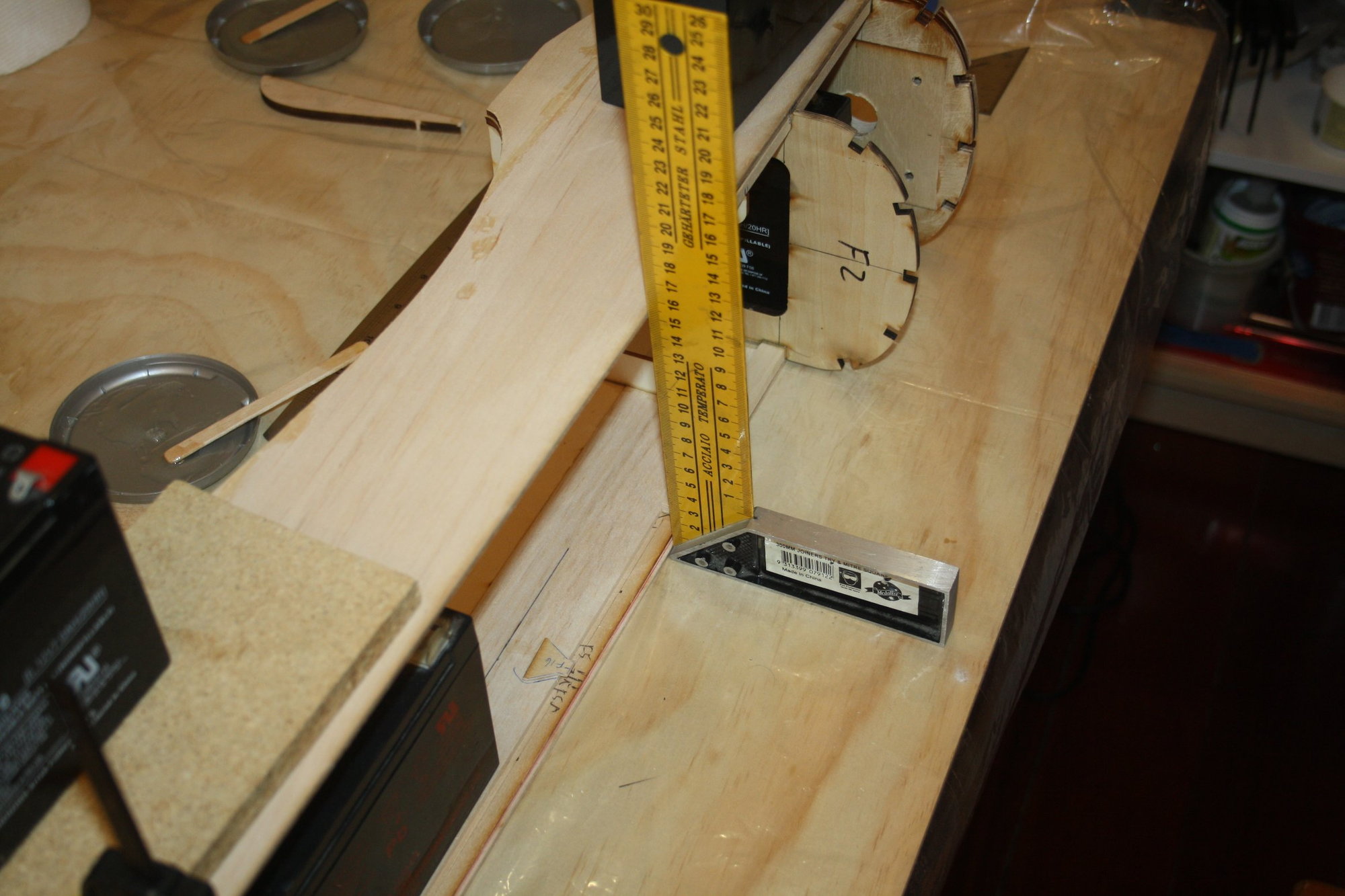
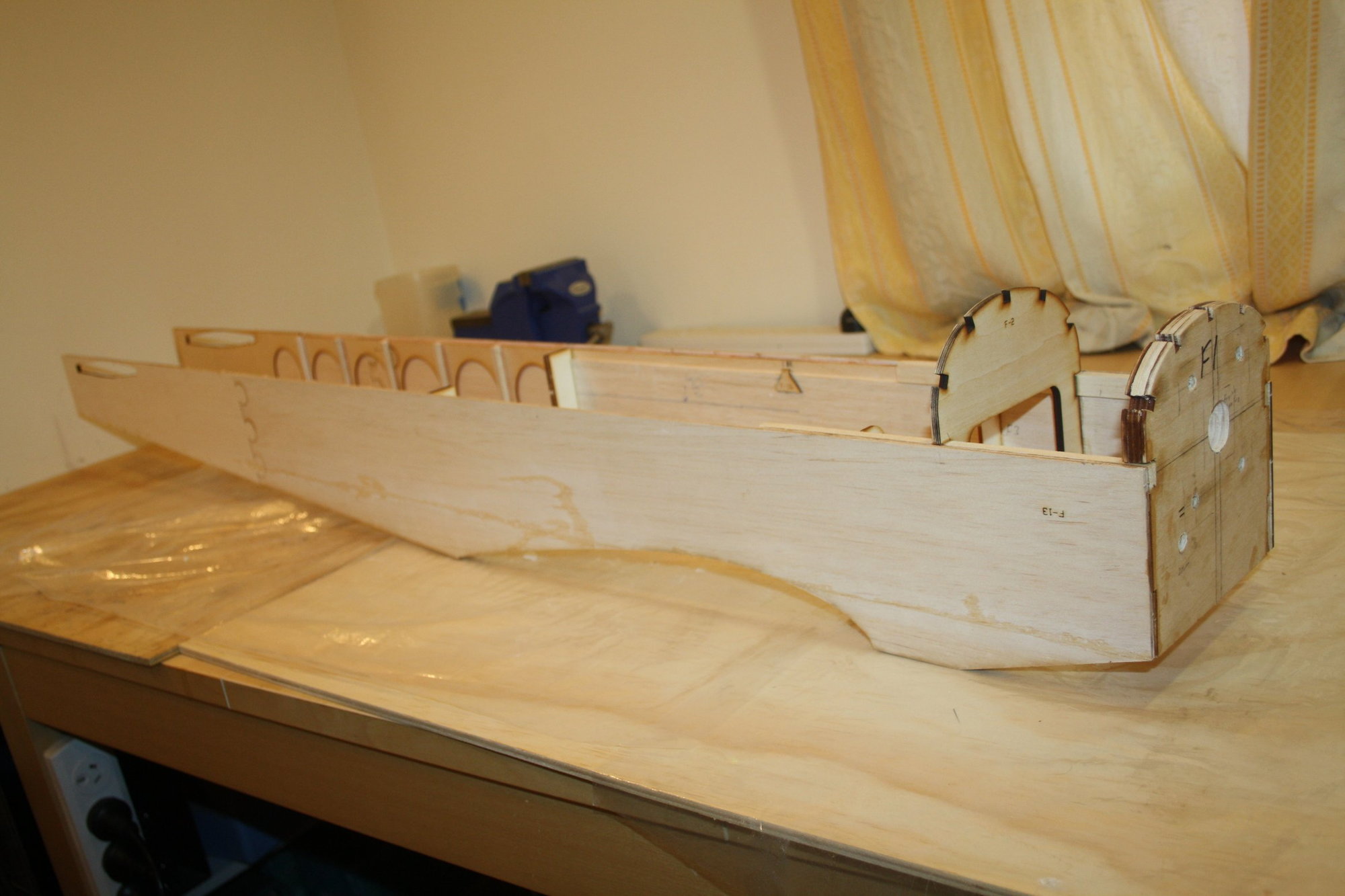
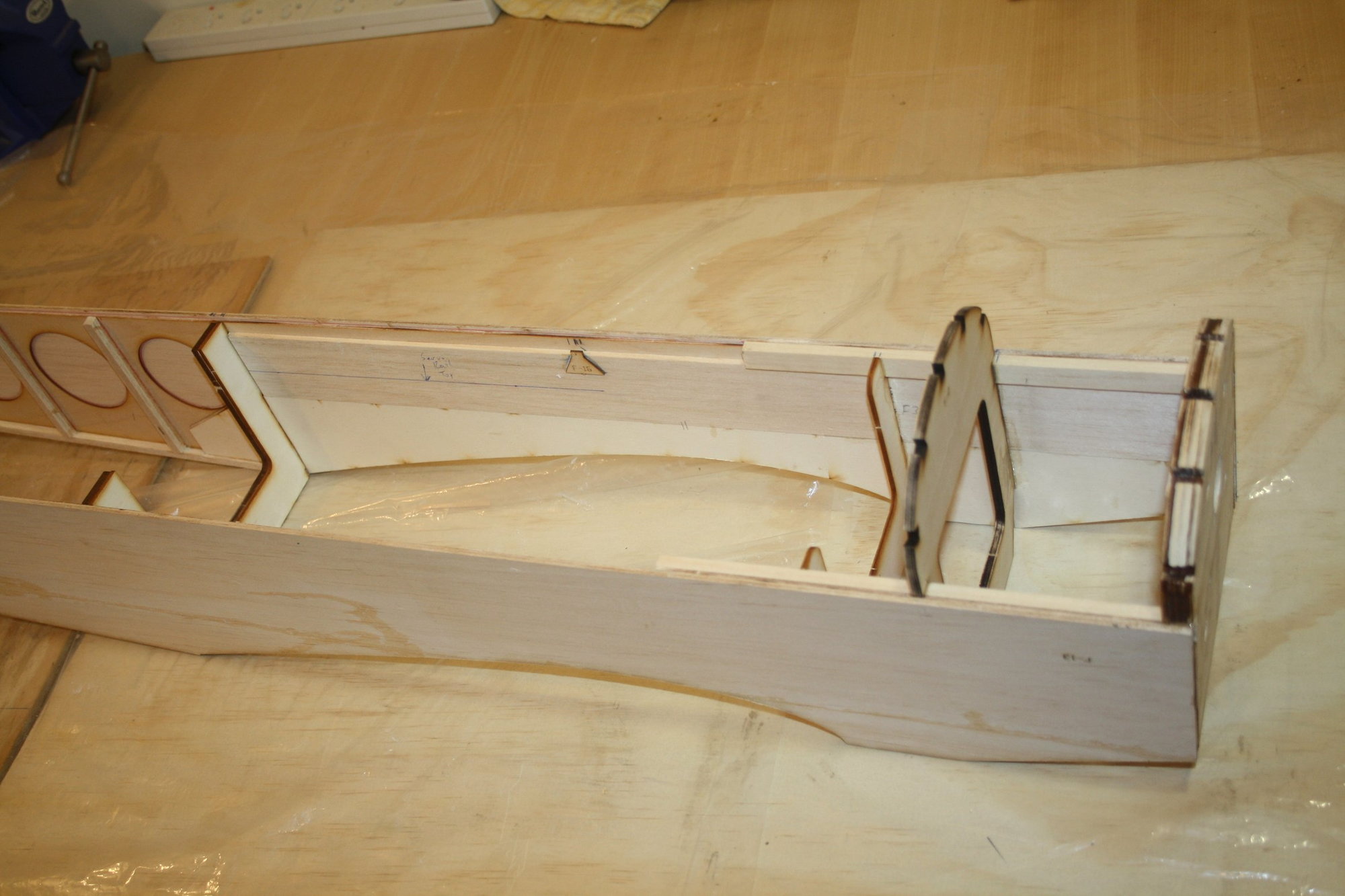
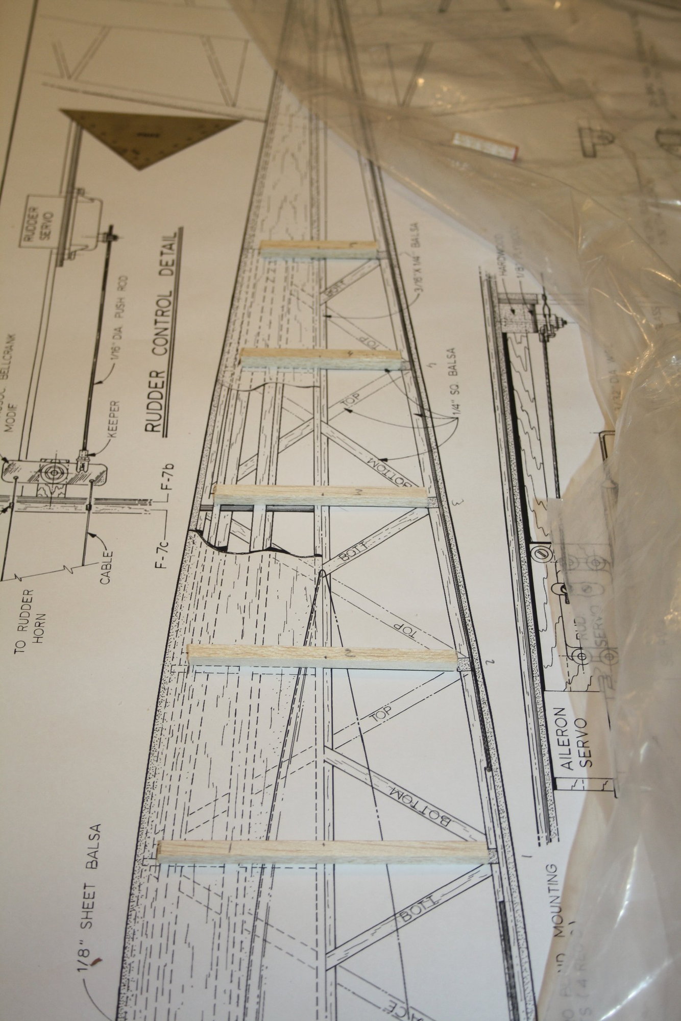
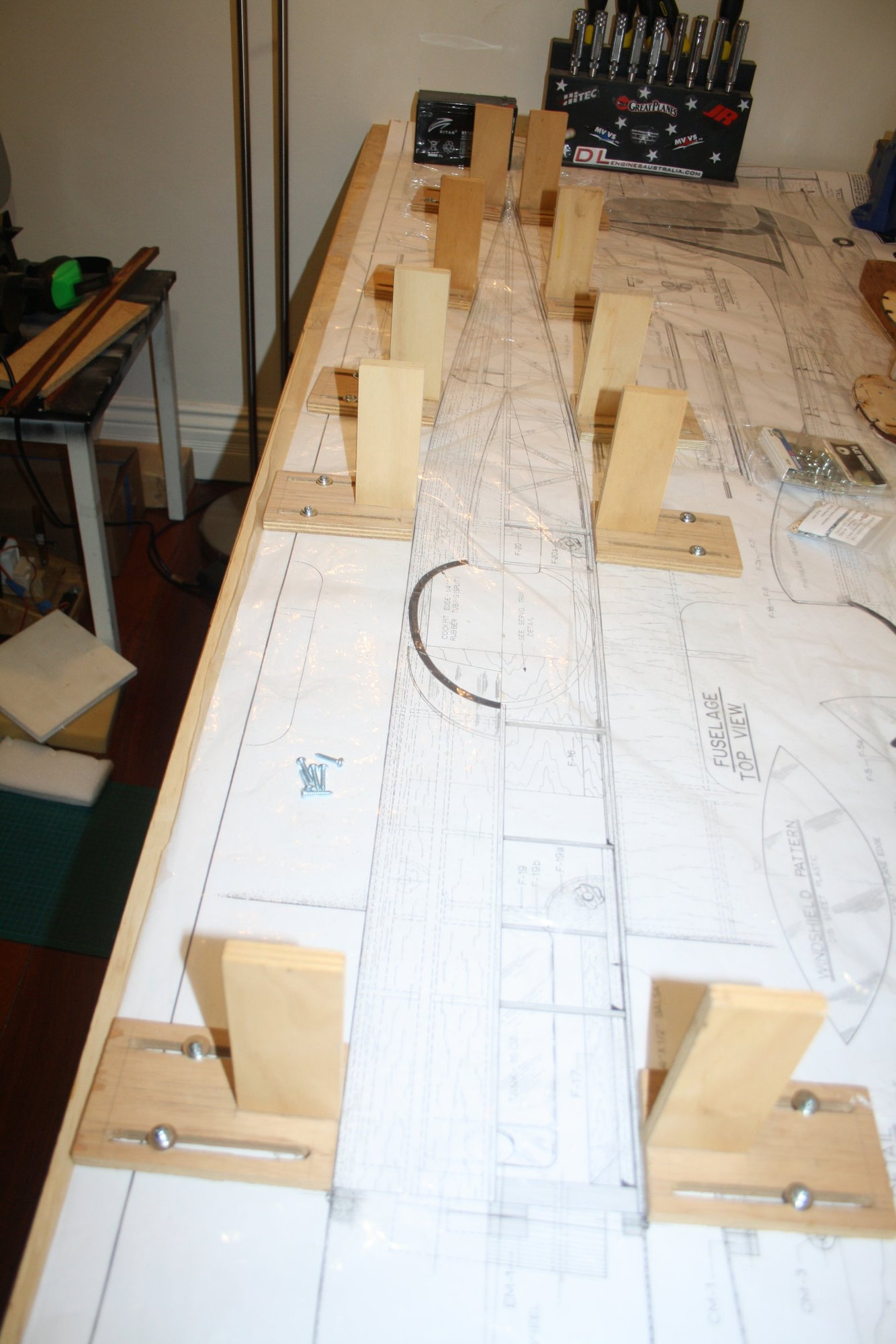
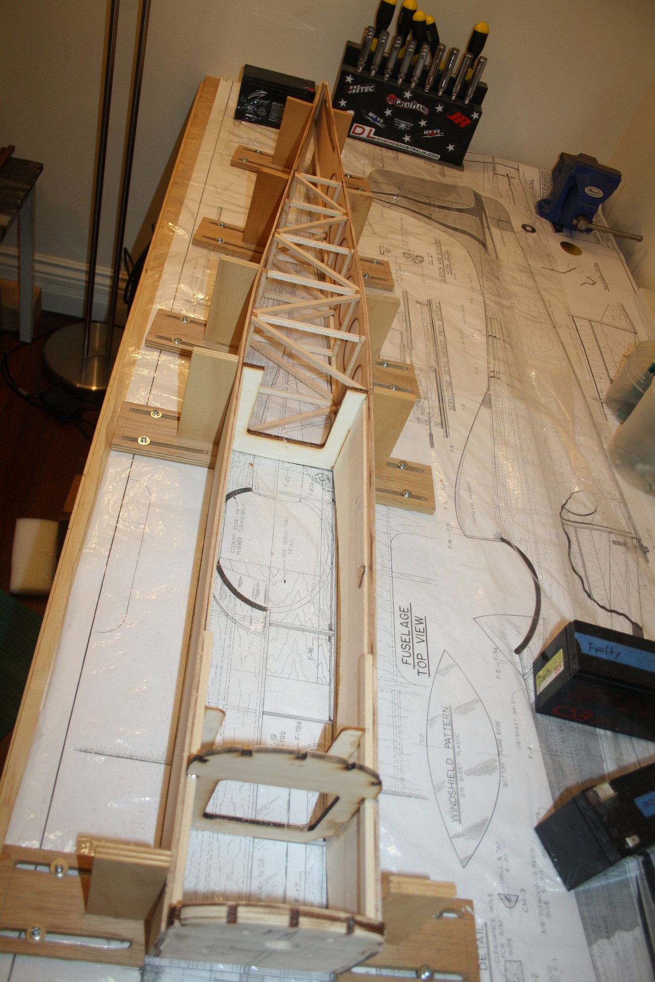
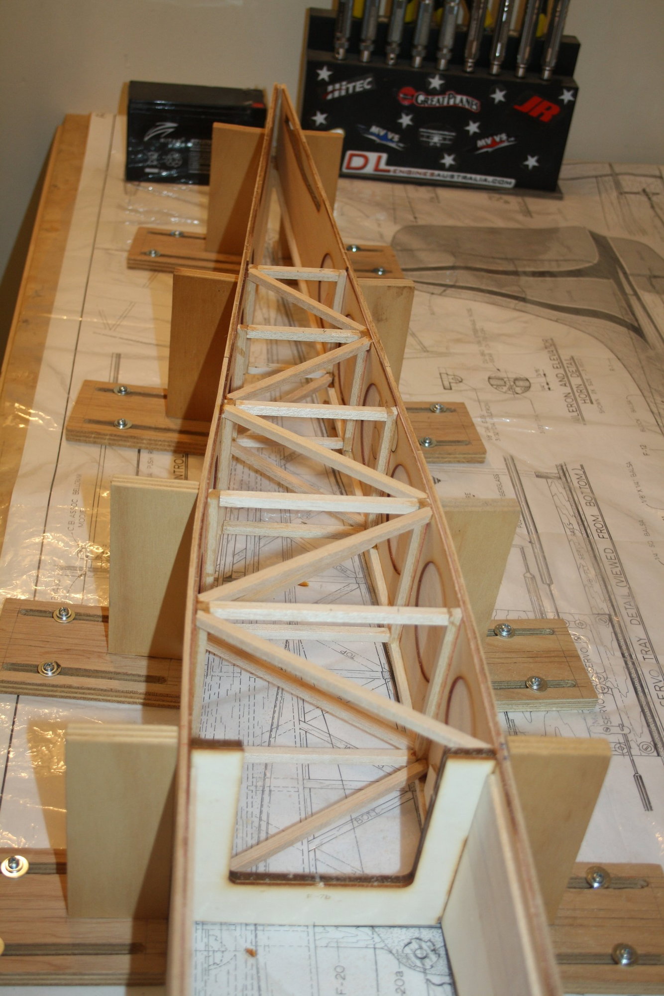
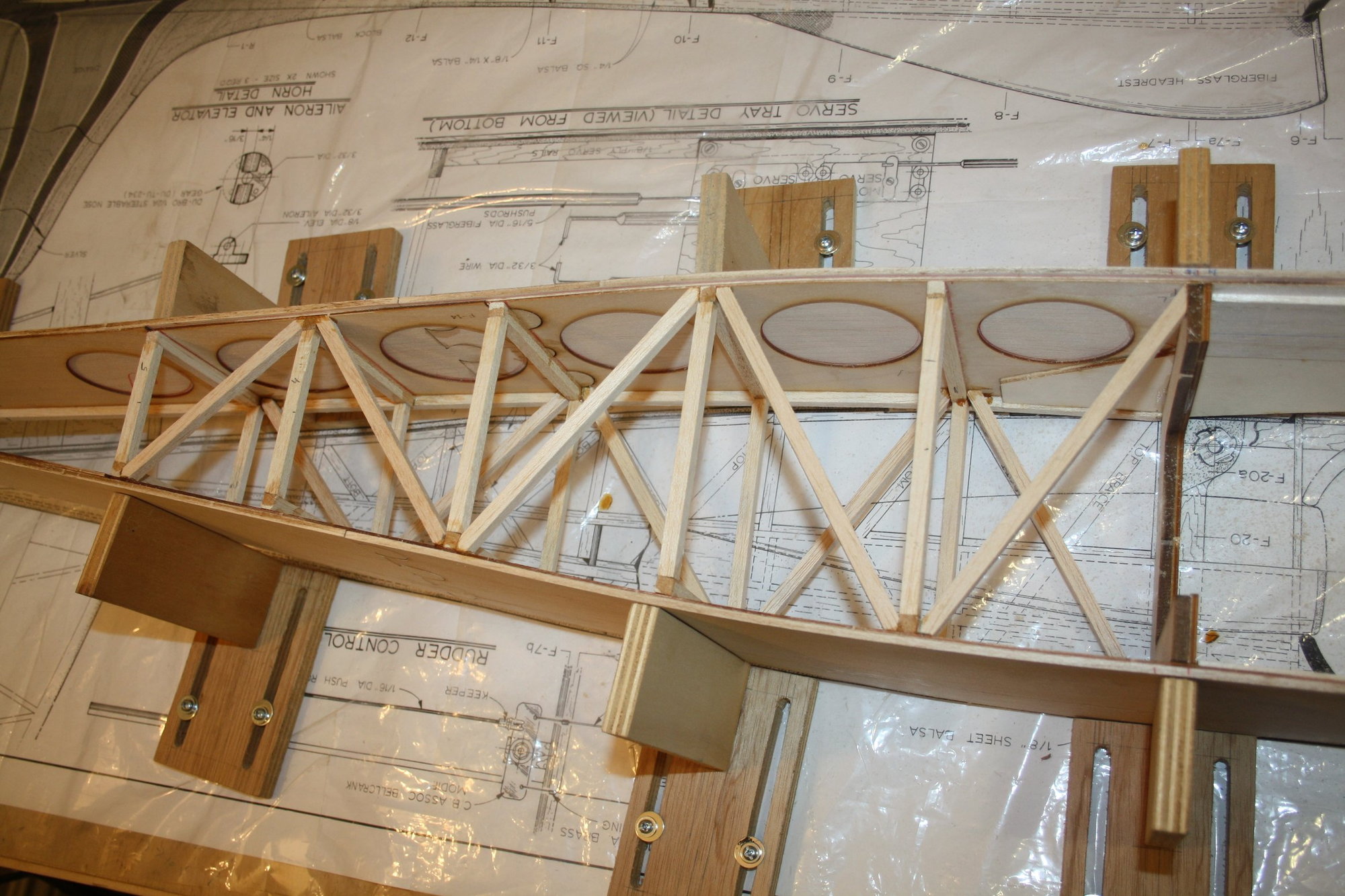
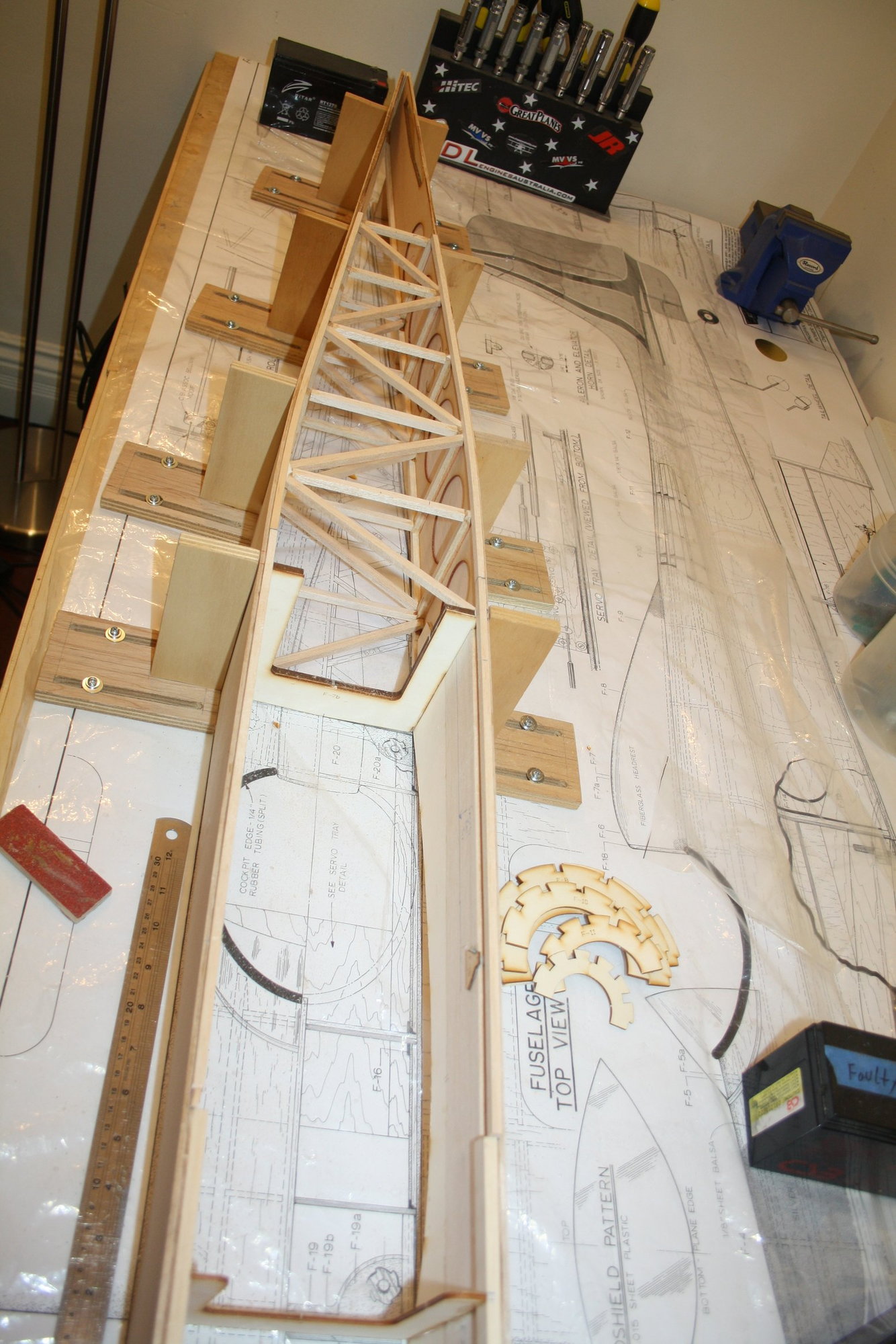
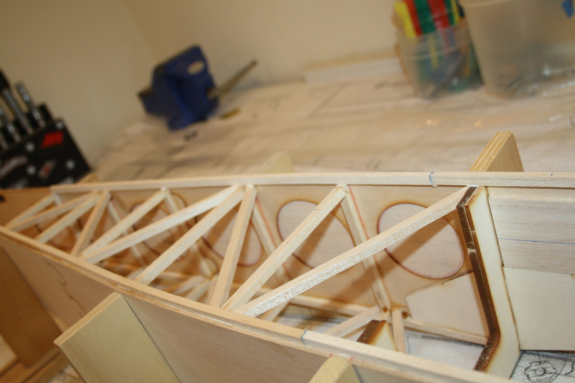
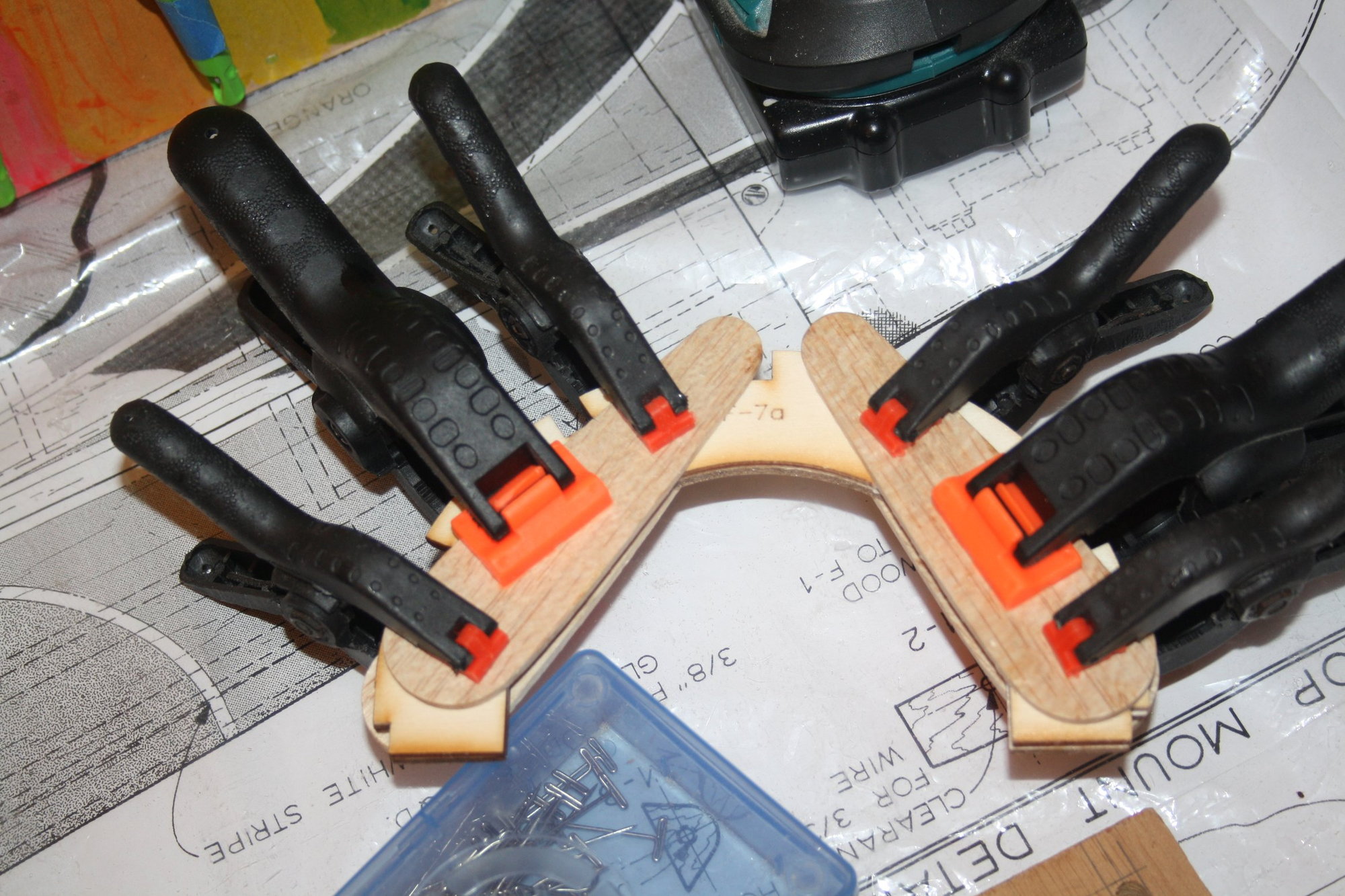
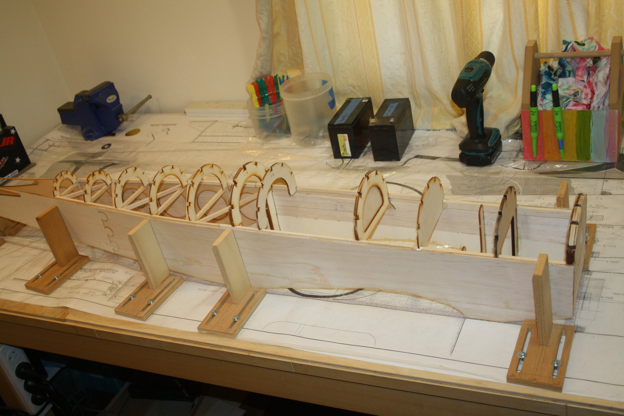
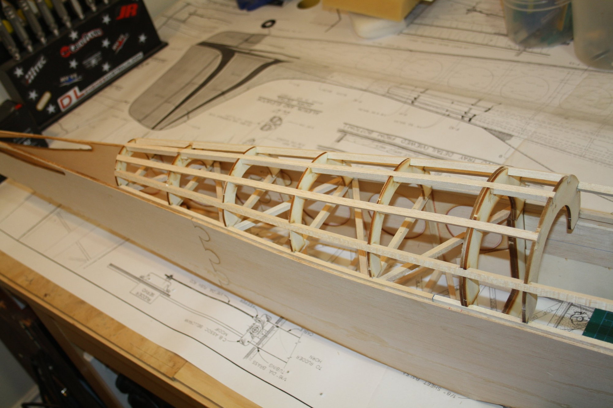
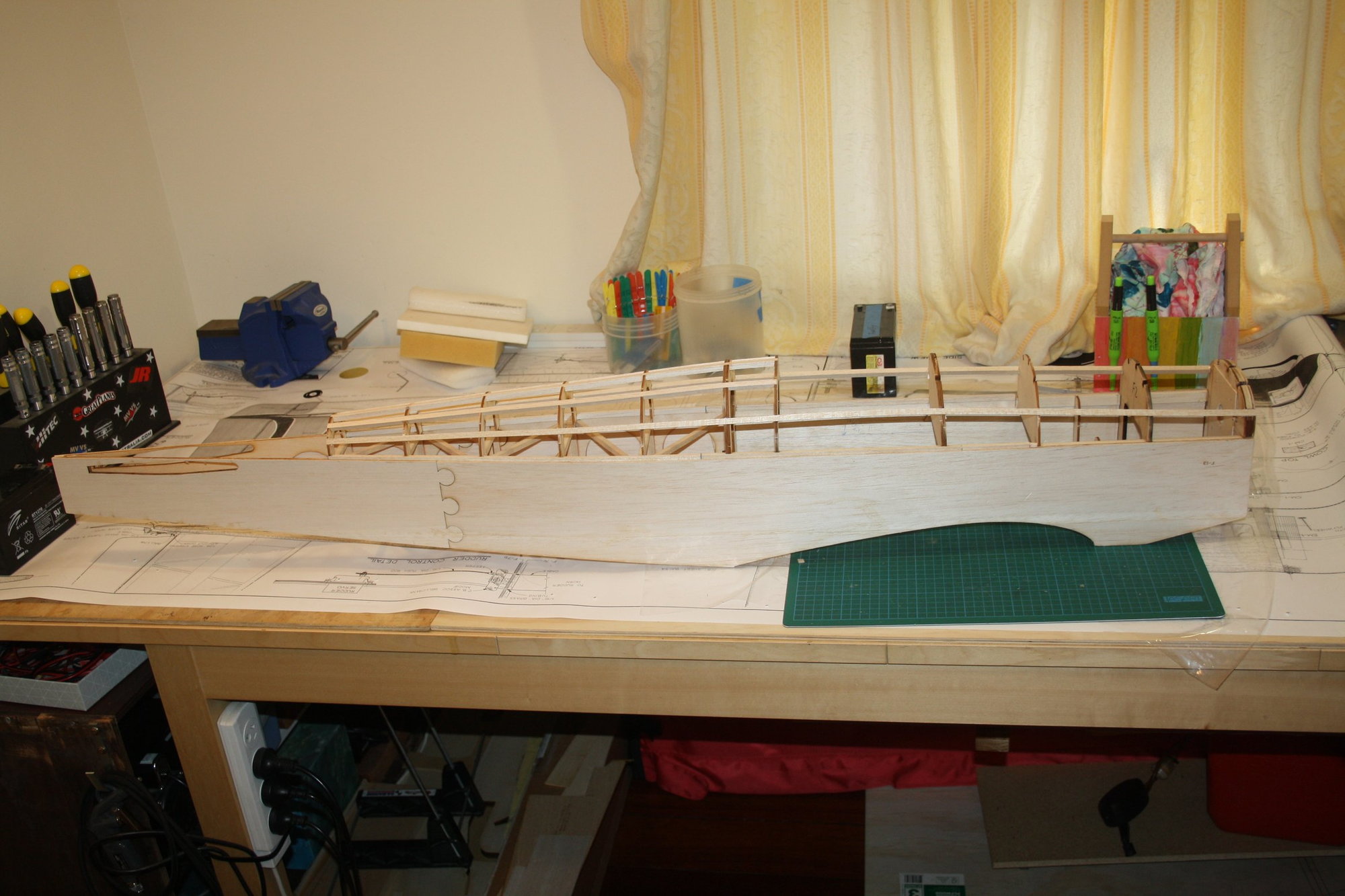
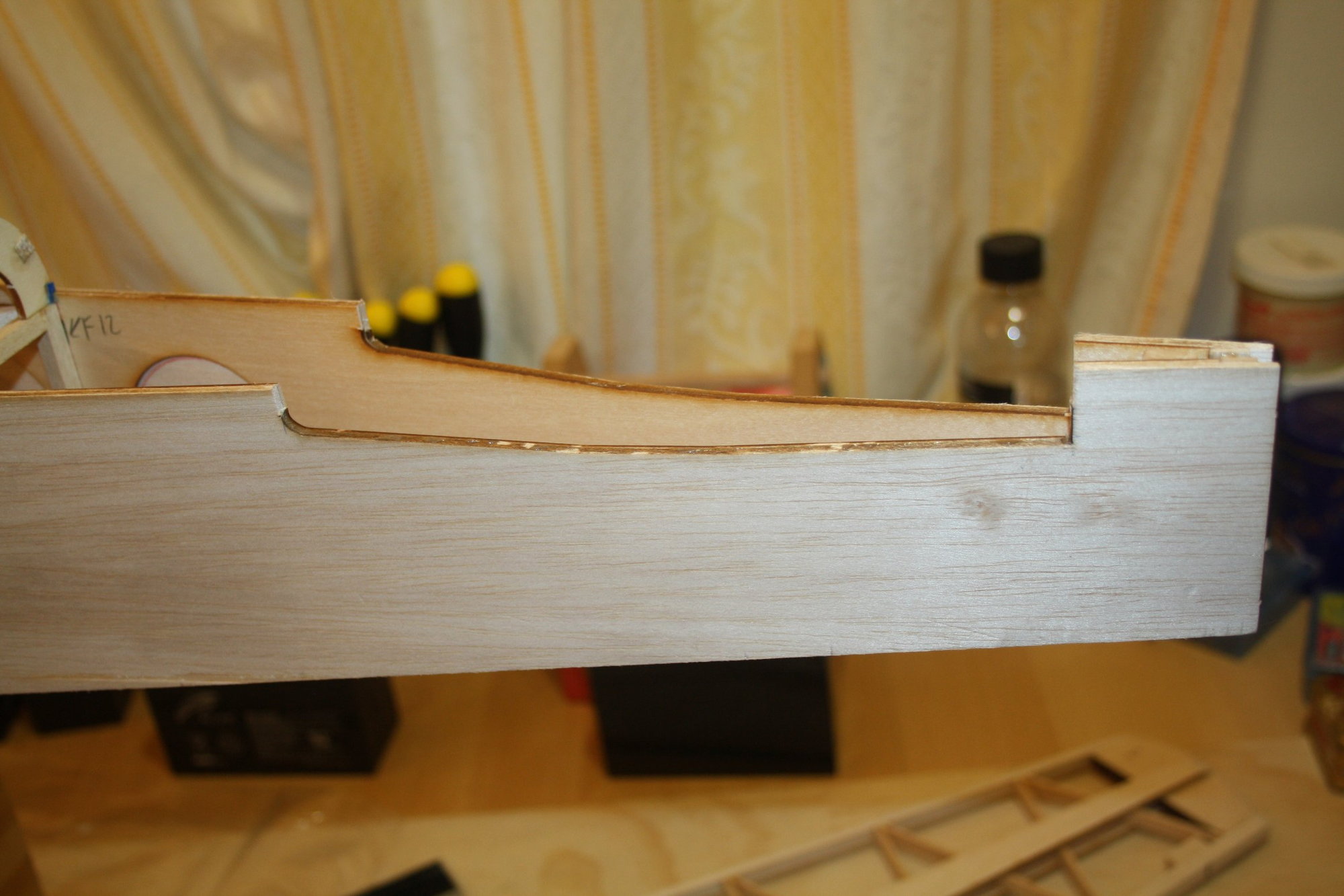
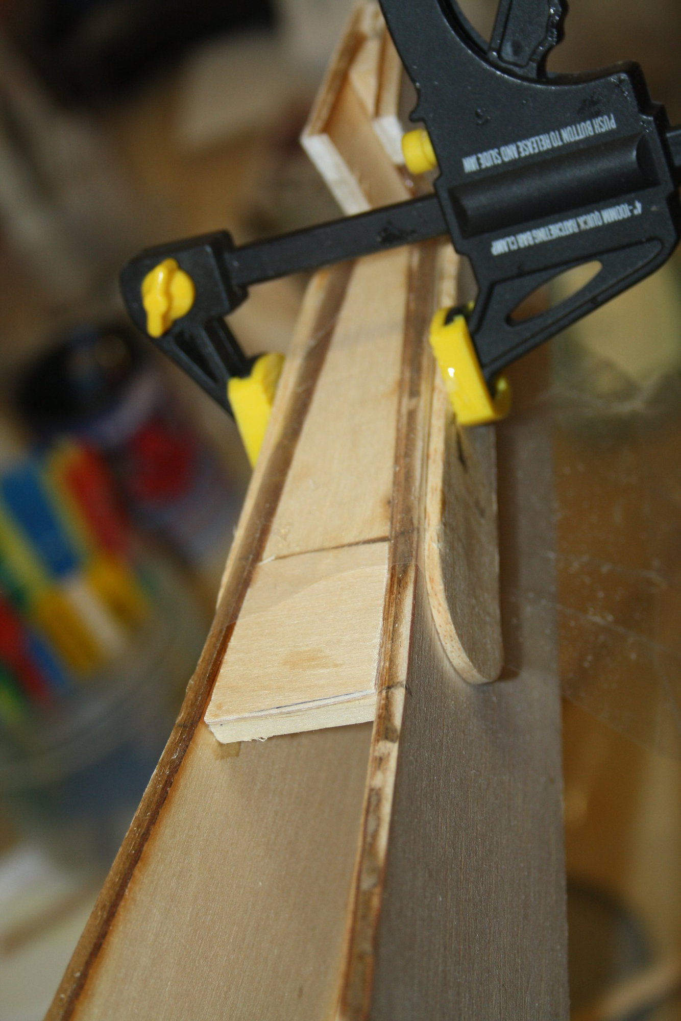
With the two sides glued to the formers at the "square section" (the front of the fuselage) and the assembly seems to be aligned properly with the plan, preparation work started for the fuselage rear section.
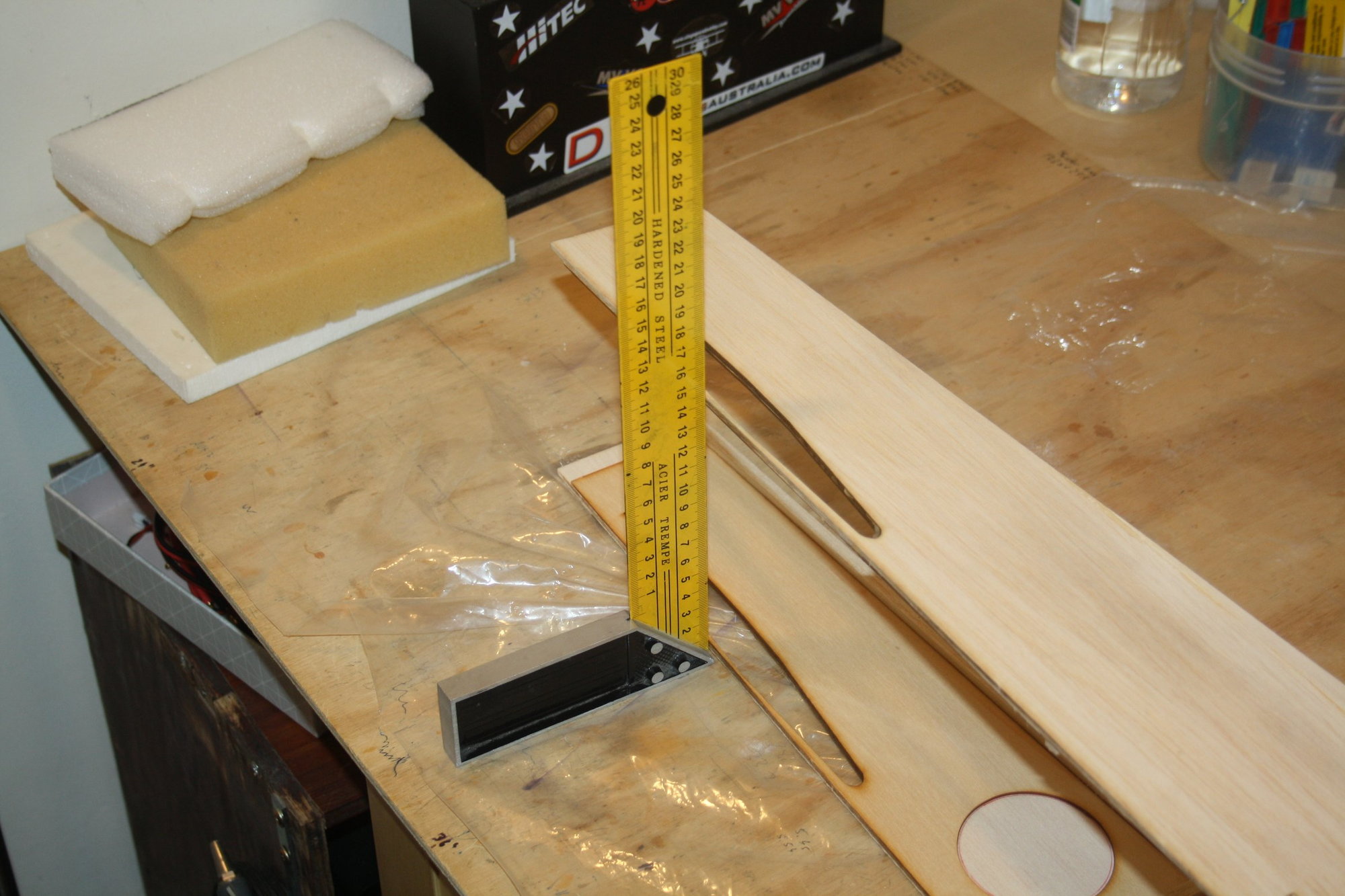
I glued balsa strips which together the plywood vertical fin post will join the rear-end of the fuselage;
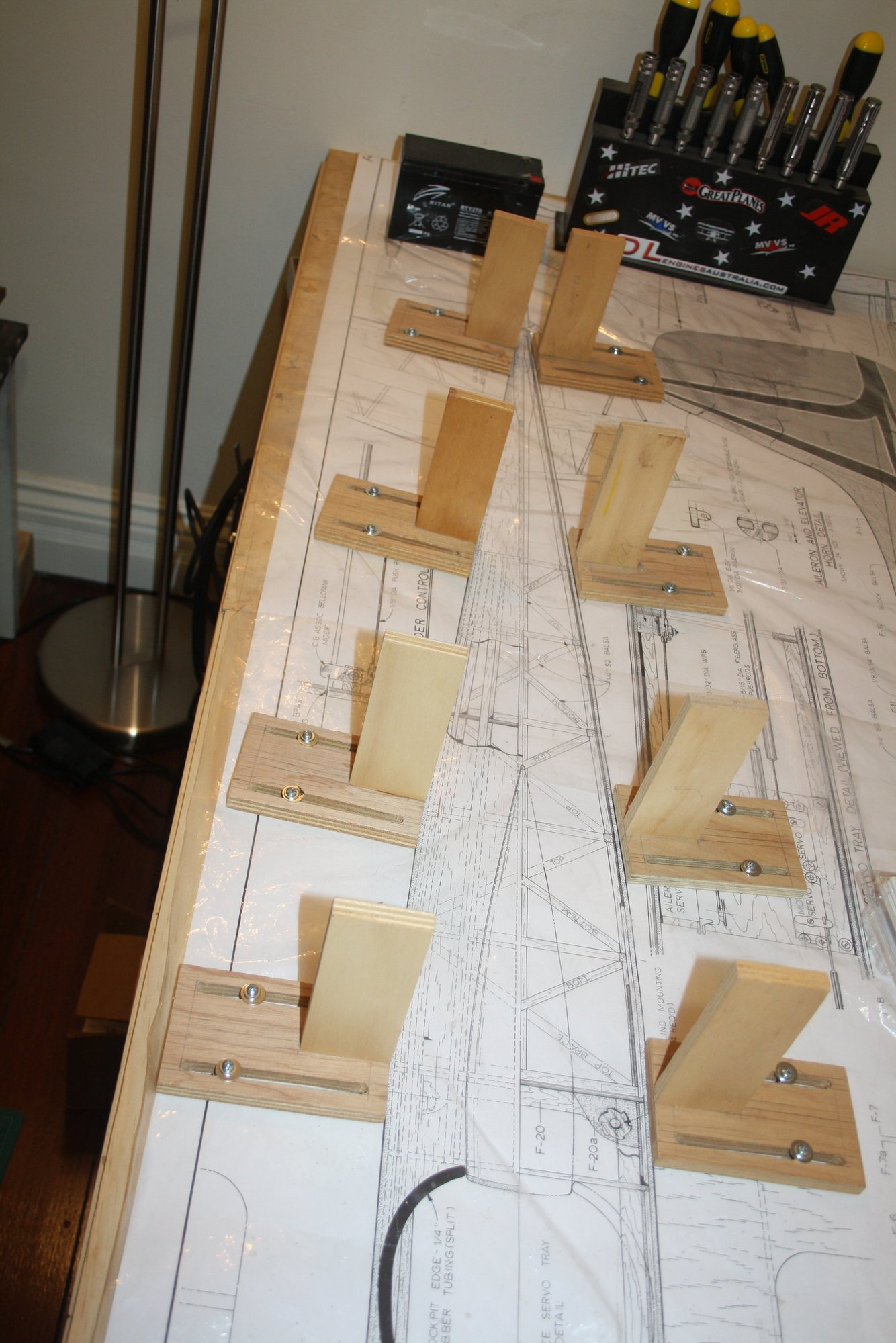
I pre-cut the balsa braces to length;
And finally, I assembled a jig in an attempt to have the fuselage sides "bends" as per the plan (it is not a straight line from former F7, the end of the square section, to the rear of the fuselage).
Cheers,
Eran
I glued balsa strips which together the plywood vertical fin post will join the rear-end of the fuselage;
I pre-cut the balsa braces to length;
And finally, I assembled a jig in an attempt to have the fuselage sides "bends" as per the plan (it is not a straight line from former F7, the end of the square section, to the rear of the fuselage).
Cheers,
Eran

 12-01-2020, 10:42 PM
#114
Thread Starter
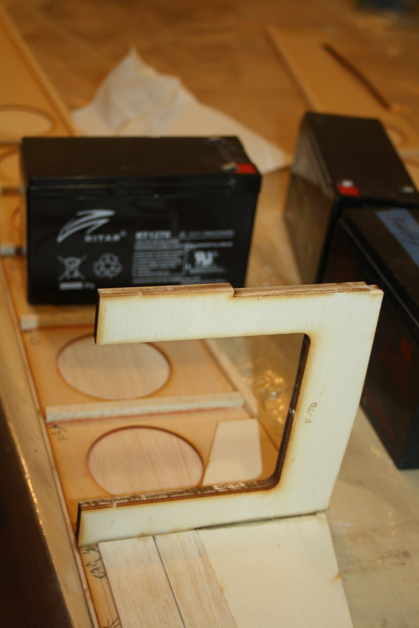
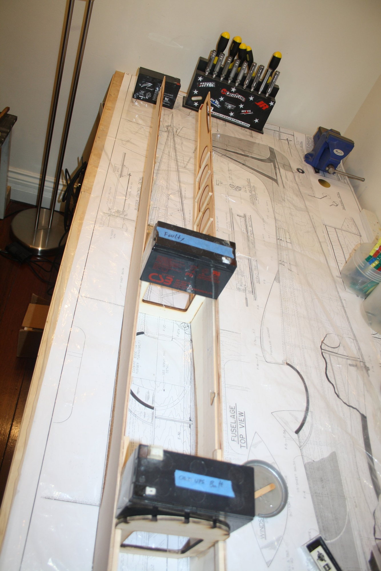
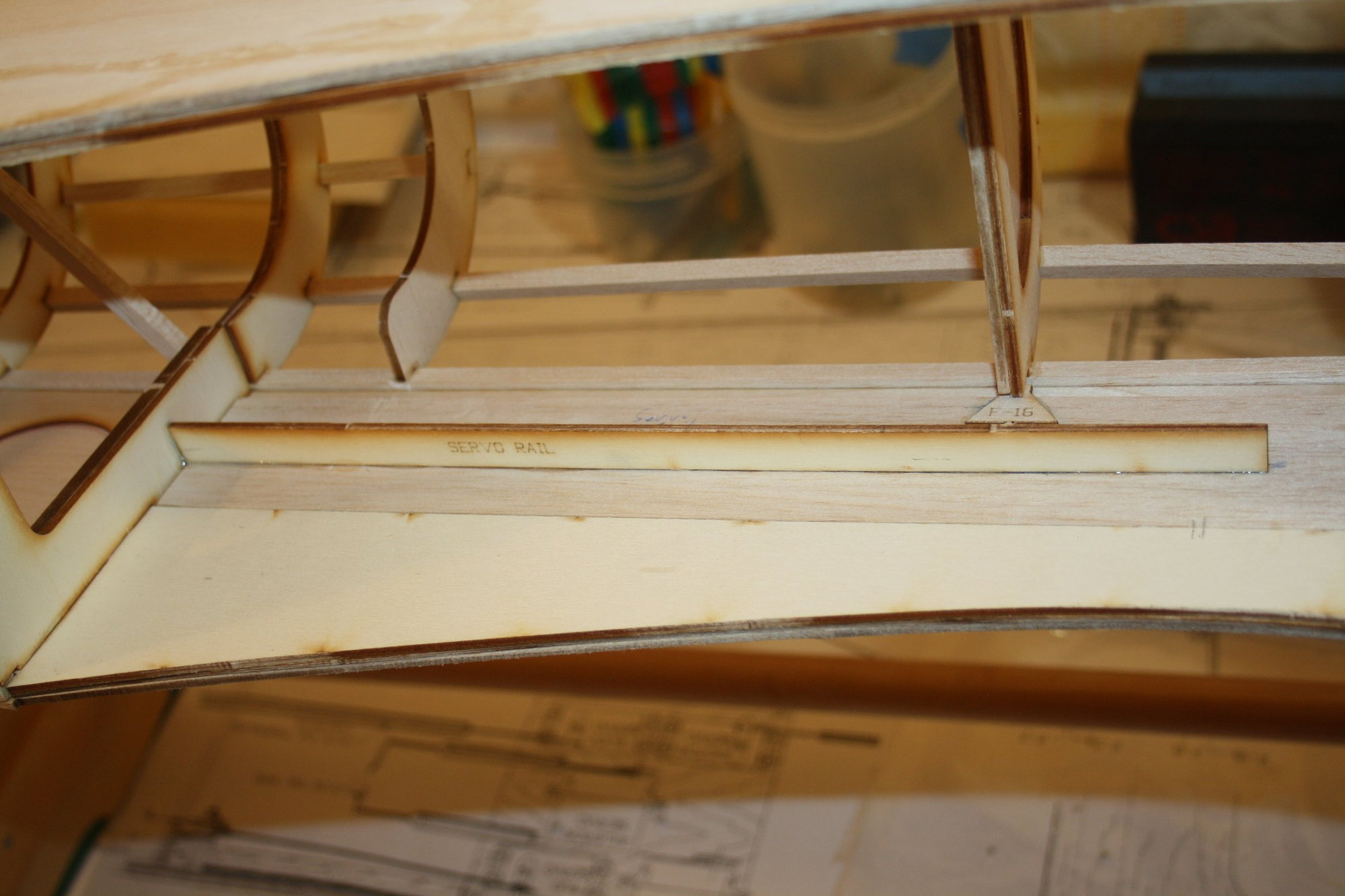
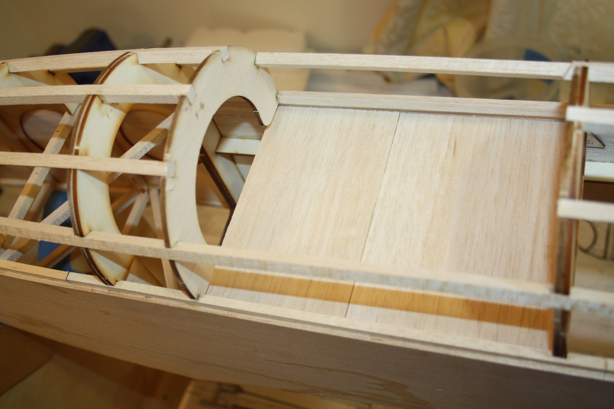
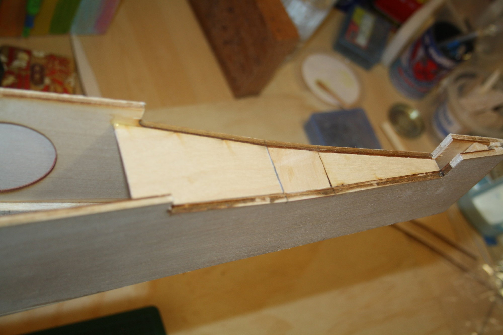
I glued the servo rails into place as it was convenient to do at this stage, as was gluing part "F7" to the fuel tank bay. I cannot understand why JB didn't use two triangle stocks for the task that "F7" is used for... As I could not be bothered with sanding the bottom section of "F7" into a triangle, I left it square.
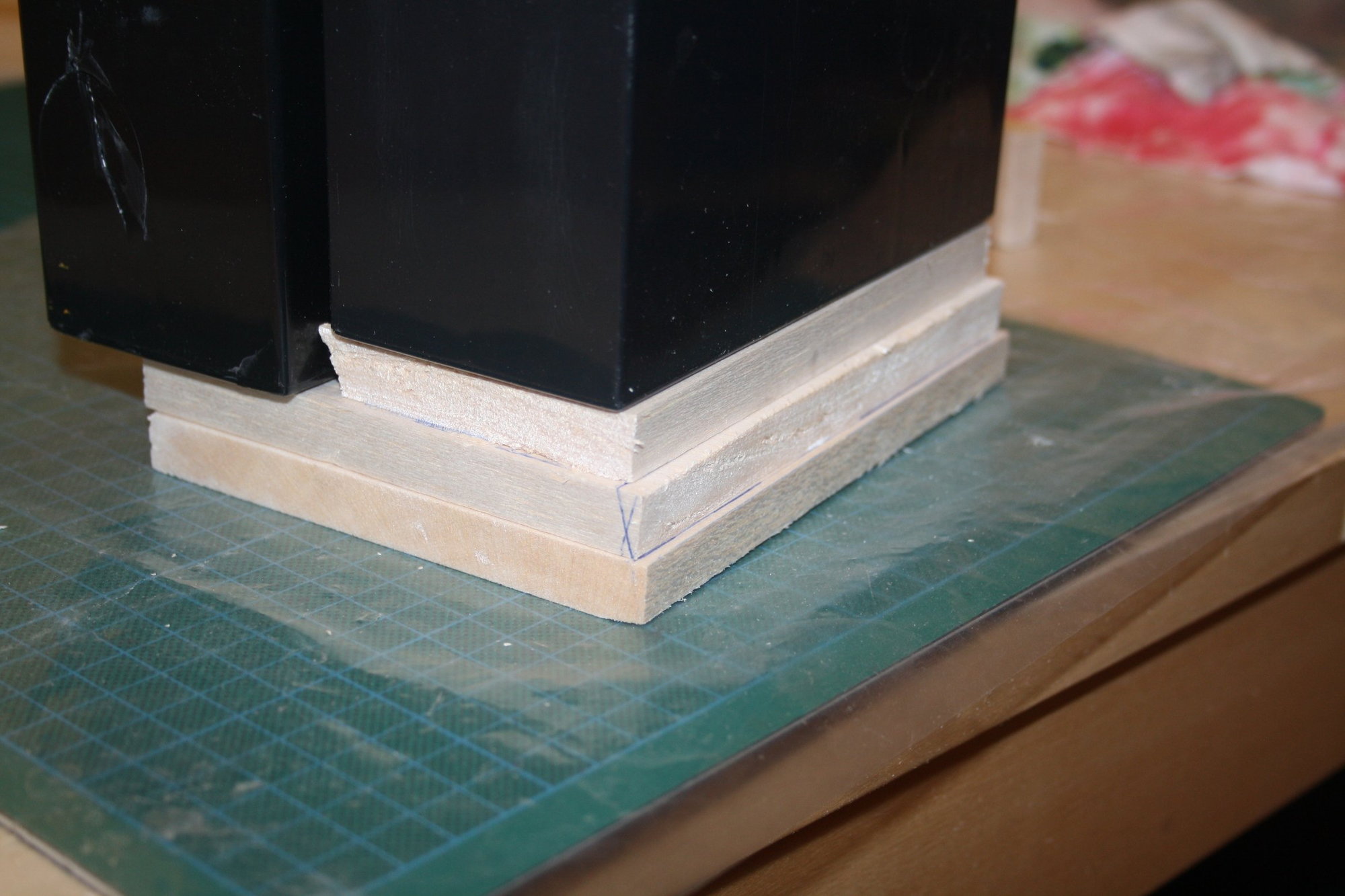
I then cut the cockpit floor from 3mm balsa (yet to be glued in case I need future access), glued the remaining stringers at the front and last for today, I started making the front bottom section of the aeroplane which is a thick balsa block (which I am laminating from thinner sheets).


Cheers,
Eran
I then cut the cockpit floor from 3mm balsa (yet to be glued in case I need future access), glued the remaining stringers at the front and last for today, I started making the front bottom section of the aeroplane which is a thick balsa block (which I am laminating from thinner sheets).
Cheers,
Eran
The following users liked this post:
Richard-V (12-10-2020)
12-03-2020, 04:10 AM
#115
Thread Starter
A mixed bag of a day in my Cave today.
While waiting on the balsa "block" glue to dry before I could start "sculpturing" it shape, I had a look into the horizontal stabiliser assembly.
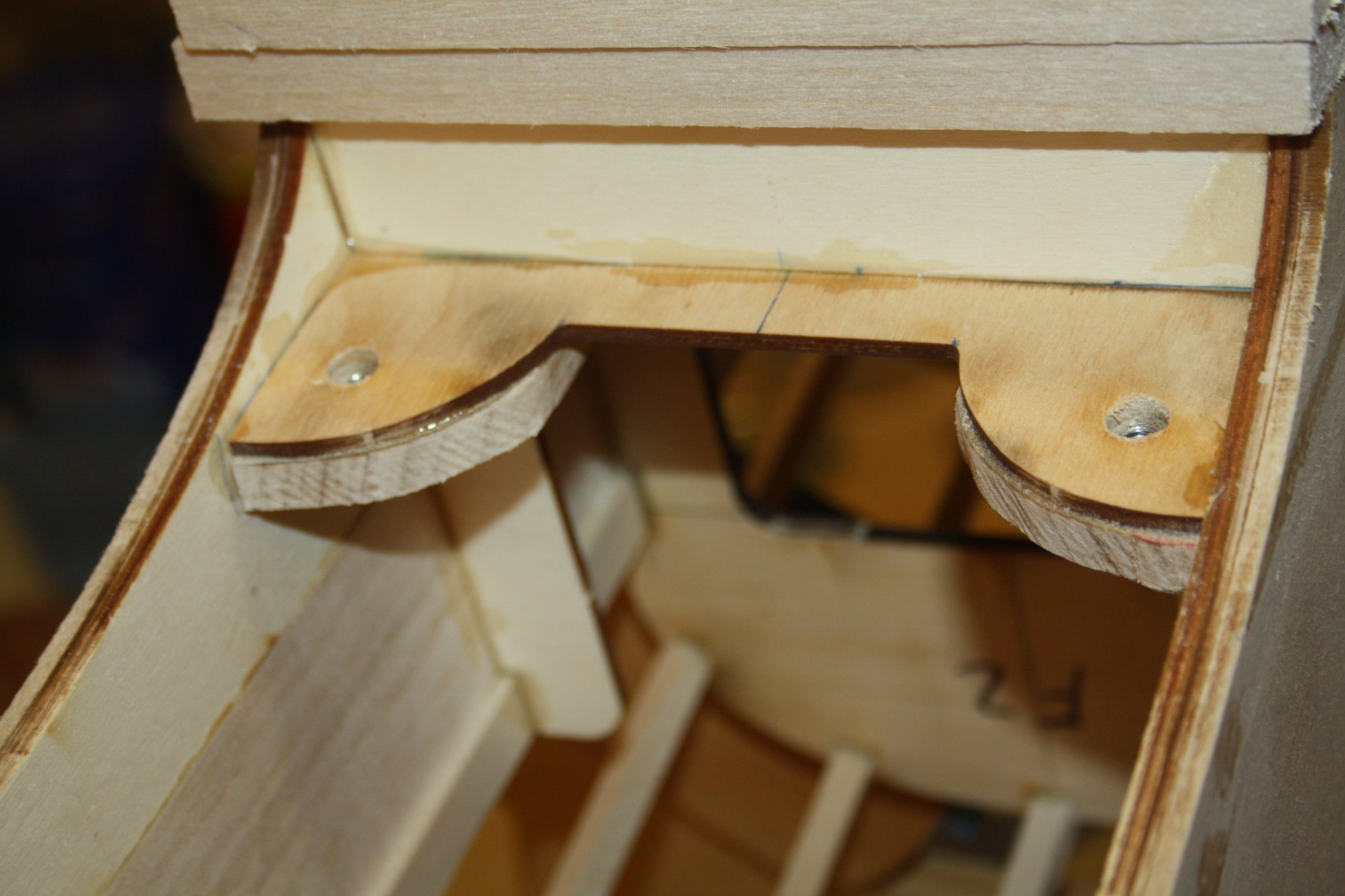
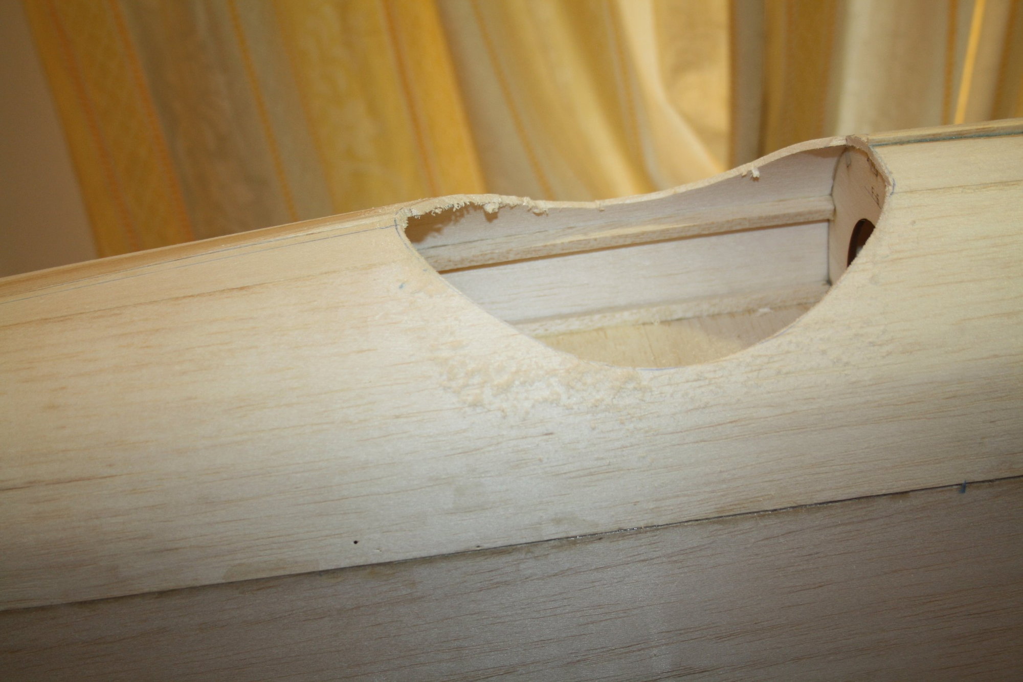
I decided to cut the top section of the fuselage sides at the location just above the horizontal stabiliser as the fit through the pre-cut slot did not allow inserting the horizontal stabiliser into place easily. While looking into the assembly I decided that I want to see the alignment in relation to the wing prior to going any further with glue. This led me to make and glue into place the wing mounts.
Cheers,
Eran
While waiting on the balsa "block" glue to dry before I could start "sculpturing" it shape, I had a look into the horizontal stabiliser assembly.
I decided to cut the top section of the fuselage sides at the location just above the horizontal stabiliser as the fit through the pre-cut slot did not allow inserting the horizontal stabiliser into place easily. While looking into the assembly I decided that I want to see the alignment in relation to the wing prior to going any further with glue. This led me to make and glue into place the wing mounts.
Cheers,
Eran
The following users liked this post:
Richard-V (12-10-2020)
 12-07-2020, 04:15 AM
#117
Thread Starter
After 5 months of waiting, I gave up on being able to get Monokote (or anything really) from Tower Hobbies with their current boycott of International customers. No other way to sugar-coat it, a disgraceful behaviour by the owner Horizon Hobbies. Being a loyal customer for many years, I am displeased to say the least.
I just managed to sourced 5 rolls of Monokote for my primary colour in Australia for $48AUD each (Ouch!). The reason I needed the covering now is that I prefer covering prior to installing major components.
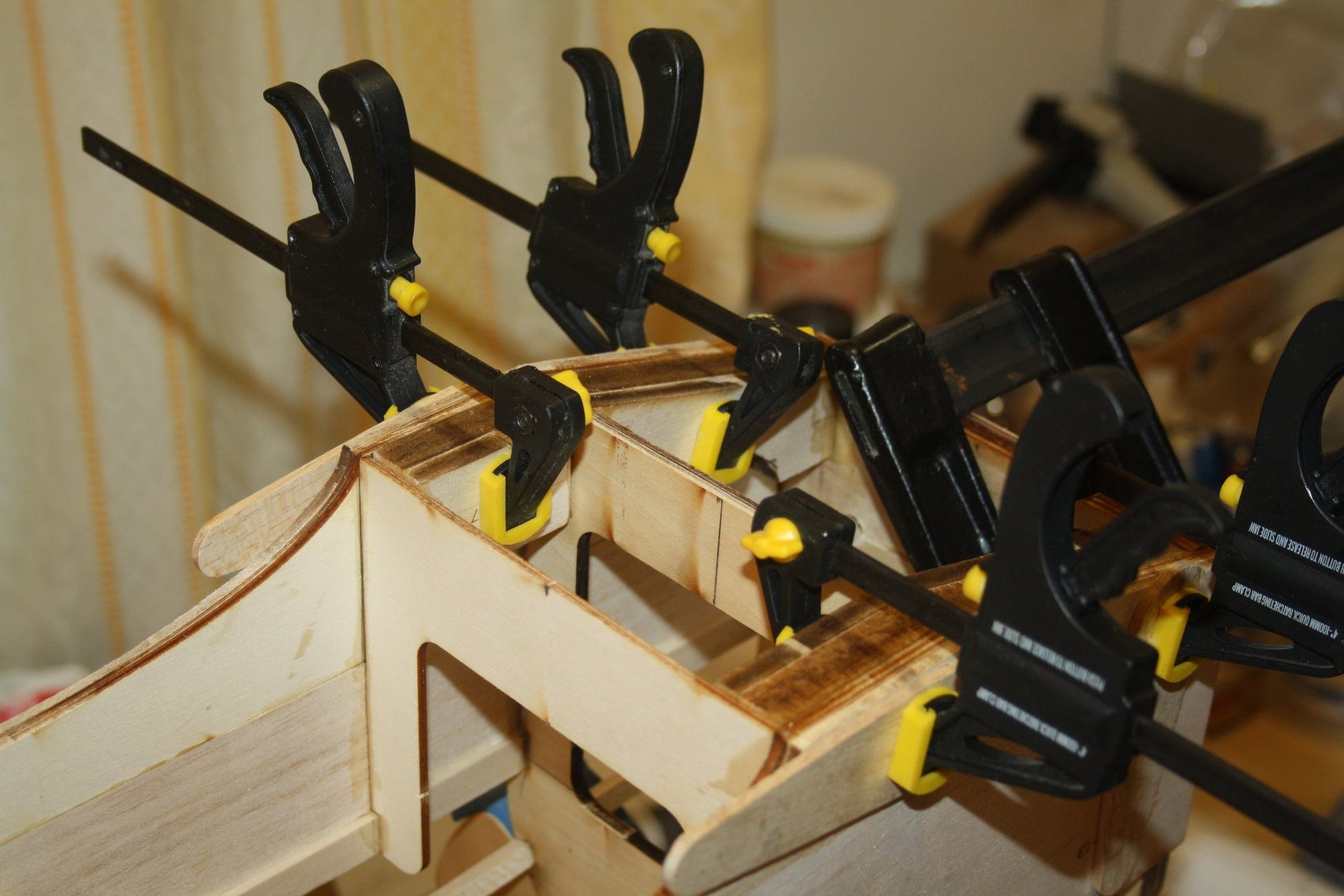
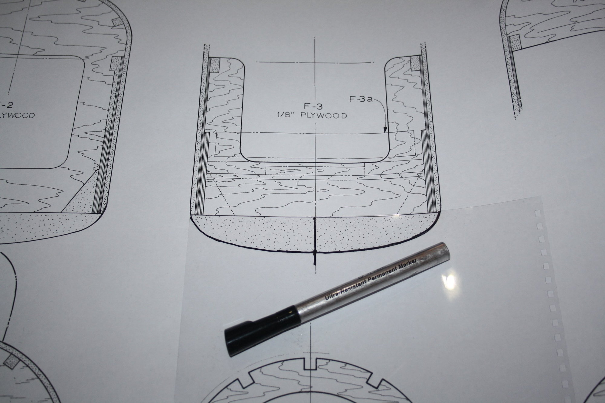
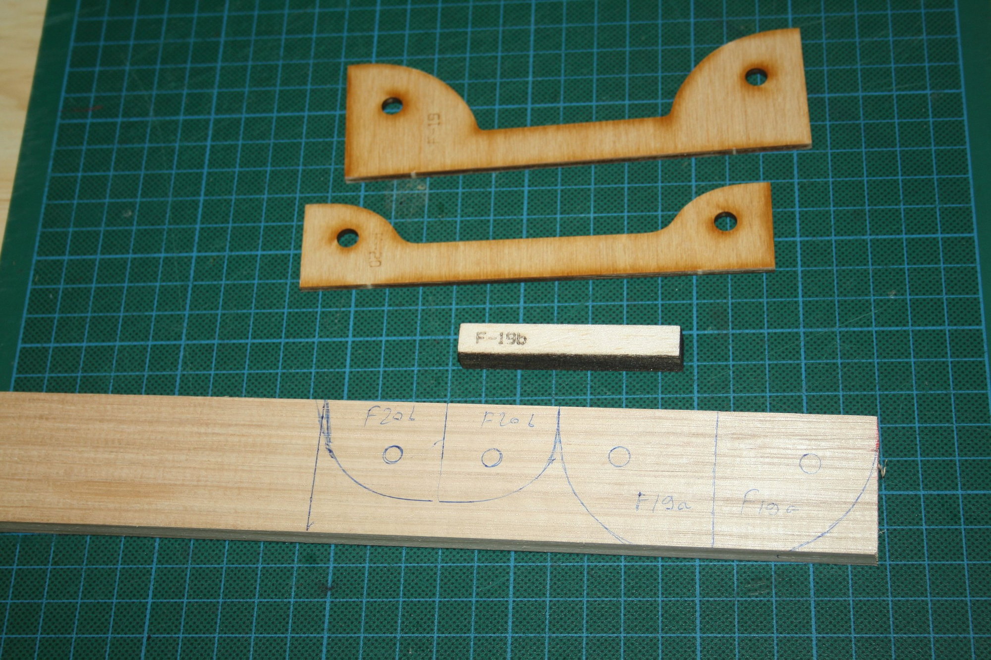
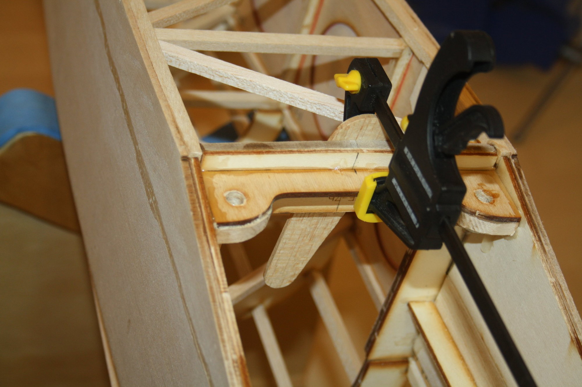
With the covering hopefully "secured" (I will believe that I got it when it is at my door, as Australian R/C shops are not the most reliable source of supply either), I got back to building, adding reinforcement F3b to the plywood wing retention bracket.
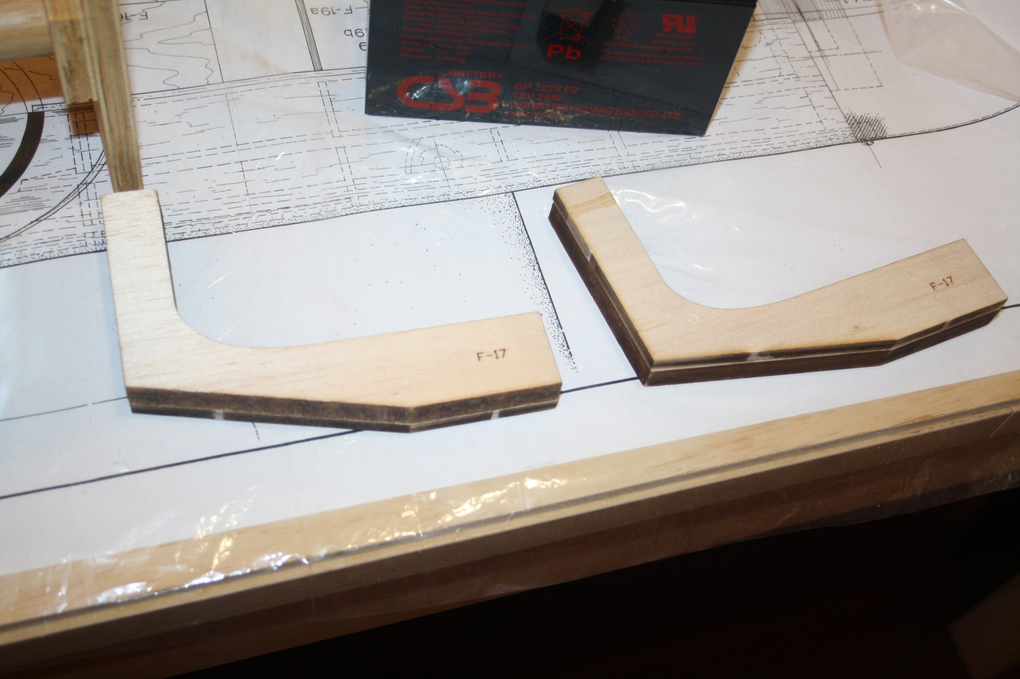
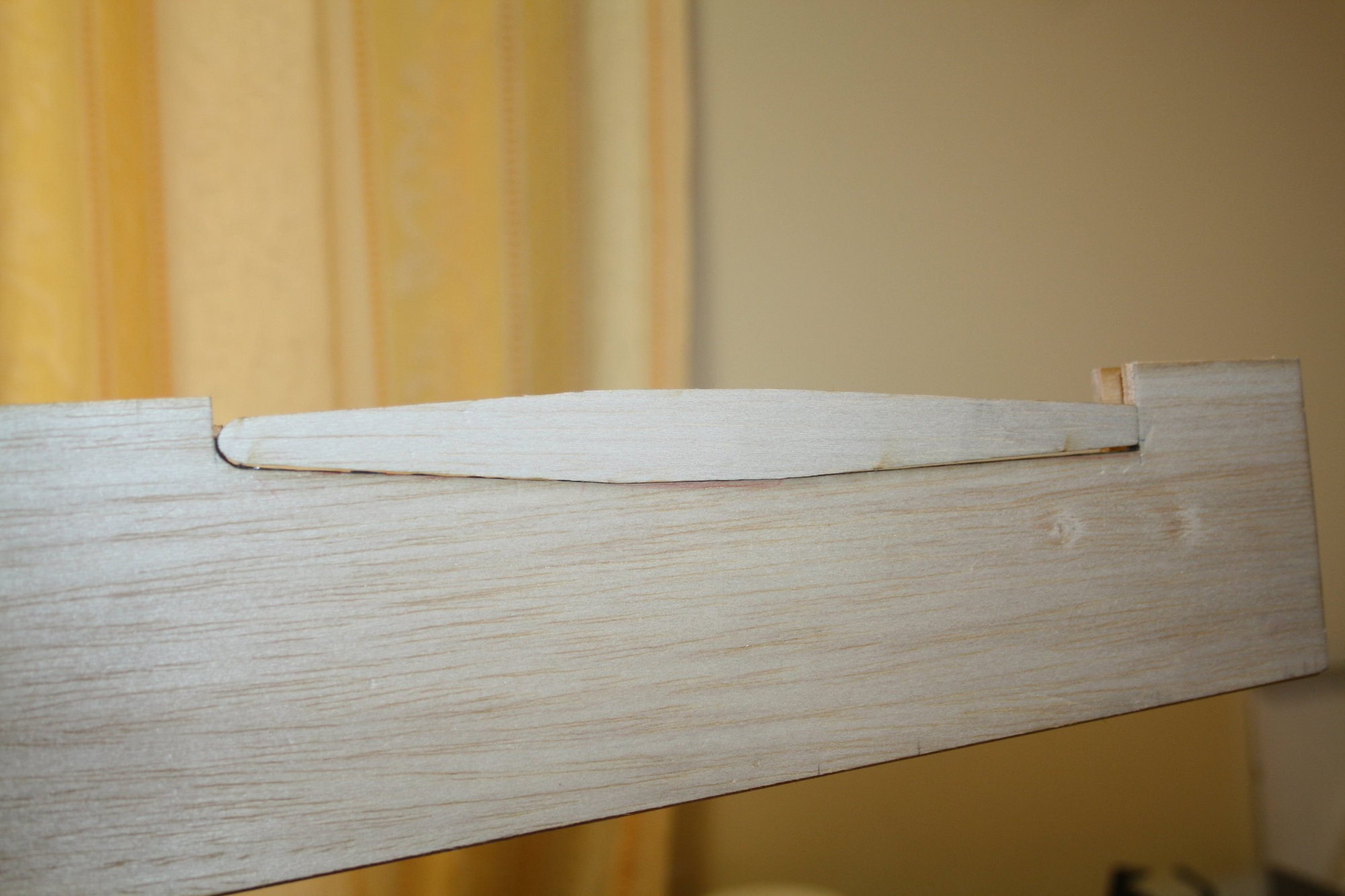
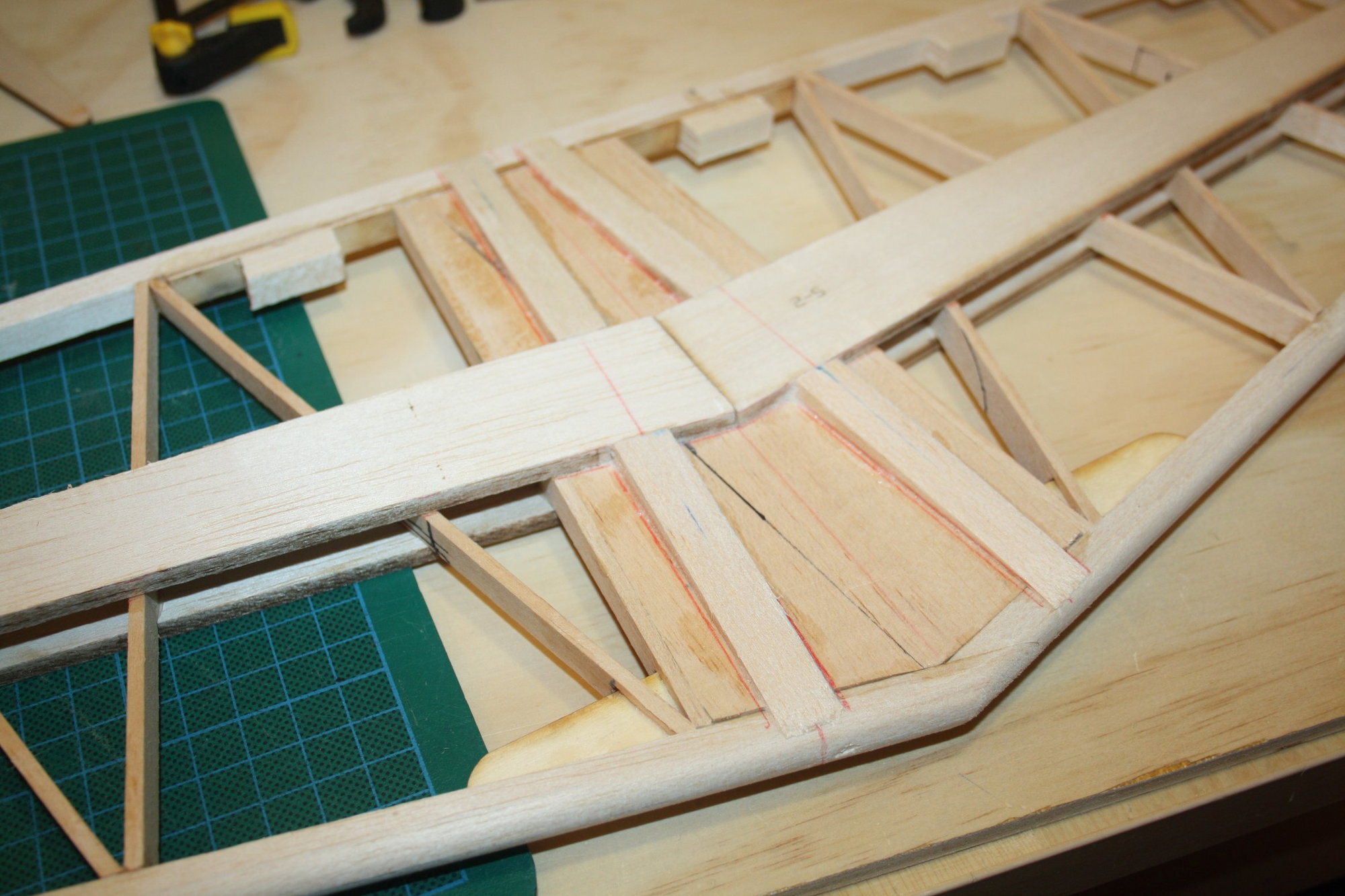
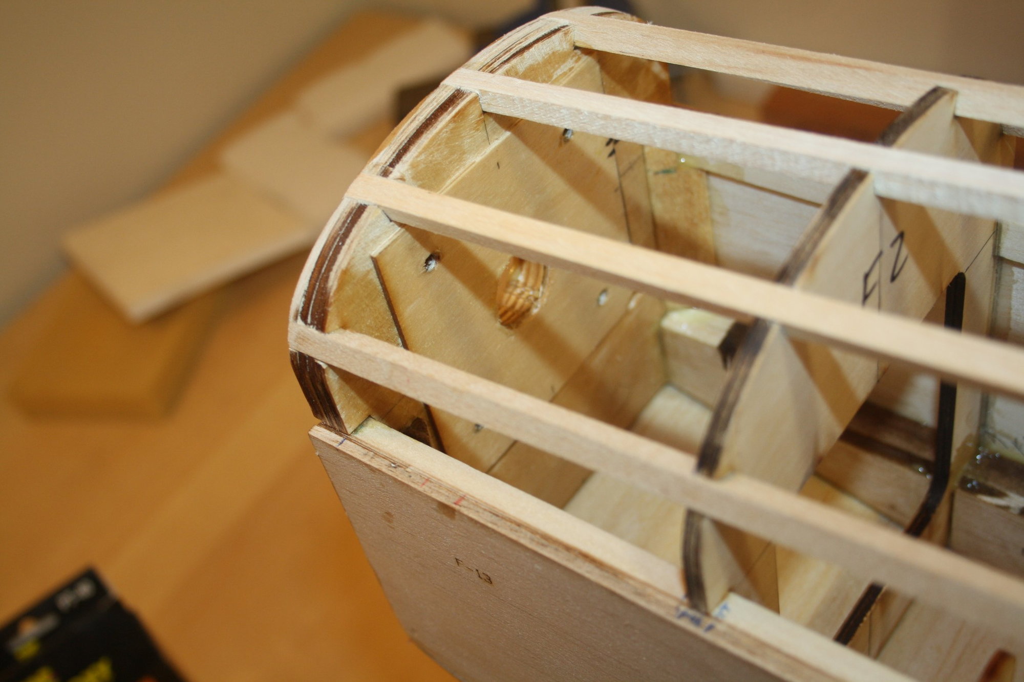
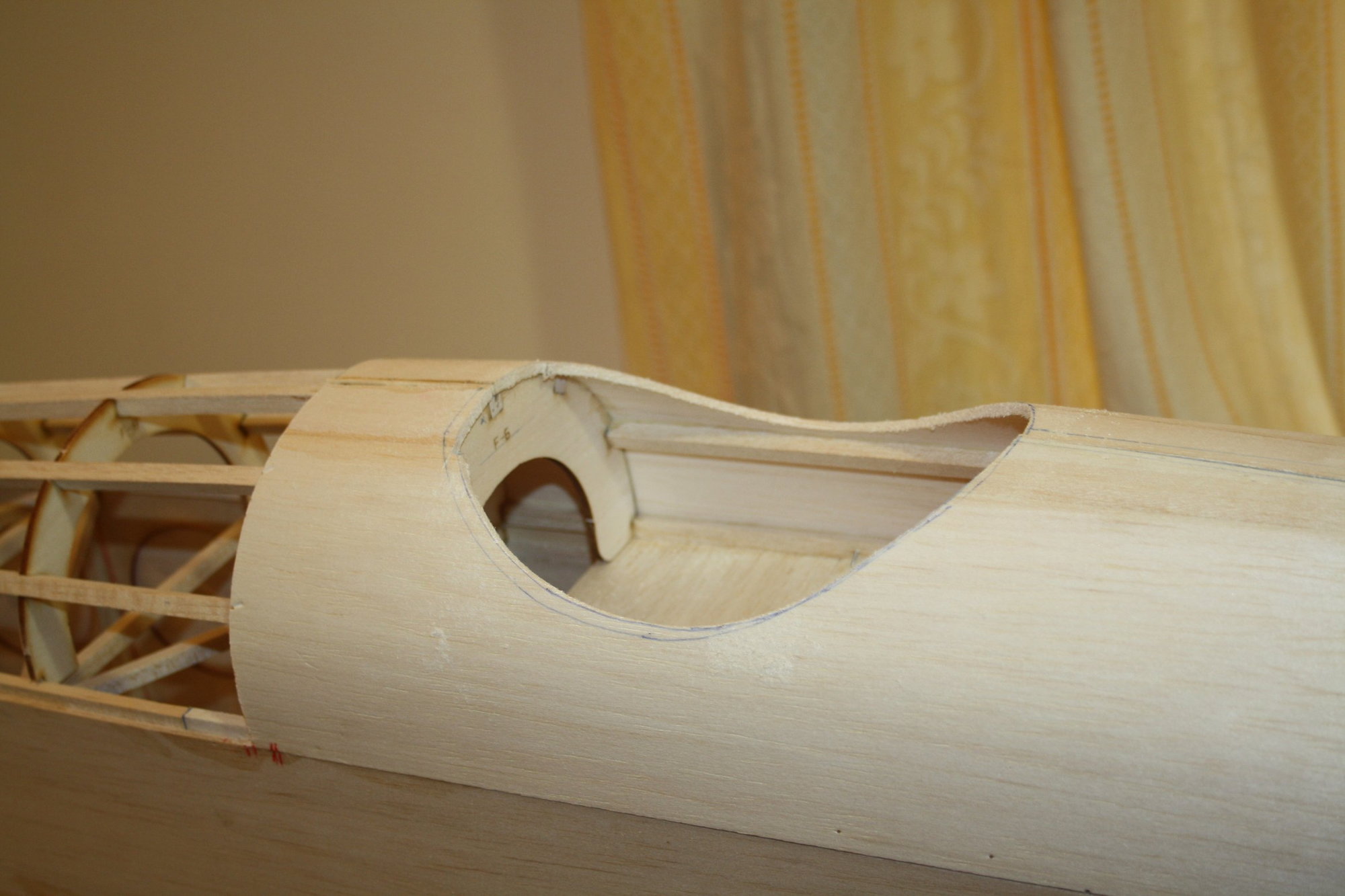
I was contemplating how I will attach the horizontal stabiliser to the fuselage as the centre section is open frame (where usually there is solid sheeting allowing for removal of covering and wood to wood glue joint). Even if I was to cover the horizontal stabiliser when attached to the fuselage, there will be an open-bay structure at the joint which is near impossible for me to cover while maintaining the correct shape.
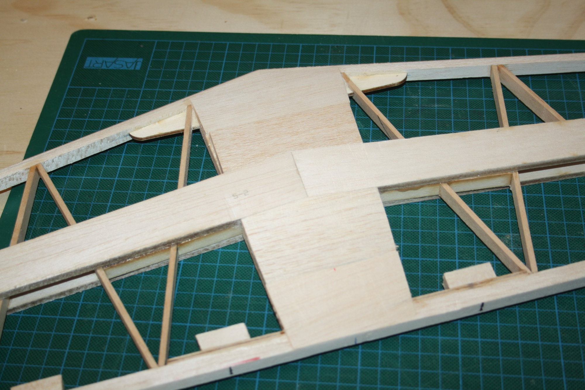
I used the cut-out from the original "hole" in the fuselage to draw corresponding triangles of thick balsa which will form the edge of the open bay for the covering to adhere to. After completing one side this way, I realised that I am wasting my time and made a solid centre section on the other side.

Cheers,
Eran
I just managed to sourced 5 rolls of Monokote for my primary colour in Australia for $48AUD each (Ouch!). The reason I needed the covering now is that I prefer covering prior to installing major components.
With the covering hopefully "secured" (I will believe that I got it when it is at my door, as Australian R/C shops are not the most reliable source of supply either), I got back to building, adding reinforcement F3b to the plywood wing retention bracket.
I was contemplating how I will attach the horizontal stabiliser to the fuselage as the centre section is open frame (where usually there is solid sheeting allowing for removal of covering and wood to wood glue joint). Even if I was to cover the horizontal stabiliser when attached to the fuselage, there will be an open-bay structure at the joint which is near impossible for me to cover while maintaining the correct shape.
I used the cut-out from the original "hole" in the fuselage to draw corresponding triangles of thick balsa which will form the edge of the open bay for the covering to adhere to. After completing one side this way, I realised that I am wasting my time and made a solid centre section on the other side.
Cheers,
Eran
12-08-2020, 10:00 PM
#118
Thread Starter
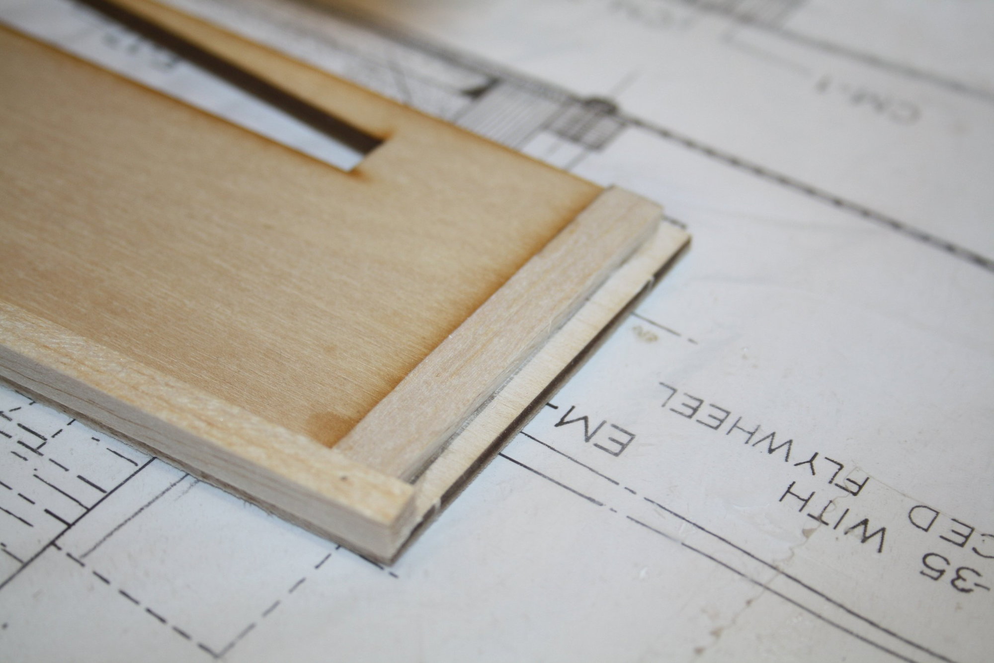
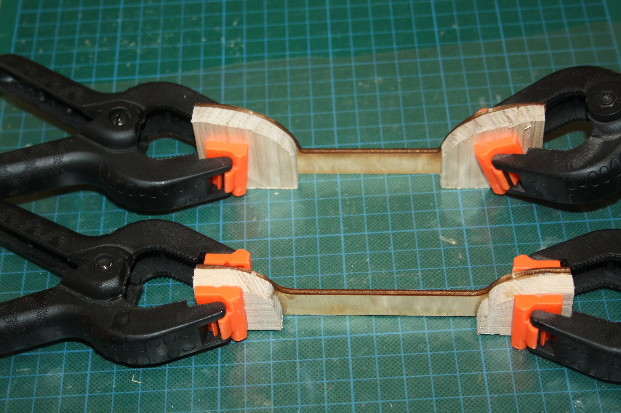
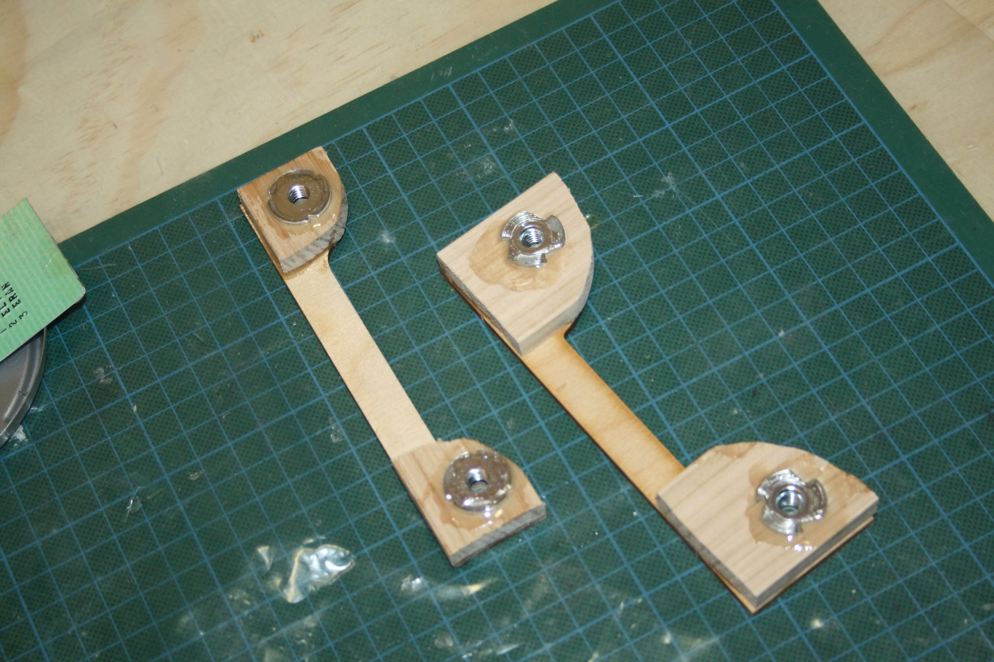
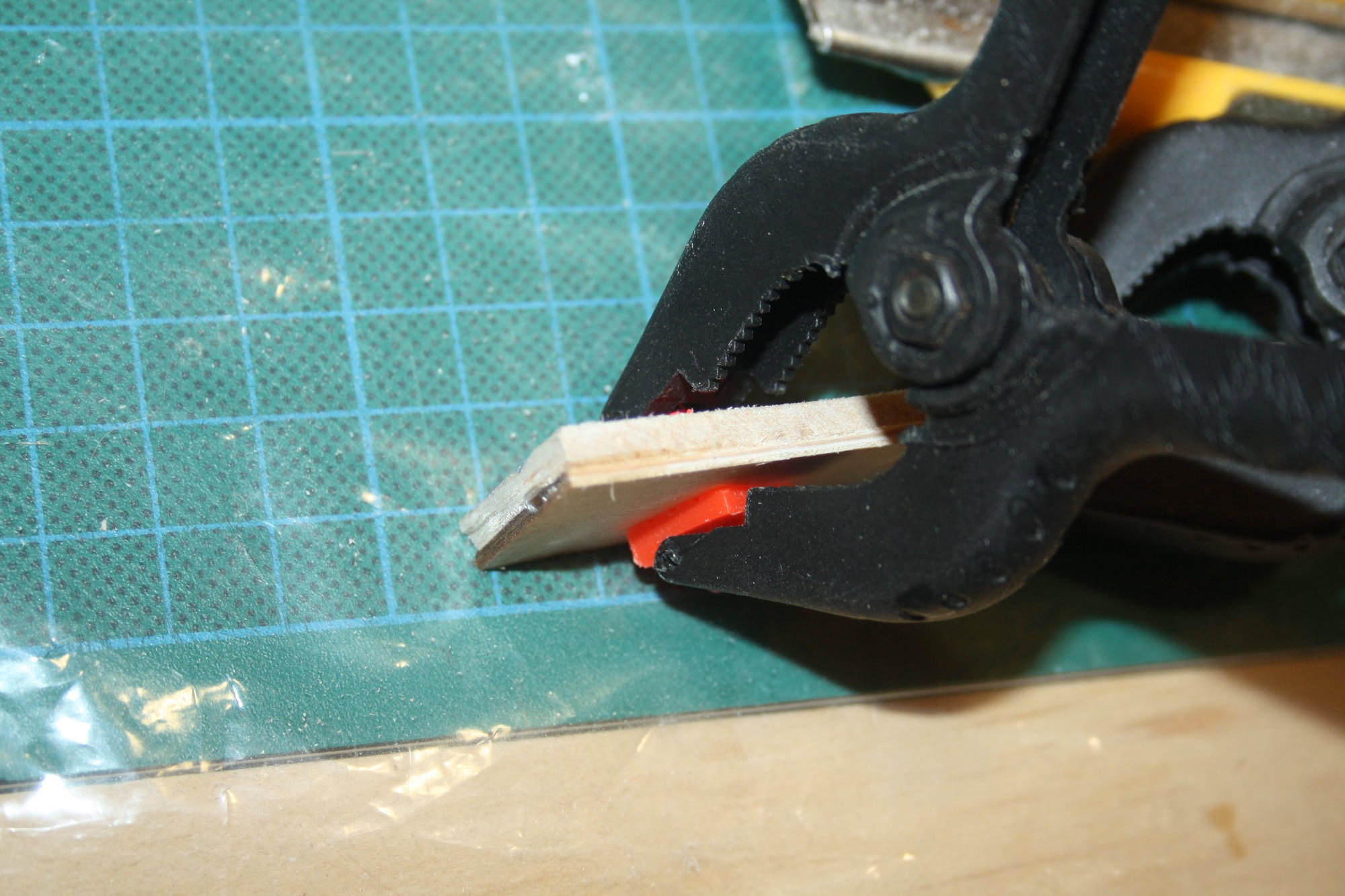
I made "brackets" from a sandwich of thin plywood and balsa to be used as a mounting / glue contact area for the horizontal stabiliser.
I then used the opportunity that I still have easy access, and fuel proofed the fuel tank bay and the back of the firewall with Epoxy finishing resin.
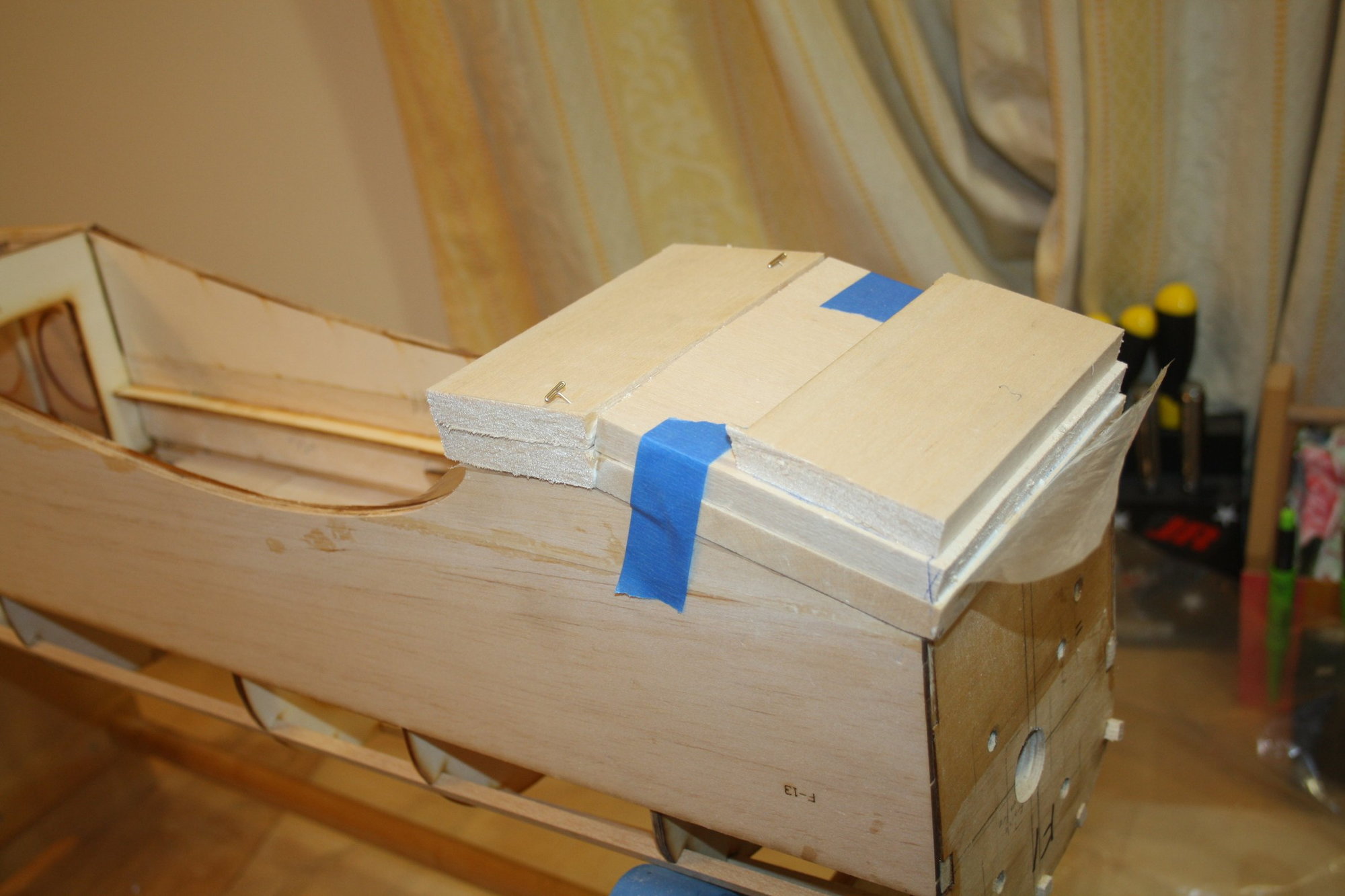
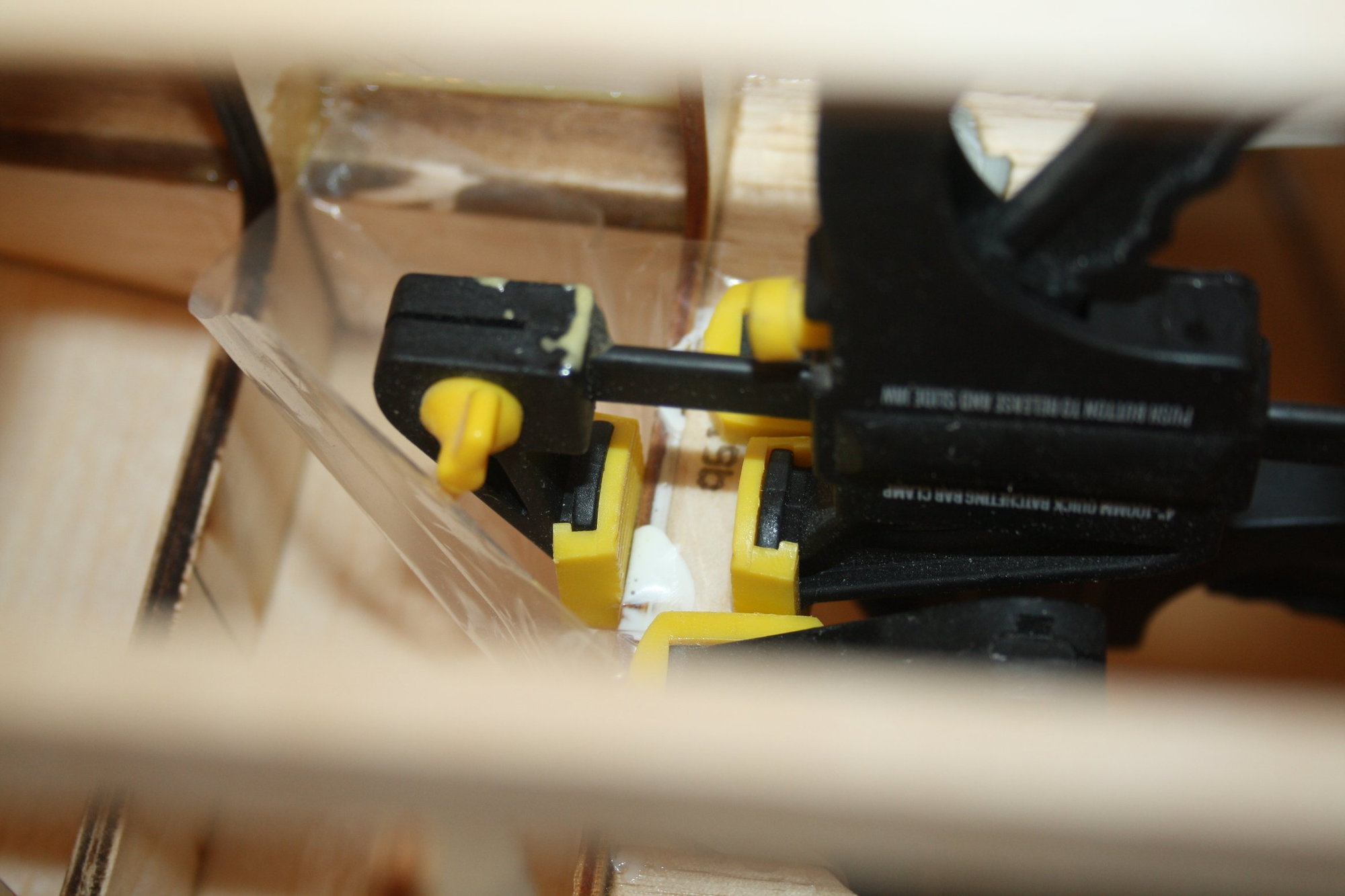
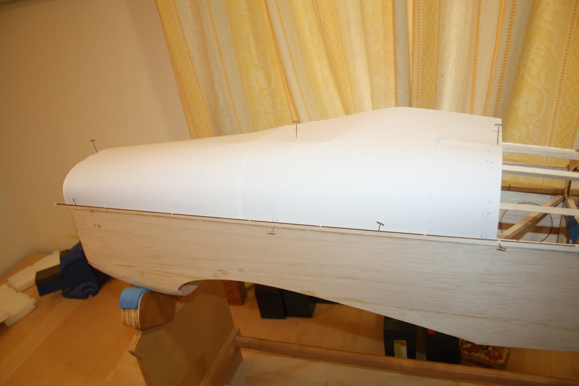
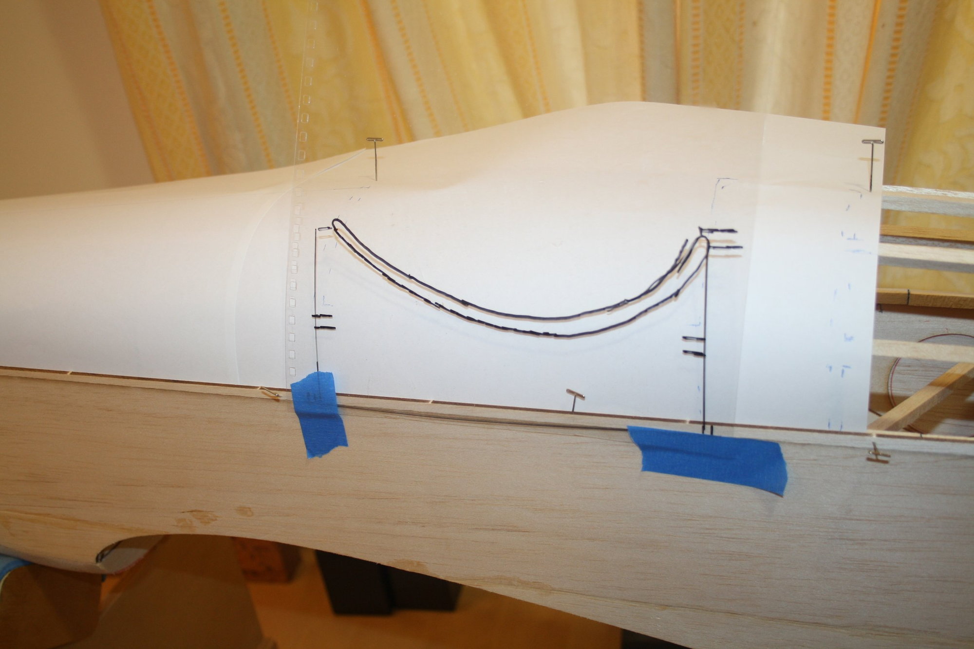
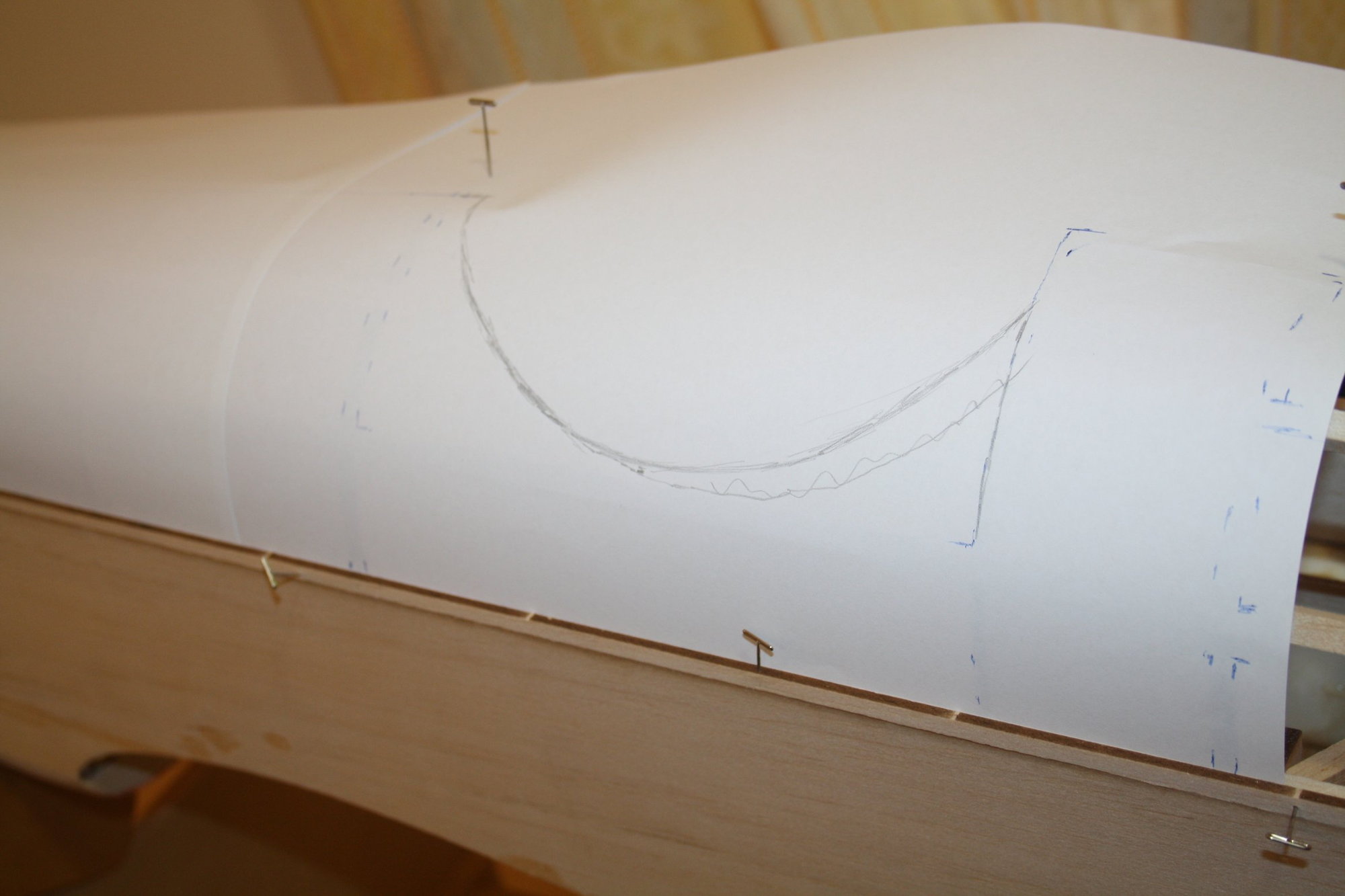
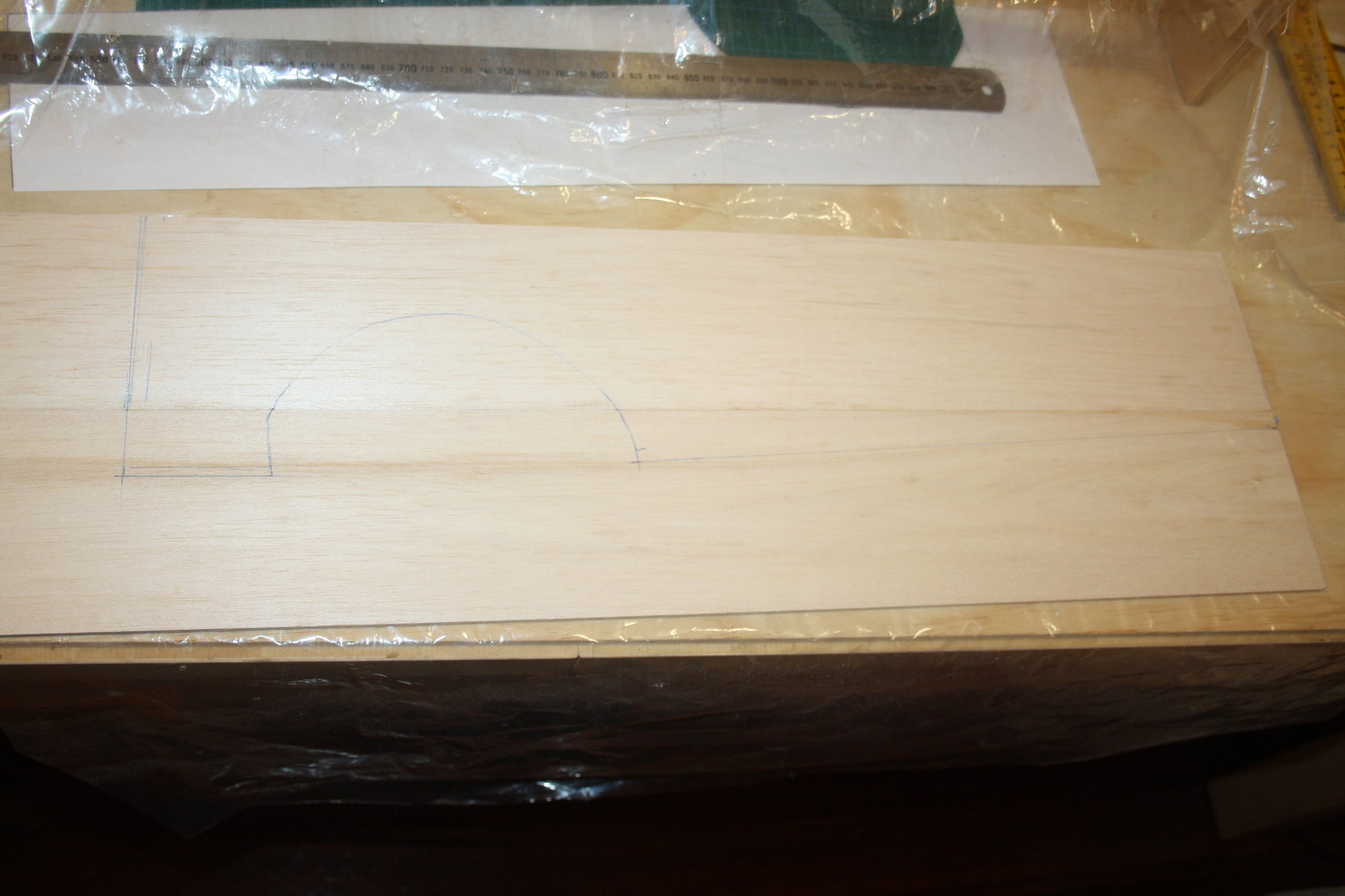
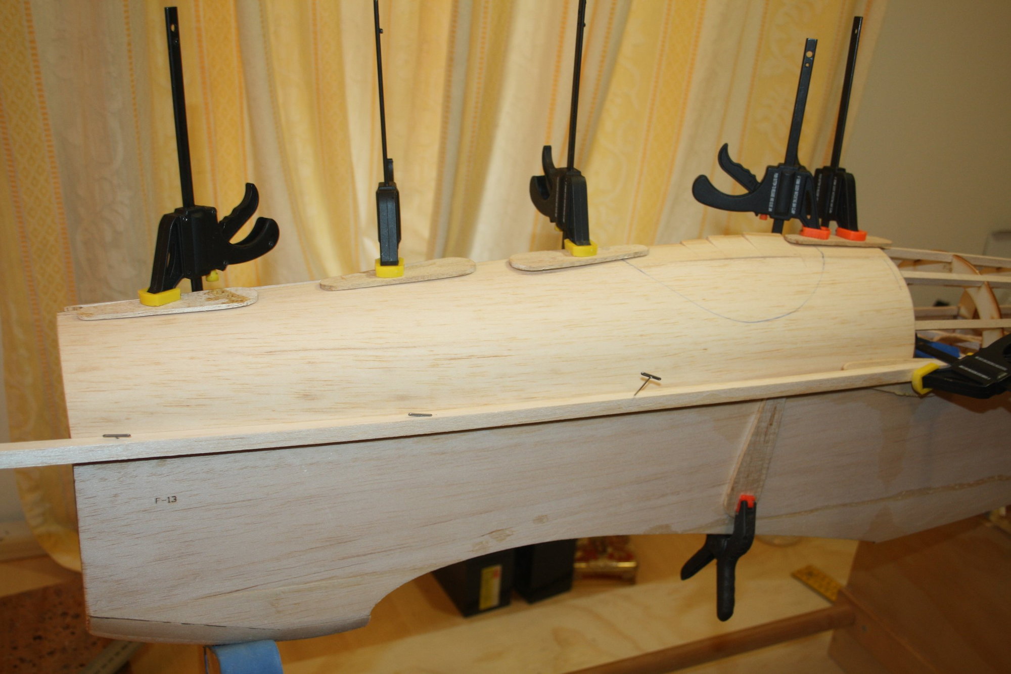
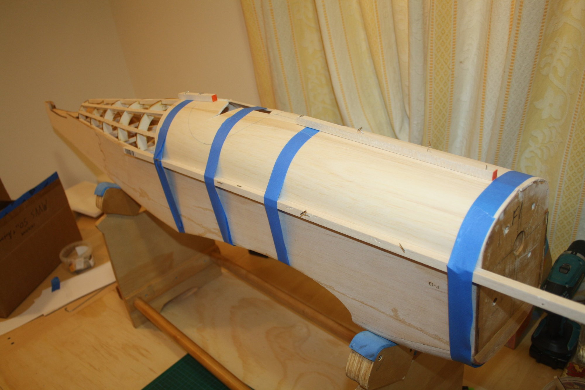
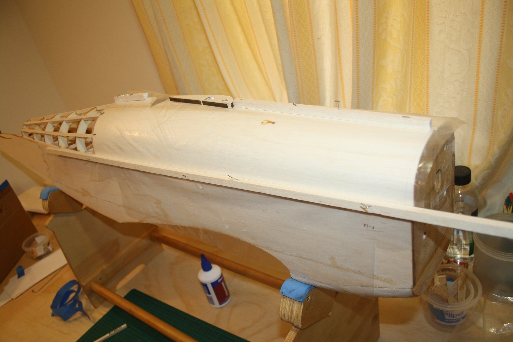
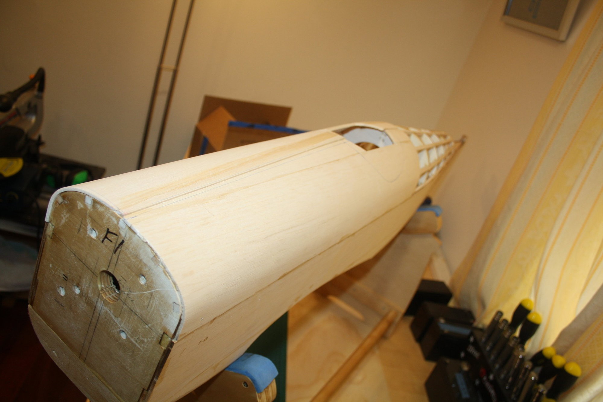
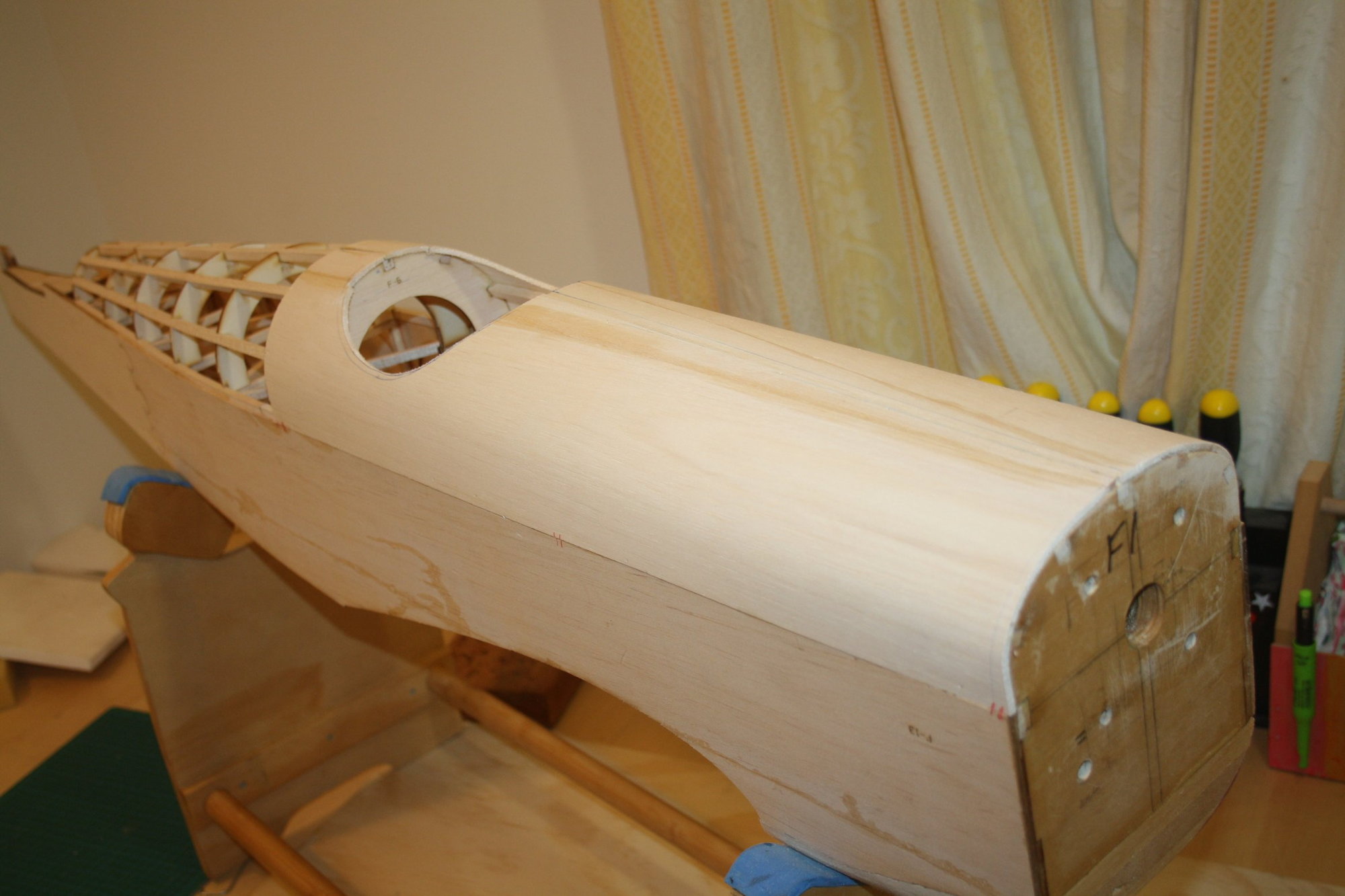
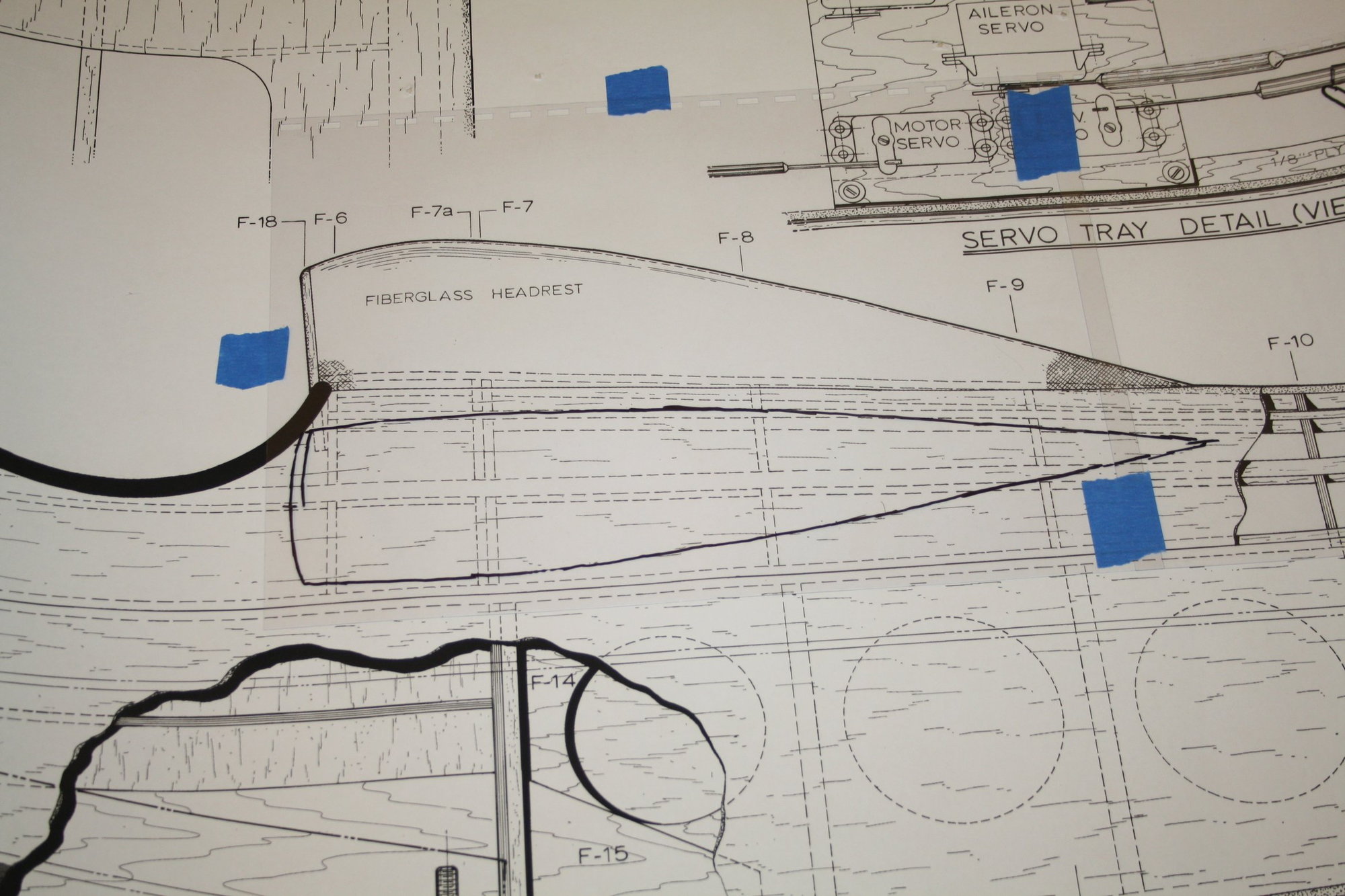
With this done, I CAD ("Cardboard" Aided Design) the top forward sheeting from the firewall to behind the cockpit (F8). I then joined a couple of 3mm balsa sheets into which I traced the CAD drawing. I softened the balsa with warm water and formed it to shape over the structure, where it is now drying.
Cheers,
Eran
I then used the opportunity that I still have easy access, and fuel proofed the fuel tank bay and the back of the firewall with Epoxy finishing resin.
With this done, I CAD ("Cardboard" Aided Design) the top forward sheeting from the firewall to behind the cockpit (F8). I then joined a couple of 3mm balsa sheets into which I traced the CAD drawing. I softened the balsa with warm water and formed it to shape over the structure, where it is now drying.
Cheers,
Eran
The following users liked this post:
Richard-V (12-10-2020)


 12-18-2020, 08:43 PM
#122
Thread Starter
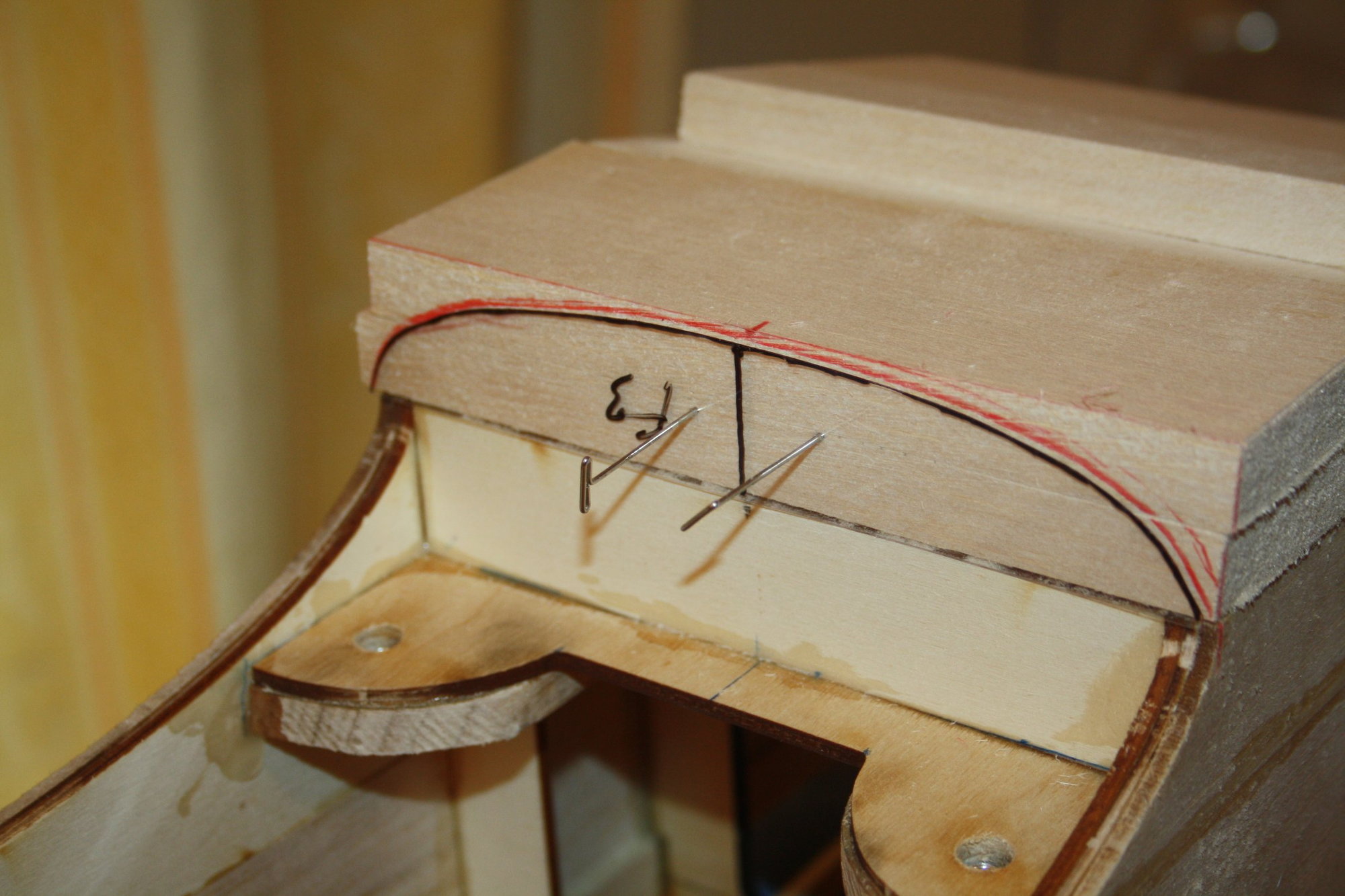
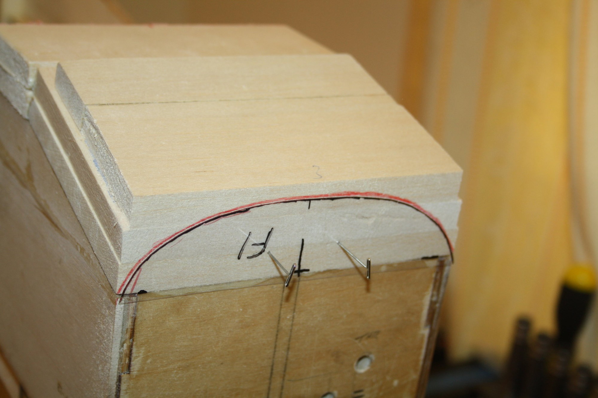
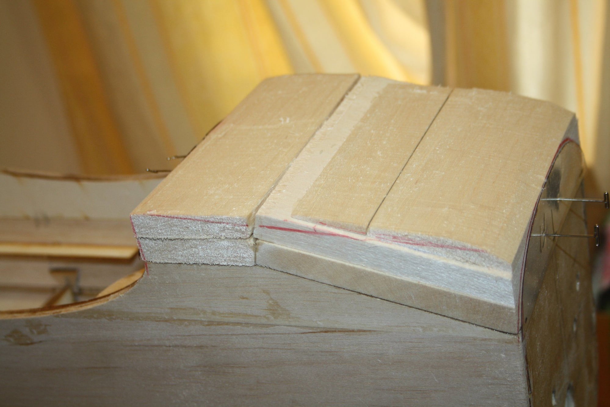
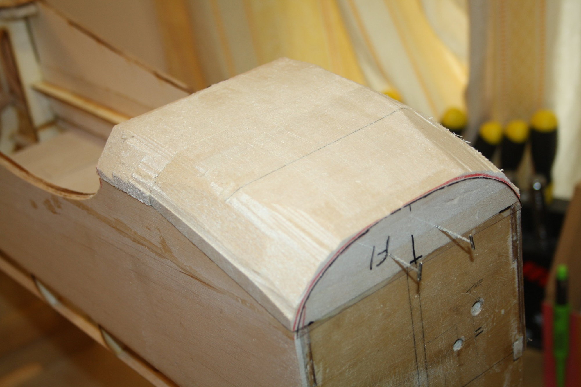
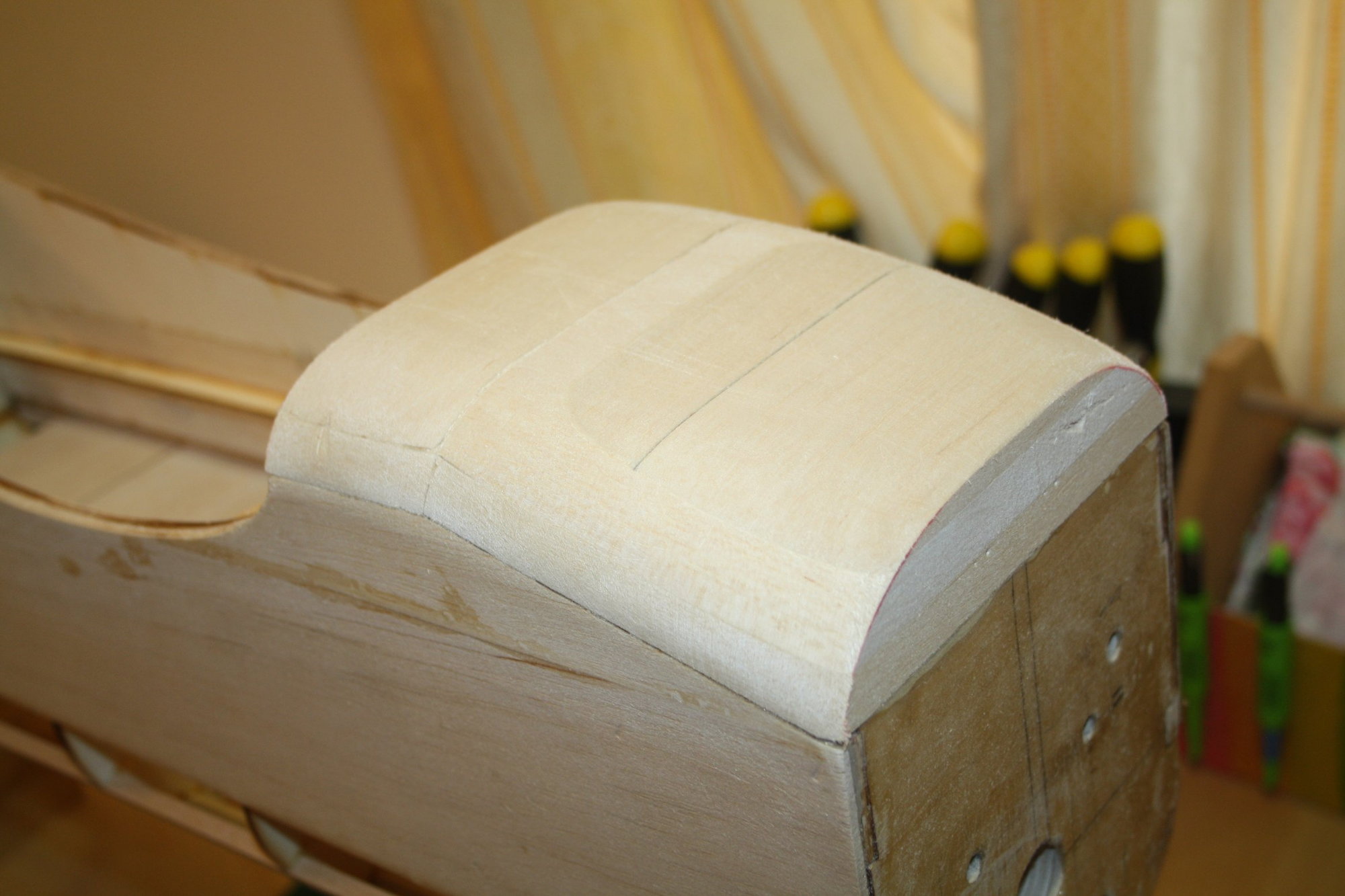
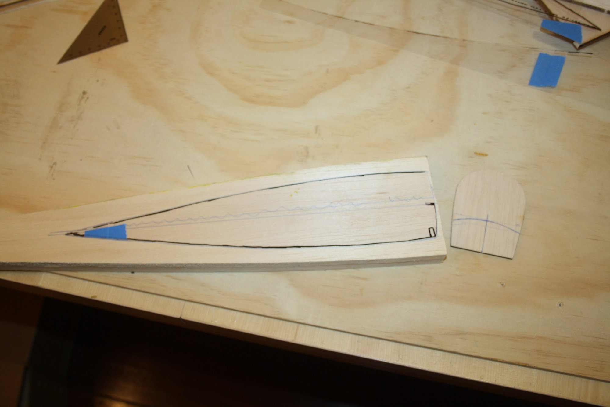
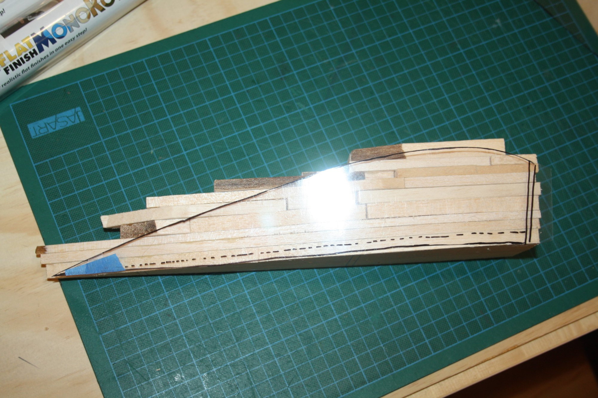
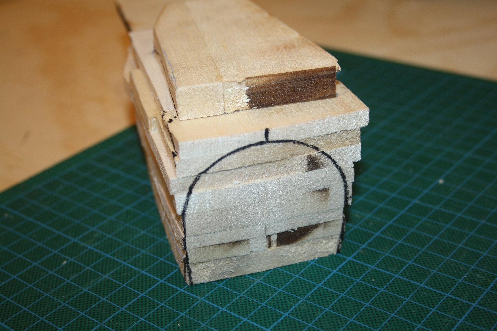
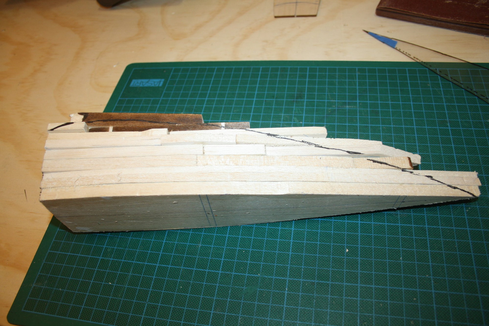
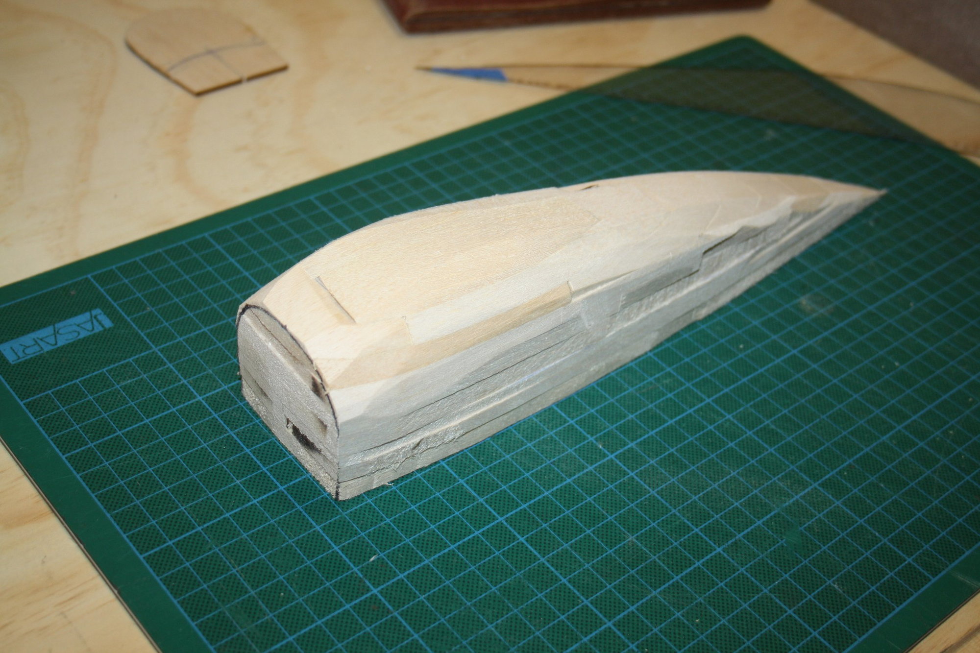
I got to a stage where I want to cover the horizontal stabiliser before I progress further. While waiting for the Monokote to arrive, I started making the pile of balsa scraps required for my attempt to shape the pilot headrest. This headrest is surprisingly large and took a lot of scraps of balsa to make the "block" (the starting point for sanding)...
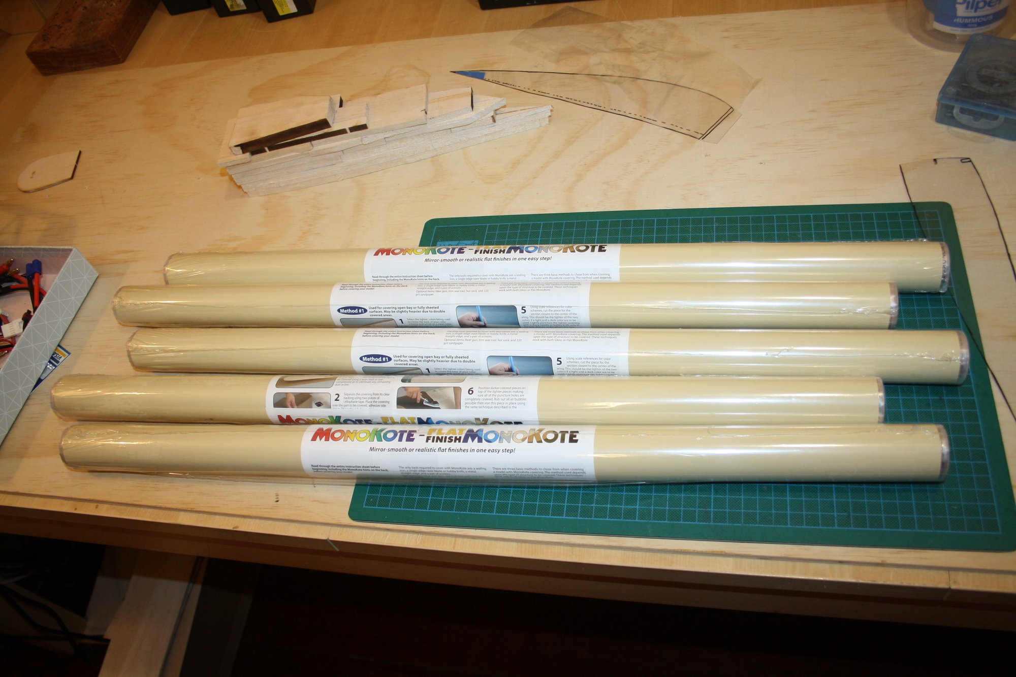
Then today, the knock on the door from the Post office delivery man and my main colour Monokote has finally arrived. Originally I planned to cover the whole aeroplane in cream with trim in dark blue (Monokote flat Insignia Blue). However, the plan changed and the fuselage main colour will be dark blue if I can source the required amount of Monokote (all other surfaces stay in cream). I managed to purchase one roll of flat insignia blue so far, so this plan is subject to changes...
Cheers,
Eran
12-20-2020, 10:37 PM
#123
Thread Starter
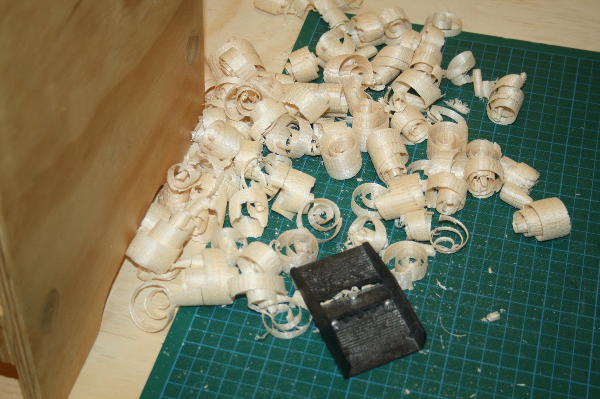
I used the belt / disk sander for the preliminary shaping of the headrest.
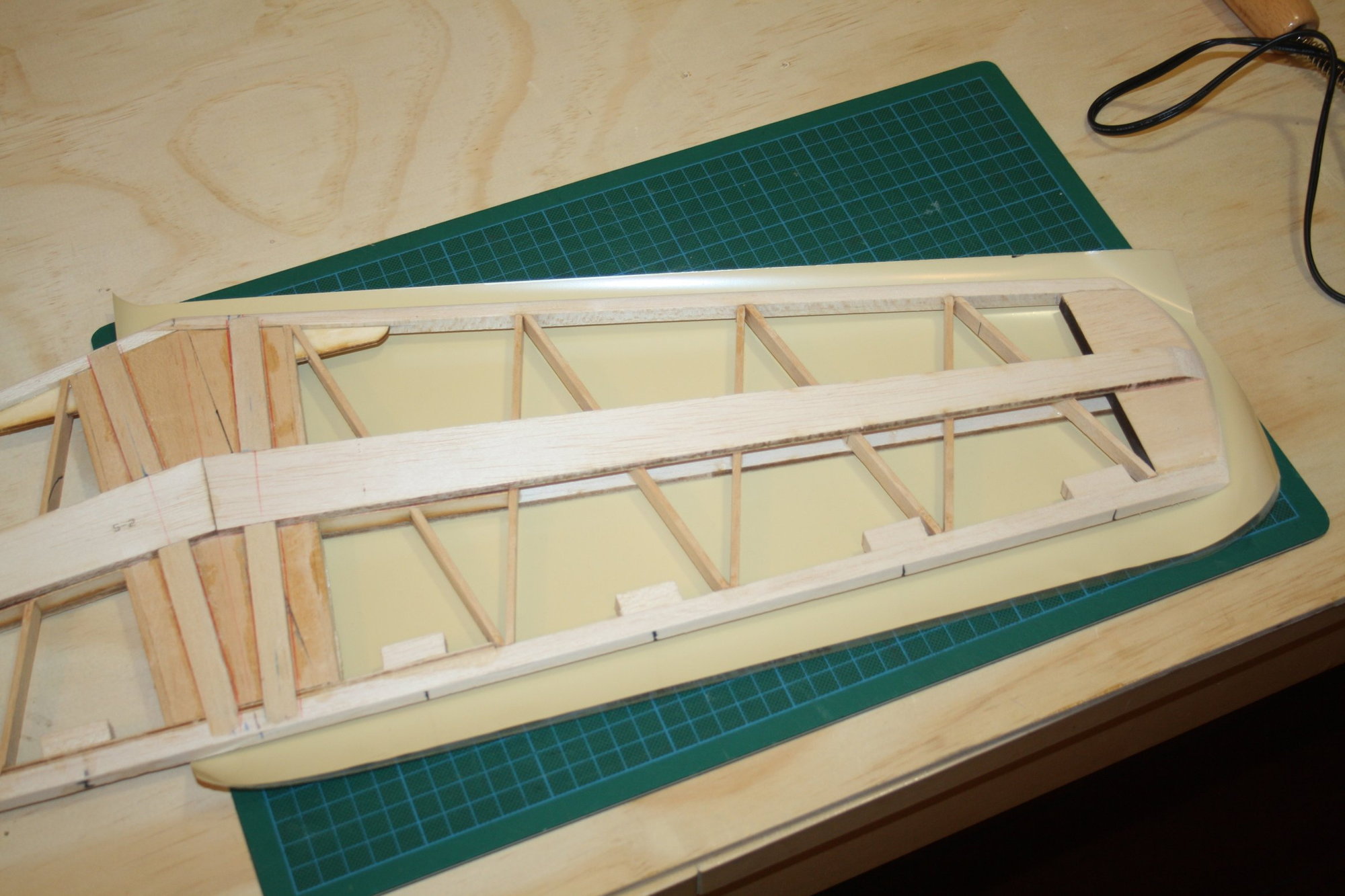
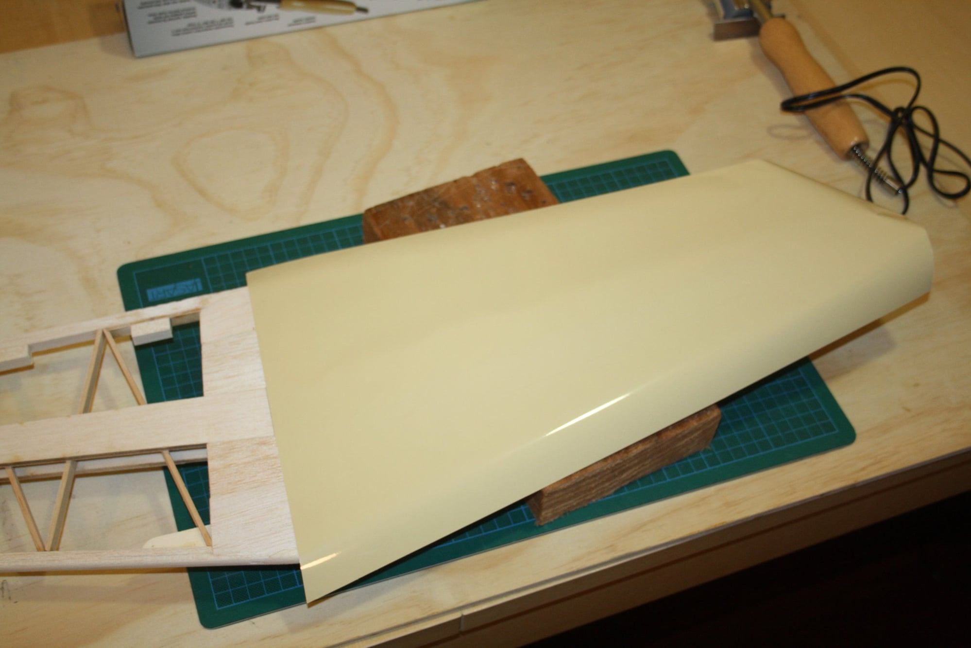
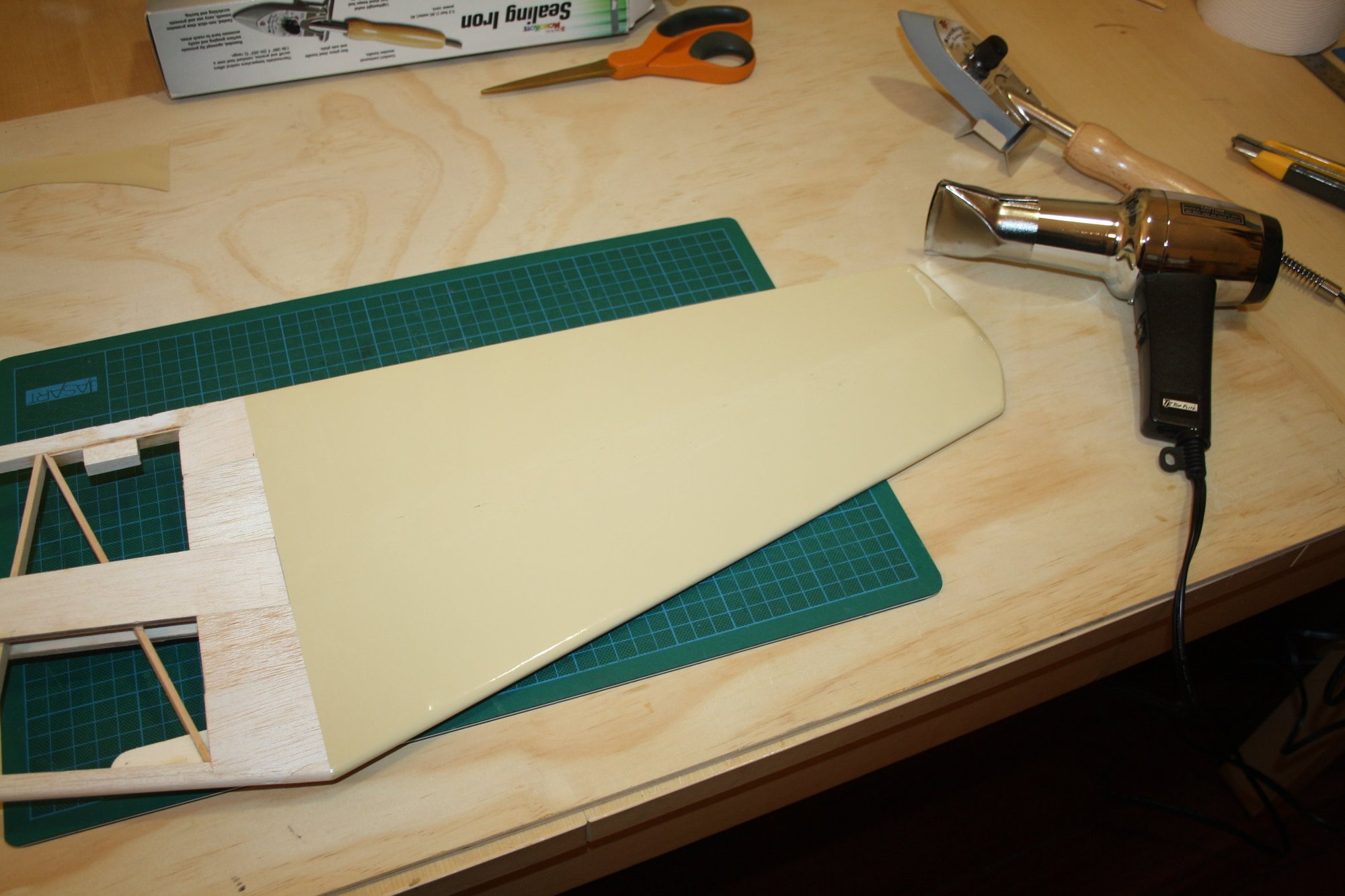
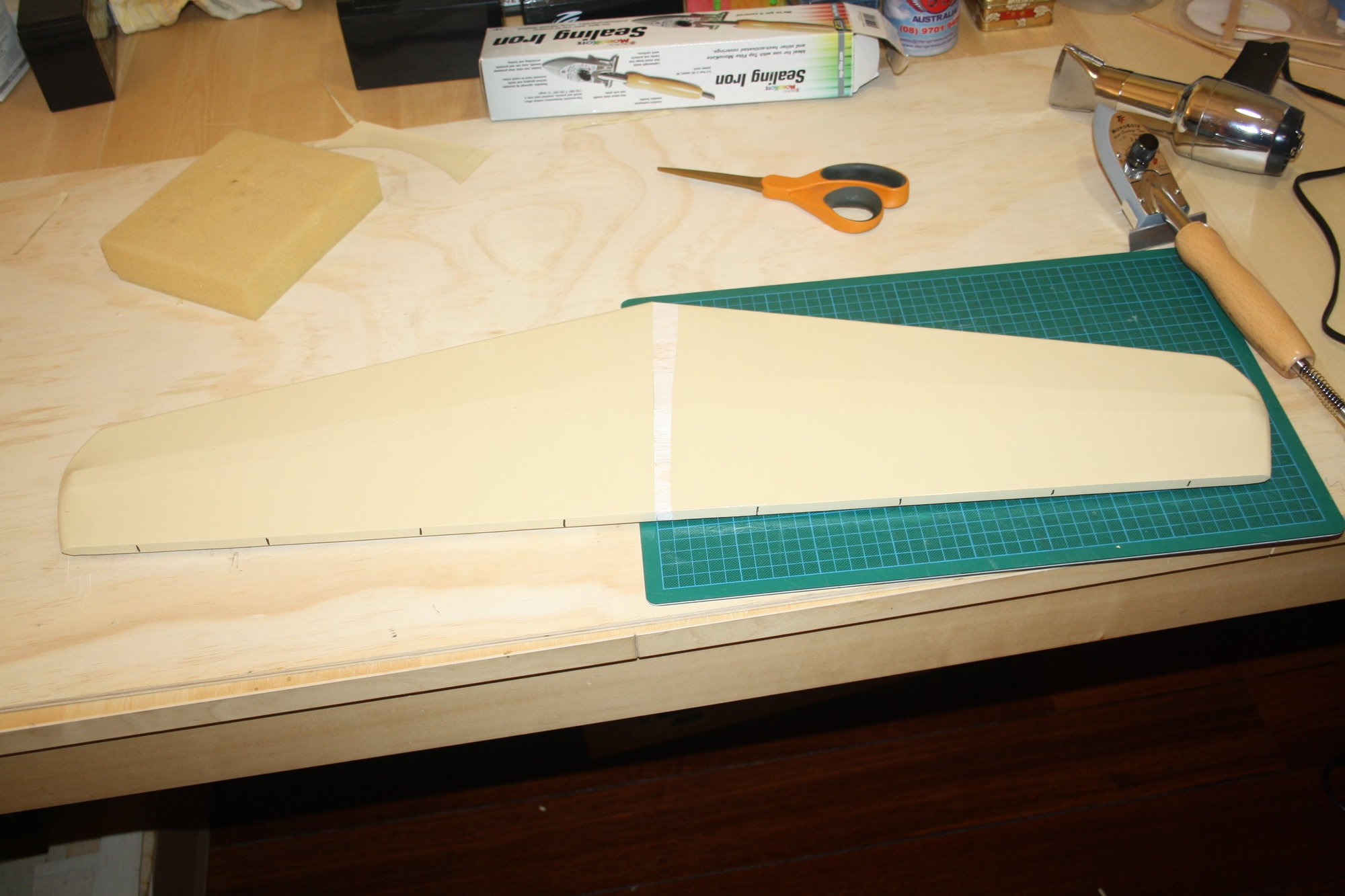
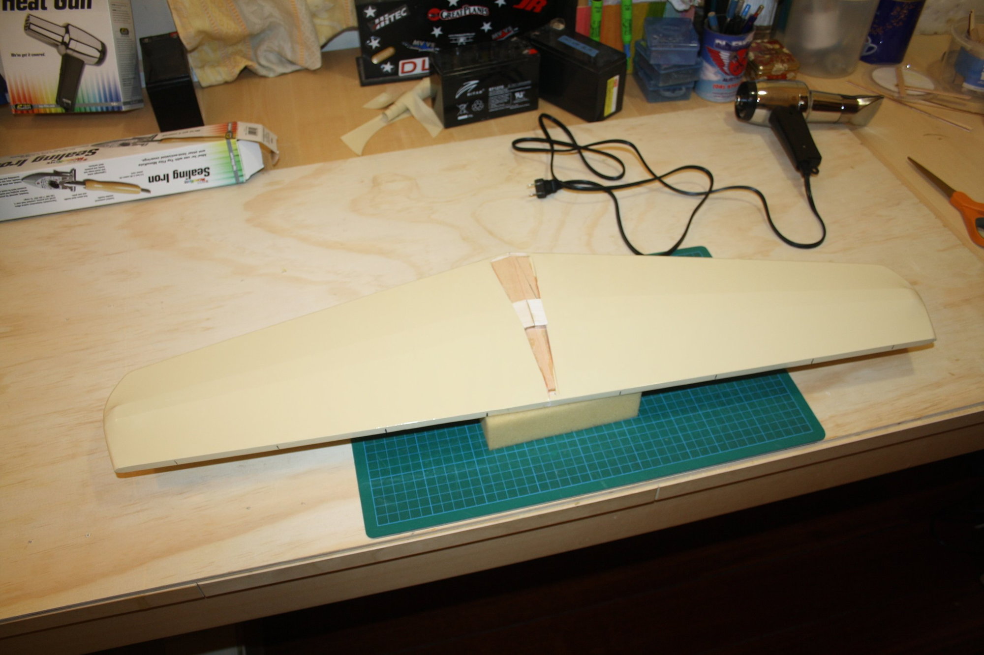
I then covered the horizontal Stabiliser and I am reasonably pleased with the result. What a great covering material is Monokote.

Cheers,
Eran
I then covered the horizontal Stabiliser and I am reasonably pleased with the result. What a great covering material is Monokote.
Cheers,
Eran
12-24-2020, 12:59 AM
#125
Thread Starter
Bob - Thank you.
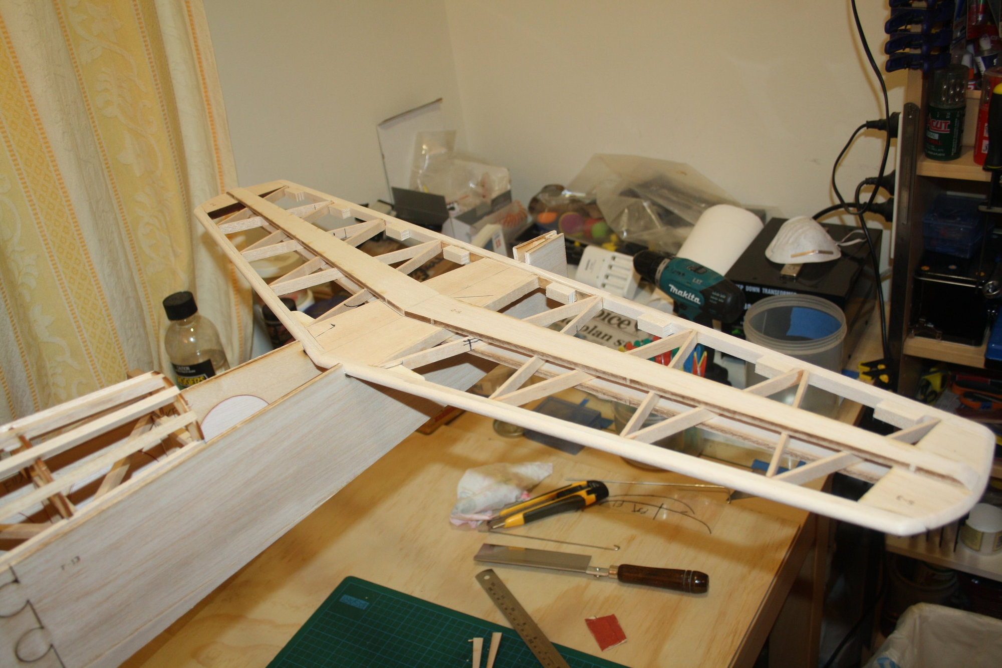
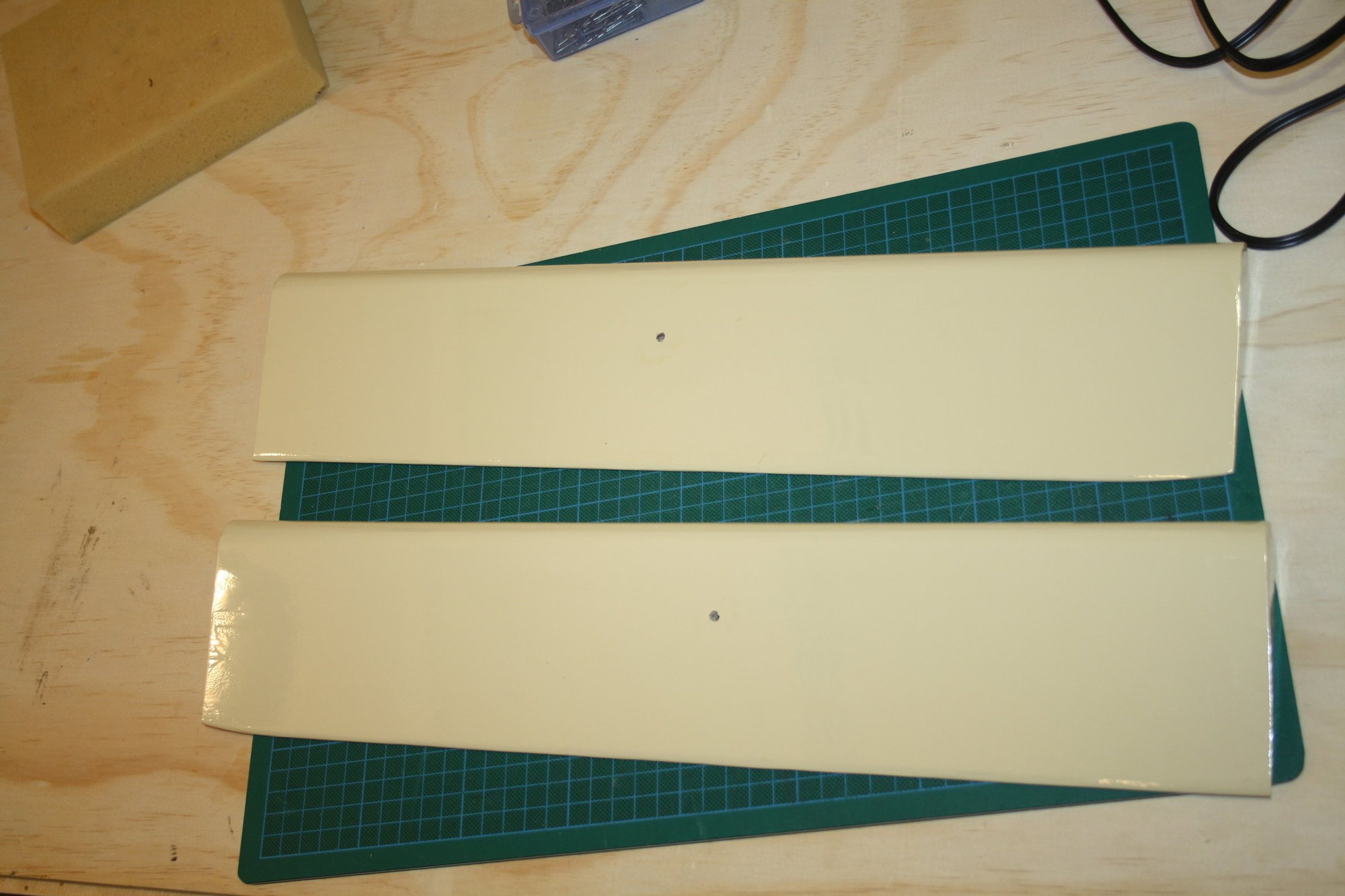
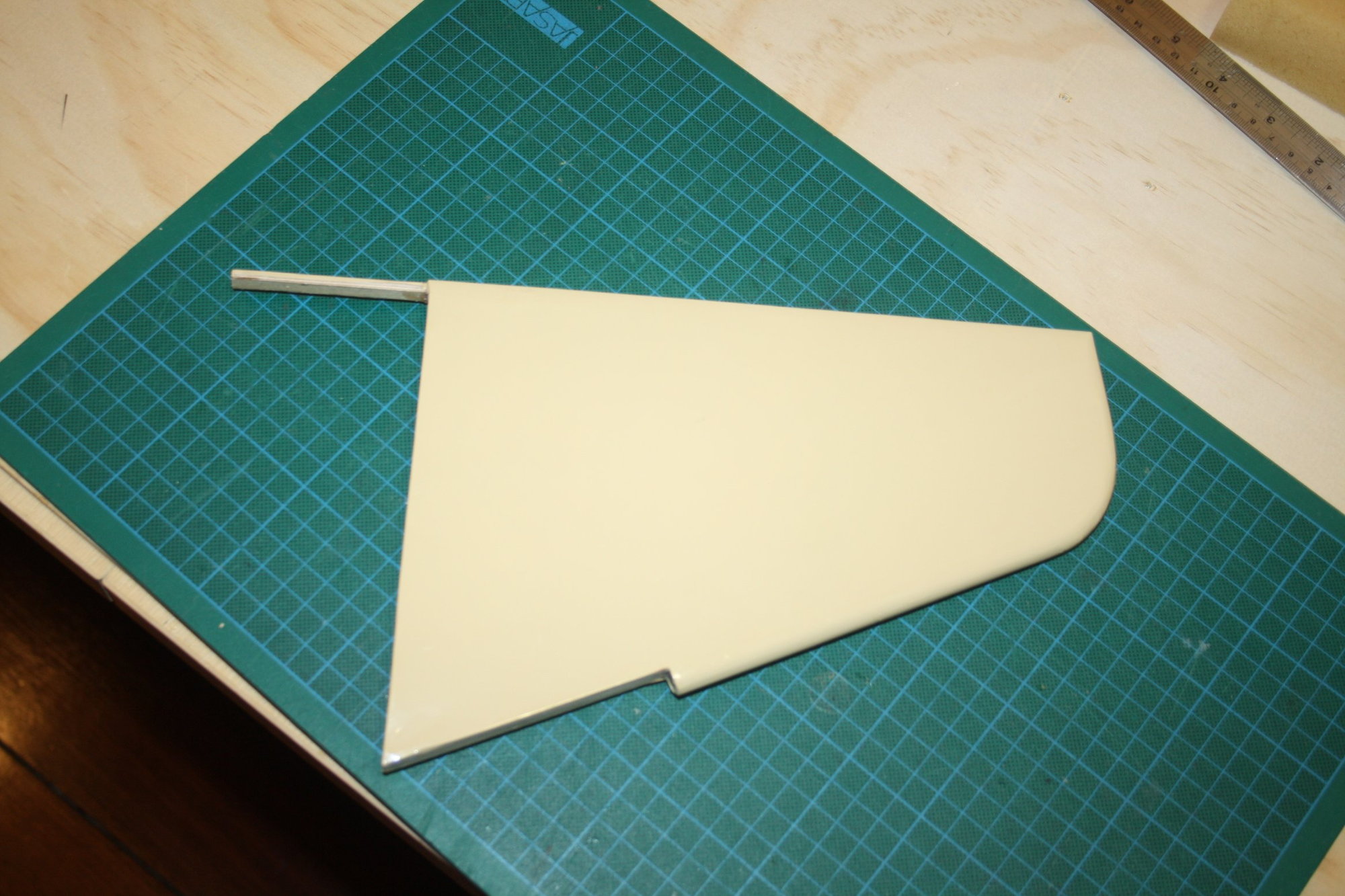
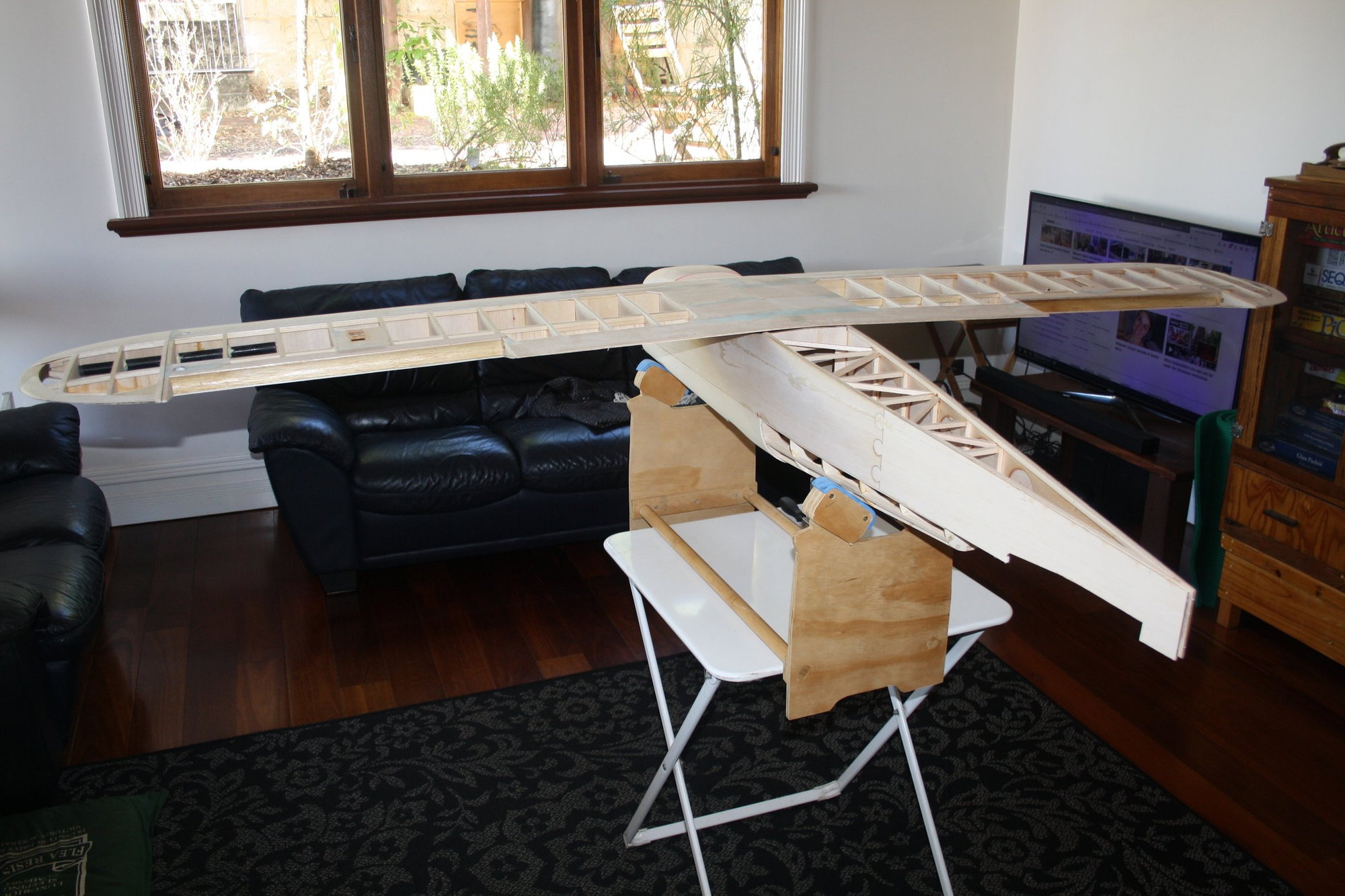
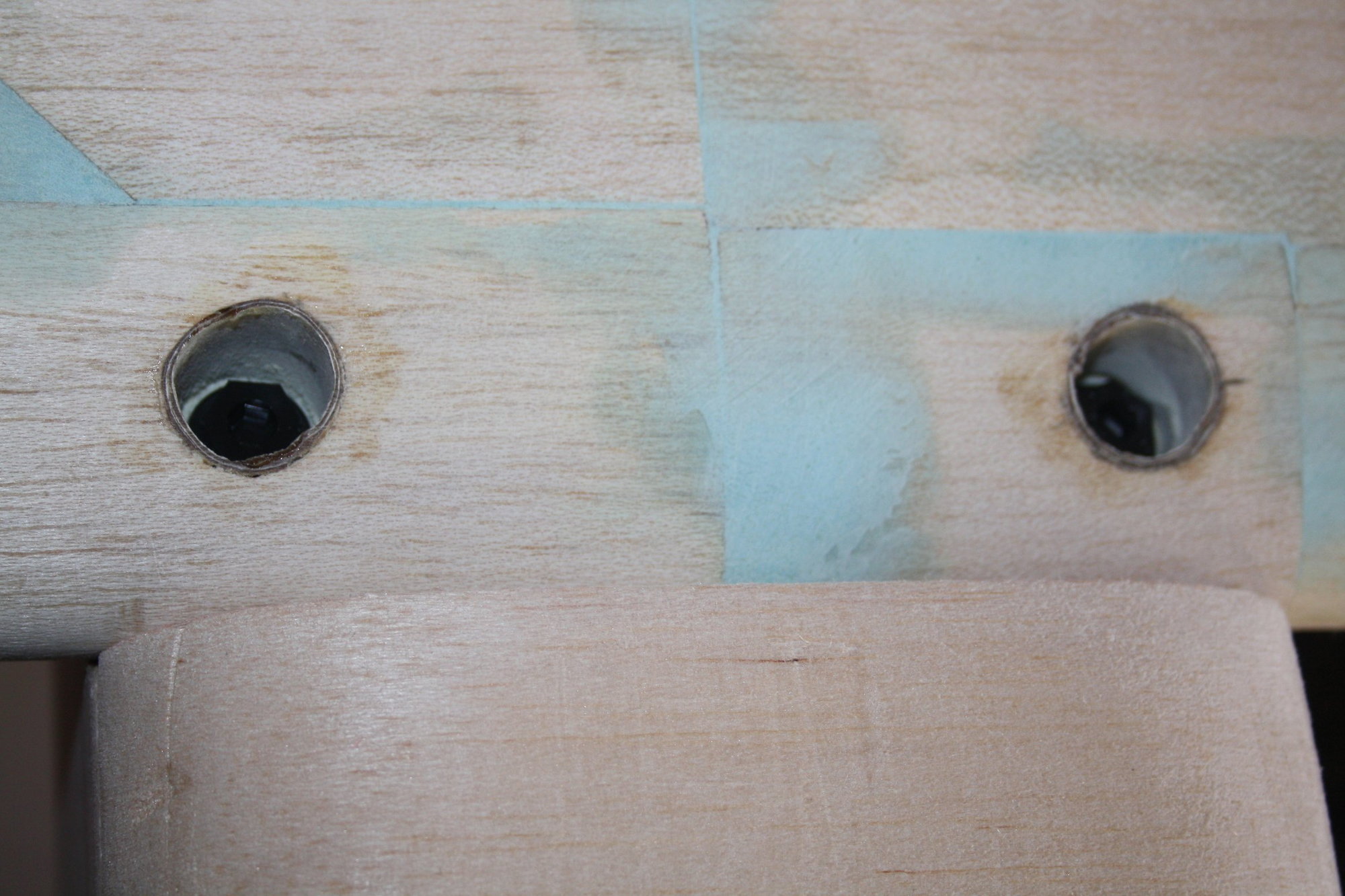
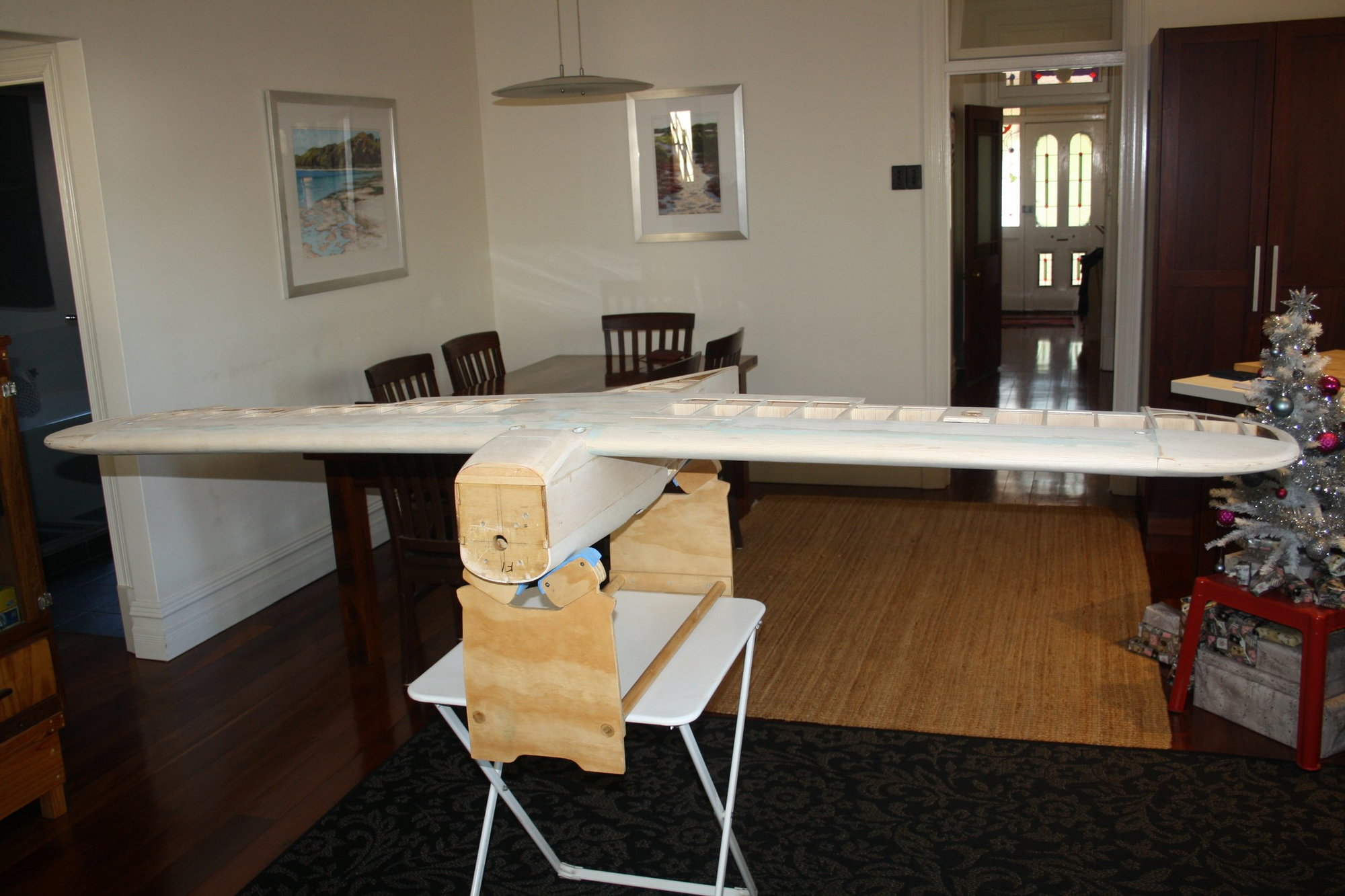
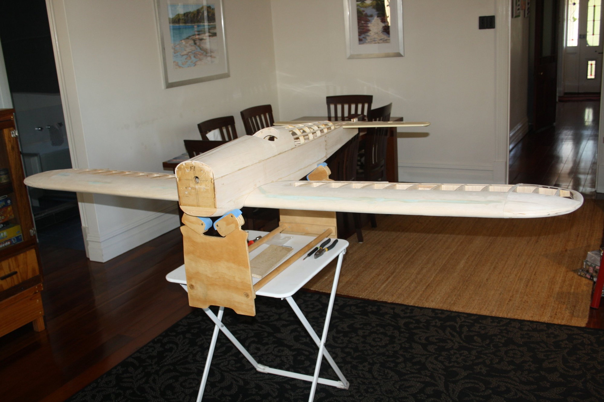
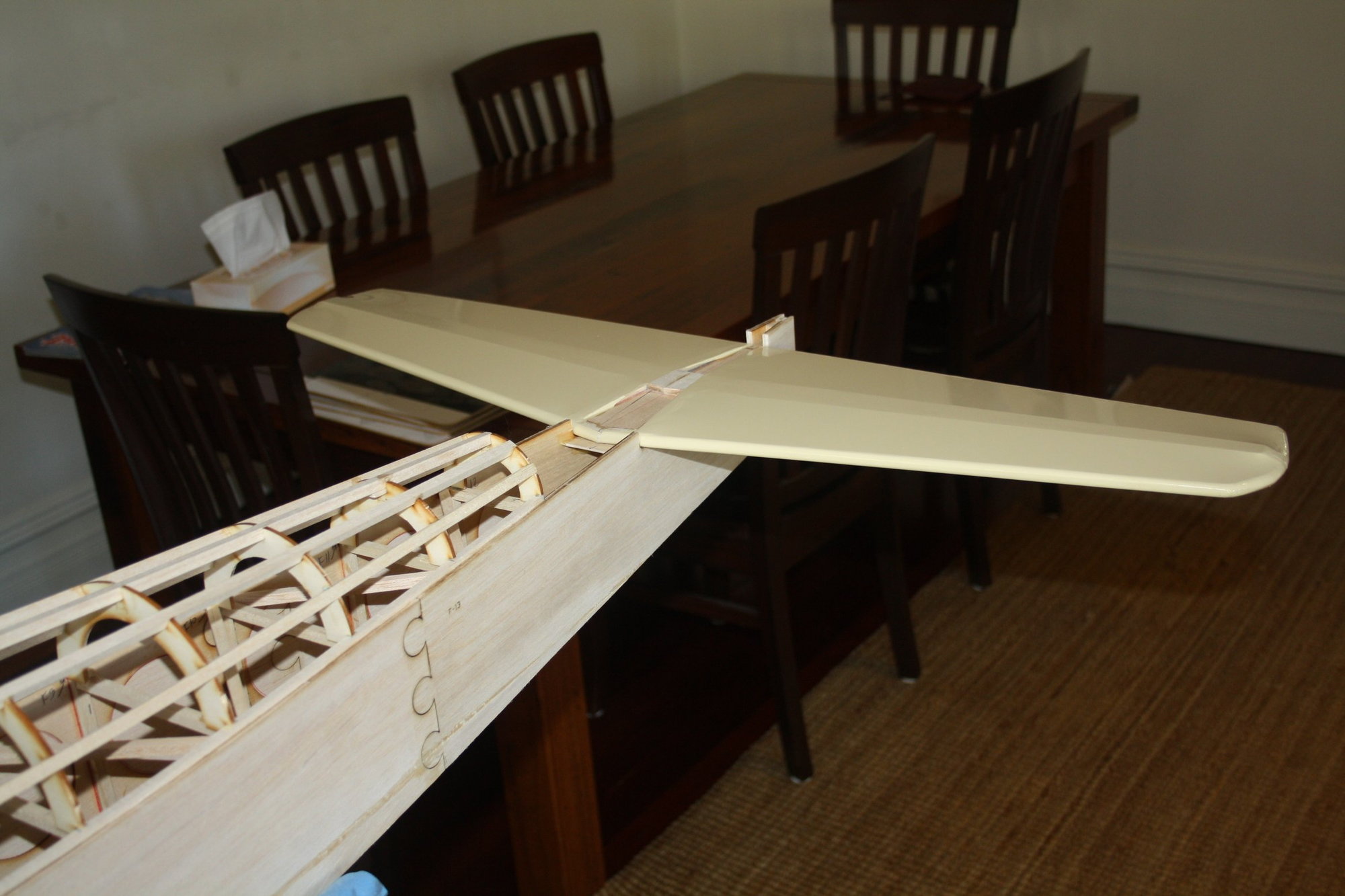
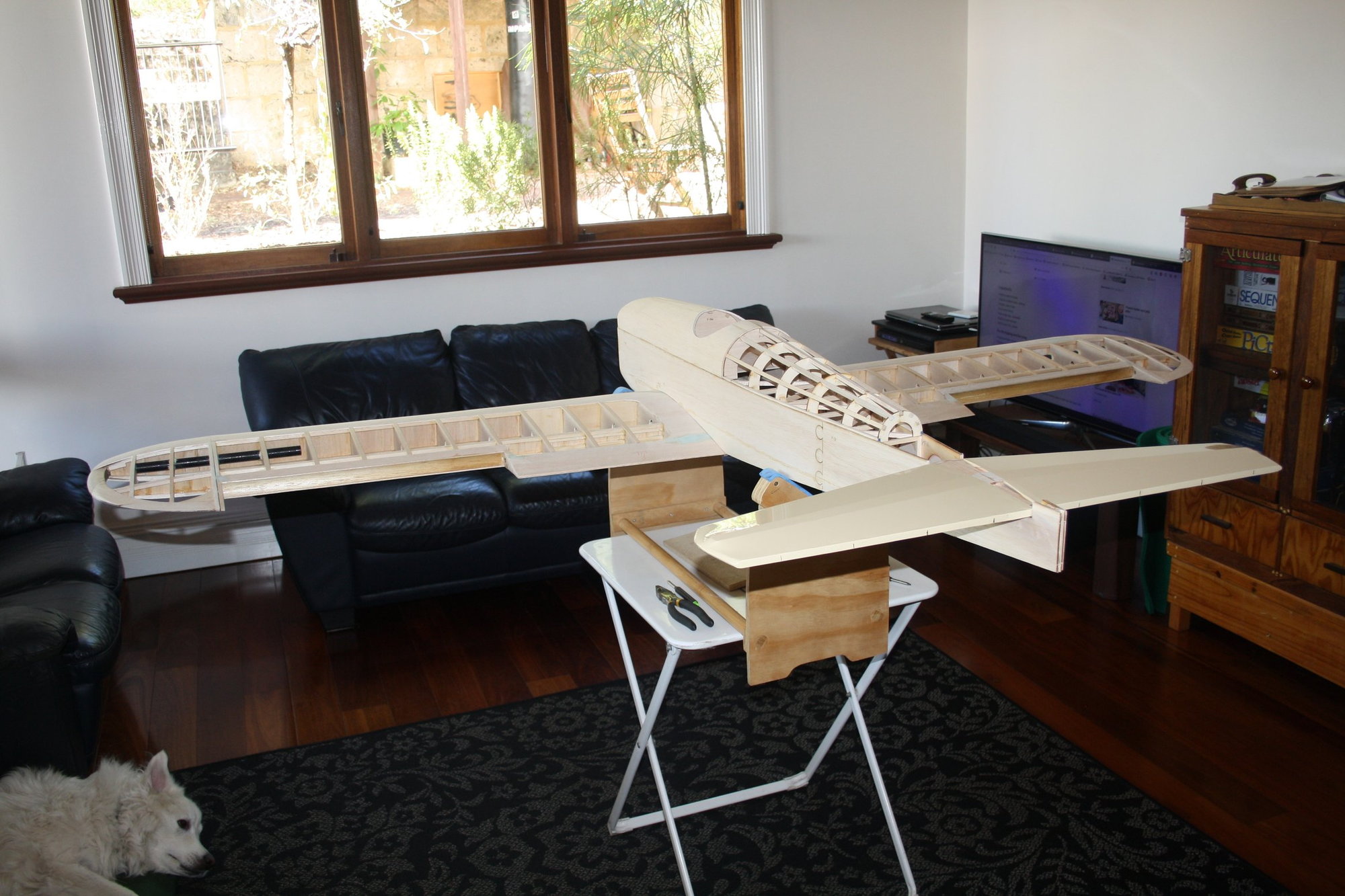
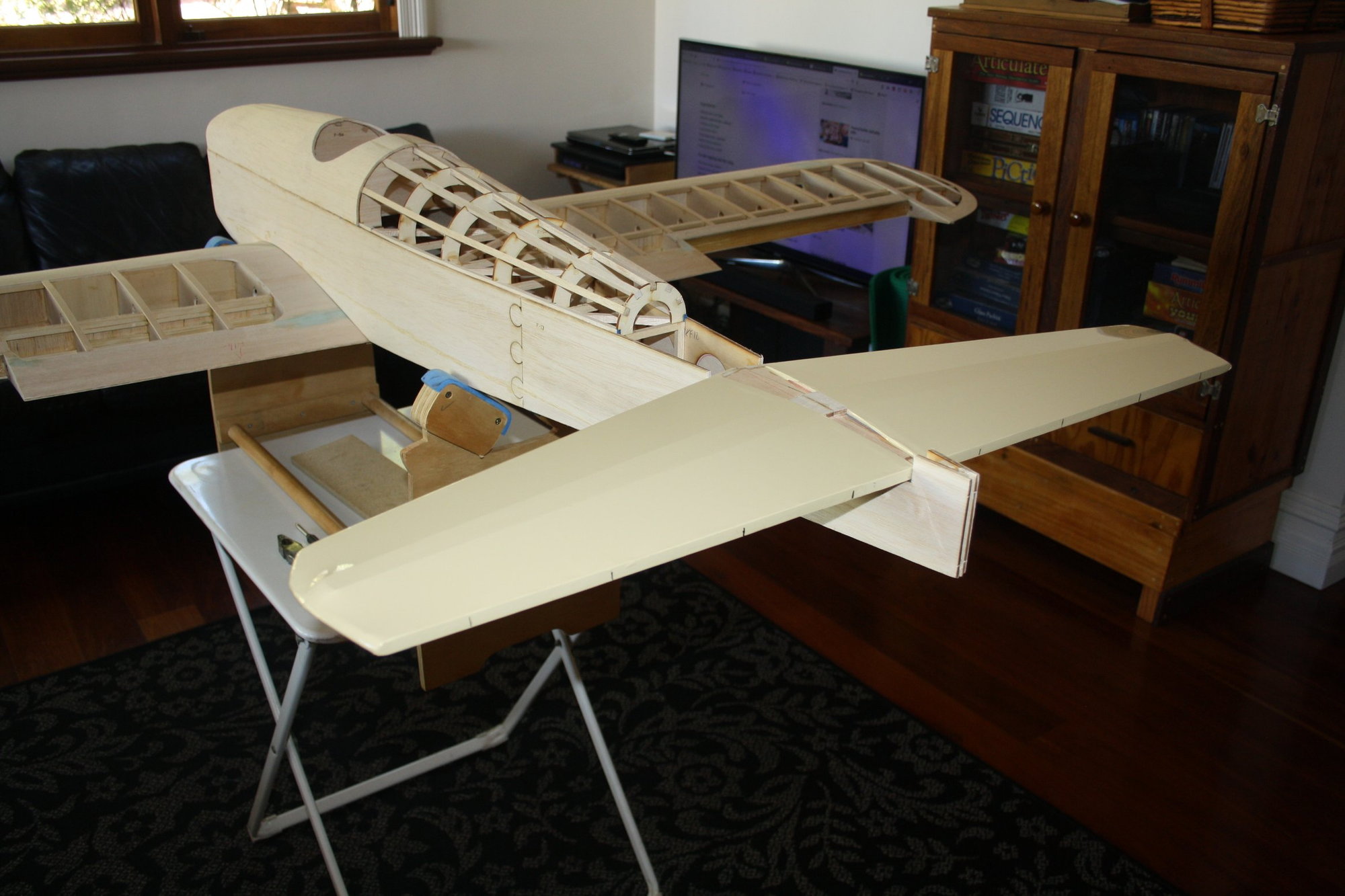
After completing some more covering (ailerons and the vertical fin), I assembled the wing to the fuselage for the first time using the front two mounting bolts. I then measured and set the alignment which required minor sanding enlarging the wing-bolts exit holes.
Once this was done, I marked and drilled the other two wing-bolts holes (for the four wing-bolts setup).
With this done, I placed the horizontal stabiliser in place and measured / checked that it aligns with the wing. It all aligns reasonably well so far.

Cheers,
Eran
After completing some more covering (ailerons and the vertical fin), I assembled the wing to the fuselage for the first time using the front two mounting bolts. I then measured and set the alignment which required minor sanding enlarging the wing-bolts exit holes.
Once this was done, I marked and drilled the other two wing-bolts holes (for the four wing-bolts setup).
With this done, I placed the horizontal stabiliser in place and measured / checked that it aligns with the wing. It all aligns reasonably well so far.
Cheers,
Eran