


Flitfire Cub
 07-08-2022, 08:43 AM
#26

Thread Starter
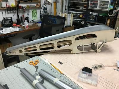
Before I can start covering, actually even before I can start filling and sanding, there are a few loose ends to tie up. Yesterday’s efforts focused on creating a secure space for the flight battery. Remember, this 37-year old design assumed that a .40-size glow engine would propel it, not an electric motor.
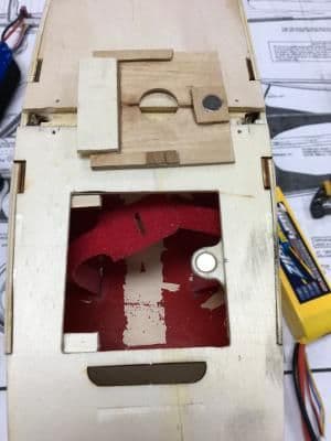
After some measuring and guessing, mostly the latter, I cut a rectangle from the fuselage bottom just behind the firewall. I used a thin cut-off wheel hoping to salvage the cut-out for the hatch cover, but with my shaky hands that was not to be.
Regardless, I was committed. The pictures tell the rest of the story.
Even with a narrow cut-off wheel on a 90-degree adapter . . .
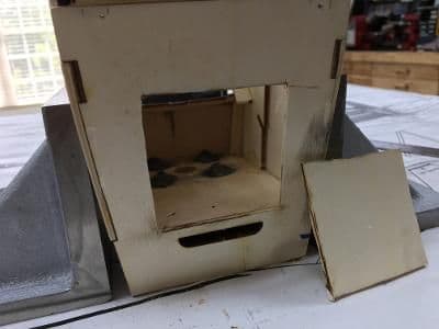
I couldn't salvage the cut-out to use as the hatch cover.
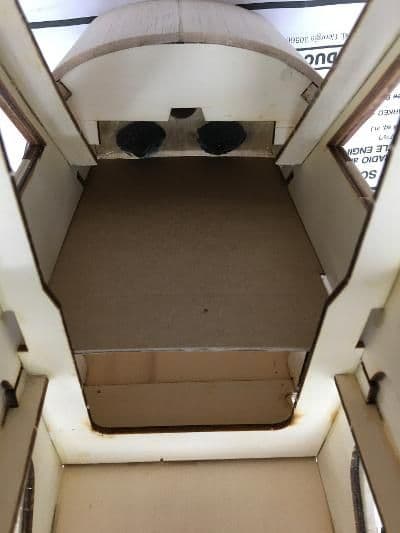
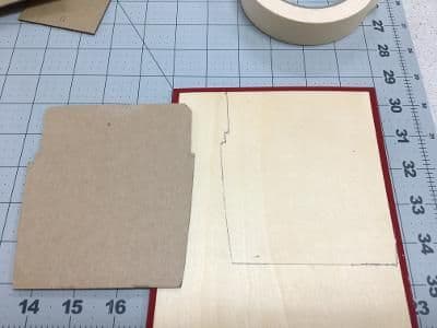
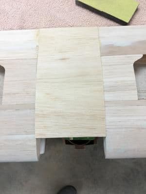
Next up, a floor for the battery. Here you can see a cardboard pattern snugly fitting between the forward fuselage sides.
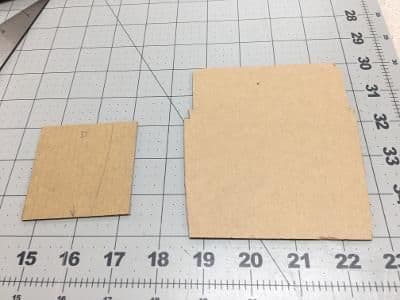
Here we have cardboard patterns for both the battery floor and the hatch cover. Note the subtle curves and notches in the floor necessary for a good fit.
I found a large piece of 1/16" ply in the scrap pile onto which I traced the floor pattern. Then, it was off to the scroll saw.
After a few passes on the disc sander, the plywood floor snapped into place.
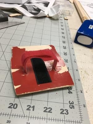
I got the floor ready for installation by attaching all the Velcro. Much easier to do before the floor gets permanently glued in.
Here the floor is glued in and reinforced with balsa tri stock.
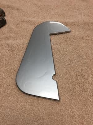
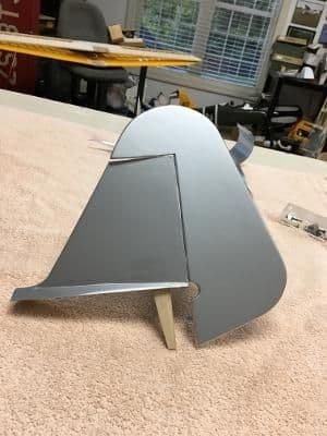
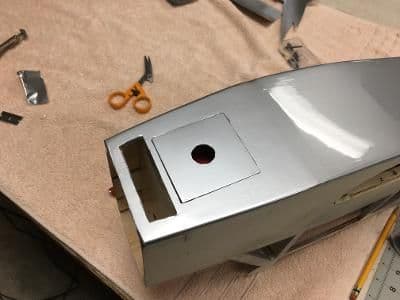
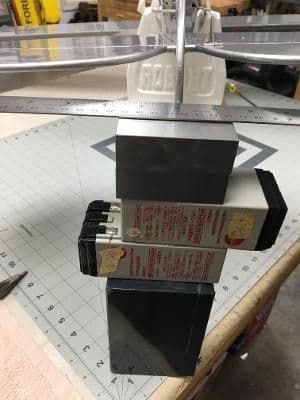
Now that the battery floor was in place, it was time to fabricate a hatch. Using scraps and some magnets from my stash, this is what I ended up with. Pretty ugly, huh?
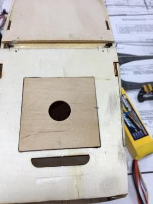
But, this doesn't look so bad. Covering will minimize the small gaps.
There are still some fiddly bits to take care of, but finishing should start by the weekend.
After some measuring and guessing, mostly the latter, I cut a rectangle from the fuselage bottom just behind the firewall. I used a thin cut-off wheel hoping to salvage the cut-out for the hatch cover, but with my shaky hands that was not to be.
Regardless, I was committed. The pictures tell the rest of the story.
Even with a narrow cut-off wheel on a 90-degree adapter . . .
I couldn't salvage the cut-out to use as the hatch cover.
Next up, a floor for the battery. Here you can see a cardboard pattern snugly fitting between the forward fuselage sides.
Here we have cardboard patterns for both the battery floor and the hatch cover. Note the subtle curves and notches in the floor necessary for a good fit.
I found a large piece of 1/16" ply in the scrap pile onto which I traced the floor pattern. Then, it was off to the scroll saw.
After a few passes on the disc sander, the plywood floor snapped into place.
I got the floor ready for installation by attaching all the Velcro. Much easier to do before the floor gets permanently glued in.
Here the floor is glued in and reinforced with balsa tri stock.
Now that the battery floor was in place, it was time to fabricate a hatch. Using scraps and some magnets from my stash, this is what I ended up with. Pretty ugly, huh?
But, this doesn't look so bad. Covering will minimize the small gaps.
There are still some fiddly bits to take care of, but finishing should start by the weekend.
Last edited by GiantModeler; 07-08-2022 at 08:46 AM. Reason: Correct spelling
 07-09-2022, 12:02 PM
#27
Thread Starter
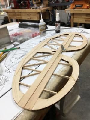
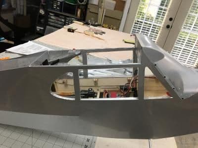
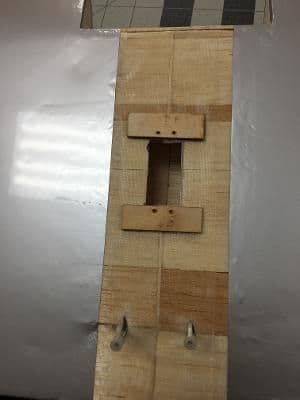
I prefer to install everything I can in the fuselage before it gets covered. Access afterward tends to be restricted, especially in non-giant-scale models like the 1/5.5 scale Goldberg Cub. Thus, I spent yesterday constructing and mounting the control system for the tail feathers.
With the pushrods already fabricated, I had to come up with some stuff to connect. But first, the elevator and rudder needed to move freely, so it was time to bevel and hinge.
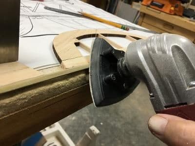
Here I'm using a multi-tool with a sanding head to make the first pass.
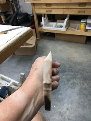
I followed with a sanding bar to achieve this bevel.
Here the elevator has been hinged. I used the same process as outlined in Post #21.
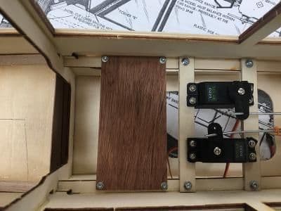
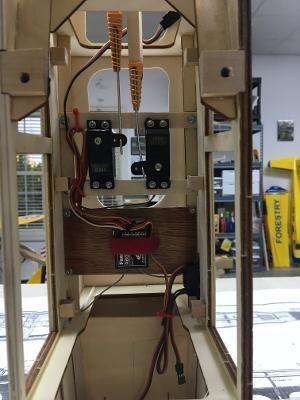
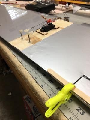
Next up, positioning the servos. Because I had used the plans to fabricate the pushrods, I was pretty much restricted to where the servos were shown on the plans.
I made up servo rails from double layers of 1/8" ply left over from the kit. The first one went in where indicated on the plans; the second was located by the servos I used.
Here, the second rail and the servos are screwed down. I connected the front end of the pushrods with . . .
zee bends. At the other end, standard clevises plugged into kit-supplied control horns.
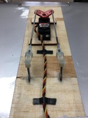
Finally, making sure that everything worked as intended.
I immobilized the elevator and rudder in neutral positions before attaching clevises to control horns, then ran the servos through their range of motions to insure that there was no interference between the pushrods.
Unfortunately, while checking pushrod interference I forget that the control surfaces themselves might be clashing. Here's the result.
Fortunately, it was a clean break, easily repaired. And, yes, I have used my radio to tame the servo travel, hopefully eliminating further interference.
With the pushrods already fabricated, I had to come up with some stuff to connect. But first, the elevator and rudder needed to move freely, so it was time to bevel and hinge.
Here I'm using a multi-tool with a sanding head to make the first pass.
I followed with a sanding bar to achieve this bevel.
Here the elevator has been hinged. I used the same process as outlined in Post #21.
Next up, positioning the servos. Because I had used the plans to fabricate the pushrods, I was pretty much restricted to where the servos were shown on the plans.
I made up servo rails from double layers of 1/8" ply left over from the kit. The first one went in where indicated on the plans; the second was located by the servos I used.
Here, the second rail and the servos are screwed down. I connected the front end of the pushrods with . . .
zee bends. At the other end, standard clevises plugged into kit-supplied control horns.
Finally, making sure that everything worked as intended.
I immobilized the elevator and rudder in neutral positions before attaching clevises to control horns, then ran the servos through their range of motions to insure that there was no interference between the pushrods.
Unfortunately, while checking pushrod interference I forget that the control surfaces themselves might be clashing. Here's the result.
Fortunately, it was a clean break, easily repaired. And, yes, I have used my radio to tame the servo travel, hopefully eliminating further interference.
07-09-2022, 12:16 PM
#28
My Feedback: (6)
Join Date: Nov 2004
Location: Clemmons, NC
Posts: 21
Likes: 0
Received 0 Likes
on
0 Posts
Oops! I won't confirm or deny I've done the same  . Looking good Bren.
You might want to make note of the potential for elevator/rudder interference, as part of a package to give the person who wins this plane. I say this because unless you're giving the winner your radio as well, this could happen again. Although, once covered the surfaces are less likely to cause breakage like what happened here.
Keep Calm and Start Covering!
Greg
. Looking good Bren.You might want to make note of the potential for elevator/rudder interference, as part of a package to give the person who wins this plane. I say this because unless you're giving the winner your radio as well, this could happen again. Although, once covered the surfaces are less likely to cause breakage like what happened here.
Keep Calm and Start Covering!
Greg
07-09-2022, 12:52 PM
#29
Thread Starter
Greg,
Thanks for the heads up. I might just move the pushrods in at the servo ends to reduce throw mechanically.
There are just a few more items on the checklist before I can start covering.
Take care,
Bfren
Thanks for the heads up. I might just move the pushrods in at the servo ends to reduce throw mechanically.
There are just a few more items on the checklist before I can start covering.
Take care,
Bfren
07-10-2022, 10:56 AM
#30
Thread Starter
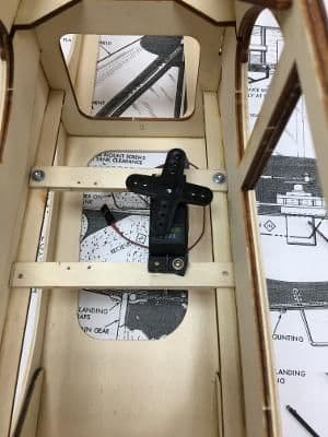
In the old days, when a project reached this stage, you would just wrap your receiver and battery in foam and stuff them under the fuel tank. That�s what the plans show. But nowadays, with smooth-running outrunners you can dispense with the foam. And, if you have an ESC with a BEC, the battery as well.
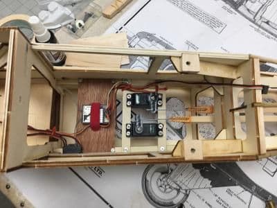
So, I fabricated a shelf to hold the receiver. And, while I was at it, installed a switch in the recommended location.
Here's the shelf, scrap 1.0 mm ply that I salvaged from packing material years ago.
Here's the shelf fastened to the side rails with #2 hardware.
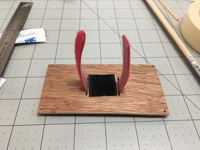
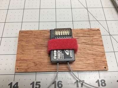
The two photos above show the Velcro installation.

Then, the shelf went back in and the antennas located inside scrap plastic tubing, both . . .
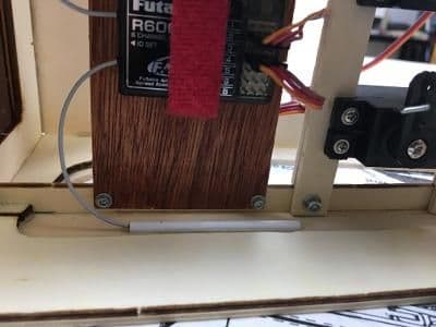
horizontally and . . .
vertically.
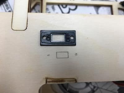
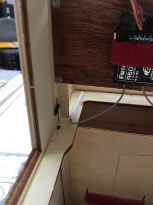
Next up, the receiver switch. Because this connects the ESC to the RX, it has three wires.
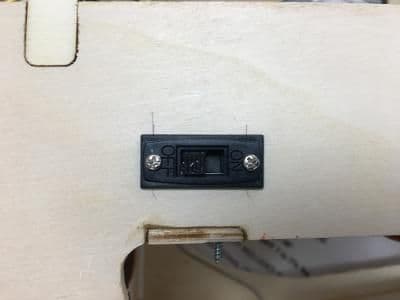
Here it is, installed pretty close to the recommended location.
All done.
So, I fabricated a shelf to hold the receiver. And, while I was at it, installed a switch in the recommended location.
Here's the shelf, scrap 1.0 mm ply that I salvaged from packing material years ago.
Here's the shelf fastened to the side rails with #2 hardware.
The two photos above show the Velcro installation.
Then, the shelf went back in and the antennas located inside scrap plastic tubing, both . . .
horizontally and . . .
vertically.
Next up, the receiver switch. Because this connects the ESC to the RX, it has three wires.
Here it is, installed pretty close to the recommended location.
All done.
07-10-2022, 11:37 AM
#31

Well, Bren, the build is coming right along.
I like the repurposed thin ply. I too have quite a collection of such materials that have been pigeonholed for that occasion that one of my builds could use it. I even have various material like some thin faux leather for making up some semi-scale interior components.
I agree with the mechanical adjustments on the control surface travels. By dialing everything out of the travel electronically you can loose some of the resolution on the proportional travel.
I know it has become uncommon to wrap receivers as you mentioned. And not many people do from what i see.
But, I have been known to crash one once in a while. So, I still wrap my receivers to protect them from impact on one of those occasions.")
I just use some of that large cell packing type foam to keep from holding in too much heat. (also actual repurpose from packing)
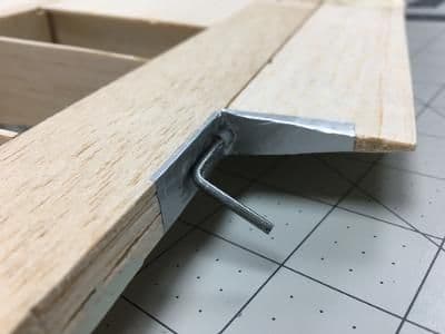
I also noticed after re-reading your post 21 that you had already mentioned what I illustrated in post 22. . But hey, it gave me a chance to draw it up and participate in your thread rather than just reading it. A little interaction always makes these threads a little more fun....
I like the repurposed thin ply. I too have quite a collection of such materials that have been pigeonholed for that occasion that one of my builds could use it. I even have various material like some thin faux leather for making up some semi-scale interior components.
I agree with the mechanical adjustments on the control surface travels. By dialing everything out of the travel electronically you can loose some of the resolution on the proportional travel.
I know it has become uncommon to wrap receivers as you mentioned. And not many people do from what i see.
But, I have been known to crash one once in a while. So, I still wrap my receivers to protect them from impact on one of those occasions.
I just use some of that large cell packing type foam to keep from holding in too much heat. (also actual repurpose from packing)
I also noticed after re-reading your post 21 that you had already mentioned what I illustrated in post 22.
. But hey, it gave me a chance to draw it up and participate in your thread rather than just reading it. A little interaction always makes these threads a little more fun....
07-10-2022, 12:34 PM
#32
Thread Starter
Rick,
I'm afraid I must disagree. Interaction makes these threads a LOT more fun! As well as informative for both posters and lurkers.
Thank you for looking in and for commenting.
Take care,
Bren
I'm afraid I must disagree. Interaction makes these threads a LOT more fun! As well as informative for both posters and lurkers.
Thank you for looking in and for commenting.
Take care,
Bren
07-11-2022, 08:05 AM
#33
Thread Starter
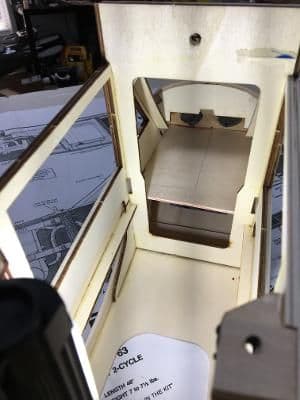
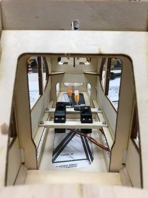
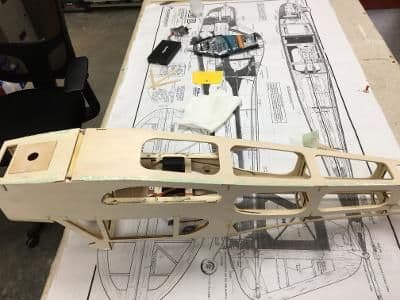
Despite my declaration in Post #1 not to go crazy on scale details, I could not allow the innards of this model to show. Also, I needed a platform on which to place the pilot. The directions suggest making a shelf just large enough to hold the pilot figure, so why not extend that platform to the entirety of the cockpit?
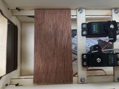
Therefore, I decided to fabricate a raised �floor� both to support the pilot figure and to hide the electronics. It will end up flat black, but initially it was more of that thin, but stiff, salvage plywood that I used for the receiver shelf.
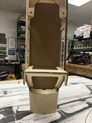
It took less than an hour to trim some cardboard to fit. Not only will this be used to cut the plywood pieces, but also to mask the electronics when I spray the cockpit interior silver.
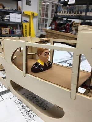
I placed the pilot figure on the cardboard to assure that his vertical position was correct. Is it my imagination, or does he look a little apprehensive?
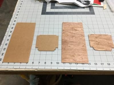
Using the cardboard patterns, I cut the plywood.
I must have measured twice, because the ply pieces fit.
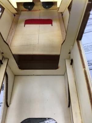
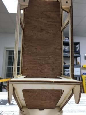
To support the "floor" I cut 10 3/8" cubic support blocks from leftover basswood spar material, shown here glued to the fuse sides.
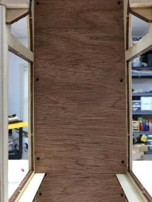
Finally, the plywood "floor" screwed to the support blocks with black M1.7 x 8 sheet metal screws. I expect they will blend in once I paint the ply flat black.
Therefore, I decided to fabricate a raised �floor� both to support the pilot figure and to hide the electronics. It will end up flat black, but initially it was more of that thin, but stiff, salvage plywood that I used for the receiver shelf.
It took less than an hour to trim some cardboard to fit. Not only will this be used to cut the plywood pieces, but also to mask the electronics when I spray the cockpit interior silver.
I placed the pilot figure on the cardboard to assure that his vertical position was correct. Is it my imagination, or does he look a little apprehensive?
Using the cardboard patterns, I cut the plywood.
I must have measured twice, because the ply pieces fit.
To support the "floor" I cut 10 3/8" cubic support blocks from leftover basswood spar material, shown here glued to the fuse sides.
Finally, the plywood "floor" screwed to the support blocks with black M1.7 x 8 sheet metal screws. I expect they will blend in once I paint the ply flat black.
07-12-2022, 04:19 PM
#34
Thread Starter
All the advice articles tell you that unless your balsa and plywood are baby smooth, your resulting iron-on covering will turn out terrible. While I have found this to be an exaggeration, nicks, divots, and lumps, and bumps will show up. However, pinholes will not. Indeed, I normally Woodpeck balsa and ply, creating a field of tiny pits, to minimize air bubbles. Those surfaces always appear smooth after covering.
Before I could even think about covering, however, there were some important details to clear up. Well, actually, only two. It was a slow day.
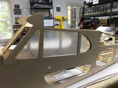
First up, shaping the window cut-outs for the pre-formed windows. Here, I have fitted the front and center panes, but the rear one is giving me ulcers.
A few passes with a sanding drum resulted in . . .
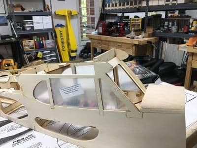
perfect fits all the way around. (The panes look cloudy because they still have protective films applied.)
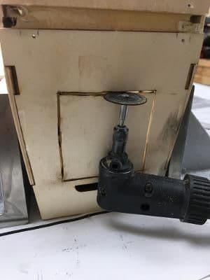
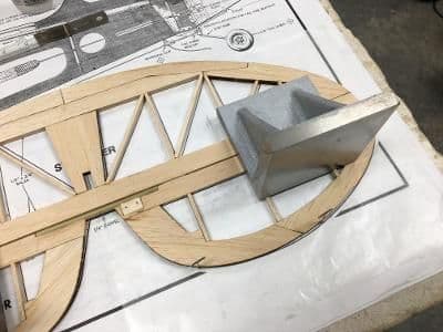
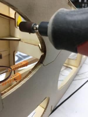
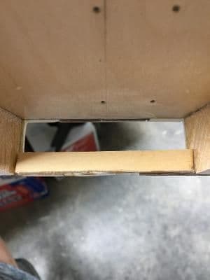
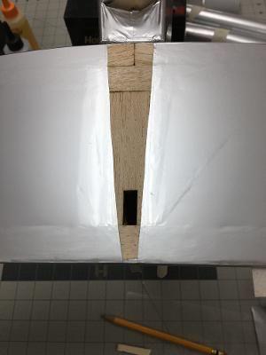
I decided to enlarge a slot in the bottom of the fuselage in front of the firewall to allow more air flow. The new, larger hole then required some reinforcement.
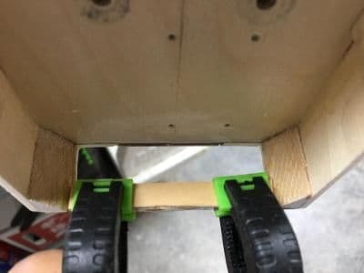
Air exhaust hole with reinforcement glued on and clamped.
With this, I had created and/or adjusted all the holes intended for the fuselage.
It was time to fill and sand the unintended holes and divots.
Before I could even think about covering, however, there were some important details to clear up. Well, actually, only two. It was a slow day.
First up, shaping the window cut-outs for the pre-formed windows. Here, I have fitted the front and center panes, but the rear one is giving me ulcers.
A few passes with a sanding drum resulted in . . .
perfect fits all the way around. (The panes look cloudy because they still have protective films applied.)
I decided to enlarge a slot in the bottom of the fuselage in front of the firewall to allow more air flow. The new, larger hole then required some reinforcement.
Air exhaust hole with reinforcement glued on and clamped.
With this, I had created and/or adjusted all the holes intended for the fuselage.
It was time to fill and sand the unintended holes and divots.
Last edited by GiantModeler; 07-12-2022 at 04:21 PM. Reason: Cleaned up spacing
07-13-2022, 10:25 AM
#35
Thread Starter
Time to fill the dents and gouges. But before I did that, I gave the flat portions of the fuselage some passes with a random orbital palm sander. This works wonders on plywood, removing CA blobs without cutting into the underlying wood as long as you keep the sander moving.
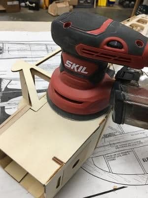
I got this sander for $12 on one of the Amazon Prime days last year (with free next day delivery)! If you keep it moving it's very safe to use on lite ply or anything harder.
My preferred filler is UPOL Dolphin Glaze, a two-part, fast-setting putty that sands like lite ply. It is fiddly to get the proportions correct, but becomes easier with practice. It is also quite expensive and hard to find in local stores, but a $25 investment should take care of at least four large models, maybe more.
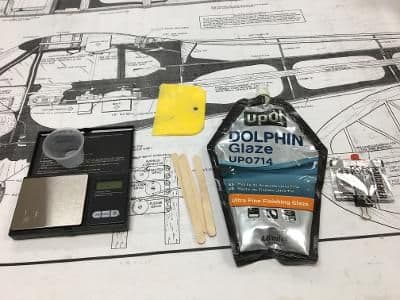
Here's what you need to use Dolphin Glaze. From left to right: mixing cup, micro scale, plastic spreader (for large areas), mixing sticks (for blending and dabbing), glaze, and hardener.
On plywood I use an oscillating multitool with a sanding head to knock the glaze almost level with the wood and finish with a 240-grit sanding block.
I got this much of the fuselage filled with about 5 grams of Dolphin Glaze. You can start sanding it in about 20 minutes.
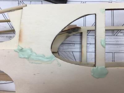
I filled these holes before quitting for the day by simply dabbing DG into the crevices. It hardened completely overnight.
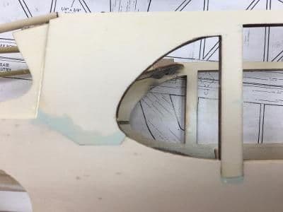
In the morning, despite being as hard as it would ever get, the glaze looked like this after 30 seconds with the multitool sander and 10 seconds of swiping with a block.
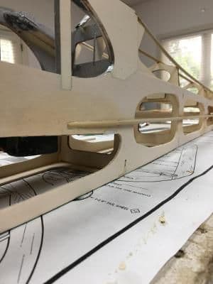
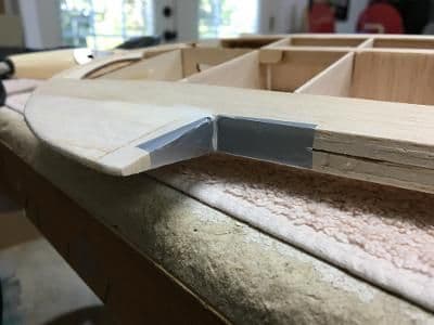
Once everything was filled and sanded flush, it was time to do some rounding. The bottom edge of the fuselage should not be a sharp corner, for example. And there were other places where a little softening will look like tubular supports once the Ultracote goes on.
Surprisingly little elbow grease produced a nice radius where the fuselage slabs meet. I was trying for 3/32". What do you think?
Finally, I added a fake stringer to the fuselage side from under the rear window to the tail.
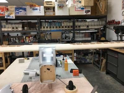
Time to cover! Oh, wait. I still have to prepare the wing.
I got this sander for $12 on one of the Amazon Prime days last year (with free next day delivery)! If you keep it moving it's very safe to use on lite ply or anything harder.
My preferred filler is UPOL Dolphin Glaze, a two-part, fast-setting putty that sands like lite ply. It is fiddly to get the proportions correct, but becomes easier with practice. It is also quite expensive and hard to find in local stores, but a $25 investment should take care of at least four large models, maybe more.
Here's what you need to use Dolphin Glaze. From left to right: mixing cup, micro scale, plastic spreader (for large areas), mixing sticks (for blending and dabbing), glaze, and hardener.
On plywood I use an oscillating multitool with a sanding head to knock the glaze almost level with the wood and finish with a 240-grit sanding block.
I got this much of the fuselage filled with about 5 grams of Dolphin Glaze. You can start sanding it in about 20 minutes.
I filled these holes before quitting for the day by simply dabbing DG into the crevices. It hardened completely overnight.
In the morning, despite being as hard as it would ever get, the glaze looked like this after 30 seconds with the multitool sander and 10 seconds of swiping with a block.
Once everything was filled and sanded flush, it was time to do some rounding. The bottom edge of the fuselage should not be a sharp corner, for example. And there were other places where a little softening will look like tubular supports once the Ultracote goes on.
Surprisingly little elbow grease produced a nice radius where the fuselage slabs meet. I was trying for 3/32". What do you think?
Finally, I added a fake stringer to the fuselage side from under the rear window to the tail.
Time to cover! Oh, wait. I still have to prepare the wing.
Last edited by GiantModeler; 07-13-2022 at 10:34 AM. Reason: Correct spelling
07-14-2022, 05:21 PM
#36
Thread Starter
Not much to say here. Except that I finally got to use a tool I "just had to buy immediately" more than 25 years ago then languished in a shoe box until a recent shop reorganization.
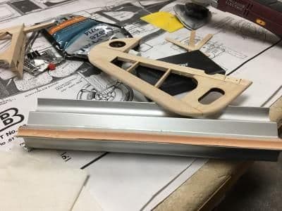
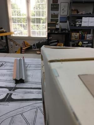
Here it is: an 11-inch, extruded aluminum contour support for sticky sandpaper. Not much use for this when all you're doing is assembling ARFs.
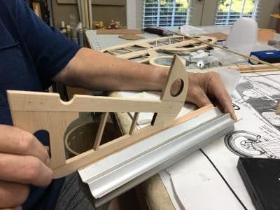
Here, I used it to round the edges of the rudder. Similarly, I rounded the edges or the other tailfeather components.
Here it is: an 11-inch, extruded aluminum contour support for sticky sandpaper. Not much use for this when all you're doing is assembling ARFs.
Here, I used it to round the edges of the rudder. Similarly, I rounded the edges or the other tailfeather components.
Last edited by GiantModeler; 07-14-2022 at 05:22 PM. Reason: Cleaned up spacing
07-18-2022, 10:25 AM
#37
Thread Starter
I spent the past few miserable days trying to get the wing ready to cover. Unlike the fuselage, which is mostly plywood, and the tail surfaces, which are mostly flat, the wing is neither. It�s mostly (fragile) balsa and curves. Care must be taken when filling and sanding not to nick adjacent components and create more items to repair.
The wing�s center section and leading edges gave me the most misery. The center section because the fiberglass reinforcement had to be hidden without scarring the nearby sheeting. The LEs because they consisted of balsa glued to hardwood dowels with CA, none of which sands at the same rate.
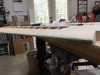
Regardless, I got �er done, although there was about 10 times as much filler dust on the floor than there was Dolphin Glaze on the wing by the time I finished. I got so frustrated that I took only random photos rather than a sequence that told a story.
The wing upper center section slathered with Dolphin Glaze.
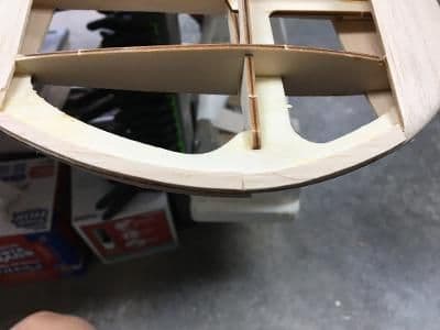
During pauses in bouts between filler and sandpaper, I added some 3/32" balsa filler to the wingtips to promote covering adhesion.
Here, you can see the initial filling of the right wing leading edge. It took three, with much sanding in between
Nevertheless, the whole shebang was now ready for Ultracote.
The wing�s center section and leading edges gave me the most misery. The center section because the fiberglass reinforcement had to be hidden without scarring the nearby sheeting. The LEs because they consisted of balsa glued to hardwood dowels with CA, none of which sands at the same rate.
Regardless, I got �er done, although there was about 10 times as much filler dust on the floor than there was Dolphin Glaze on the wing by the time I finished. I got so frustrated that I took only random photos rather than a sequence that told a story.
The wing upper center section slathered with Dolphin Glaze.
During pauses in bouts between filler and sandpaper, I added some 3/32" balsa filler to the wingtips to promote covering adhesion.
Here, you can see the initial filling of the right wing leading edge. It took three, with much sanding in between
Nevertheless, the whole shebang was now ready for Ultracote.
07-19-2022, 01:21 PM
#38
Thread Starter
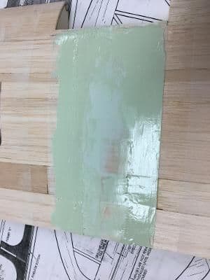
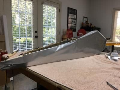
To make this Goldberg Cub look like a Flitfire I chose silver Ultracote. I prefer UC over other brands because I believe less of what�s underneath shows through. I understand that it�s a little heavier, but on the type and size models I build it doesn�t matter much in the end.
I was excited to find a cut pattern in the instruction booklet. But that euphoria quickly faded when I realized that, back in the day, rolls of iron-on covering were 27� wide. Today�s versions measure only 23.5� in width. I think this is called �shrinkflation.�
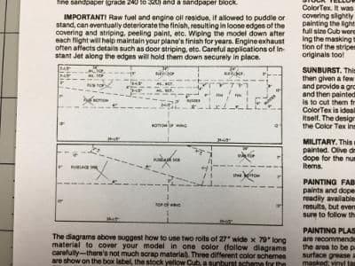
This cut pattern would have worked fine except that it's for 27"-wide covering. Today's versions are 23.5"
Regardless, I cleared the bench and set it up for covering.
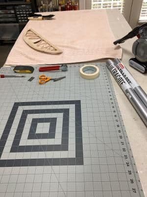
Far end covered with a towel; this is where ironing will take place. Cutting mat at near end.
Even though I knew that the Goldberg pattern was useless overall, I did use it to cut pieces for the horizontal stabilizer and elevator and went to work. Covering these components took until mid-afternoon.
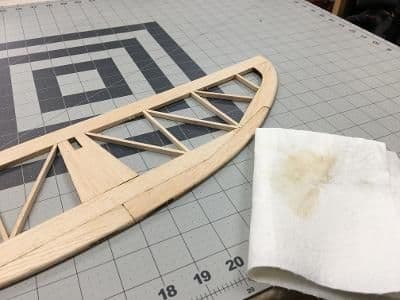
Here, I have Woodpecked and fine sanded the horizontal stabilizer. Then I wiped it with an alcohol-soaked paper towel.
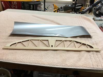
Prior to ironing the covering on the stab.
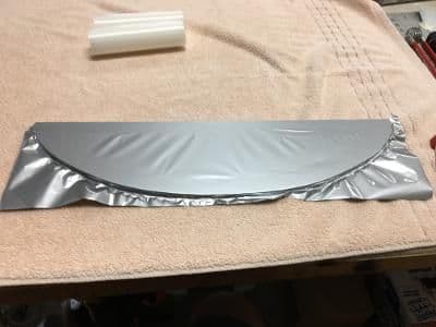
Covering ironed on but not trimmed or tightened.
Here it is trimmed and tightened.
Both the stab and elevator have been covered, trimmed, and shrunk. I have also hinged them and installed the control horn. The assembly is ready to install.
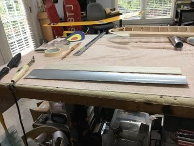
Then, I decided to stop covering and to lay out and cut the remaining pieces. It took the remainder of the first roll for the fuselage bottom, top, and sides. It required a second entire roll for the wing pieces and about half of a third for everything else.
All covering cut to size; much of it rolled back up and labeled.
Having all the covering cut and at hand, I looked forward to getting back to ironing, stretching, heating, and tugging (and cussin').
I was excited to find a cut pattern in the instruction booklet. But that euphoria quickly faded when I realized that, back in the day, rolls of iron-on covering were 27� wide. Today�s versions measure only 23.5� in width. I think this is called �shrinkflation.�
This cut pattern would have worked fine except that it's for 27"-wide covering. Today's versions are 23.5"
Regardless, I cleared the bench and set it up for covering.
Far end covered with a towel; this is where ironing will take place. Cutting mat at near end.
Even though I knew that the Goldberg pattern was useless overall, I did use it to cut pieces for the horizontal stabilizer and elevator and went to work. Covering these components took until mid-afternoon.
Here, I have Woodpecked and fine sanded the horizontal stabilizer. Then I wiped it with an alcohol-soaked paper towel.
Prior to ironing the covering on the stab.
Covering ironed on but not trimmed or tightened.
Here it is trimmed and tightened.
Both the stab and elevator have been covered, trimmed, and shrunk. I have also hinged them and installed the control horn. The assembly is ready to install.
Then, I decided to stop covering and to lay out and cut the remaining pieces. It took the remainder of the first roll for the fuselage bottom, top, and sides. It required a second entire roll for the wing pieces and about half of a third for everything else.
All covering cut to size; much of it rolled back up and labeled.
Having all the covering cut and at hand, I looked forward to getting back to ironing, stretching, heating, and tugging (and cussin').
07-20-2022, 03:43 AM
#39
Here is a link to some good pictures and info of FlitFire Indiana when it was for sale.
Some pretty nice photographs for scale references...
https://www.akcaviation.com/inventor...3-flitfire-cub
Some pretty nice photographs for scale references...
https://www.akcaviation.com/inventor...3-flitfire-cub
07-20-2022, 03:58 AM
#40
here is the link to the picture shown below:
https://eaavintage.org/wp-content/up.../04/Lineup.jpg
this is the link for the Vintage EAA story on Flitfire
https://eaavintage.org/the-flitfire-cub/
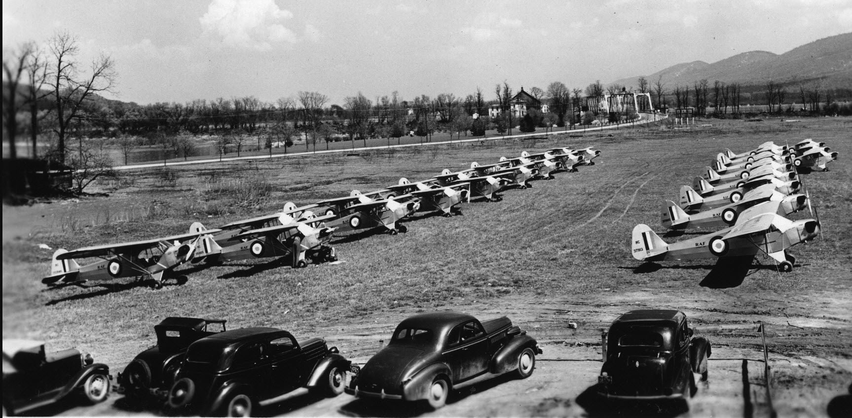
1941 Flitfire Lineup
https://eaavintage.org/wp-content/up.../04/Lineup.jpg
this is the link for the Vintage EAA story on Flitfire
https://eaavintage.org/the-flitfire-cub/
1941 Flitfire Lineup
Last edited by RICKSTUBBZ; 07-20-2022 at 04:02 AM.
07-20-2022, 02:01 PM
#42
Thread Starter
Things moved right along today, with few mistakes, all of which were easy to correct. The fuselage and tail feathers are complete, including painting and bolting on the landing gear and temporarily fastening the windshield.
No problems with the rudder.
I had a little struggle with the concavity of the lower part of the fin, but with enough tugging and heating, I got it covered to my satisfaction. Here, it's hinged to the rudder and the assembly is ready for installation.
Before starting the fuselage, I visited the paint booth with the LG wires and brackets.
Here they are, painted silver.
As is customary, I started with the bottom. It's the only surface that's completely flat, so it was a breeze.
I went ahead an covered the hatch cover and it still fit!
Here, the right side is tacked on.
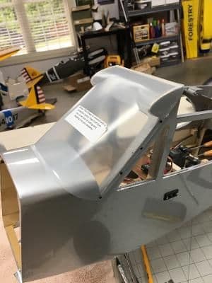
And here, the entire fuselage has been covered and the windshield temporarily installed. I'll take it off after the test flights for removal of the protective covering and subsequent painting.
Tomorrow, I should at least get started on the wing.
No problems with the rudder.
I had a little struggle with the concavity of the lower part of the fin, but with enough tugging and heating, I got it covered to my satisfaction. Here, it's hinged to the rudder and the assembly is ready for installation.
Before starting the fuselage, I visited the paint booth with the LG wires and brackets.
Here they are, painted silver.
As is customary, I started with the bottom. It's the only surface that's completely flat, so it was a breeze.
I went ahead an covered the hatch cover and it still fit!
Here, the right side is tacked on.
And here, the entire fuselage has been covered and the windshield temporarily installed. I'll take it off after the test flights for removal of the protective covering and subsequent painting.
Tomorrow, I should at least get started on the wing.
Last edited by GiantModeler; 07-20-2022 at 03:27 PM. Reason: Spelling and grammar
07-22-2022, 02:45 PM
#43
Thread Starter
Things veered off course soon after.
First, I did to the wing what I should have done at first: I skinned the upper center section with 1/32” balsa. This covered the mottled catastrophe that resulted from trying to level that area with glaze.
This should sand out easily and smoothly and cover the irregularities that remained after several applications of glaze.
However, while waiting for the glue to set, I began working on other details that needed completion before the test flights. Such as:
Side window installation.
Here they are in place fastened with canopy glue. I even remembered to remove the protective coating!
Aligning and installing the tail surfaces.

Here, I have dry-positioned the horizontal stabilizer to assure . . .
that it was level with the wing.
I epoxied the stab to the fuse and trimmed the Ultracote to provide a gluing surface for the fin.

Here, the fin is epoxied in place and stabilized while the glue cures.
I went ahead and permanently hinged the elevator and rudder. This is the final hinge positioning before thin CA application.
Tailwheel installation.
I'll go back and touch up the white nylon with silver paint later.
Installation of the power system.
It seemed like the firewall area shrunk by 50% or so since I mocked this up earlier in the build.
Positioning and installing the cowl.
Here, I have positioned and taped the cowl in place prior to drilling tiny holes . . .
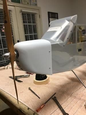
for the M1.7 x 6 chrome-plated sheet metal screws. After the test flights, I intend to paint the cowl to match the fuselage and add some engine detail.
By the time I finished these necessary tasks, the glue on the wing skinning had dried, but it was time for bed.
First, I did to the wing what I should have done at first: I skinned the upper center section with 1/32” balsa. This covered the mottled catastrophe that resulted from trying to level that area with glaze.
This should sand out easily and smoothly and cover the irregularities that remained after several applications of glaze.
However, while waiting for the glue to set, I began working on other details that needed completion before the test flights. Such as:
Side window installation.
Here they are in place fastened with canopy glue. I even remembered to remove the protective coating!
Aligning and installing the tail surfaces.
Here, I have dry-positioned the horizontal stabilizer to assure . . .
that it was level with the wing.
I epoxied the stab to the fuse and trimmed the Ultracote to provide a gluing surface for the fin.
Here, the fin is epoxied in place and stabilized while the glue cures.
I went ahead and permanently hinged the elevator and rudder. This is the final hinge positioning before thin CA application.
Tailwheel installation.
I'll go back and touch up the white nylon with silver paint later.
Installation of the power system.
It seemed like the firewall area shrunk by 50% or so since I mocked this up earlier in the build.
Positioning and installing the cowl.
Here, I have positioned and taped the cowl in place prior to drilling tiny holes . . .
for the M1.7 x 6 chrome-plated sheet metal screws. After the test flights, I intend to paint the cowl to match the fuselage and add some engine detail.
By the time I finished these necessary tasks, the glue on the wing skinning had dried, but it was time for bed.
Last edited by GiantModeler; 07-22-2022 at 02:54 PM. Reason: Cleaned up text
07-23-2022, 10:06 AM
#44
Thread Starter
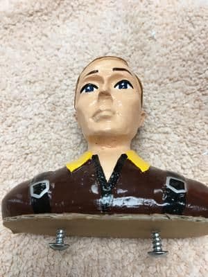
While awaiting my head to get in the right place for the last of the covering, I installed the pilot to the faux cockpit floor. The pictures tell the story better than mere words:
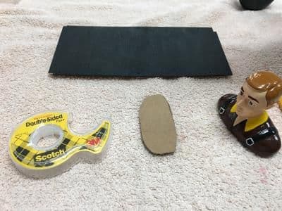
Many of the items needed to fasten the pilot (right) to the faux cockpit floor (top).
Normally, I would just glue the pilot in with silicon caulk or canopy glue. I wanted this one to be removable in case the winner of the model wanted to personalize it. Here, the cardboard pattern is ready to attach to the pilot with double-faced tape.
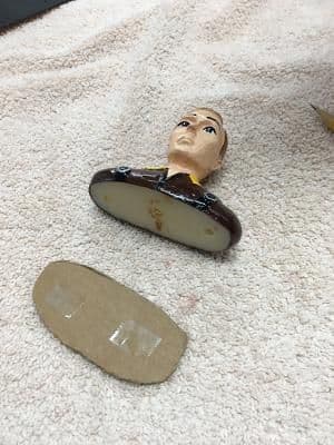
Pattern stuck to pilot and marked for drilling.
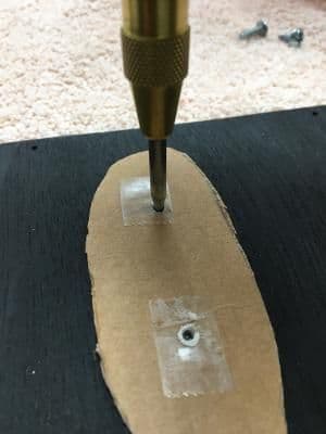
Pilot drilled and screws started.
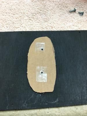
Cardboard pattern transferred to faux floor.
Floor marked for drilling.
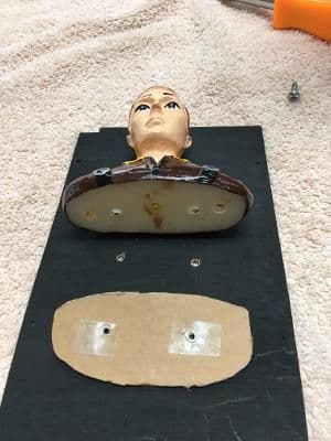
Floor drilled and ready for pilot.
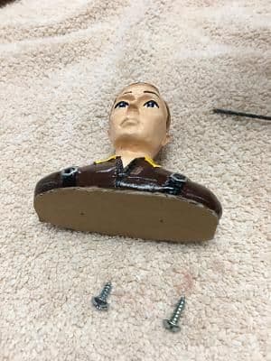
Pilot installed top view and . . .
and bottom.
There are officially no further excuses that I can use to stall. The wing shall be covered.
Many of the items needed to fasten the pilot (right) to the faux cockpit floor (top).
Normally, I would just glue the pilot in with silicon caulk or canopy glue. I wanted this one to be removable in case the winner of the model wanted to personalize it. Here, the cardboard pattern is ready to attach to the pilot with double-faced tape.
Pattern stuck to pilot and marked for drilling.
Pilot drilled and screws started.
Cardboard pattern transferred to faux floor.
Floor marked for drilling.
Floor drilled and ready for pilot.
Pilot installed top view and . . .
and bottom.
There are officially no further excuses that I can use to stall. The wing shall be covered.
07-25-2022, 01:24 PM
#45
Thread Starter
Do you know who first said that? I didn�t until a few minutes ago. It was Fran�ois-Marie Arouet, better known to the world as Voltaire, his nom de plume. Now this is not the same Frenchman for whom the volt was named. That was Alessandro Volta, who first demonstrated electromotive force, what we call voltage today.
So, what on earth does this have to do with covering the wing on a Goldberg Cub? Not much, except that the covering did not come out perfect. But, always one to follow the sage advice of the great philosophers, I did not let that get in the way of saying, �Good enough,� and calling it a day.
The photos below show some of the process.
I prepped all the wood the same way: Woodpeck, final sand, vacuum, and wipe with alcohol. Here, an aileron is ready for silver Ultracote.
Next, the pesky inside corners.
This one required some trimming before installation.
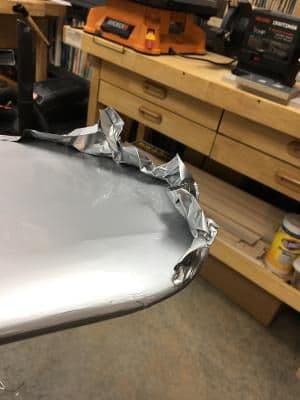
As usual, the wingtips gave me the most flusteration. After heating and pulling, this is what one side looked like.
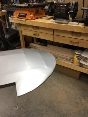
But, after trimming, sealing, and shrinking, the other side didn't come out too bad.
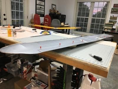
Of course, I forgot to take a picture of the completely covered wing, so here's a preview of final assembly. The ailerons have been epoxied to the control horns and the hinges await the application of thin CA.
By the way, I mentioned Volta because I have converted this Cub from glow to electric. Thank you Alessandro and Ben (Franklin).
So, what on earth does this have to do with covering the wing on a Goldberg Cub? Not much, except that the covering did not come out perfect. But, always one to follow the sage advice of the great philosophers, I did not let that get in the way of saying, �Good enough,� and calling it a day.
The photos below show some of the process.
I prepped all the wood the same way: Woodpeck, final sand, vacuum, and wipe with alcohol. Here, an aileron is ready for silver Ultracote.
Next, the pesky inside corners.
This one required some trimming before installation.
As usual, the wingtips gave me the most flusteration. After heating and pulling, this is what one side looked like.
But, after trimming, sealing, and shrinking, the other side didn't come out too bad.
Of course, I forgot to take a picture of the completely covered wing, so here's a preview of final assembly. The ailerons have been epoxied to the control horns and the hinges await the application of thin CA.
By the way, I mentioned Volta because I have converted this Cub from glow to electric. Thank you Alessandro and Ben (Franklin).
07-26-2022, 07:33 AM
#46
Thread Starter
I spent most of my shop time yesterday taking care of those last minute, but absolutely necessary, details that you must address before that first flight. For example:
Installing the aileron servo.
Here, the servo rails have been epoxied to the underside of the wing.
I secured one aileron in neutral while I adjusted that servo linkage.
Finished. The arms offset to the front will provide aileron differential.
Testing the power system.
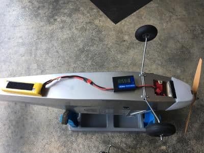
With a 4-cell, 4,500 mAh battery reading 16.6 V, the system drew 46 A and consumed 740 W on a 14 x 8 wood prop.
Setting the control throws.
I used the instructions' recommendations for control throws on low rates and boosted the high rates by 30%. Here I was setting the rudder travel. Oh, and I dialed in plenty of exponential.
Adjusting the weight and balance.
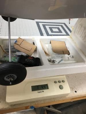
When I plopped the Cub on the balancing stand, it was nose heavy, requiring an ounce and a half on the tail. Here is the weight of the model after balancing.
At this weight, I'll have 102 W/lb available at take off.
Let's fly!
Installing the aileron servo.
Here, the servo rails have been epoxied to the underside of the wing.
I secured one aileron in neutral while I adjusted that servo linkage.
Finished. The arms offset to the front will provide aileron differential.
Testing the power system.
With a 4-cell, 4,500 mAh battery reading 16.6 V, the system drew 46 A and consumed 740 W on a 14 x 8 wood prop.
Setting the control throws.
I used the instructions' recommendations for control throws on low rates and boosted the high rates by 30%. Here I was setting the rudder travel. Oh, and I dialed in plenty of exponential.
Adjusting the weight and balance.
When I plopped the Cub on the balancing stand, it was nose heavy, requiring an ounce and a half on the tail. Here is the weight of the model after balancing.
At this weight, I'll have 102 W/lb available at take off.
Let's fly!
07-27-2022, 02:19 PM
#47
Thread Starter
That things can go wrong when you maiden an airplane in 10- to 15-mph quartering winds gusting to 25-mph or more with clouds threatening to burst at any moment:
1. The model could blow off its stand before you could even insert the battery.
2. Your spotter/back-up pilot/coach could mutter over and over again, �Are you sure you want to do this? Are you really, really sure?�
3. The model, a taildragger, might swerve uncontrollably into the soy beans.
4. Assuming it survived take-off, your Cub could flounder around the sky like a kite because of its possibly low wing loading, the one thing you forgot to calculate.
5. Your model could stall five feet above the runway because an errant gust blew from behind.
6. You might have to turn the clubhouse upside down to find a trash bag big enough for the pieces.
Thankfully, none of the above happened although the weather was exactly as I described.
The Cub taxied well and responded to the rudder flawlessly during take-off. It took only a few clicks of right aileron to fly straight and level. And landing was drama free. There were only four drops of rain on the wing.
Besides learning that the Flitfire Cub would actually fly, I also discovered that it could handle gusty conditions. While I would have preferred a moderate, steady breeze aligned perfectly with the runway, I came away satisfied with this model�s performance.
Sorry, no pictures. Besides, the model is fairly ugly at this stage, with a white cowl, cloudy windshield, and no markings whatsoever.
From this point on, I�m going to work on detailing the Cub during pauses in other projects. Thank you for following along, and I hope you will check back occasionally for updates.
07-29-2022, 07:57 AM
#48
Thread Starter
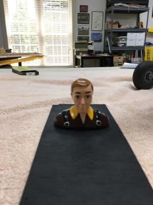
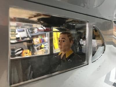
He only lost 1 3/8 inches of full-scale height during the operation to keep his head from interfering with the aileron pushrods. That's right, when I reinstalled the rear faux cockpit floor and fastened the wing on, the rods rubbed up against his precision-cut ginger hairdo.
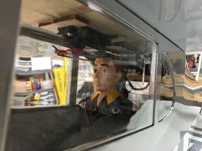
As shown here.
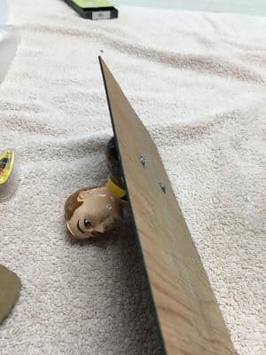
At this point I was relieved that I had screwed, rather than glued,Shorty the pilot onto the floor. It took only a few minutes to remove the floor, free the pilot, trim 1/4" off his upper torso, refasten him, and reinstall the floor. Now there's plenty of clearance.
As shown here.
As shown here.
At this point I was relieved that I had screwed, rather than glued,
As shown here.
07-30-2022, 01:56 PM
#50
Thread Starter
Cliff,
Thank you very much. I did enjoy the process. And I hope I will continue to as I finish up the final details.
I flew the Cub for a little over three minutes during the initial flight. I probably used more throttle than necessary, given the weather and my nervousness. We checked the battery after landing and had used only 30%. With a 4,500 mAh 4-cell LiPo, I expect to achieve eight- to ten-minute flight times with ease.
Thanks for looking in and commenting.
Take care,
Bren
Last edited by GiantModeler; 07-30-2022 at 01:59 PM.