


Flitfire Cub
 08-04-2022, 11:54 AM
#51

Thread Starter
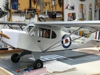
While glued dried on another project, I dragged the Flitfire out to put some markings on.
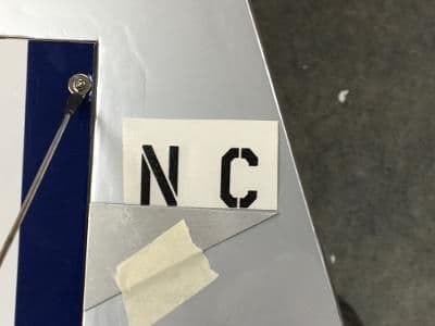
First, an extra-large thank you to my friend, Greg, who found the fonts, designed the layout, and cut the vinyl. He jumped in with both feet to help when he found out this effort was to accumulate food and money to pass on to Second Harvest Food Bank of Northwest North Carolina.
Speaking of which, the raffle for this beast will occur September 10 during the Hobby Park RC Aircraft Club annual Winston-Salem Miniature Air Show. We can only sell tickets the day of the raffle, so you need to be there to buy them. But you need not be present to win. We will get the Flitfire to you.
You probably use the same method I do to install vinyl markings, but I’ll run through it anyway, assisted by pictures.
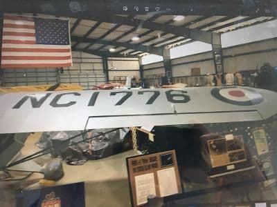
Here are the wing markings on the full-scale Flitfire at the NC Aviation museum.
First, thoroughly clean the area where the markings will end up. I use Windex followed by a solvent if necessary.
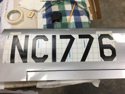
Next, position the vinyl with the carrier still attached. I usually use masking tape and make registration marks on both it and the transfer tape on the decal.
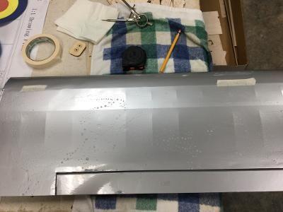
Spray and smear the area with a soapy solution. Again, I use Windex here.
Remove the carrier from the vinyl, not the other way around. That is, keep the transfer tape on your workbench and peel the carrier upward. This way, your markings stay flat.
Now, if you haven’t taken a two-hour nap, the application area should still be wet. Carefully line up the registration marks you made previously and gently lay the decal sheet on the surface. If you miss by a little, the soapy solution will allow you to reposition the marking easily.

Once satisfied with the placement of the markings, rub them through the transfer tape. I use a wadded paper towel to squeeze as much liquid out as I can at this stage. Now take a 20- to 30-minute break.
Gently lift one corner of the transfer tape and fold it over on itself. With one hand, pull the transfer tape while using a paper towel to sop up the inevitable extra liquid. Because you waited a little bit, the vinyl should have started adhering to the surface. If the decal does lift, you can just hold it down with the paper towel. As long as you keep pulling the transfer tape parallel to the surface, no harm will come.
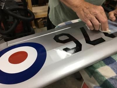
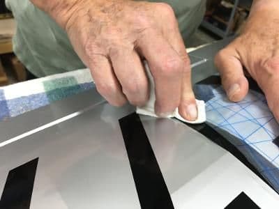
Here I am simultaneously peeling the transfer tape and wiping the "1" in the registration markings. One thing's for certain: I'll never be a hand model.
Once you have removed all the transfer tape, use a paper towel to move as much liquid from under the markings as you can. I do not recommend using a squeegee, even one made from balsa, because it tends to cause gouges, especially on plastic coated balsa.
Most of the time, this process leaves so few and such tiny bubbles they are unnoticeable from a few feet away. If an unsightly blister still remains, lance it with a fine sewing needle and wipe away the liquid with another paper towel.

The Flitfire is one step closer to completion.
If you have a method that you think produces better results, please share it with us. That’s what these forums are about, isn’t it?
First, an extra-large thank you to my friend, Greg, who found the fonts, designed the layout, and cut the vinyl. He jumped in with both feet to help when he found out this effort was to accumulate food and money to pass on to Second Harvest Food Bank of Northwest North Carolina.
Speaking of which, the raffle for this beast will occur September 10 during the Hobby Park RC Aircraft Club annual Winston-Salem Miniature Air Show. We can only sell tickets the day of the raffle, so you need to be there to buy them. But you need not be present to win. We will get the Flitfire to you.
You probably use the same method I do to install vinyl markings, but I’ll run through it anyway, assisted by pictures.
Here are the wing markings on the full-scale Flitfire at the NC Aviation museum.
First, thoroughly clean the area where the markings will end up. I use Windex followed by a solvent if necessary.
Next, position the vinyl with the carrier still attached. I usually use masking tape and make registration marks on both it and the transfer tape on the decal.
Spray and smear the area with a soapy solution. Again, I use Windex here.
Remove the carrier from the vinyl, not the other way around. That is, keep the transfer tape on your workbench and peel the carrier upward. This way, your markings stay flat.
Now, if you haven’t taken a two-hour nap, the application area should still be wet. Carefully line up the registration marks you made previously and gently lay the decal sheet on the surface. If you miss by a little, the soapy solution will allow you to reposition the marking easily.
Once satisfied with the placement of the markings, rub them through the transfer tape. I use a wadded paper towel to squeeze as much liquid out as I can at this stage. Now take a 20- to 30-minute break.
Gently lift one corner of the transfer tape and fold it over on itself. With one hand, pull the transfer tape while using a paper towel to sop up the inevitable extra liquid. Because you waited a little bit, the vinyl should have started adhering to the surface. If the decal does lift, you can just hold it down with the paper towel. As long as you keep pulling the transfer tape parallel to the surface, no harm will come.
Here I am simultaneously peeling the transfer tape and wiping the "1" in the registration markings. One thing's for certain: I'll never be a hand model.
Once you have removed all the transfer tape, use a paper towel to move as much liquid from under the markings as you can. I do not recommend using a squeegee, even one made from balsa, because it tends to cause gouges, especially on plastic coated balsa.
Most of the time, this process leaves so few and such tiny bubbles they are unnoticeable from a few feet away. If an unsightly blister still remains, lance it with a fine sewing needle and wipe away the liquid with another paper towel.
The Flitfire is one step closer to completion.
If you have a method that you think produces better results, please share it with us. That’s what these forums are about, isn’t it?
Last edited by GiantModeler; 08-05-2022 at 09:14 AM. Reason: Spelling and grammar
 08-10-2022, 10:25 AM
#52
Thread Starter
Before I start on this post, please allow me to say this: None of the ideas or techniques below originated with me. I picked them up over the years from this and other RC forums. While I don�t remember who first thought them up, I would credit those innovators in a heartbeat if I did.
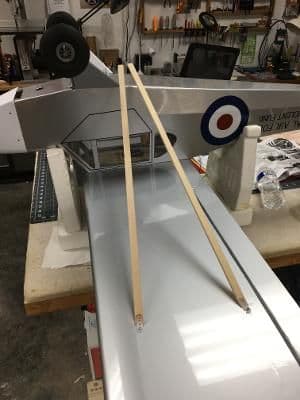
Even though I selected what I thought was the strongest balsa for the horizontal stabilizer trailing edge, it turned out rather bendy, in my opinion. Combining that with the fact that I added 1.5 ounces of useless weight to the tail to achieve the proper CG, I decided to fabricate and install tail braces.
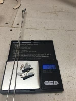
I gathered up some scrap 2-56 threaded pushrods. (You accumulate plenty if you assemble many ARFs for electric rather than gas or glow.) I placed them and other bracing components on a scale and found they weighed only an ounce, less than the easily removeable useless weight under the stab.
The plans showed me where to drill the holes for #2 hardware in the stab and fin. I made a SWAG at the hole placement in the fuselage.
For stab attachment, I used small, steel landing gear straps, bent to the appropriate angles. These I fastened with #2 nuts and bolts through the stab trailing edge.
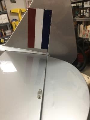
If you look closely, you might be able to see the hole drilled in the fin for brace attachment.
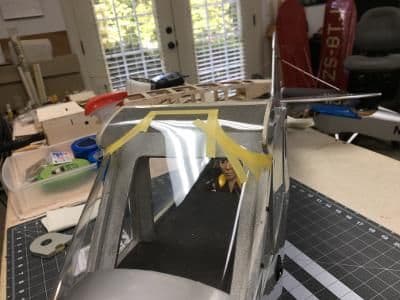
I screwed a clevis to one end of a pushrod and attached the combo to an LG strap. Then I trimmed the rod to fit between the stab and fin. After removing the rod, I silver soldered a small electrical ring terminal on the unthreaded end. After it cooled, I shrunk a black tube around the joint, another technique I picked up reading posts on this and other RC forums.
Once reinstalled onto the model, the brace can be adjusted at the clevis end. I try to snug it up just enough to prevent it from rattling. Any more, and you risk misaligning the tail group that you spent much time trying to get �just right.�
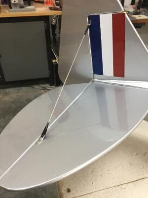
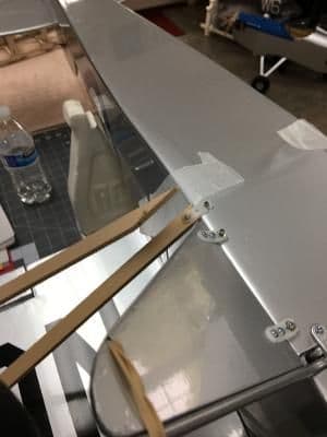
Here's the right upper brace, installed and tensioned.
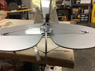
The lower braces in place.
The tail braces contribute much strength and stability to the tail feathers. And I'll be able to remove at least two of those useless 1/2 ounce weights.
Even though I selected what I thought was the strongest balsa for the horizontal stabilizer trailing edge, it turned out rather bendy, in my opinion. Combining that with the fact that I added 1.5 ounces of useless weight to the tail to achieve the proper CG, I decided to fabricate and install tail braces.
I gathered up some scrap 2-56 threaded pushrods. (You accumulate plenty if you assemble many ARFs for electric rather than gas or glow.) I placed them and other bracing components on a scale and found they weighed only an ounce, less than the easily removeable useless weight under the stab.
The plans showed me where to drill the holes for #2 hardware in the stab and fin. I made a SWAG at the hole placement in the fuselage.
For stab attachment, I used small, steel landing gear straps, bent to the appropriate angles. These I fastened with #2 nuts and bolts through the stab trailing edge.
If you look closely, you might be able to see the hole drilled in the fin for brace attachment.
I screwed a clevis to one end of a pushrod and attached the combo to an LG strap. Then I trimmed the rod to fit between the stab and fin. After removing the rod, I silver soldered a small electrical ring terminal on the unthreaded end. After it cooled, I shrunk a black tube around the joint, another technique I picked up reading posts on this and other RC forums.
Once reinstalled onto the model, the brace can be adjusted at the clevis end. I try to snug it up just enough to prevent it from rattling. Any more, and you risk misaligning the tail group that you spent much time trying to get �just right.�
Here's the right upper brace, installed and tensioned.
The lower braces in place.
The tail braces contribute much strength and stability to the tail feathers. And I'll be able to remove at least two of those useless 1/2 ounce weights.
08-11-2022, 05:10 AM
#54
Thread Starter
Thank you very much. I want whoever wins this model to know it was put together right.
You are correct about the heat-shrink tubing. These particular solder joints turned out OK, aesthetically. But that's not always the case. The tubing hides flaws and I believe that flat black calls less attention to itself than shiny, lumpy solder.
Take care,
Bren
You are correct about the heat-shrink tubing. These particular solder joints turned out OK, aesthetically. But that's not always the case. The tubing hides flaws and I believe that flat black calls less attention to itself than shiny, lumpy solder.
Take care,
Bren
08-15-2022, 09:13 AM
#55
Thread Starter
During a break in another project, I dug out the Flitfire fuselage to create a door outline. This kit did not provide for an actual door, so an outline will have to do.
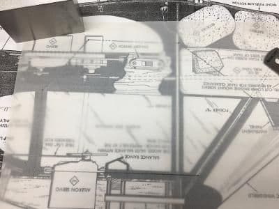
First up, I found and unrolled the plans one more time. Then I copied the outline on tracing paper.
This I taped to the right side of the fuselage and . . .
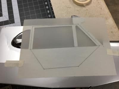
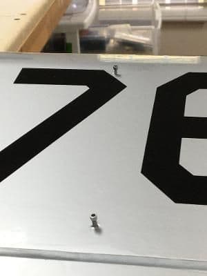
poked a hole through each line intersection. If you squint, you should be able to see the pin holes.
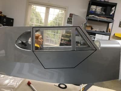
It was simple to connect the dots with 1/16" flat black chart tape. That translates to about a 3/8" gap on the full scale.
First up, I found and unrolled the plans one more time. Then I copied the outline on tracing paper.
This I taped to the right side of the fuselage and . . .
poked a hole through each line intersection. If you squint, you should be able to see the pin holes.
It was simple to connect the dots with 1/16" flat black chart tape. That translates to about a 3/8" gap on the full scale.
Last edited by GiantModeler; 08-15-2022 at 09:17 AM. Reason: Auto editor did not like a particular word
08-16-2022, 12:55 PM
#56
Thread Starter
Does anyone know what you call the covering over the triangular landing gear struts on a full-scale Piper Cub? I don't either. But when I look at them, all I can think of is "spats," the covers gentlemen wore over their shoes in the late 19th and early 20th centuries. So, that is what I shall call the parts I added to the Flitfire yesterday.
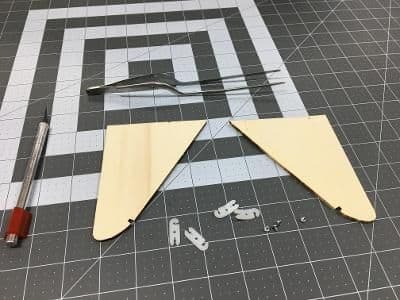
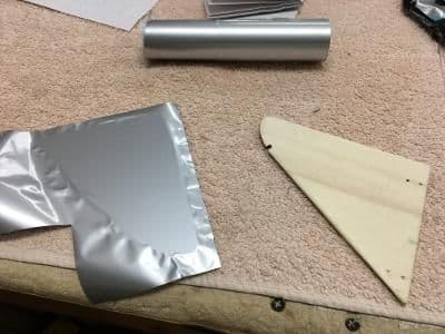
The Goldberg kit provided two laser-cut pieces of 1/8" plywood for the basis of the spats. Also included were were nylon brackets and itty-bitty wood screws (#2 x 3/16").
Wow! I have no idea why this photo is so big, but I like it because it shows details so clearly.
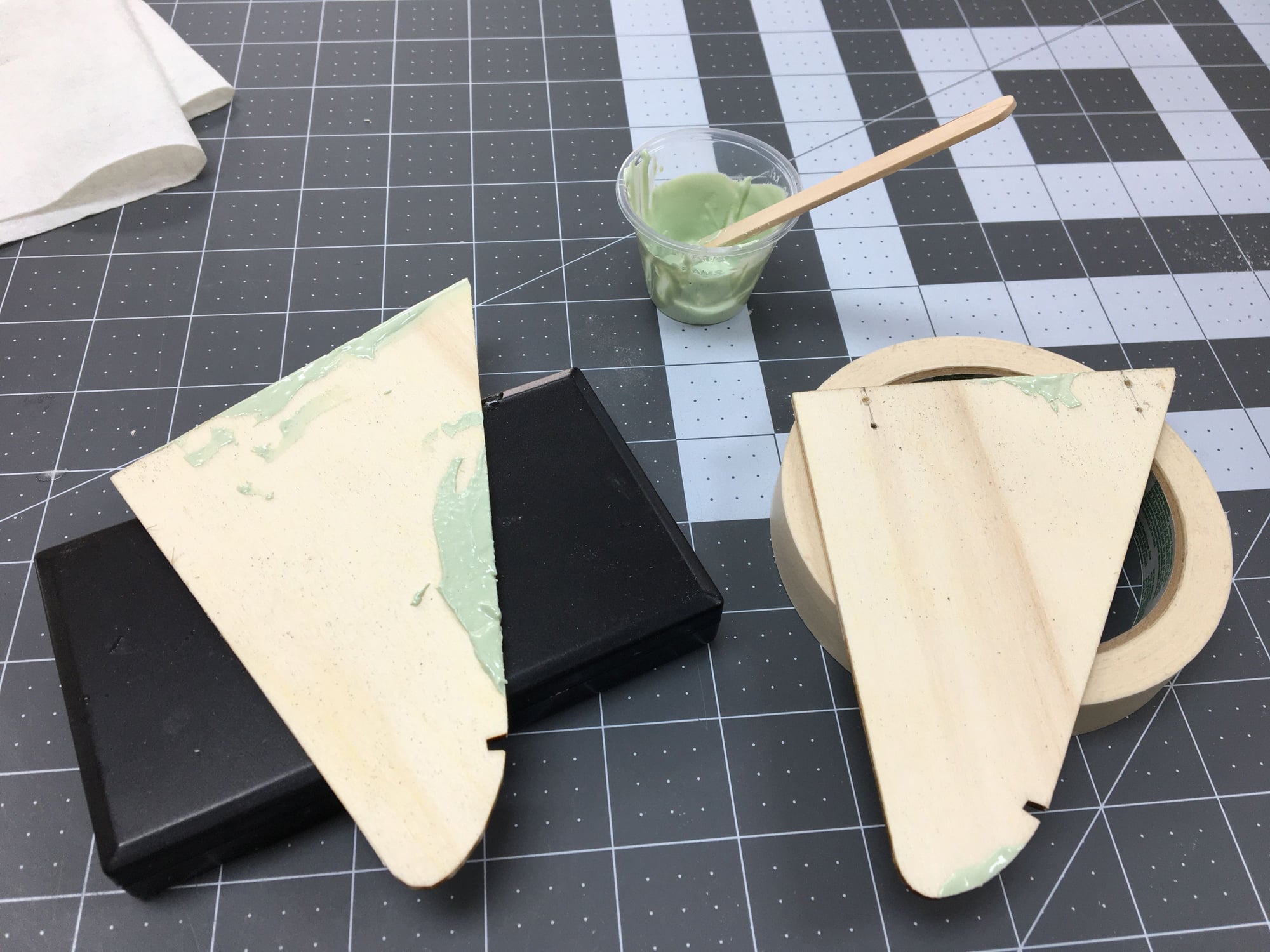
Anyway, because I incorrectly removed these pieces from their surrounding sheets, there were some pits to repair. Here they are filled with Dolphin Glaze.
Back to normal size. After sanding the glaze down, I covered the spats with the same material I used on the rest of the Flitfire: Ultracote Silver. This covering is especially easy to use on flat surfaces. You just start ironing from the middle out and get perfect results every time.
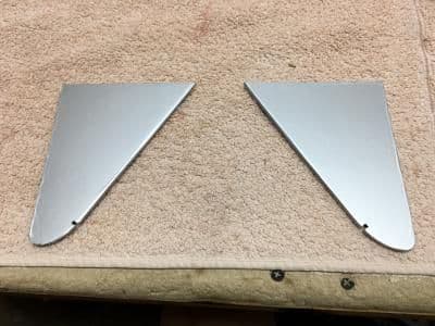
Here, both spats have been covered and await . . .
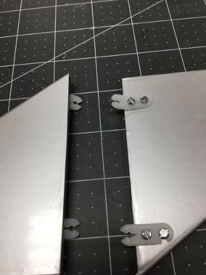
installation of brackets.
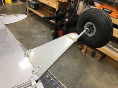
Next, I fastened the spats to the fuselage with self-tapping screws and to the landing gear wire with a rubber band, per instructions. I hope to replace the rubber bands with silver stretch cord before the raffle.
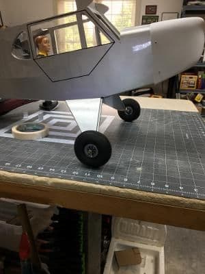
The final result.
The Goldberg kit provided two laser-cut pieces of 1/8" plywood for the basis of the spats. Also included were were nylon brackets and itty-bitty wood screws (#2 x 3/16").
Wow! I have no idea why this photo is so big, but I like it because it shows details so clearly.
Anyway, because I incorrectly removed these pieces from their surrounding sheets, there were some pits to repair. Here they are filled with Dolphin Glaze.
Back to normal size. After sanding the glaze down, I covered the spats with the same material I used on the rest of the Flitfire: Ultracote Silver. This covering is especially easy to use on flat surfaces. You just start ironing from the middle out and get perfect results every time.
Here, both spats have been covered and await . . .
installation of brackets.
Next, I fastened the spats to the fuselage with self-tapping screws and to the landing gear wire with a rubber band, per instructions. I hope to replace the rubber bands with silver stretch cord before the raffle.
The final result.
Last edited by GiantModeler; 08-16-2022 at 12:59 PM. Reason: Correct punctuation
09-03-2022, 04:25 PM
#57
Thread Starter
The Flitfire raffle is only a week away and there's still a checklist of mini projects to finish before the model is ready for its new owner.
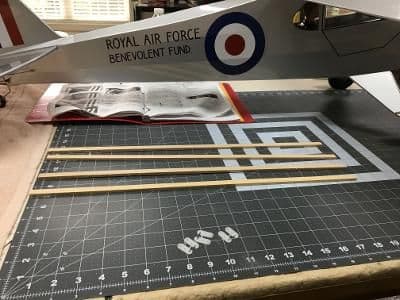
The wing struts are not necessary to locate or support the wing. Some even recommend not flying a Goldberg Cub with the non-functional struts in place. Regardless, even a sport scale model deserves them. Here are the components supplied with the kit.
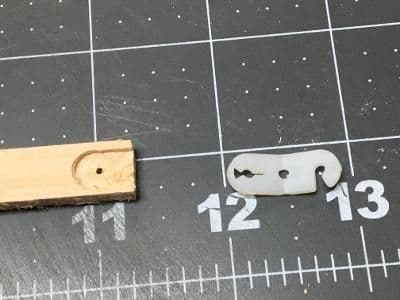
First, I cur grooves in the basswood stick ends with a 5/16" milling bit in a drill press. This could also be done with a hobby knife.
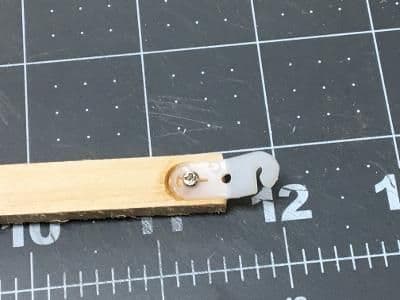
Here, I have fastened a nylon snap bracket with a tiny screw and thick CA. I did this for four sticks.
Then I installed #2 x 1/2" self-tapping screws at the anchor points, Here two wing screws are shown.
I attached two of the sticks to a pair of wing anchors and let them rest against the bottom of the fuselage just behind the LG spats.
Here, I have trimmed the rear stick to butt up against the front one.
I glued them together and installed a snap bracket on the joined end.
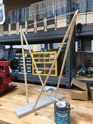
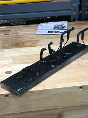
After rounding the sticks' edges, I brushed on two coats of WBPU, fine sanded them, and fastened them to this improvised painting fixture.
The prepped struts visited the spray booth for a coat of silver rattle can paint. Snapped onto the Flitfire, this is what they looked like.
You probably noticed the missing windshield. That's next on the checklist.
The wing struts are not necessary to locate or support the wing. Some even recommend not flying a Goldberg Cub with the non-functional struts in place. Regardless, even a sport scale model deserves them. Here are the components supplied with the kit.
First, I cur grooves in the basswood stick ends with a 5/16" milling bit in a drill press. This could also be done with a hobby knife.
Here, I have fastened a nylon snap bracket with a tiny screw and thick CA. I did this for four sticks.
Then I installed #2 x 1/2" self-tapping screws at the anchor points, Here two wing screws are shown.
I attached two of the sticks to a pair of wing anchors and let them rest against the bottom of the fuselage just behind the LG spats.
Here, I have trimmed the rear stick to butt up against the front one.
I glued them together and installed a snap bracket on the joined end.
After rounding the sticks' edges, I brushed on two coats of WBPU, fine sanded them, and fastened them to this improvised painting fixture.
The prepped struts visited the spray booth for a coat of silver rattle can paint. Snapped onto the Flitfire, this is what they looked like.
You probably noticed the missing windshield. That's next on the checklist.
09-04-2022, 02:36 AM
#58

............
The wing struts are not necessary to locate or support the wing. Some even recommend not flying a Goldberg Cub with the non-functional struts in place. Regardless, even a sport scale model deserves them...........
.............. Snapped onto the Flitfire, this is what they looked like.
You probably noticed the missing windshield. That's next on the checklist.
getting close now..
 09-04-2022, 11:40 AM
#60
Thread Starter
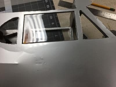
As provided in the kit, the windshield fit to the fuselage was remarkably good. However, it did not look like the one in the full-scale Flitfire. To transform it, I had to paint it twice.
To do this, I masked the outline of the wing junction with Tamiya tape.
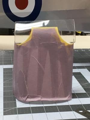
Then filled in the front . . .
and back with painter's tape.
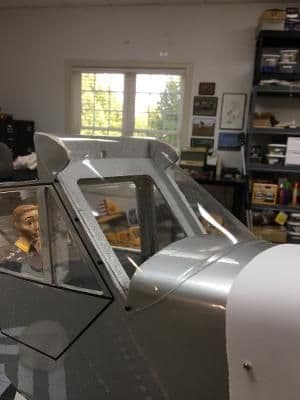
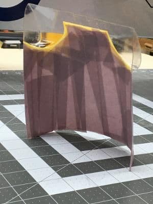
After at trip to the spray booth for several coats of rattle-can silver paint and a 24-hour curing period, it was time to retape the front of the windshield. Early Cubs had three-piece windshields with flanged joints. So did the Flitfire. Here the top, bottom, and side outlines have been defined with Tamiya tape.
In this photo, everything has been taped up, leaving only the joint lines available for paint. Fiddly stuff, indeed.
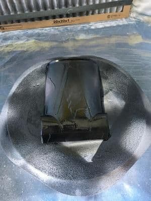
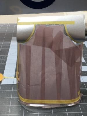
I applied satin black paint, rattle-can again, and ended up with this ugly duckling.
Which transformed into a reasonably accurate Cub windshield after unmasking.
Six days to go until the raffle.
Next up, a new dashboard.
09-05-2022, 09:59 AM
#61
Thread Starter
Before showing how the instrument panel went together, I want to acknowledge that the ideas behind it did not originate with me, but with fellow modeler Alan Yendle (AlanDY on this forum) who posts prolifically on RCScaleBuilder.com (under the user name Alan). He has more creative ideas about RC model building than I thought could fit in one person's head. And he is willing to share them with all of us.
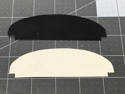
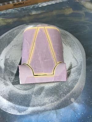
First, I cut a trial-and-error pattern from a 3 x 5 card. After transferring the pattern to litho plate, I scored it with a box cutter and carefully folded each score until it snapped. The black side survived this process without a scratch, so I didn't even have to paint it.
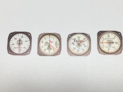
I located some photos of actual Cub instruments online and imported them to a Word document, adjusting their size to approximate 1/5.5 scale, These I printed on glossy photo paper.
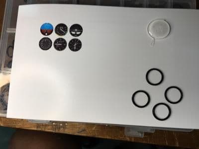
Here's where Alan's magic comes in. To create 3D bezels, he uses O-rings. A multi-size set of these are available at Amazon for around $12 ( ), The photo above shows them, along with a pool of E6000 adhesive. I ended up not using the instruments shown once I found more authentic ones.
After gluing the O-rings around the instrument photos, I trimmed the excess with a hobby knife, leaving only dials and bezels.
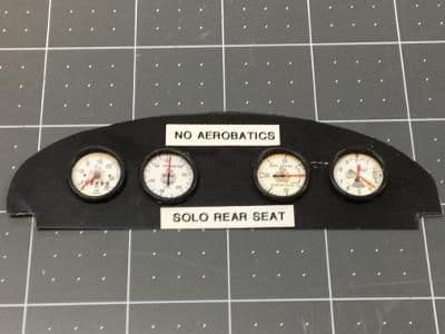
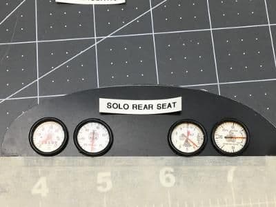
I fastened the dummy gauges with a dab of E6000 on each. The warning placards came from a label maker.
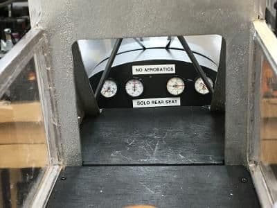
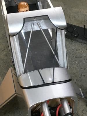
Here's a pilot's view of the finished panel.
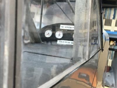
And a view through the side windows.
Five days to go.
Next up, the dummy engine. (If I can find my "Dummy Engines for Dummies" book.)
First, I cut a trial-and-error pattern from a 3 x 5 card. After transferring the pattern to litho plate, I scored it with a box cutter and carefully folded each score until it snapped. The black side survived this process without a scratch, so I didn't even have to paint it.
I located some photos of actual Cub instruments online and imported them to a Word document, adjusting their size to approximate 1/5.5 scale, These I printed on glossy photo paper.
Here's where Alan's magic comes in. To create 3D bezels, he uses O-rings. A multi-size set of these are available at Amazon for around $12 ( ), The photo above shows them, along with a pool of E6000 adhesive. I ended up not using the instruments shown once I found more authentic ones.
After gluing the O-rings around the instrument photos, I trimmed the excess with a hobby knife, leaving only dials and bezels.
I fastened the dummy gauges with a dab of E6000 on each. The warning placards came from a label maker.
Here's a pilot's view of the finished panel.
And a view through the side windows.
Five days to go.
Next up, the dummy engine. (If I can find my "Dummy Engines for Dummies" book.)
09-06-2022, 05:01 PM
#62
Thread Starter
Early in this build, a friend of mine, Greg Gee, 3D printed a Continental engine kit for this project. At 1/5.5 scale, it would fit the Flitfire perfectly. Unfortunately, the full-scale carried a Franklin. Fortunately, it's finished in flat black and looks enough like a Continental that I don't think anyone will notice.
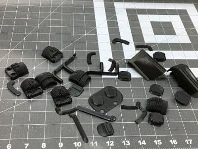
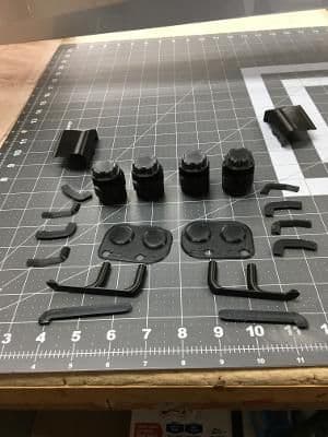
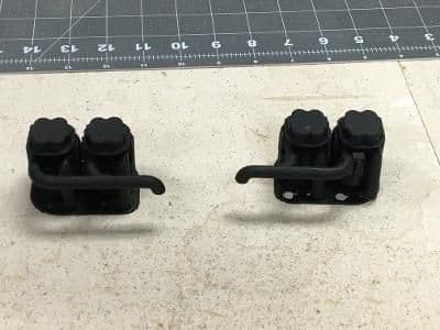
Here's the kit.
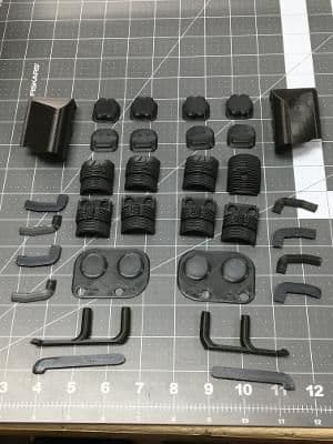
Here's the same kit, organized. Greg printed the pieces in black PLA from a scalable public domain design.
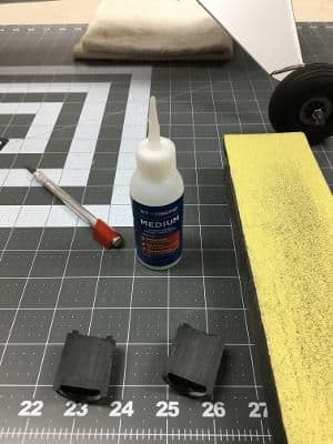
I started with the cylinders, sanding the flat areas to improve adhesion.
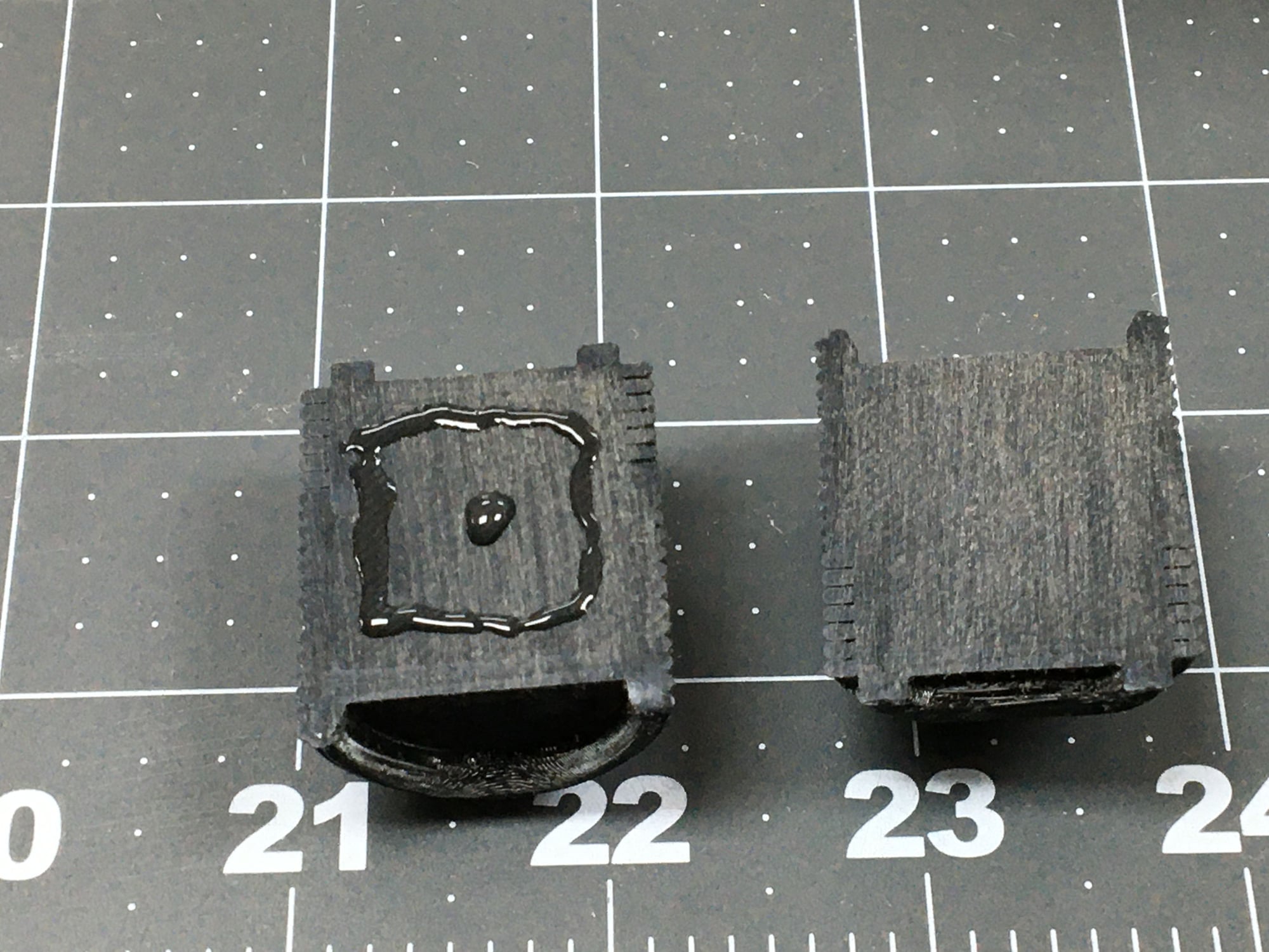
I used medium CA here, as well as between all the flat surfaces.
The number of parts shrunk as the glue flowed.
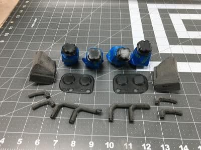
Before completing the assemblies, I prepped them for painting in different black finishes. Here, the intake and exhaust pipes are ready for flat black.
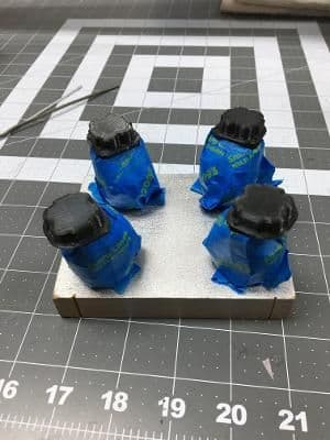
I decided to leave the cylinders in their unpainted printed finish, a semi-gloss black and paint the valve covers flat. I hoped that having contrasting finishes might help the engine's appearance.
Painted and fully assembled, here are two banks of dummy cylinders. I glued the intake and exhaust pipes to the cylinders with CA gel.
Four days to go.
Now, to fasten the cylinders to the cowl.
Here's the kit.
Here's the same kit, organized. Greg printed the pieces in black PLA from a scalable public domain design.
I started with the cylinders, sanding the flat areas to improve adhesion.
I used medium CA here, as well as between all the flat surfaces.
The number of parts shrunk as the glue flowed.
Before completing the assemblies, I prepped them for painting in different black finishes. Here, the intake and exhaust pipes are ready for flat black.
I decided to leave the cylinders in their unpainted printed finish, a semi-gloss black and paint the valve covers flat. I hoped that having contrasting finishes might help the engine's appearance.
Painted and fully assembled, here are two banks of dummy cylinders. I glued the intake and exhaust pipes to the cylinders with CA gel.
Four days to go.
Now, to fasten the cylinders to the cowl.
09-07-2022, 02:37 PM
#63
Thread Starter
Because I had chosen a motor on the high side of the acceptable range (a Power 46 I had on hand), there wasn't enough room inside the cowl to fabricate shadow boxes to accept the entire cylinder pairs. Therefore, I had to figure out a way to install the dummy motor onto the cowl's exterior.
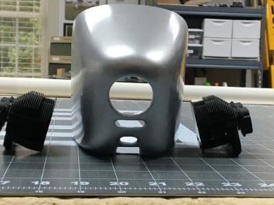
Here's what I had to work with: a painted cowl and two pairs of cylinders.
To start, I located the output center line with a laser level. I did this on the right side as well. Then I added several other horizontal strips of masking tape in an effort to protect the cowl's finish from the trial and error that would ensue.

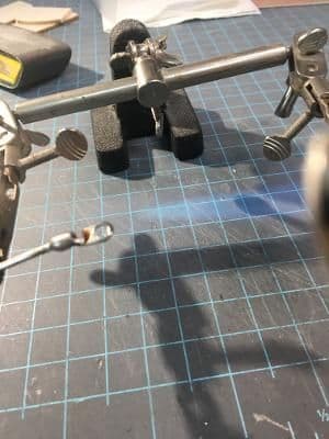
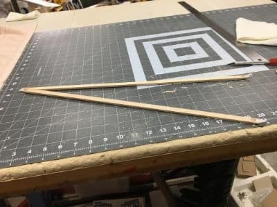
This is the jig I used during the process. The space between the triangles is the scale distance between valve covers on a Continental engine. I needed to get a partial cylinder bank to fit against the cowl and a triangle simultaneously. From this point forward, frustration trumped photography, so what follows is more words than pictures.
First, I sliced a wedge from a cylinder bank with a band saw. I chose points at the front and back of the bank that should, in my estimation, contact the cowl, leaving plenty of material in between for grinding.
As luck would have it, I had recently purchased an oscillating spindle sander at a 20% off Harbor Freight sale. Using the largest sanding cylinder, I gradually removed material from between my reference points. By gradually, I mean I moved countless times between the sander and the jig until I got a reasonable fit between the cylinder bank and the cowl. Now, it's only about 10 feet between the sander and my building bench. I bet I walked more than a half mile while sanding both banks. But, without that sander, I'd still be scratching my head.
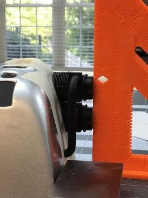
When I finally got the fit I wanted, I did remember to get a picture. Here, the valve covers are just touching the triangle's vertical edge which is parallel to the drive center line.
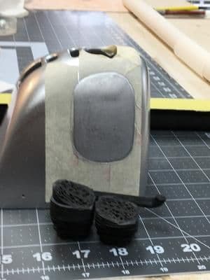
When I got both banks to fit in the jig, it was time to glue. Here I have cut an oblong shape in the masking tape and removed the center. It was large enough to accommodate the two cylinders and intake pipes with about a 1/8" margin. I scuffed the cowl paint with sandpaper. The cylinder bank needed no scuffing, having encountered the spindle sander on and off for over an hour.
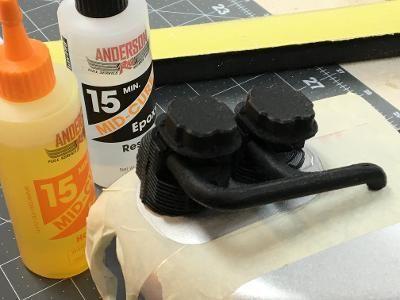
I used 15-minute epoxy to fasten the left cylinder bank to the cowl. I mixed enough to fill the tiny gaps that still remained after shaping.
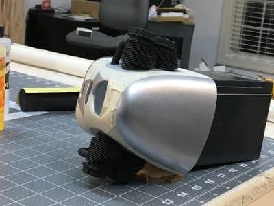
A couple of hours later, I did the same for the right bank.
Three days to go.
Next, engine cosmetics, as in eyebrows.
Here's what I had to work with: a painted cowl and two pairs of cylinders.
To start, I located the output center line with a laser level. I did this on the right side as well. Then I added several other horizontal strips of masking tape in an effort to protect the cowl's finish from the trial and error that would ensue.
This is the jig I used during the process. The space between the triangles is the scale distance between valve covers on a Continental engine. I needed to get a partial cylinder bank to fit against the cowl and a triangle simultaneously. From this point forward, frustration trumped photography, so what follows is more words than pictures.
First, I sliced a wedge from a cylinder bank with a band saw. I chose points at the front and back of the bank that should, in my estimation, contact the cowl, leaving plenty of material in between for grinding.
As luck would have it, I had recently purchased an oscillating spindle sander at a 20% off Harbor Freight sale. Using the largest sanding cylinder, I gradually removed material from between my reference points. By gradually, I mean I moved countless times between the sander and the jig until I got a reasonable fit between the cylinder bank and the cowl. Now, it's only about 10 feet between the sander and my building bench. I bet I walked more than a half mile while sanding both banks. But, without that sander, I'd still be scratching my head.
When I finally got the fit I wanted, I did remember to get a picture. Here, the valve covers are just touching the triangle's vertical edge which is parallel to the drive center line.
When I got both banks to fit in the jig, it was time to glue. Here I have cut an oblong shape in the masking tape and removed the center. It was large enough to accommodate the two cylinders and intake pipes with about a 1/8" margin. I scuffed the cowl paint with sandpaper. The cylinder bank needed no scuffing, having encountered the spindle sander on and off for over an hour.
I used 15-minute epoxy to fasten the left cylinder bank to the cowl. I mixed enough to fill the tiny gaps that still remained after shaping.
A couple of hours later, I did the same for the right bank.
Three days to go.
Next, engine cosmetics, as in eyebrows.
Last edited by GiantModeler; 09-07-2022 at 02:41 PM. Reason: Corrected punctuation and layout errors
The following users liked this post:
RICKSTUBBZ (09-08-2022)
09-08-2022, 08:43 AM
#64
Thread Starter
The last elements to install on the dummy engine were the air-cooling shrouds, called "eyebrows" by some. They came with the 3D printed kit, but needed to be trimmed to fit against the cowl's exterior.
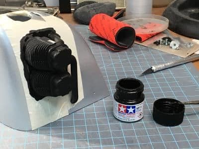
Before cutting, however, I painted the area on the cowl adjacent to the cylinders flat black, using the tape I had installed as a guide as a mask.
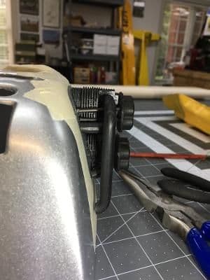
Then, I installed the pushrod tubes. I had previously drilled holes in the underside of the valve platform. For the tubes I used 1/16" wire that had already been painted black.
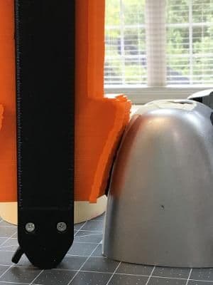
Whereas I shaped the cylinder banks completely by trial and error, I decided to use a different approach for the shrouds. The device shown above is a Super Gauge (TM) designed to copy contours of irregularly shaped objects. Although intended for large, inflexible things, with dexterous manipulation, it can be made to work on small, flimsy items like this cowl. I'm still trying to figure out how I got it to work.
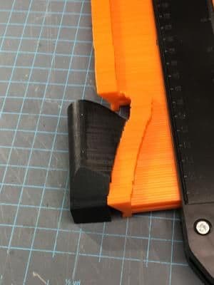
Regardless, I transferred the cowl shape to the shroud and cut along the trace mark with a band saw. It took only one trip to the spindle sander the get a perfect fit.
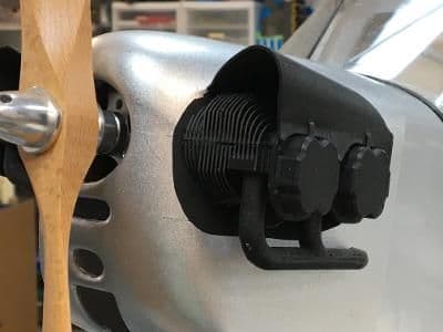
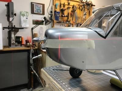
The dummy engine installation was complete. It turned out better than I had anticipated, thanks to that 3D printed kit.
Two days to go.
Before cutting, however, I painted the area on the cowl adjacent to the cylinders flat black, using the tape I had installed as a guide as a mask.
Then, I installed the pushrod tubes. I had previously drilled holes in the underside of the valve platform. For the tubes I used 1/16" wire that had already been painted black.
Whereas I shaped the cylinder banks completely by trial and error, I decided to use a different approach for the shrouds. The device shown above is a Super Gauge (TM) designed to copy contours of irregularly shaped objects. Although intended for large, inflexible things, with dexterous manipulation, it can be made to work on small, flimsy items like this cowl. I'm still trying to figure out how I got it to work.
Regardless, I transferred the cowl shape to the shroud and cut along the trace mark with a band saw. It took only one trip to the spindle sander the get a perfect fit.
The dummy engine installation was complete. It turned out better than I had anticipated, thanks to that 3D printed kit.
Two days to go.
09-08-2022, 11:25 AM
#66
Thread Starter
Rick,
Thank you for your reply. With luck, I'll have those pictures to post tomorrow. And of course, we'll take pictures at the raffle.
Thanks again for following along.
Take care,
Bren
Thank you for your reply. With luck, I'll have those pictures to post tomorrow. And of course, we'll take pictures at the raffle.
Thanks again for following along.
Take care,
Bren
Last edited by GiantModeler; 09-08-2022 at 06:53 PM.
09-09-2022, 02:50 PM
#67
Thread Starter
This build is finally down to just a few finishing touches.
Greg finally found some free fonts that he could modify to sorta match the one's on the full-scale Flitfire's tail. Here, I squared the upper marking to the fin.
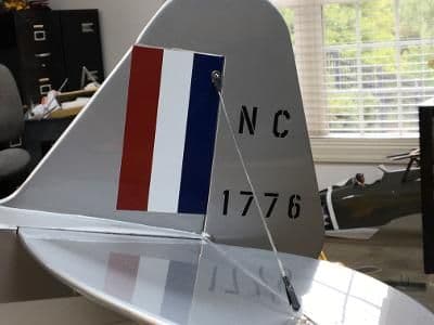
And here they are fully installed.
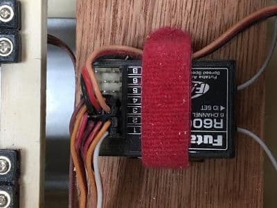
Because the lucky winner might not fly Futaba, I removed this receiver.
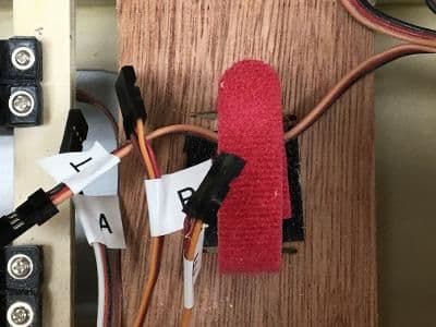
And left the servo leads appropriately tagged. During this operation, I verified that the false floor could be removed and reinstalled, without damage, to service the radio components.
I had one further marking to track down: the Piper plate on the cowl. I located a good image online, moved it into a Word document, and shrank it to the scale size. The picture above shows a prototype, printed on plain paper at low resolution. I believe the final version, printed at max dpi on photo paper, will be even better.
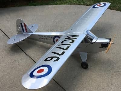
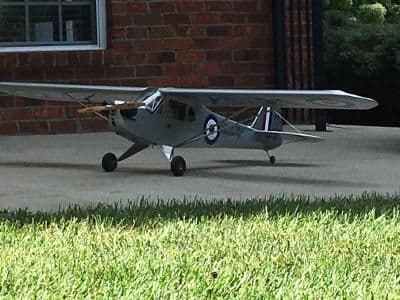
Rick, here are your beauty shots:
Only one day to go until the raffle. Unfortunately, there's a strong forecast for rain.
Please stay tuned, and I'll let you know what happened.
Greg finally found some free fonts that he could modify to sorta match the one's on the full-scale Flitfire's tail. Here, I squared the upper marking to the fin.
And here they are fully installed.
Because the lucky winner might not fly Futaba, I removed this receiver.
And left the servo leads appropriately tagged. During this operation, I verified that the false floor could be removed and reinstalled, without damage, to service the radio components.
I had one further marking to track down: the Piper plate on the cowl. I located a good image online, moved it into a Word document, and shrank it to the scale size. The picture above shows a prototype, printed on plain paper at low resolution. I believe the final version, printed at max dpi on photo paper, will be even better.
Rick, here are your beauty shots:
Only one day to go until the raffle. Unfortunately, there's a strong forecast for rain.
Please stay tuned, and I'll let you know what happened.
09-09-2022, 05:15 PM
#68
Thread Starter
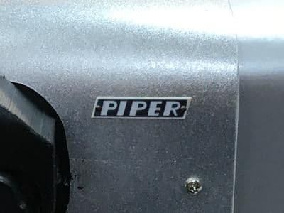
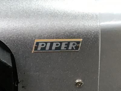
Here's the final version of the Piper emblem on the cowl. It was printed on photo paper at a high resolution, then trimmed to size to eliminate the yellow surrounding it. I fastened it on with double-sided tape.
Still no word on whether the weather will allow us to run the raffle tomorrow.
09-10-2022, 04:54 AM
#69
Thread Starter
A steady drizzle and wave after wave of heavy rain on radar caused us to cancel today's fly in and accompanying raffle.
When to reschedule is under discussion. As soon as a decision is made, I'll post it on this forum.
When to reschedule is under discussion. As soon as a decision is made, I'll post it on this forum.
09-12-2022, 06:36 PM
#70
Thread Starter
The Flitfire raffle has been rescheduled to October 15. We will hold it in conjunction with our annual tailgate swap meet fun fly.
All the collected proceeds, both non-perishable food and money, will be turned over to Second Harvest Food Bank of Northwest North Carolina.
If you plan to travel to central NC that day, please stop by and fly and/or buy.
Take care,
Bren
All the collected proceeds, both non-perishable food and money, will be turned over to Second Harvest Food Bank of Northwest North Carolina.
If you plan to travel to central NC that day, please stop by and fly and/or buy.
Take care,
Bren
10-15-2022, 04:28 PM
#71
Thread Starter
The Flitfire Cub found a new home today.
As the focal point of our annual fundraiser, it helped raise $500 for the Second Harvest Food Bank of Northwest North Carolina. A check for that amount and multiple cans of food will be delivered to the charity early next week.
Thank you for following along as I stumbled through this build.
Take care,
Bren Bailey
The following users liked this post:
khodges (10-22-2022)
