


Moustache 20cc DHC-2 Beaver Build


 10-15-2022, 11:12 PM
#54

Thread Starter
As I stated earlier, this kit did not live up to my expectations and is up there with the most frustrating kits I have ever assembled. Not because it is the absolute worse kit, but because of the promise vs. reality. It is obvious that a prototype was never built prior to production and that the designer has missed many engineering aspects.
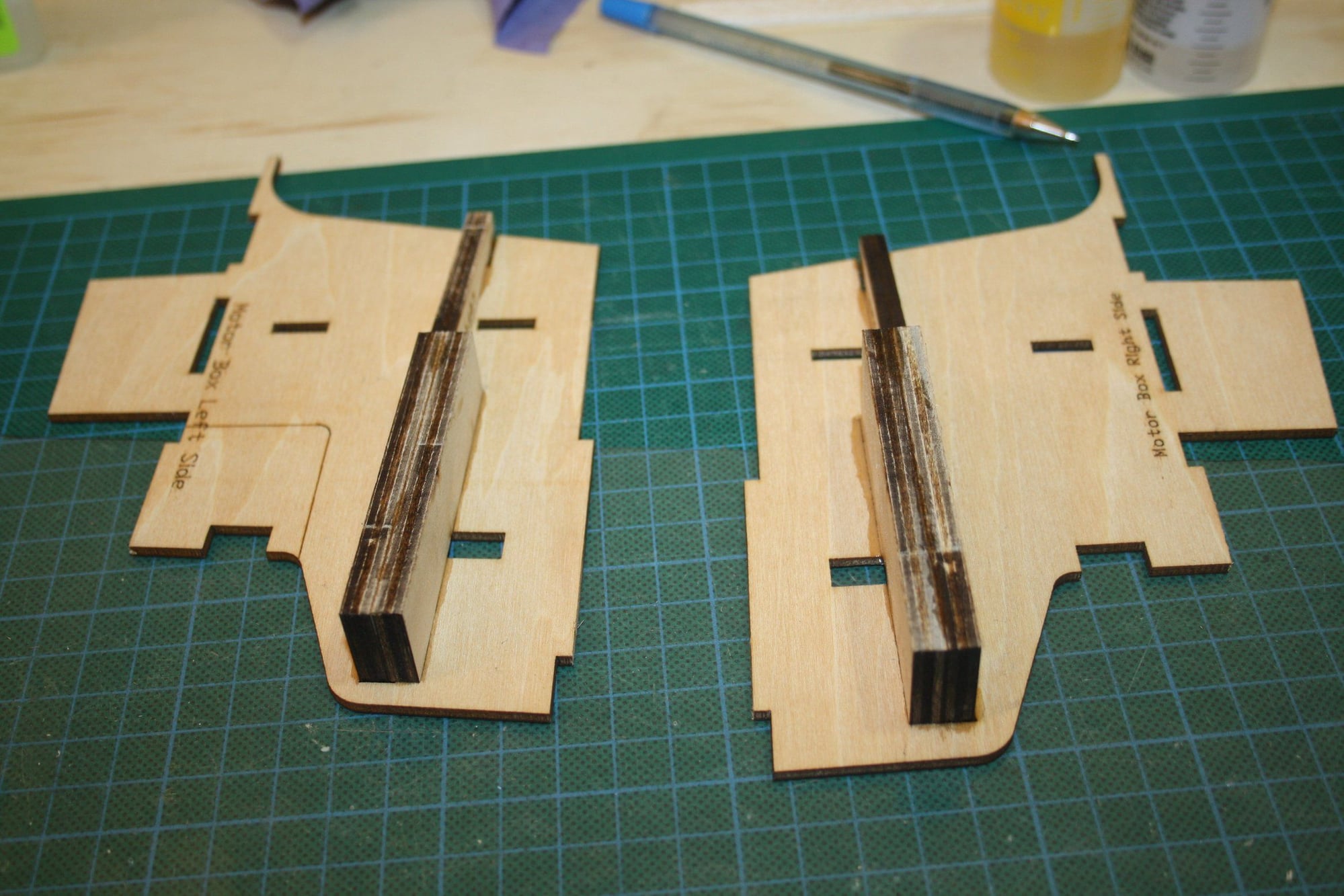
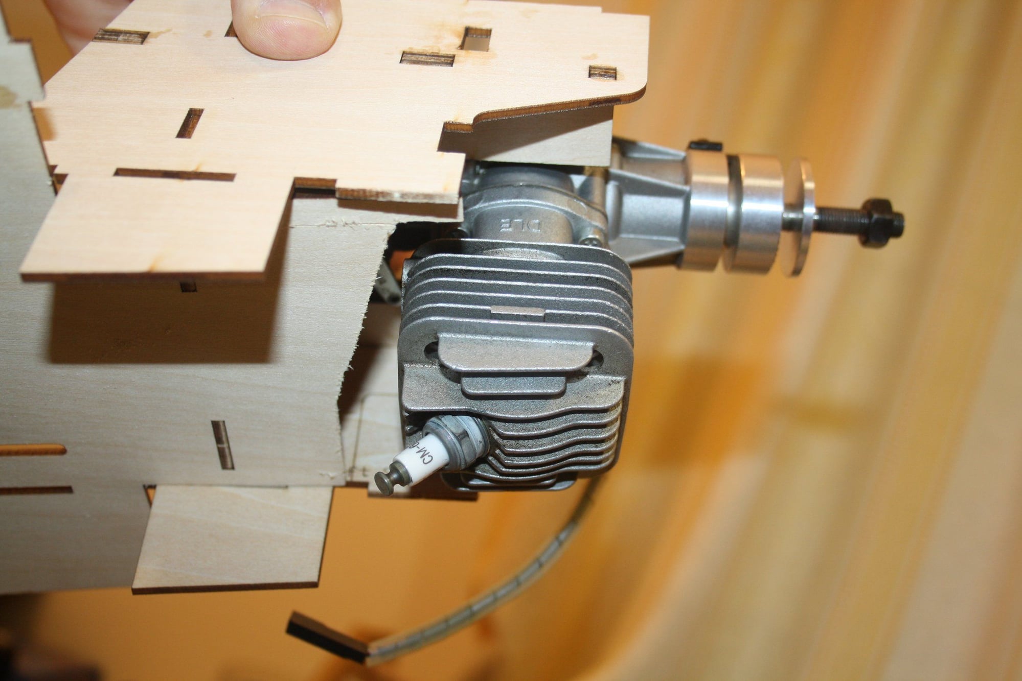
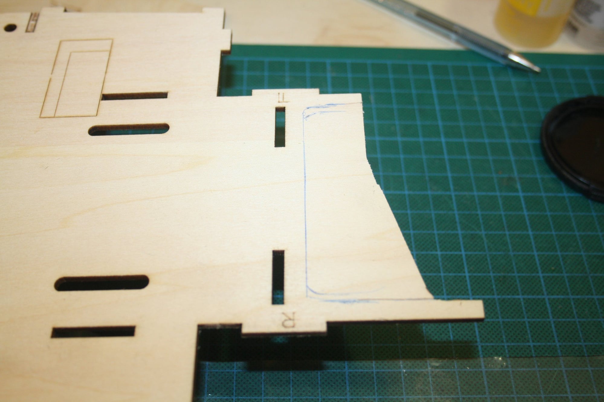
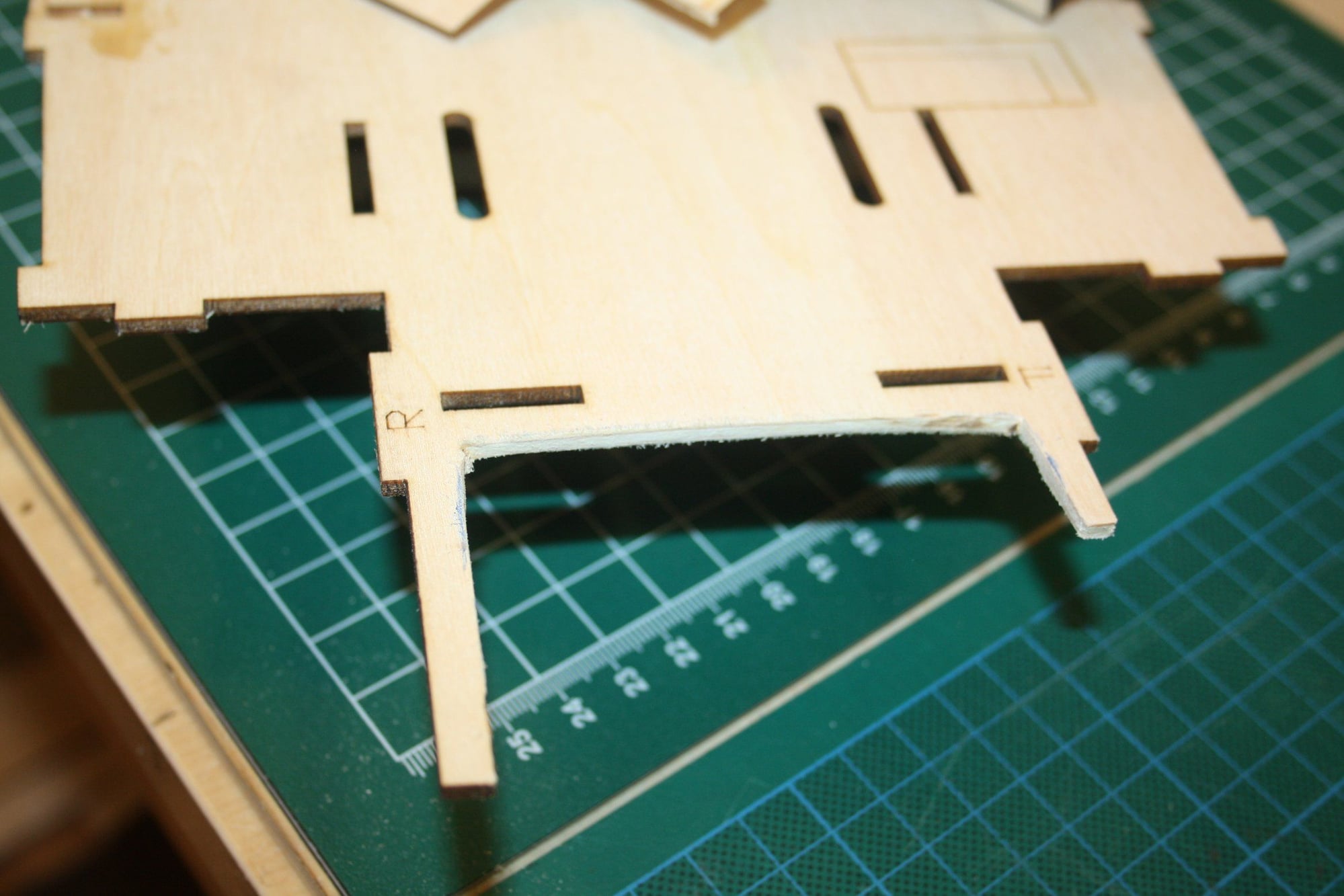
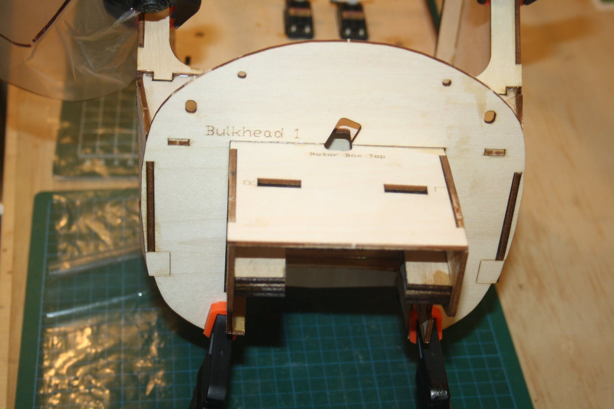
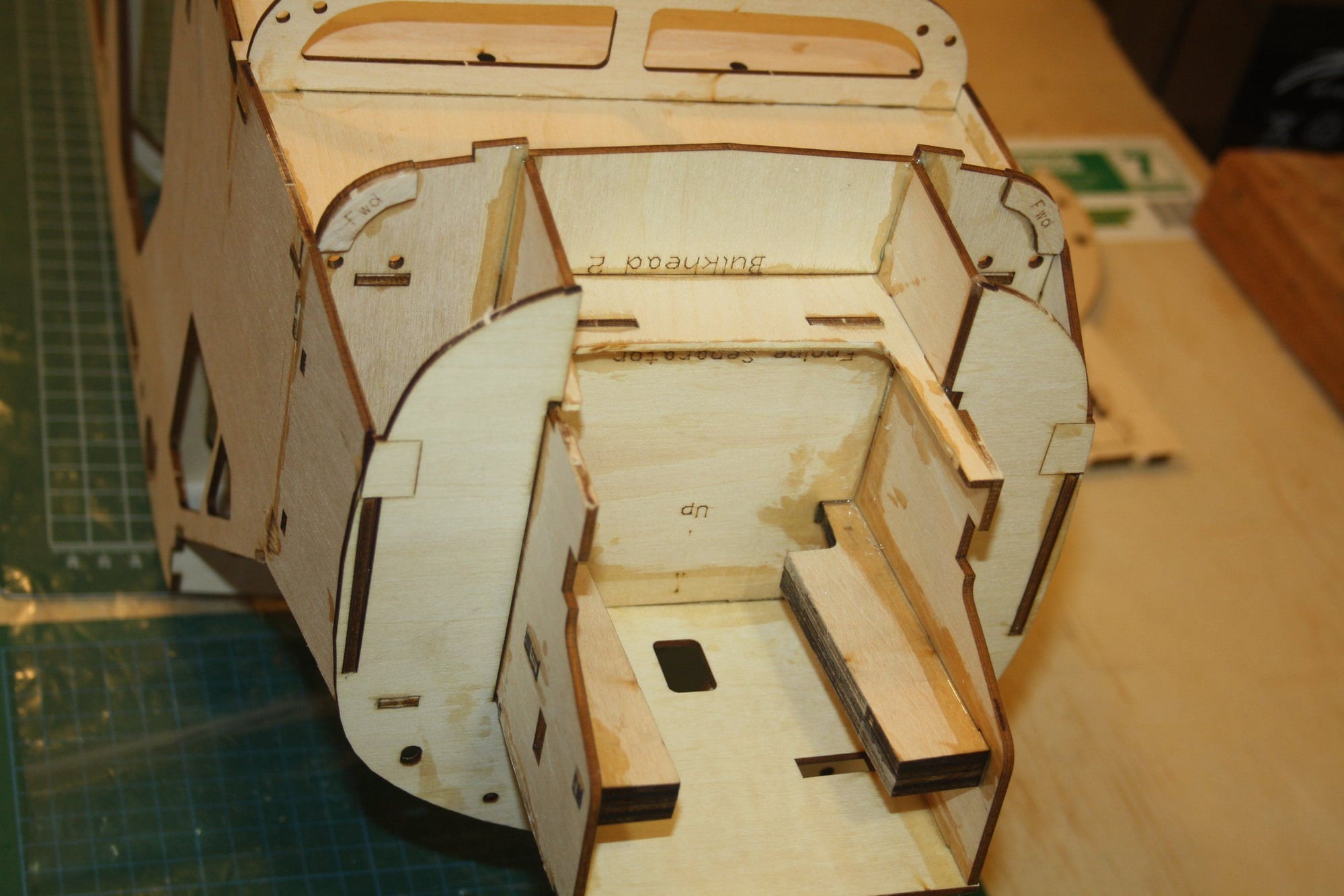
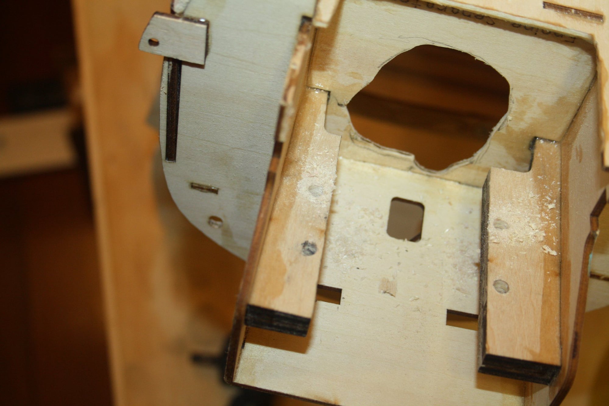
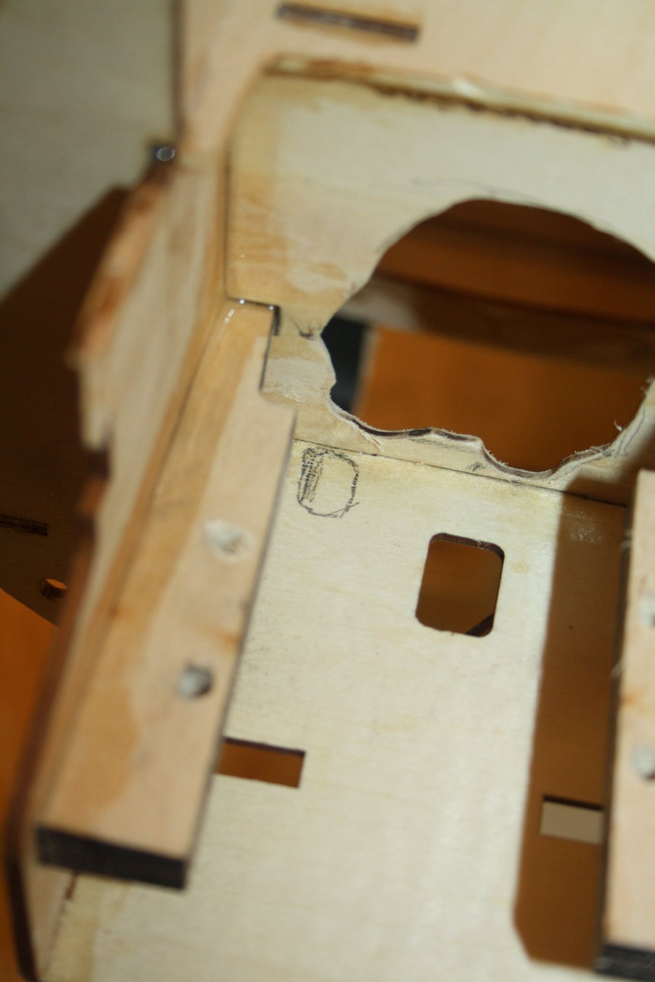
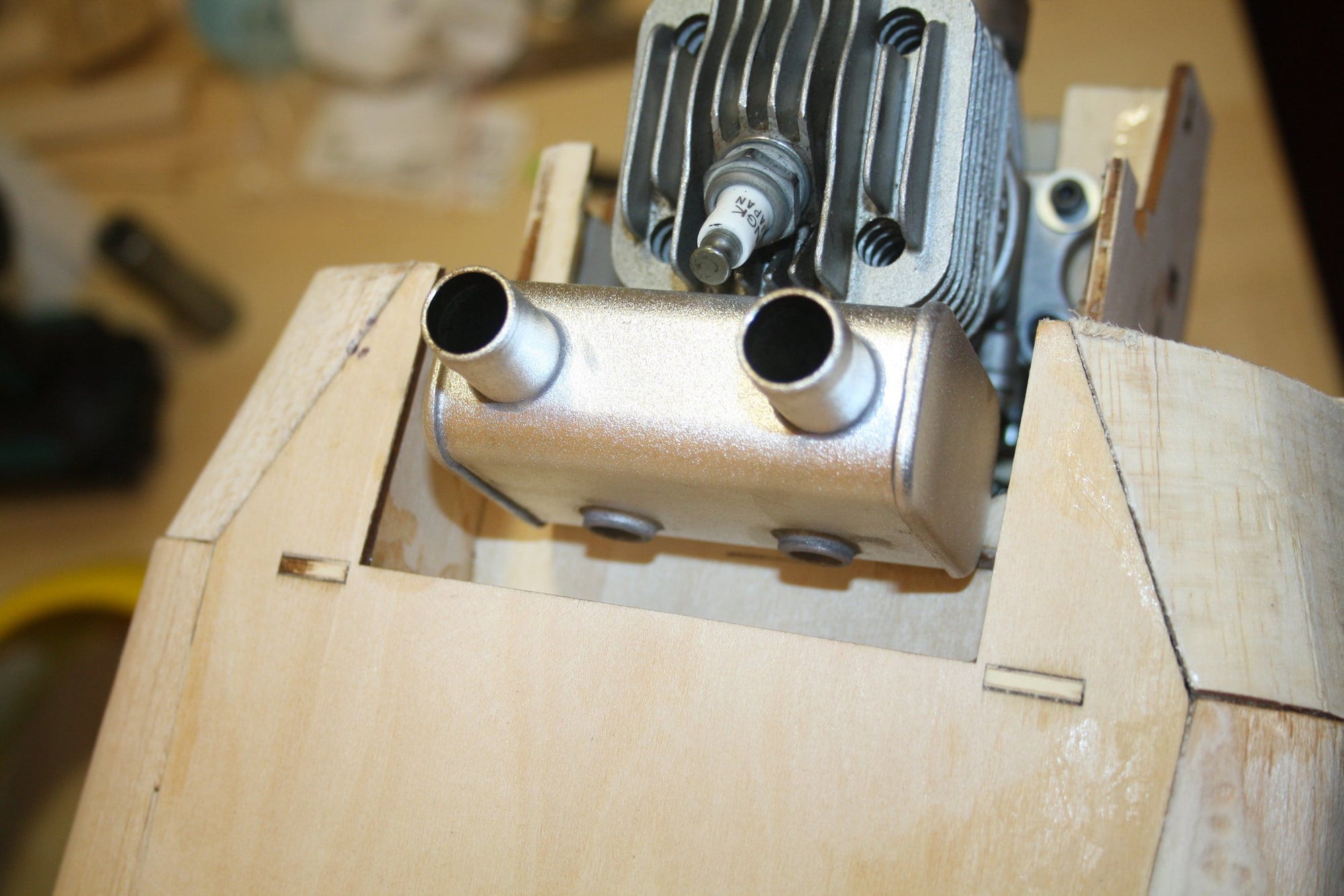
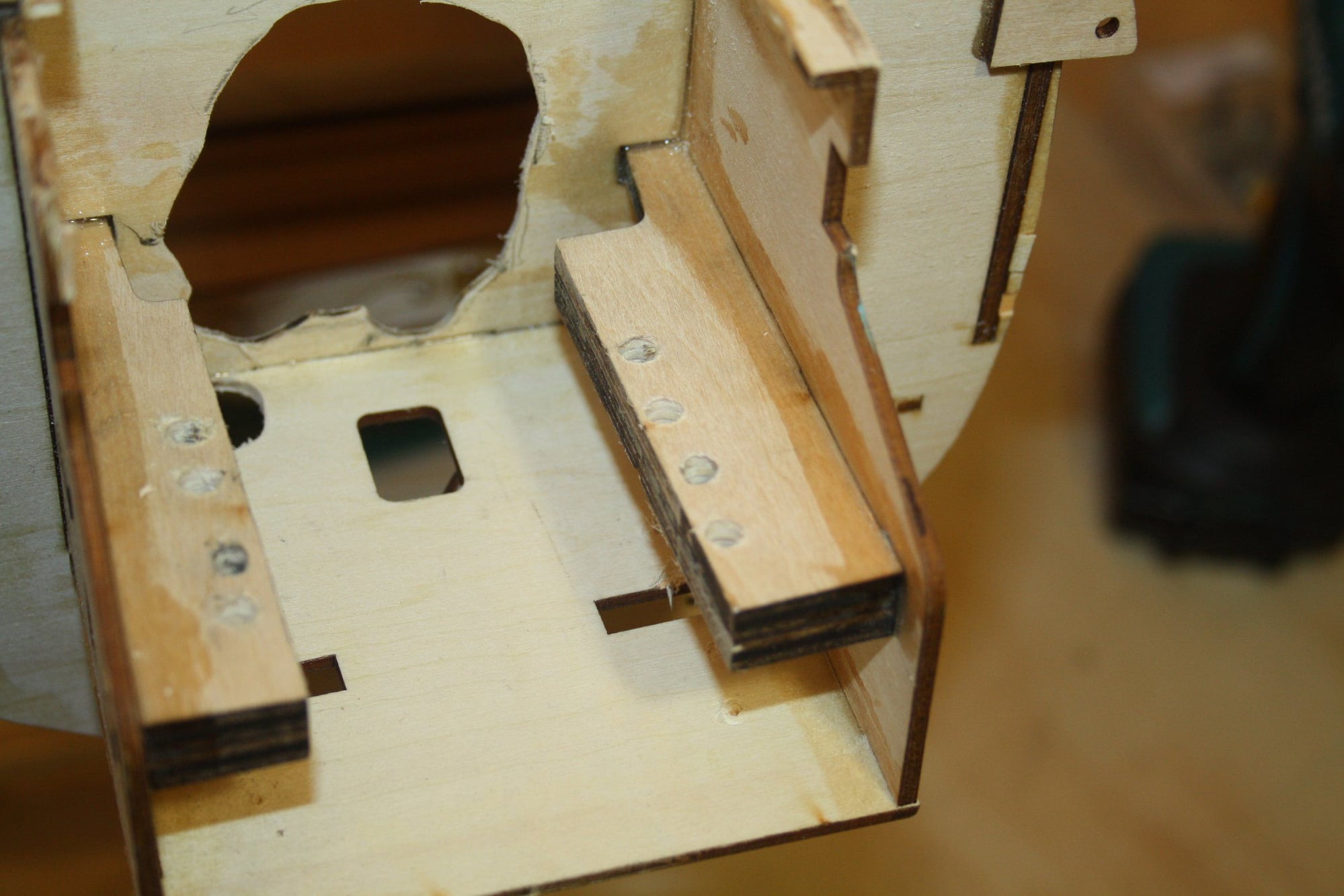
This kit was designed around the DLE-20 (or so it is stated). There are parts in the kit with markings for the different DLE engine assemblies. I had a DLE 20 RA waiting for a project, so it was the obvious choice. As can be seen in the photos, the markings are useless and to allow the rear muffler to exit a large cut out was required. If I remember correctly, the second photo show the "design" cut out...
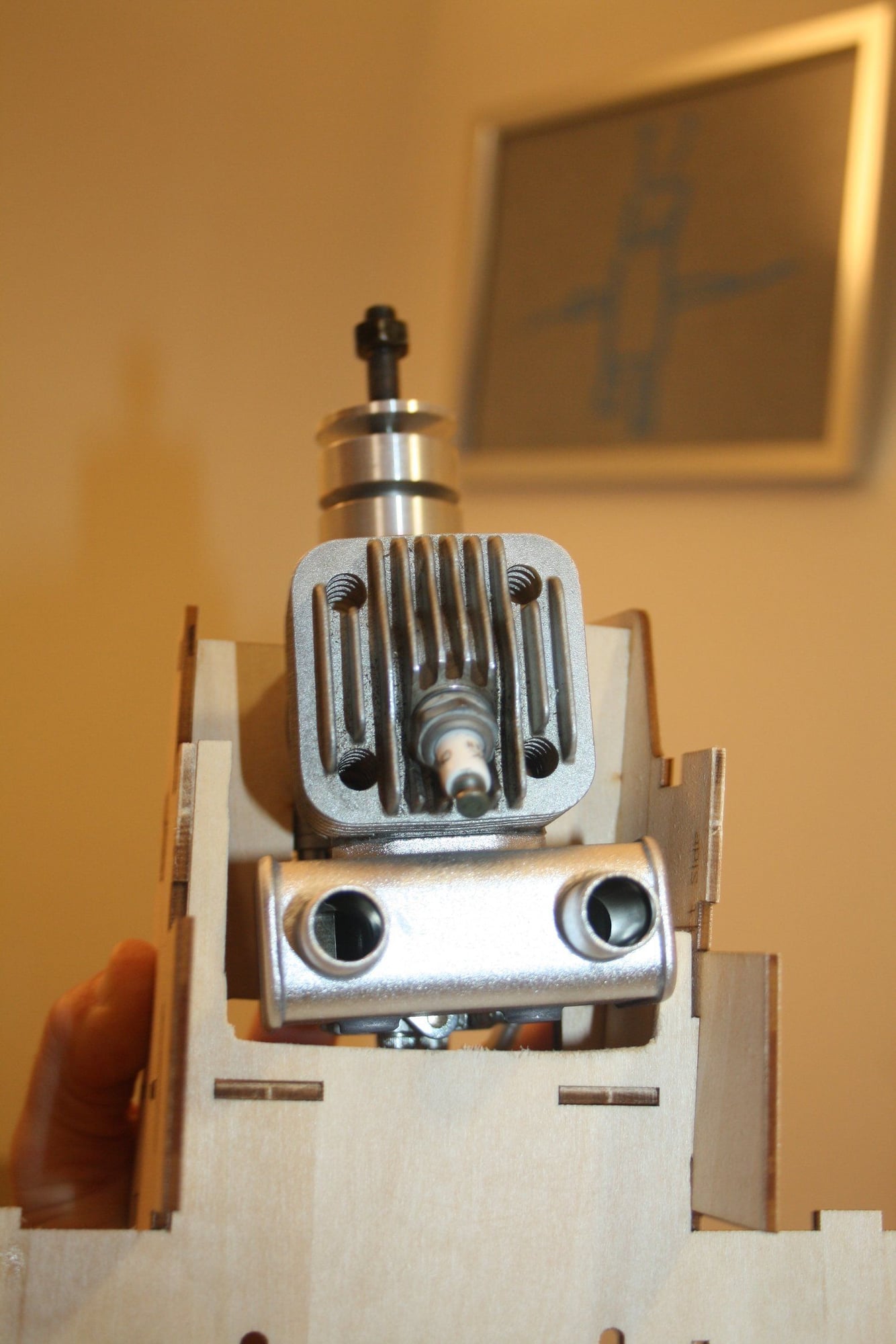
In addition, the provided mounts are not wide enough and are marginal for the drilling the mounting holes. I did not used the pre-drilled mounts as I was planning on mounting the engine further back to prevent the prop from being protruding very far away from the cowl. As a general note, the whole design of the area in front of the firewall is poor design and the access to the mounting beams is poor. It would have been far better to leave a flat firewall and leave the engine mounting alone to the user fitting beam mounts.
Cheers,
Eran
This kit was designed around the DLE-20 (or so it is stated). There are parts in the kit with markings for the different DLE engine assemblies. I had a DLE 20 RA waiting for a project, so it was the obvious choice. As can be seen in the photos, the markings are useless and to allow the rear muffler to exit a large cut out was required. If I remember correctly, the second photo show the "design" cut out...
In addition, the provided mounts are not wide enough and are marginal for the drilling the mounting holes. I did not used the pre-drilled mounts as I was planning on mounting the engine further back to prevent the prop from being protruding very far away from the cowl. As a general note, the whole design of the area in front of the firewall is poor design and the access to the mounting beams is poor. It would have been far better to leave a flat firewall and leave the engine mounting alone to the user fitting beam mounts.
Cheers,
Eran
 10-21-2022, 09:55 PM
#56
Thread Starter
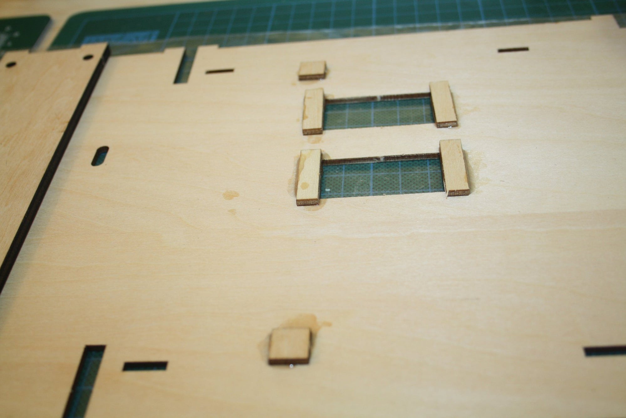
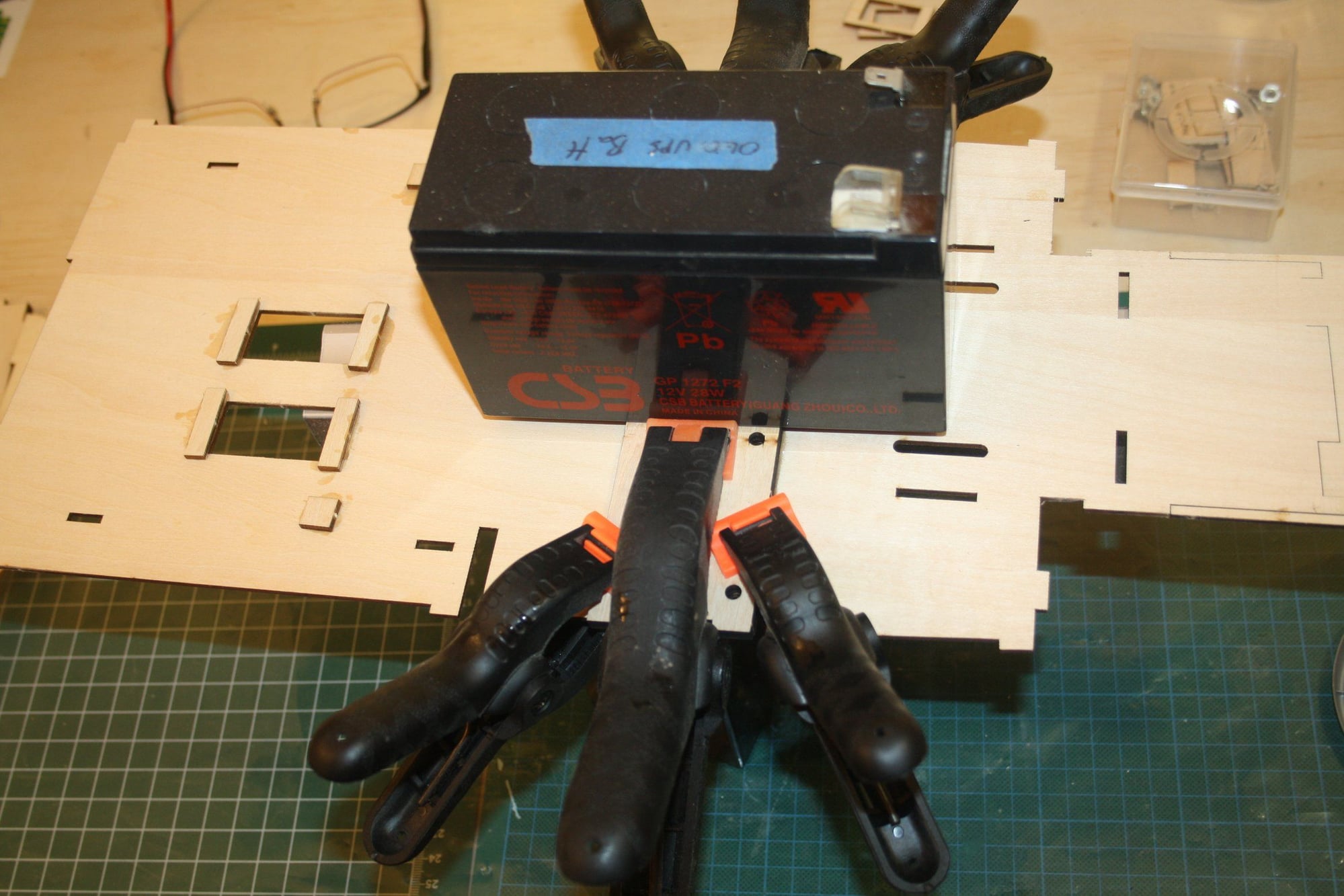
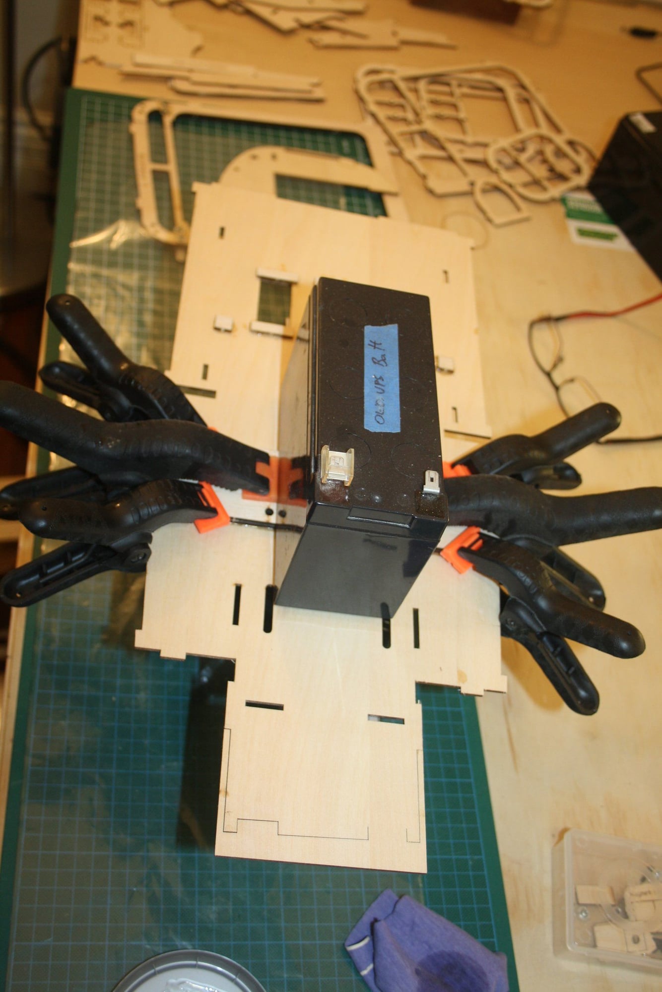
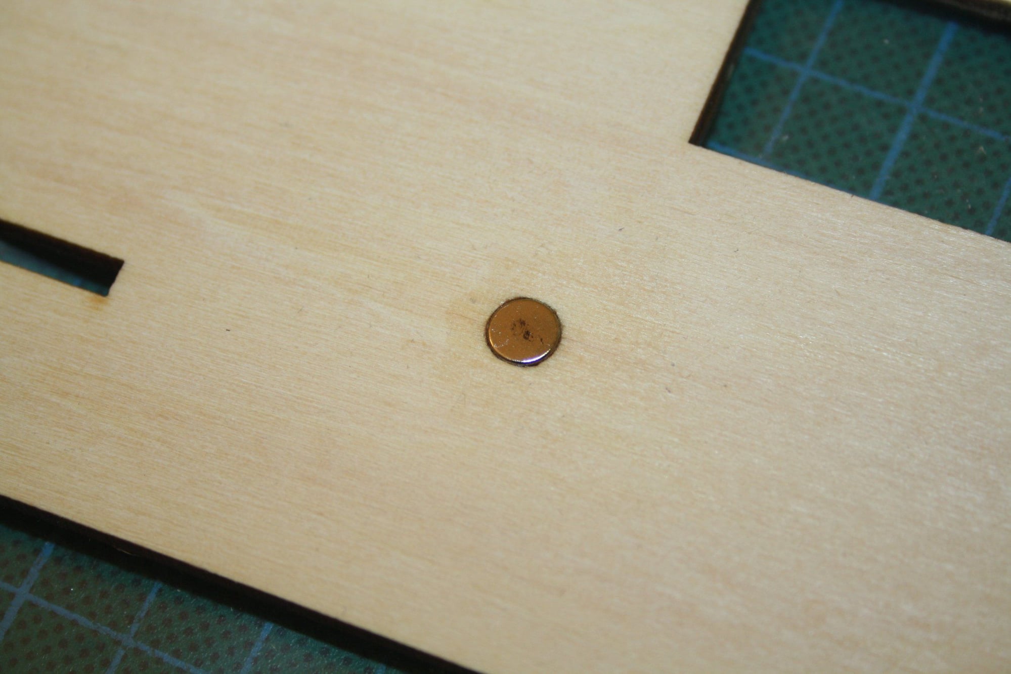
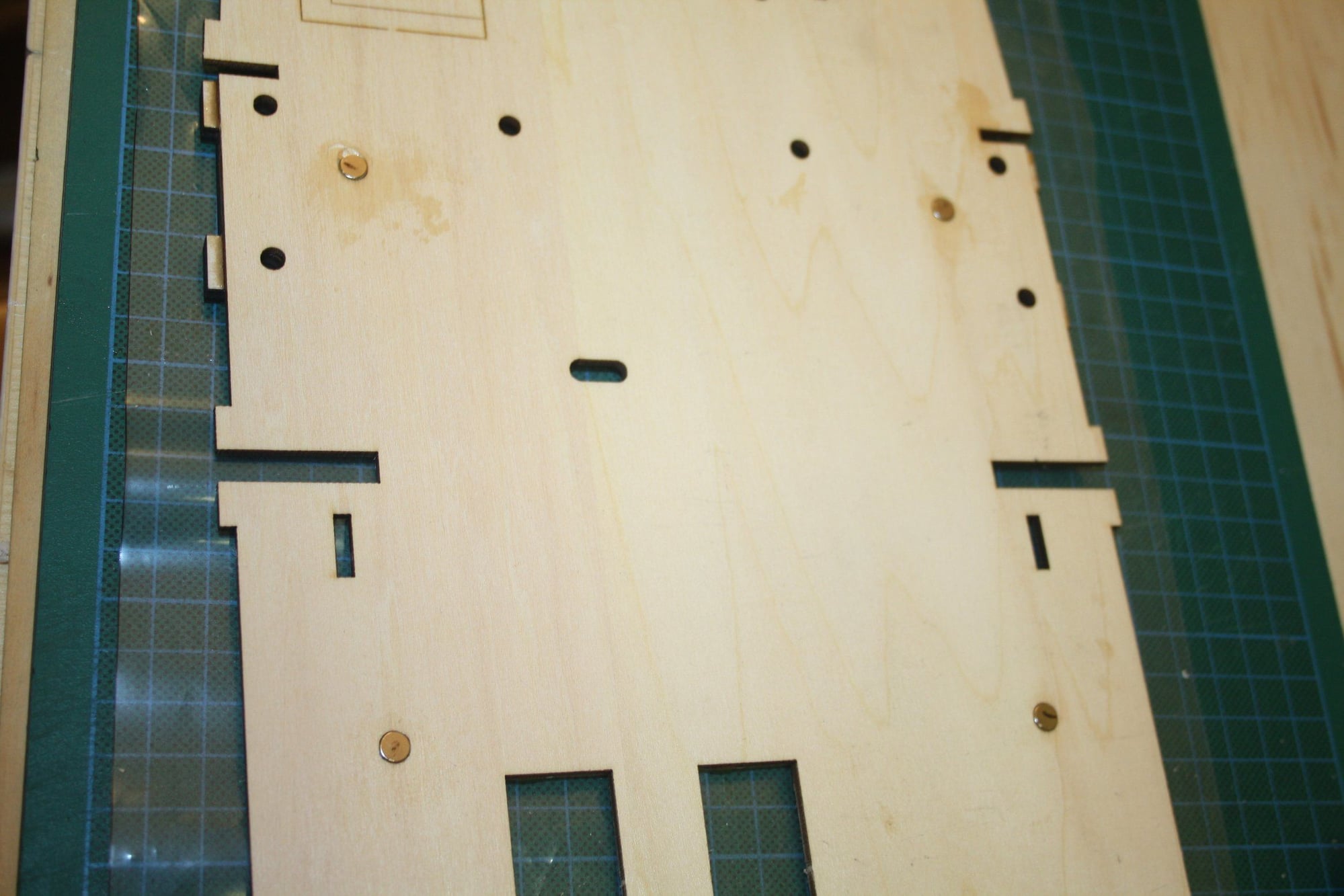
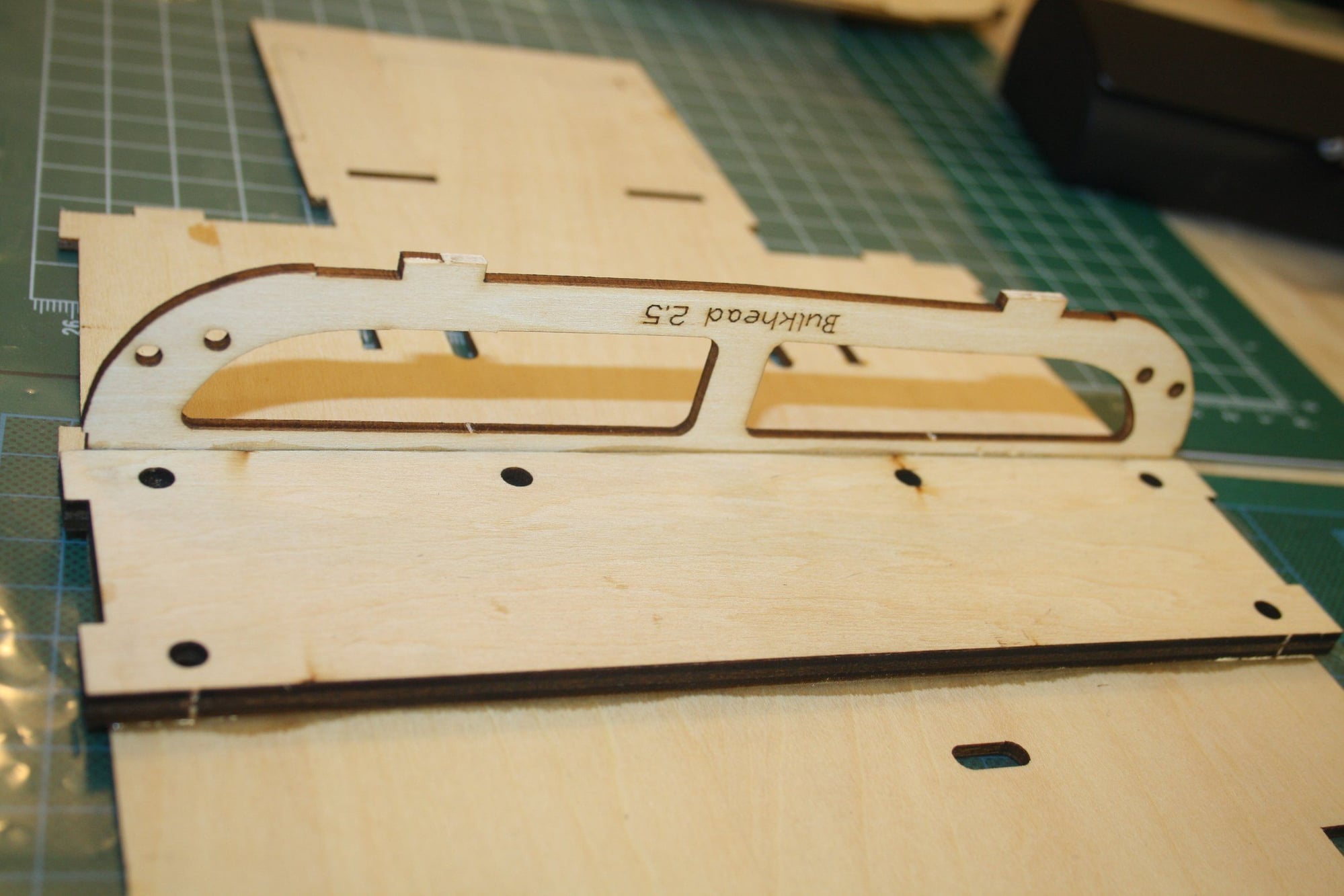
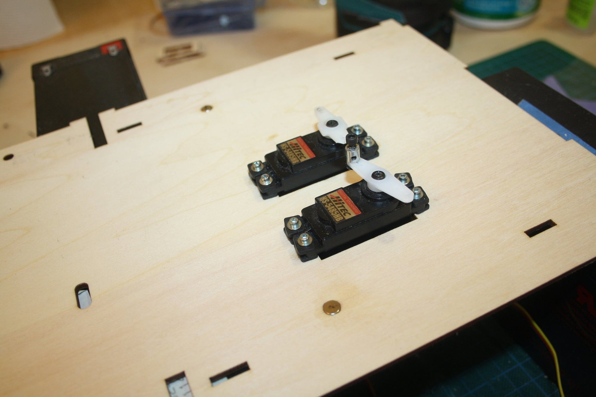
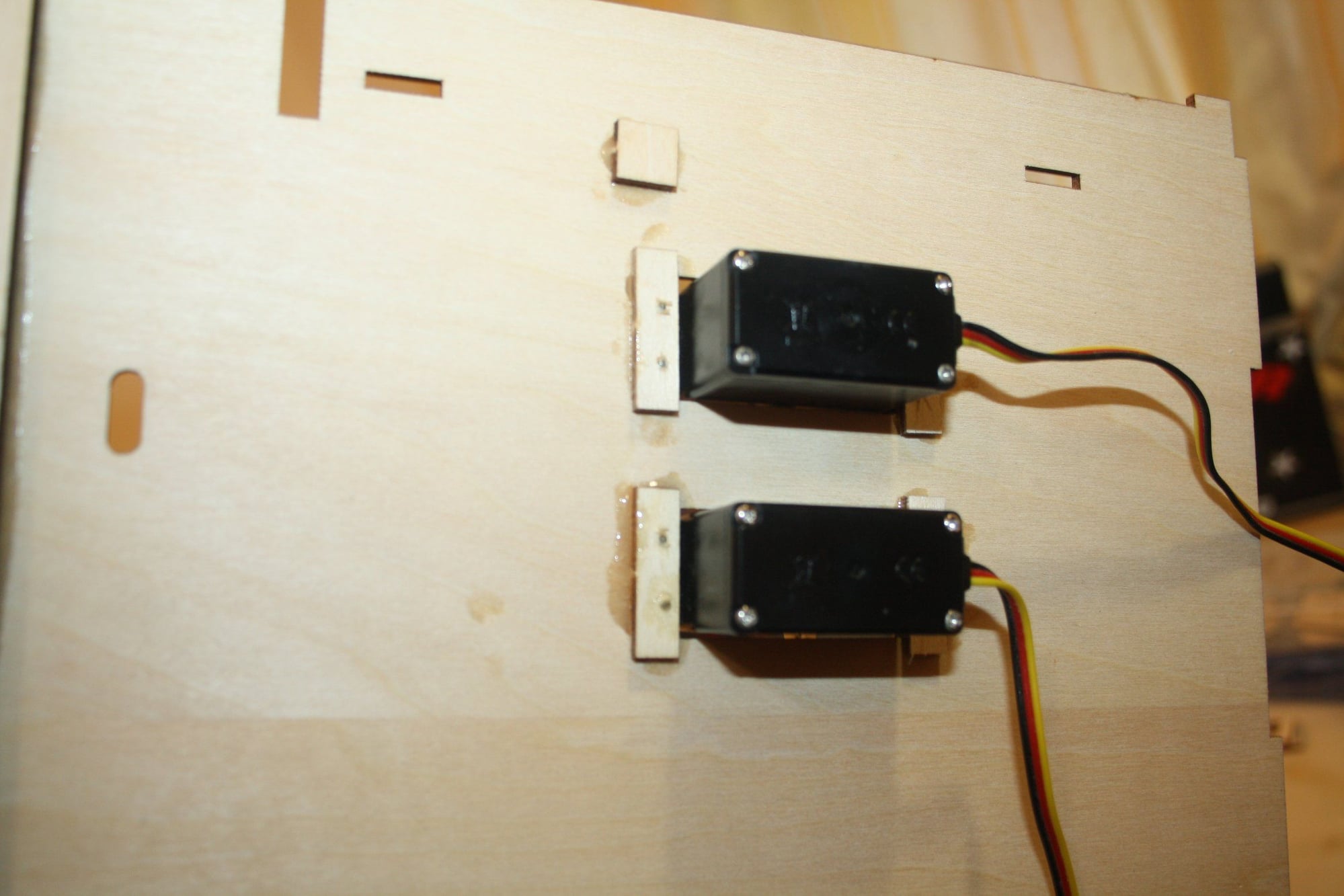
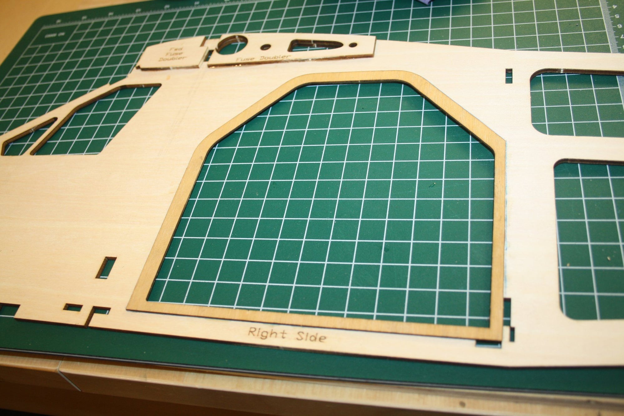
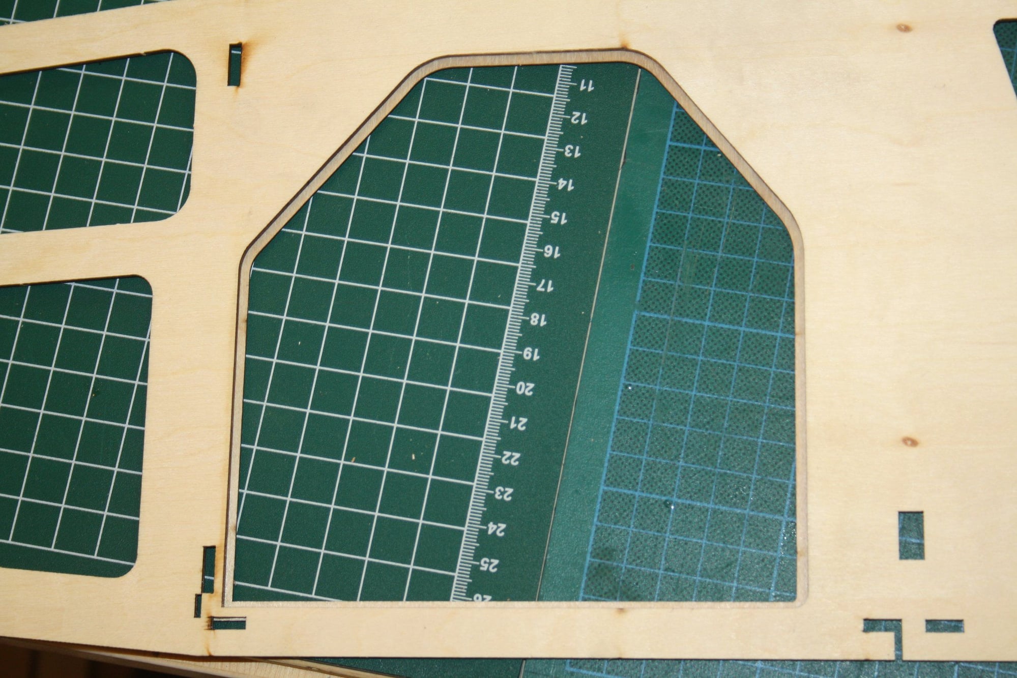
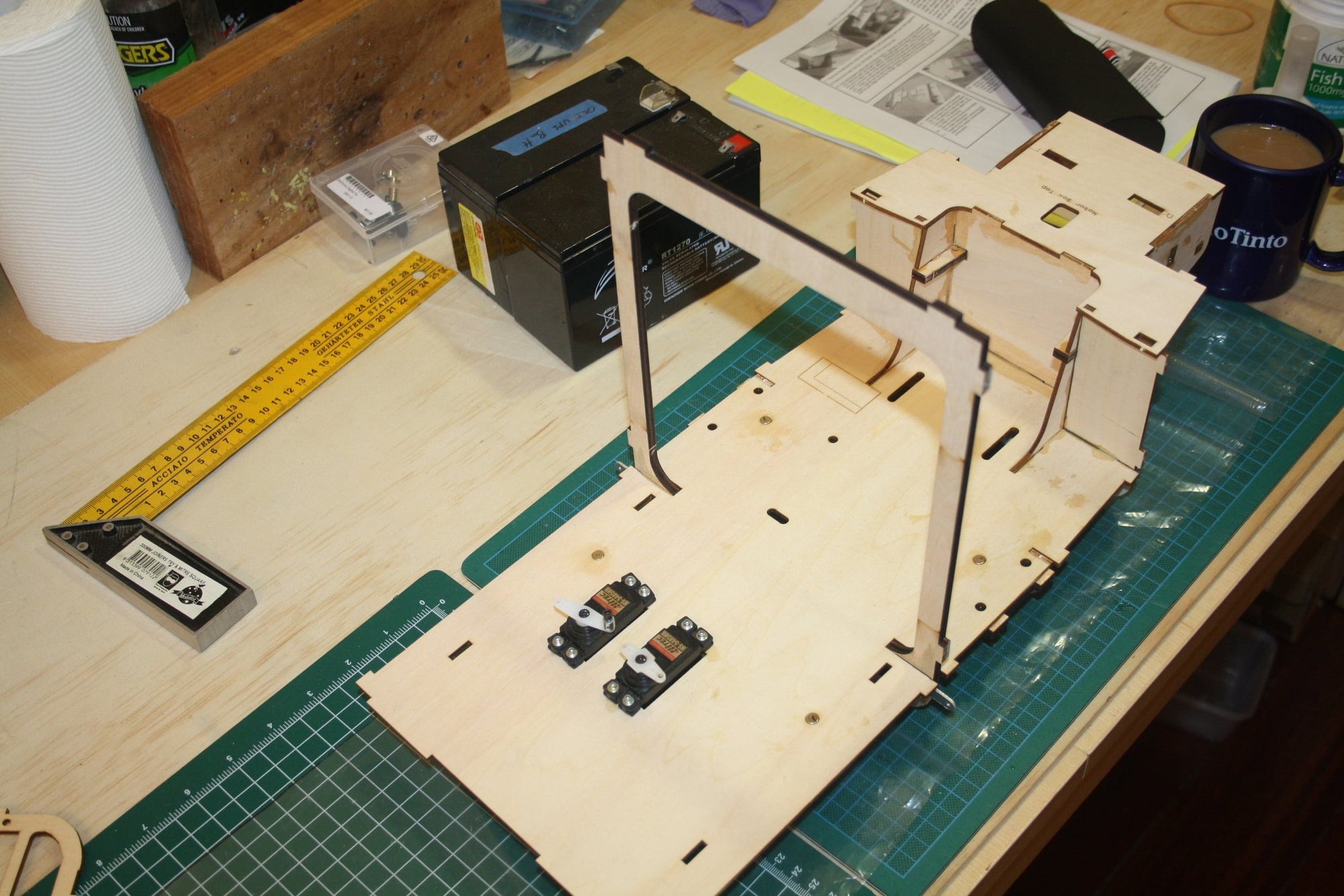
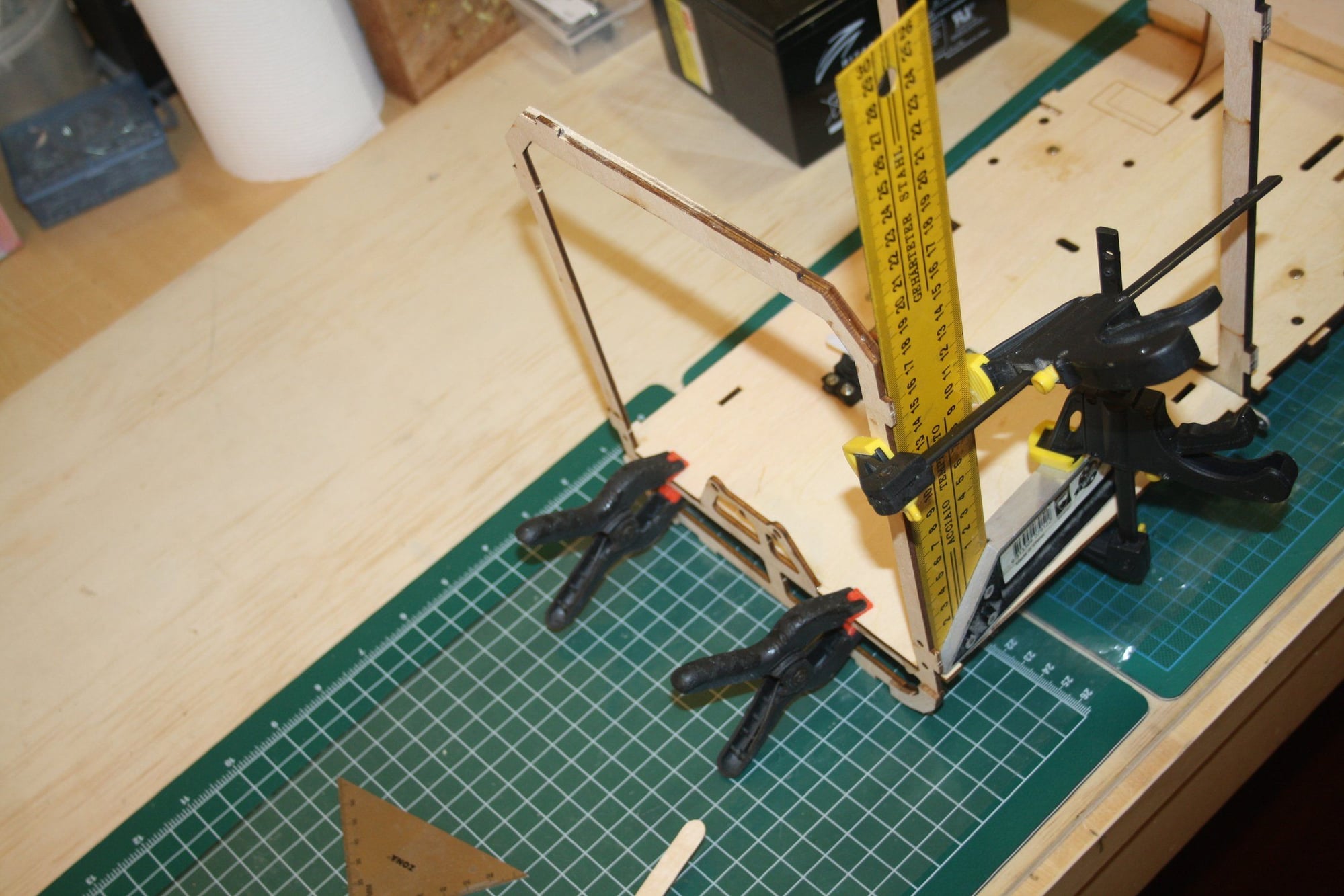
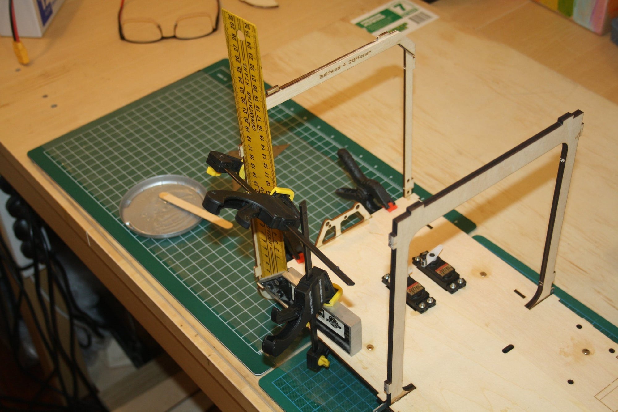
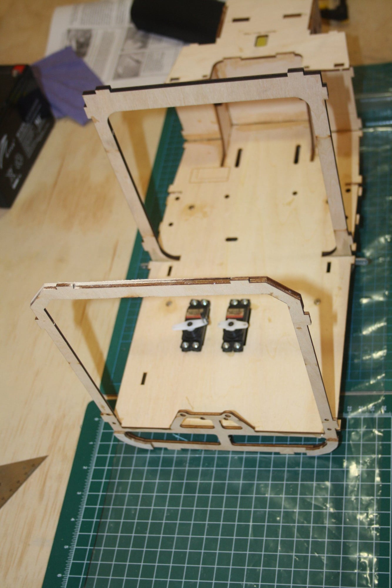
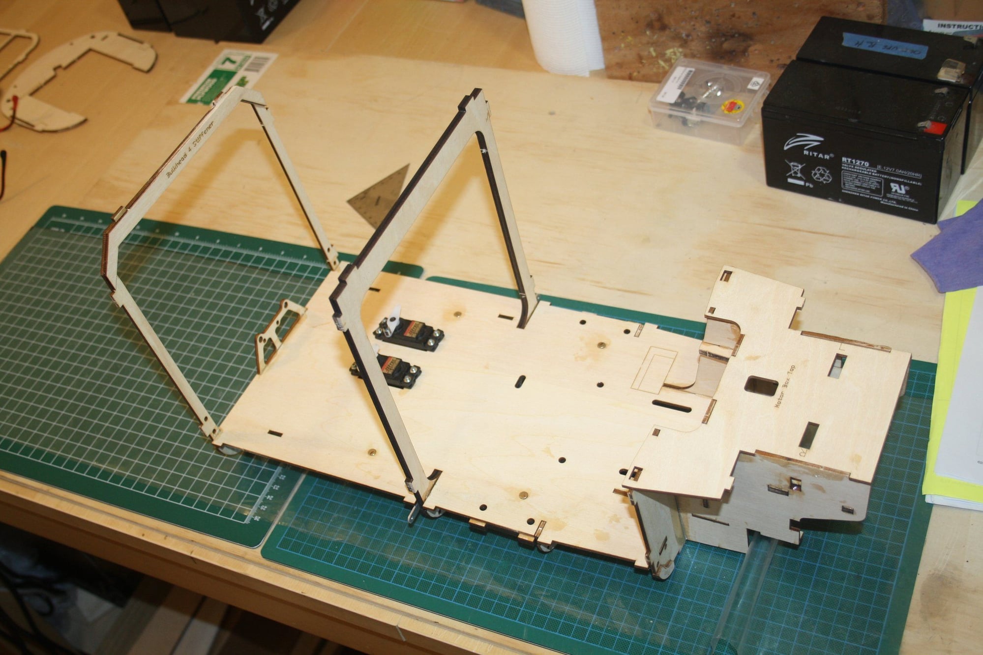
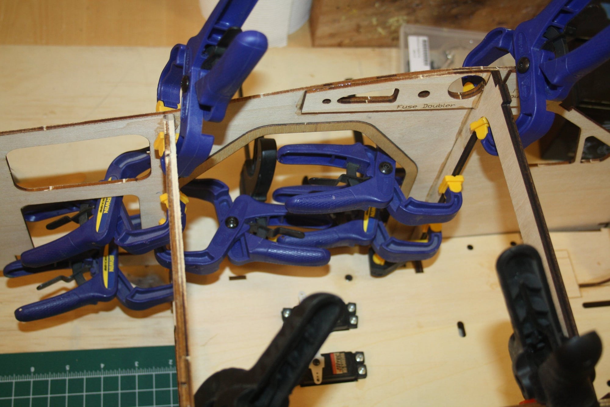
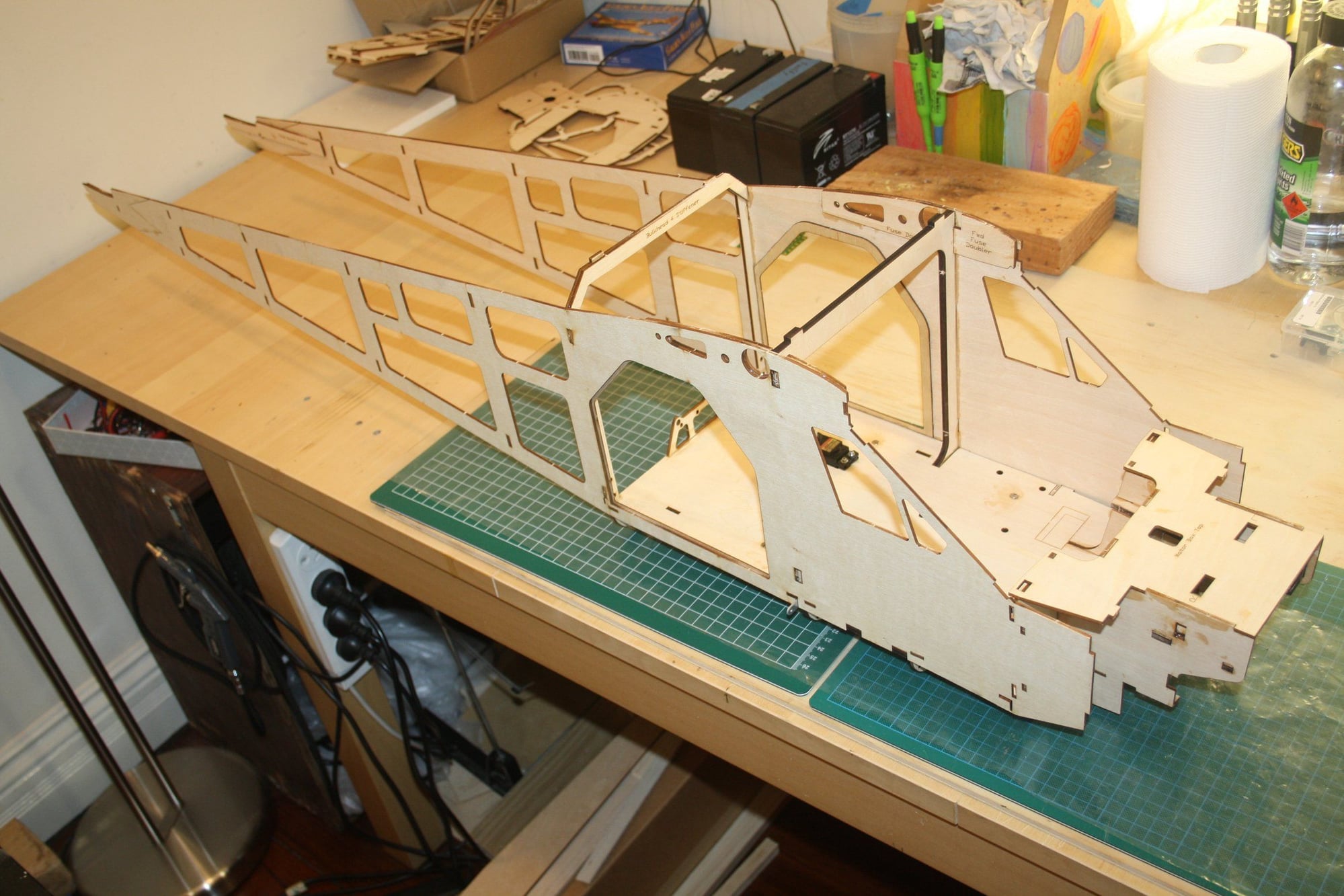
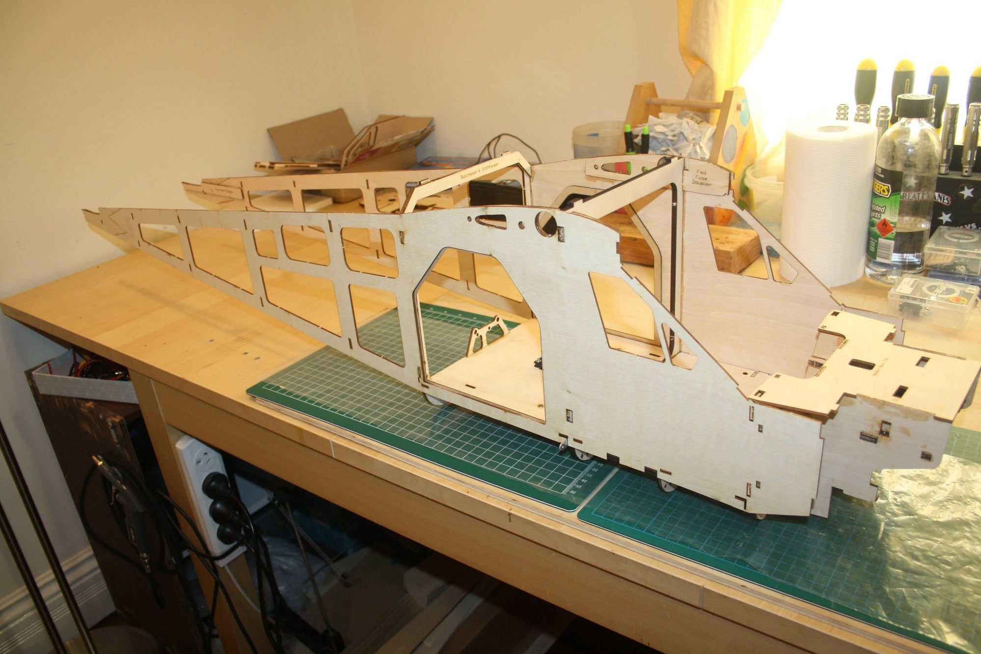
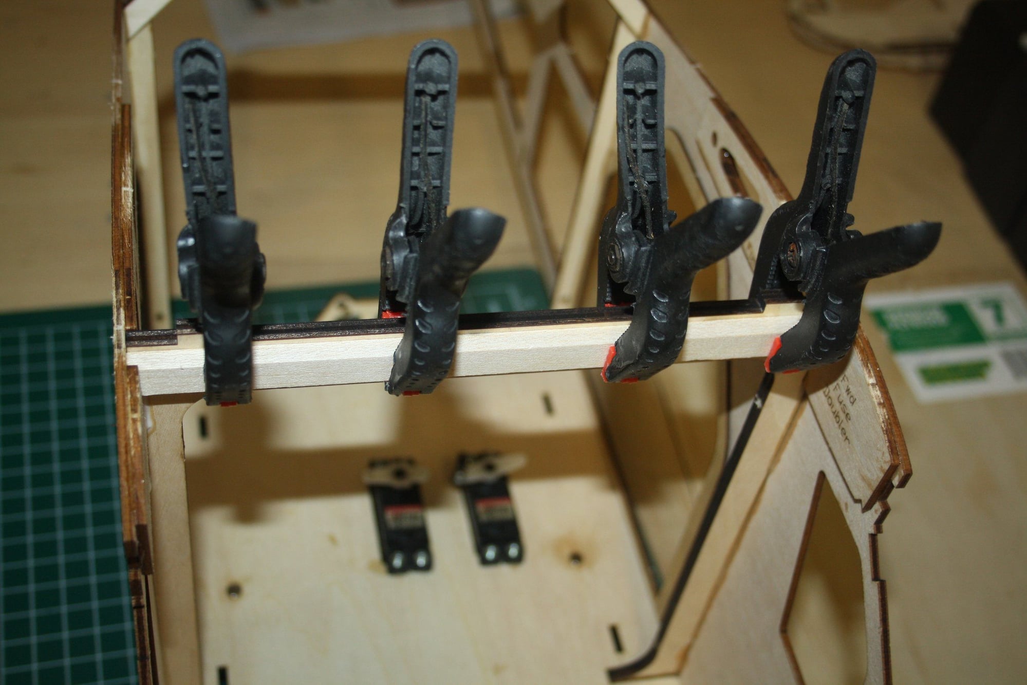
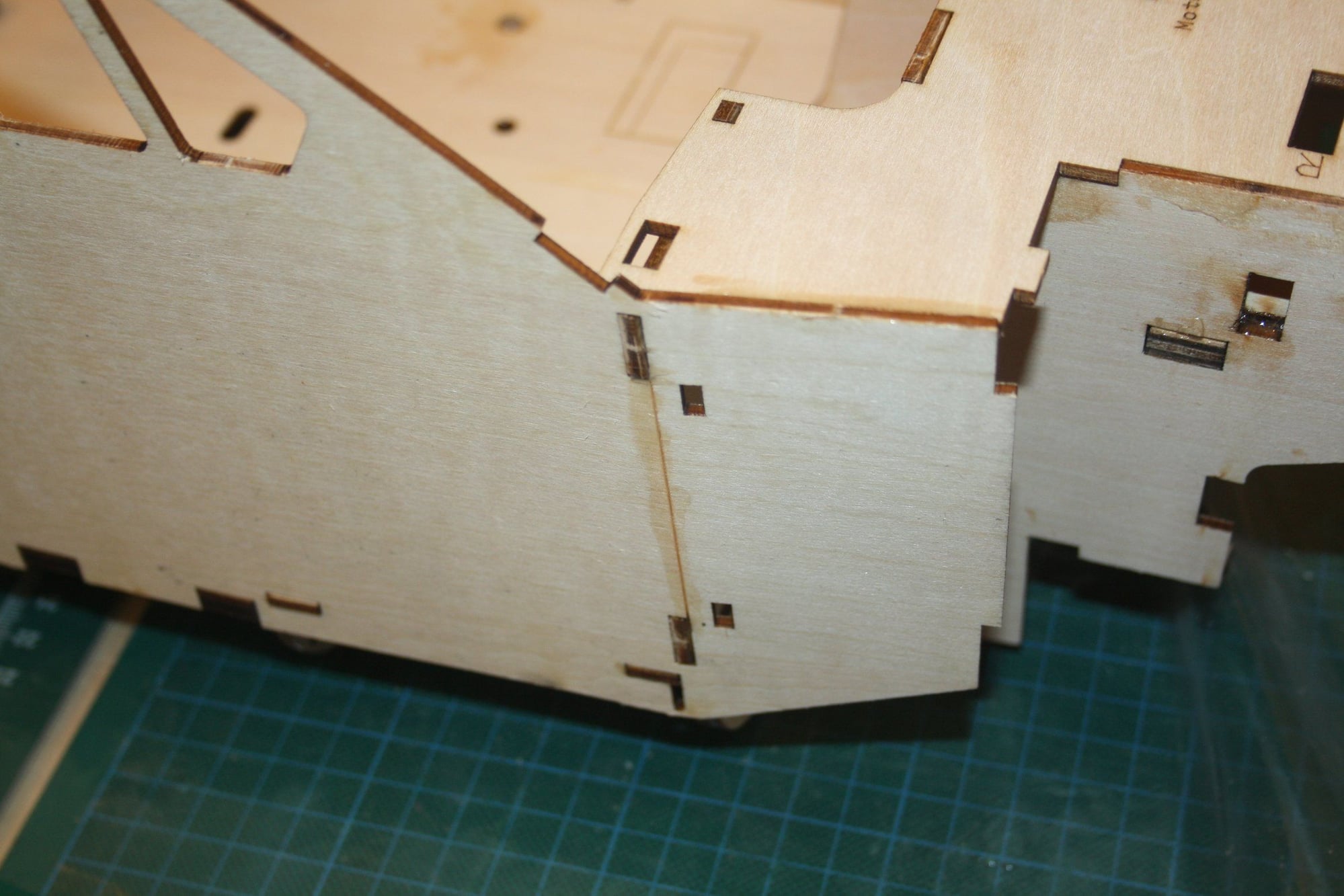
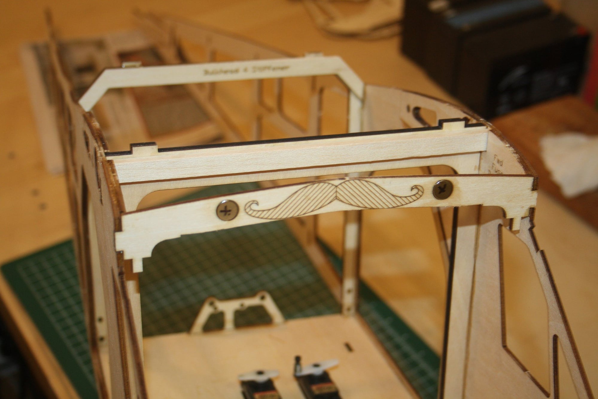
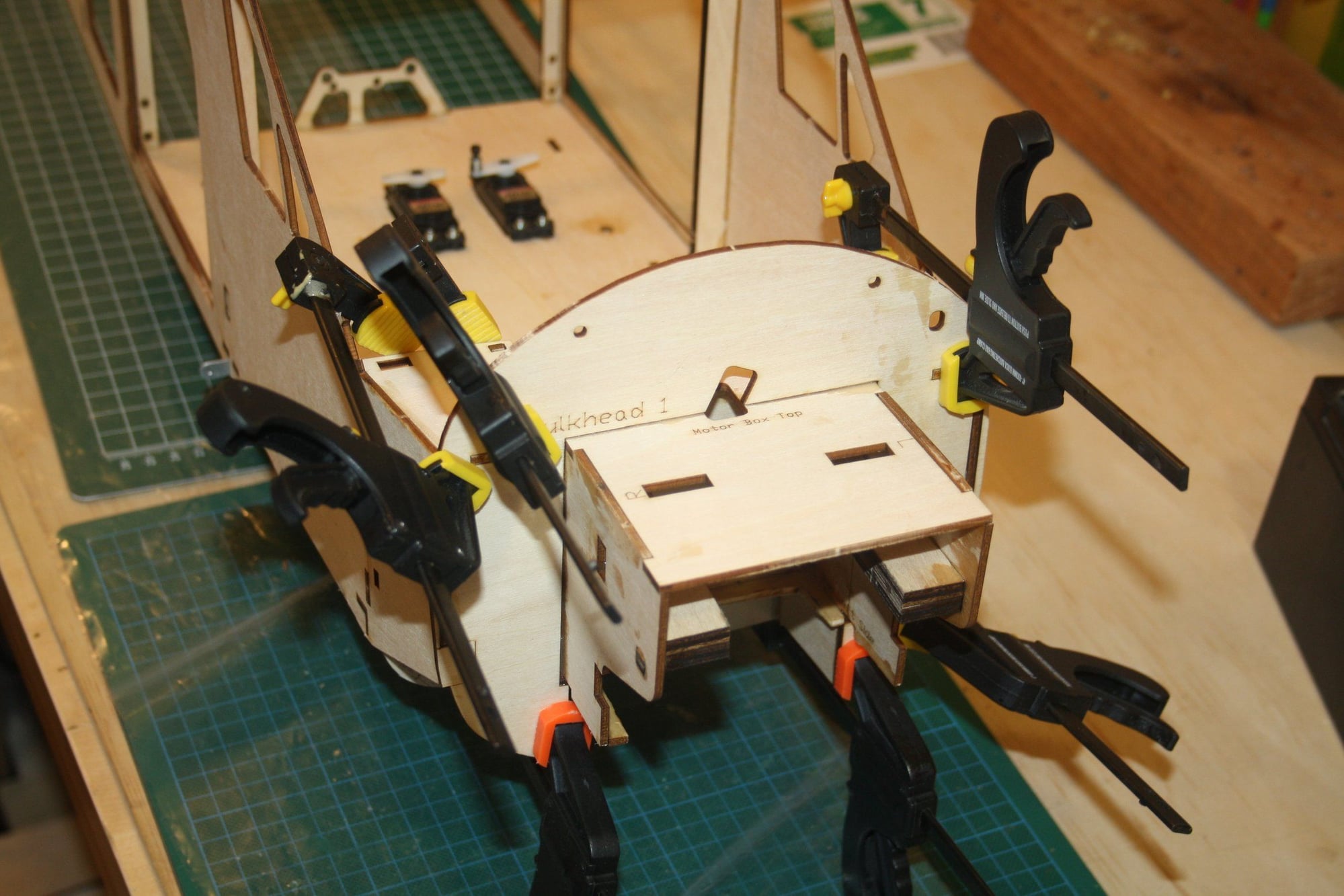
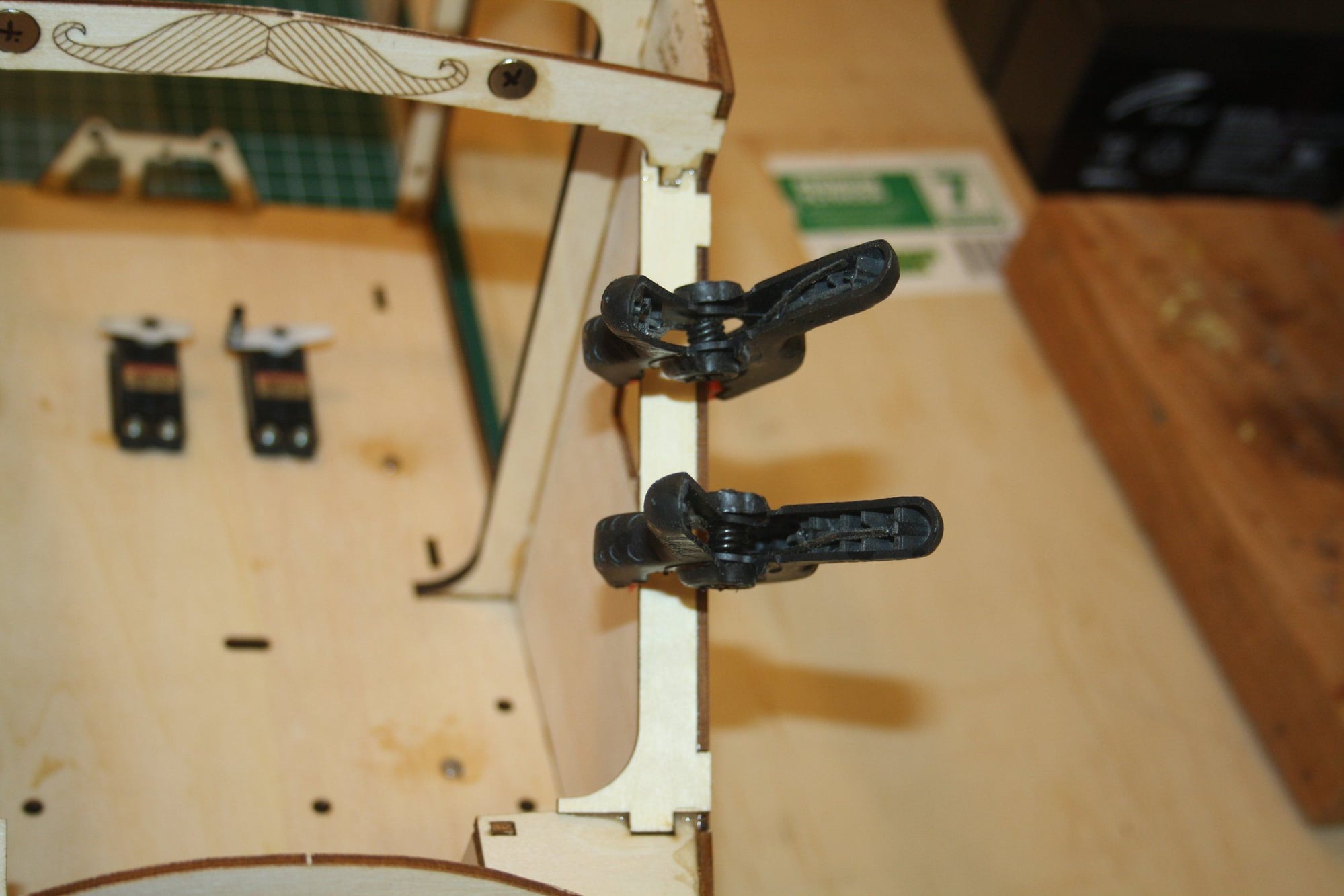
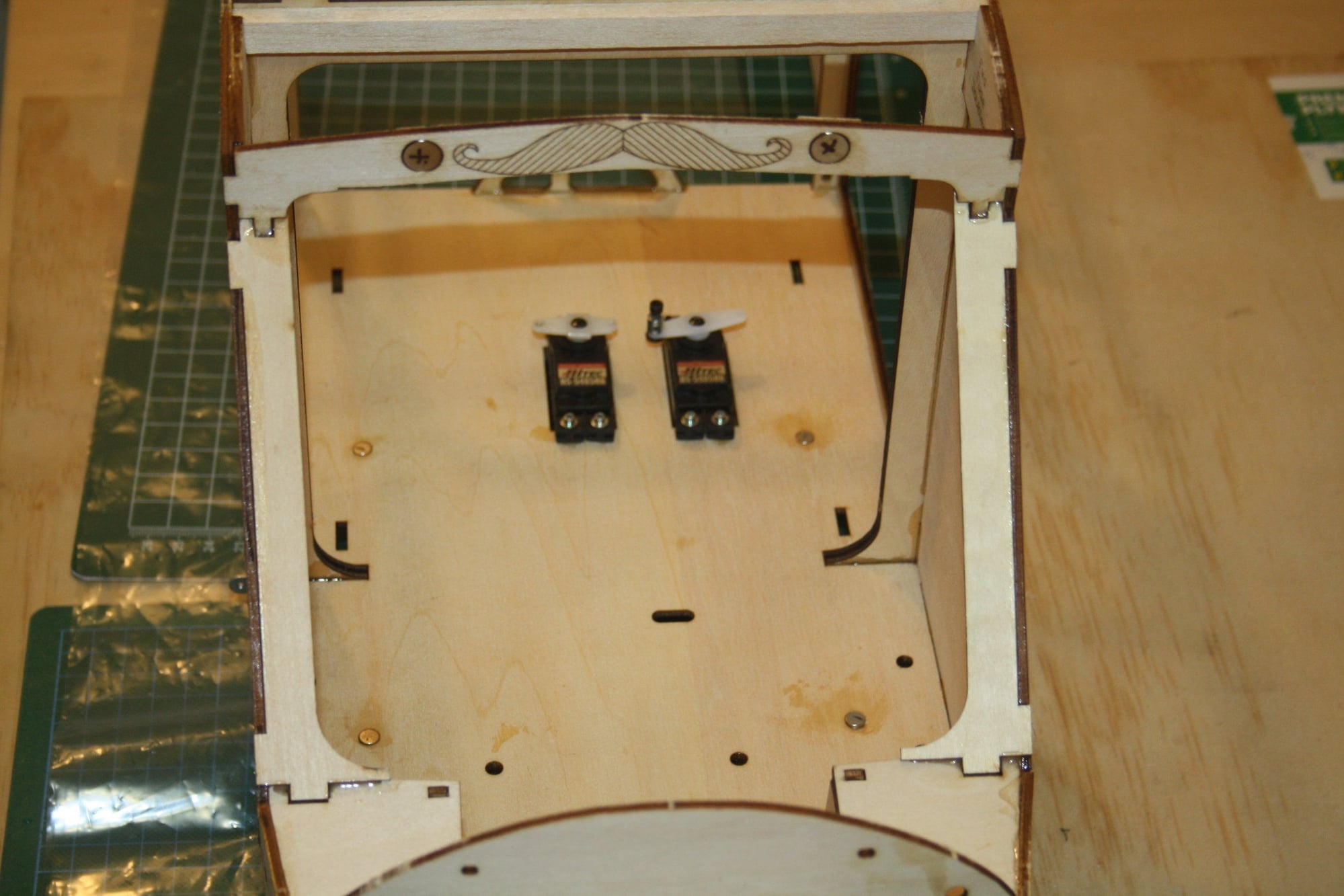
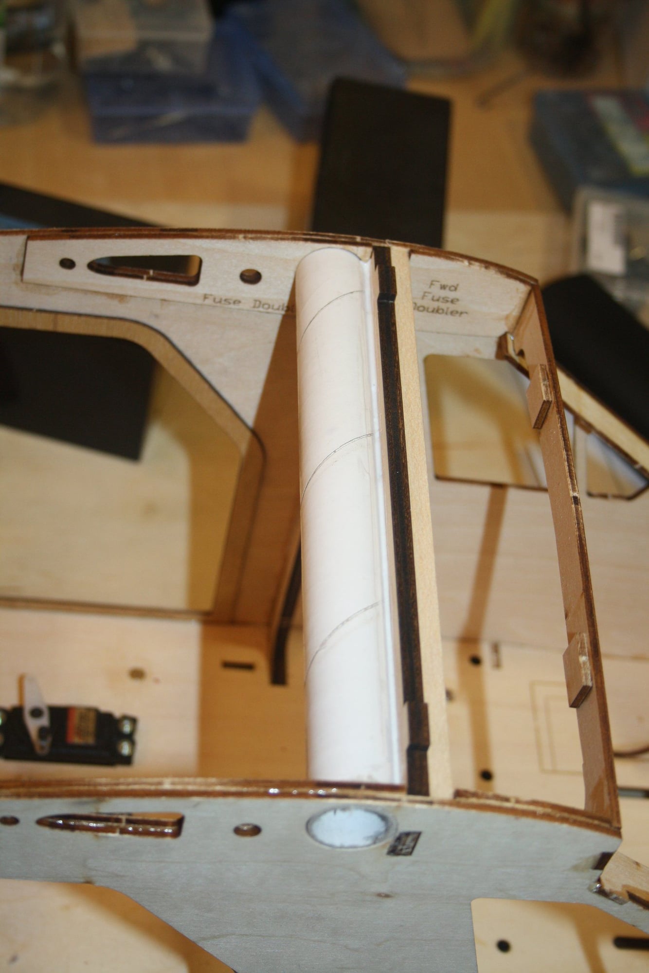
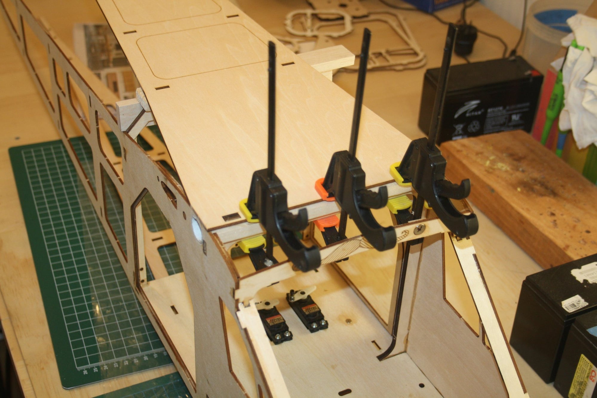
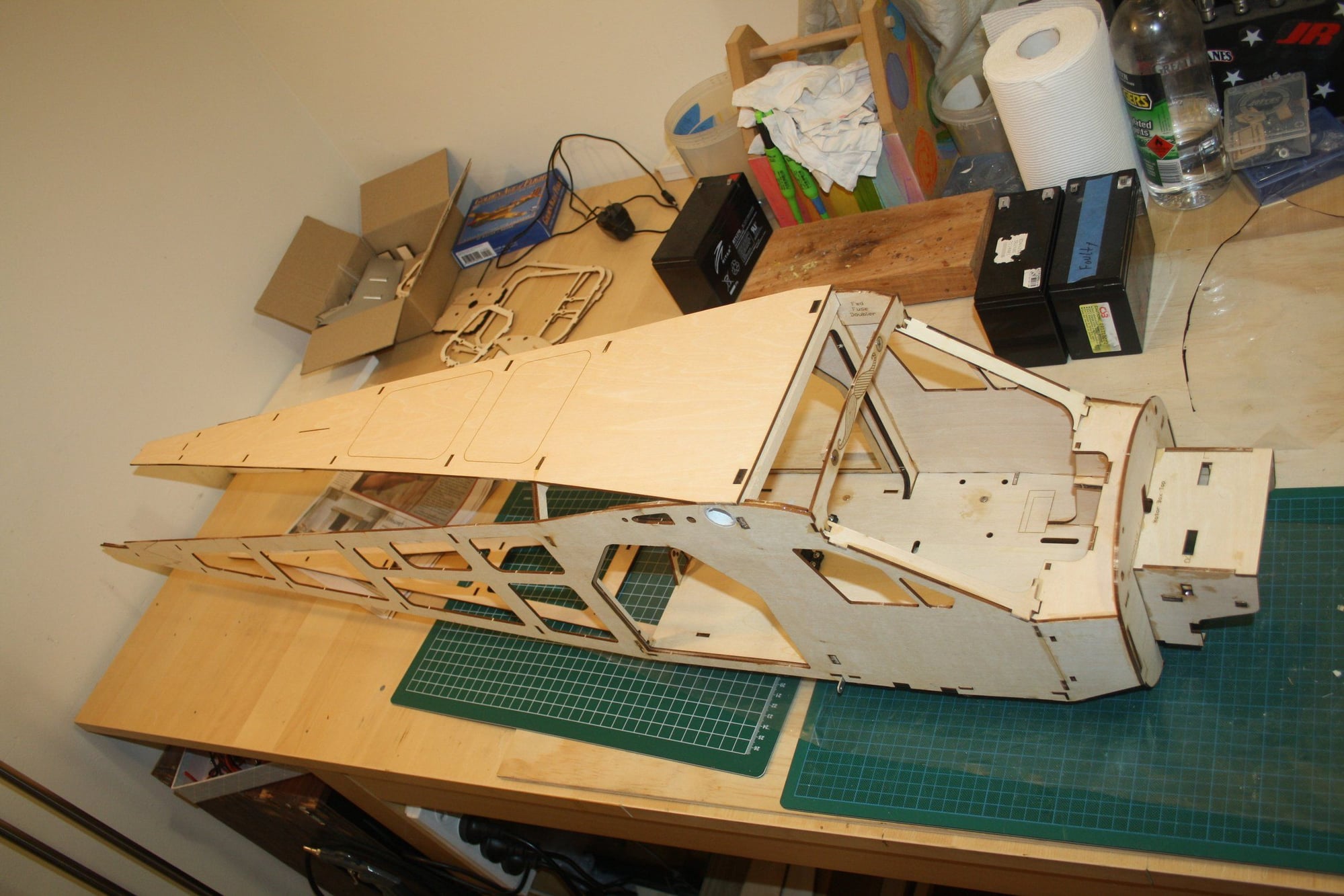
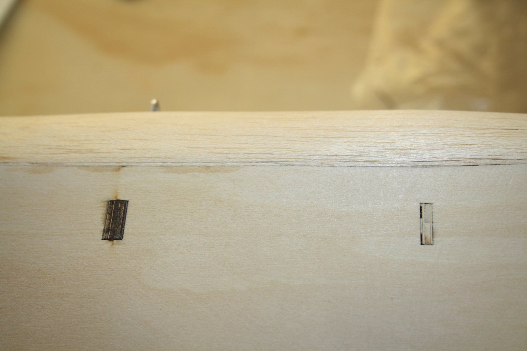
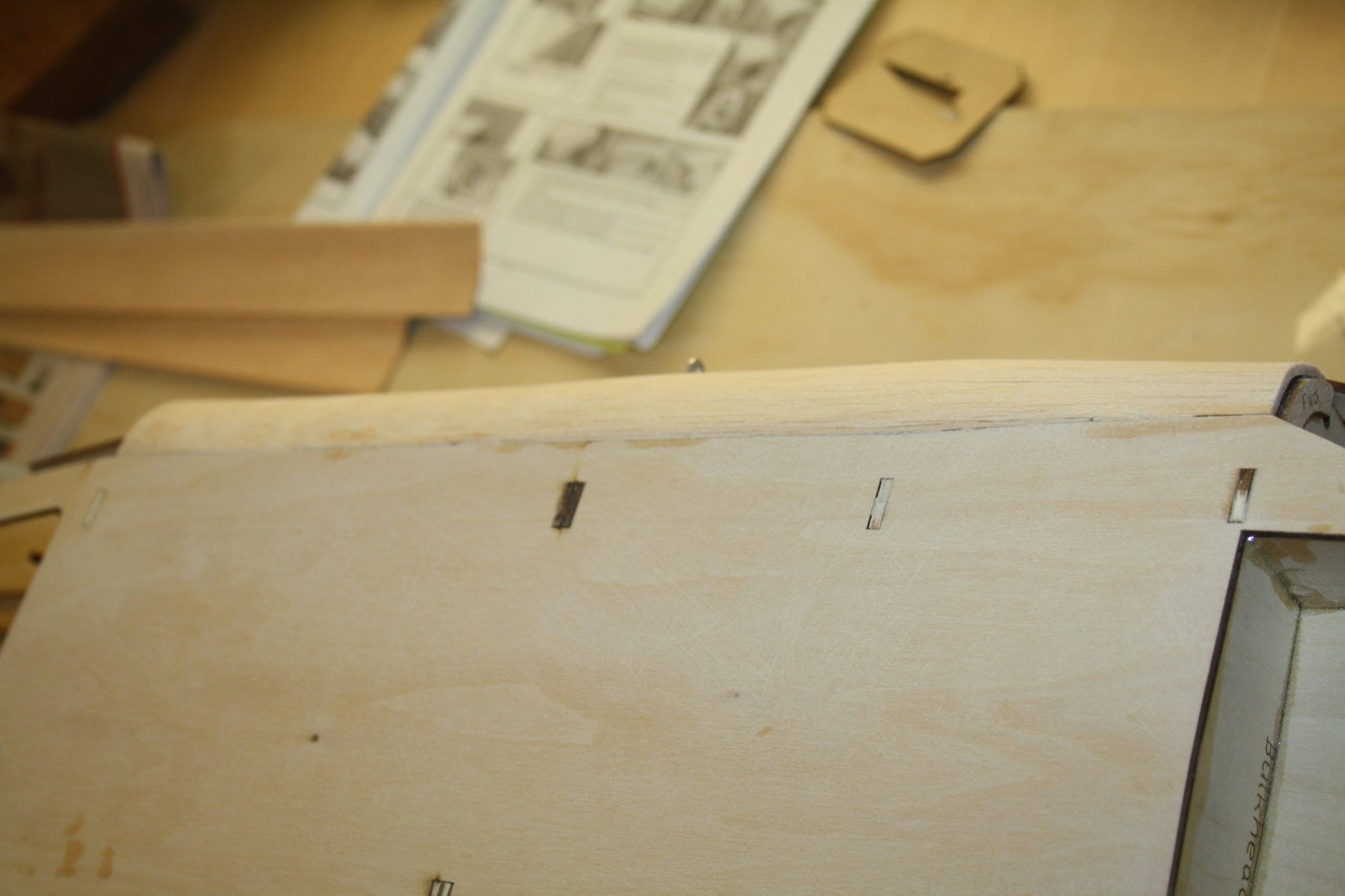
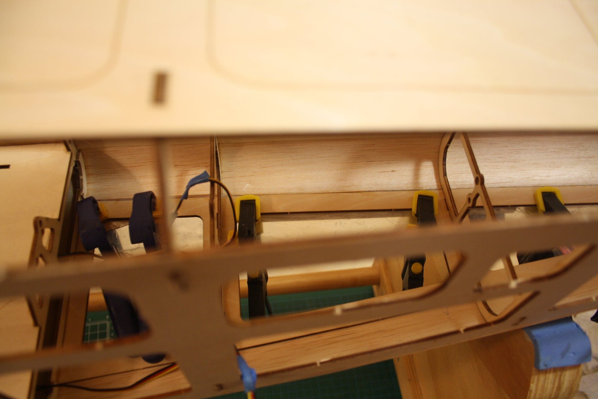
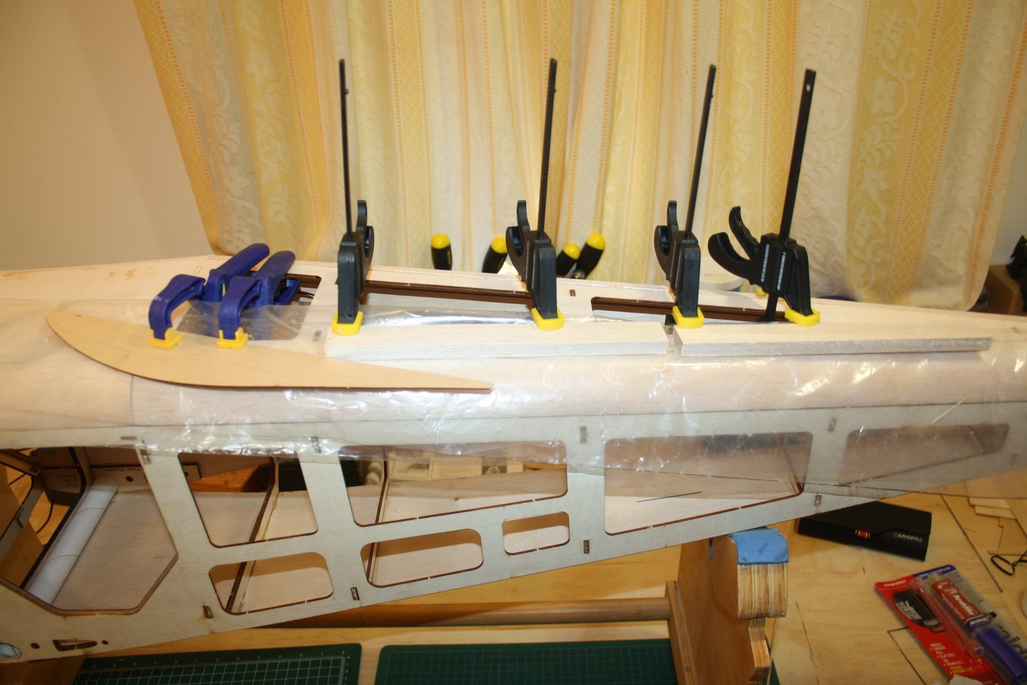
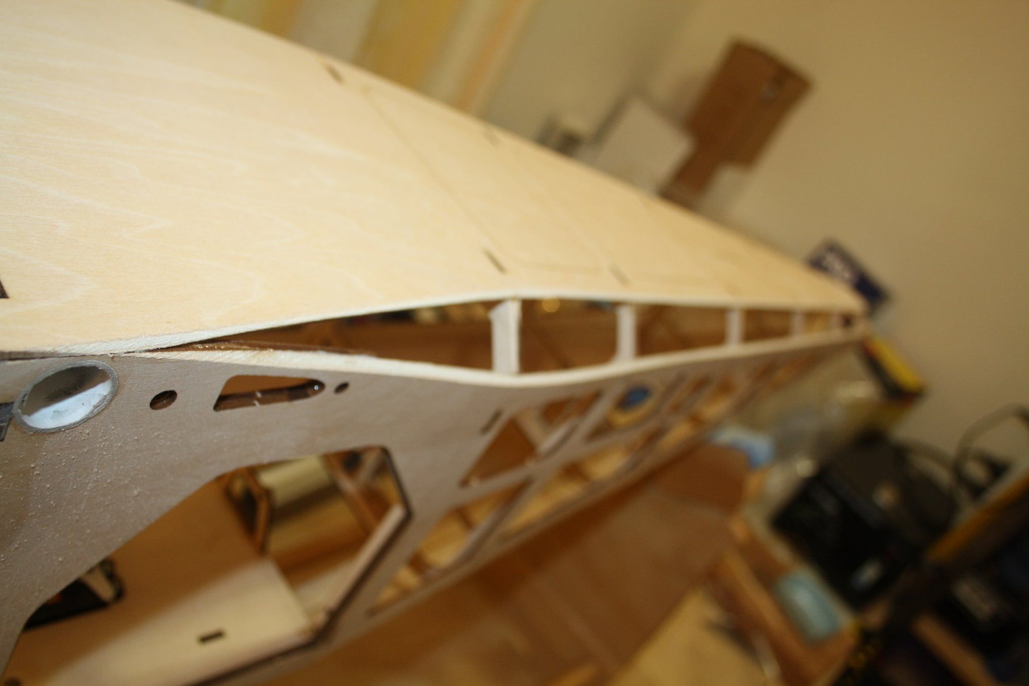
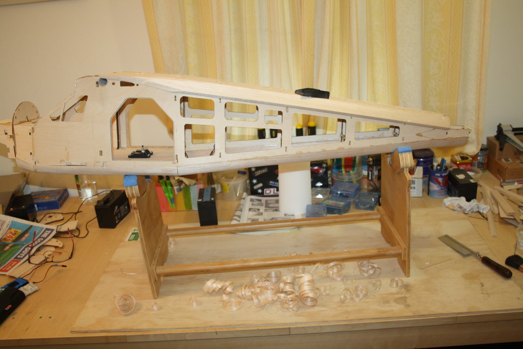
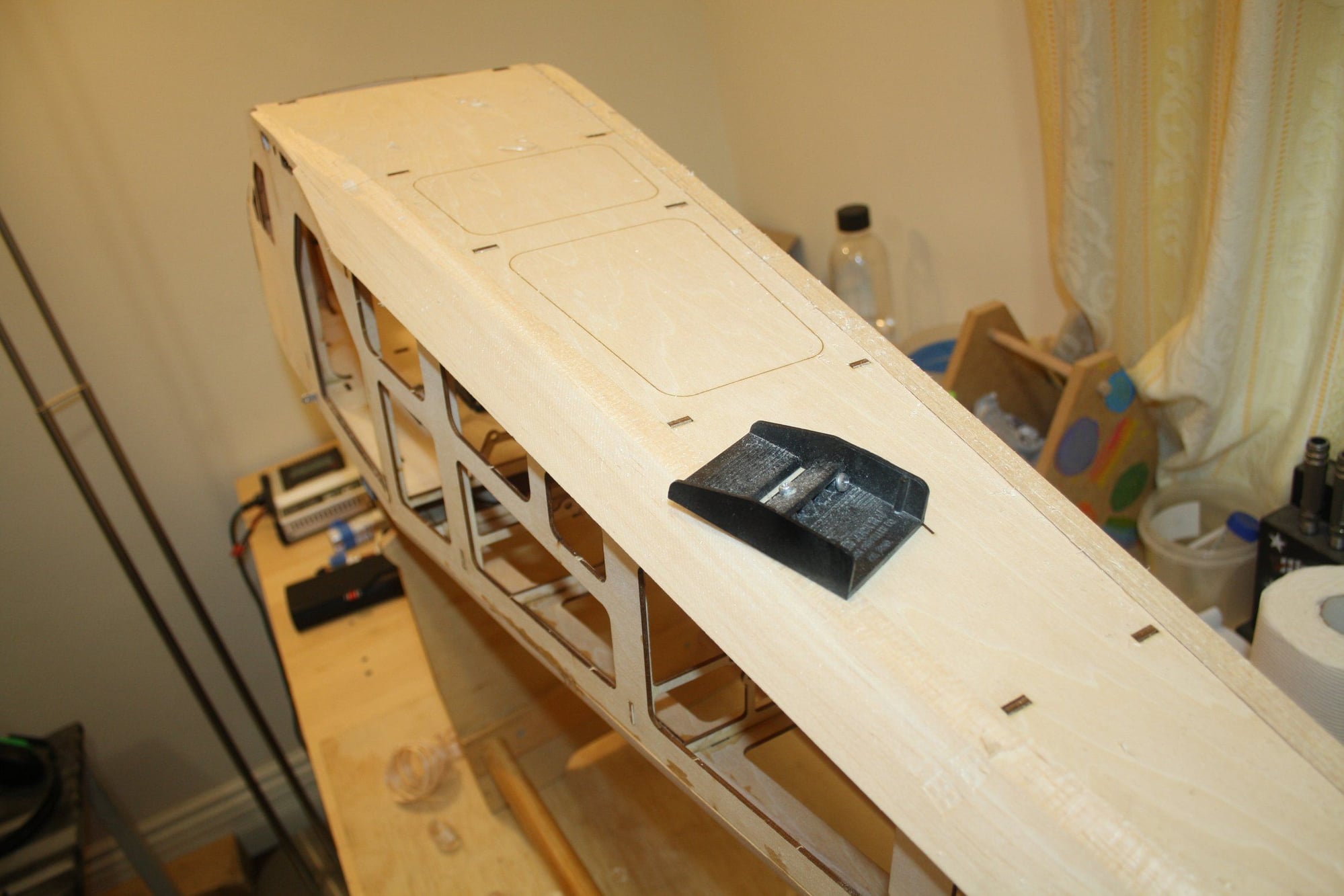
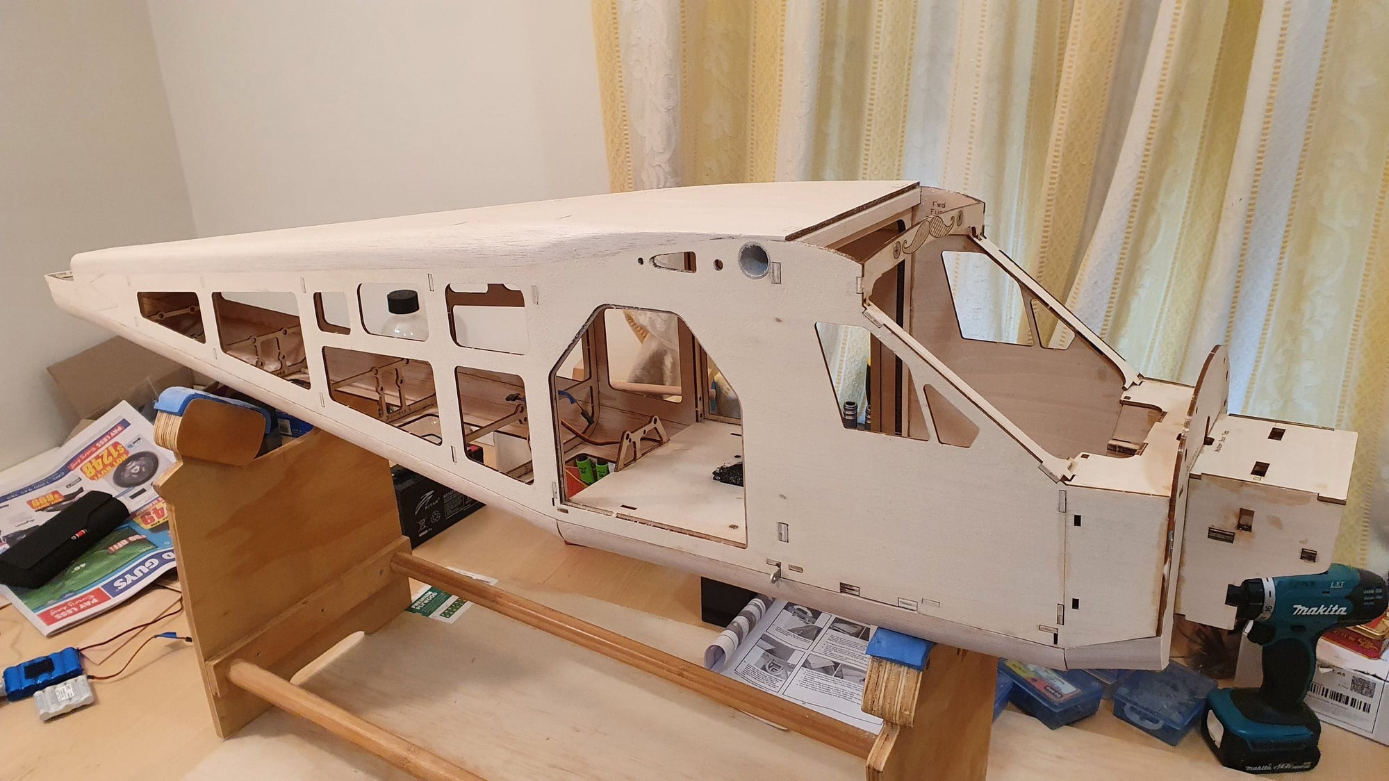
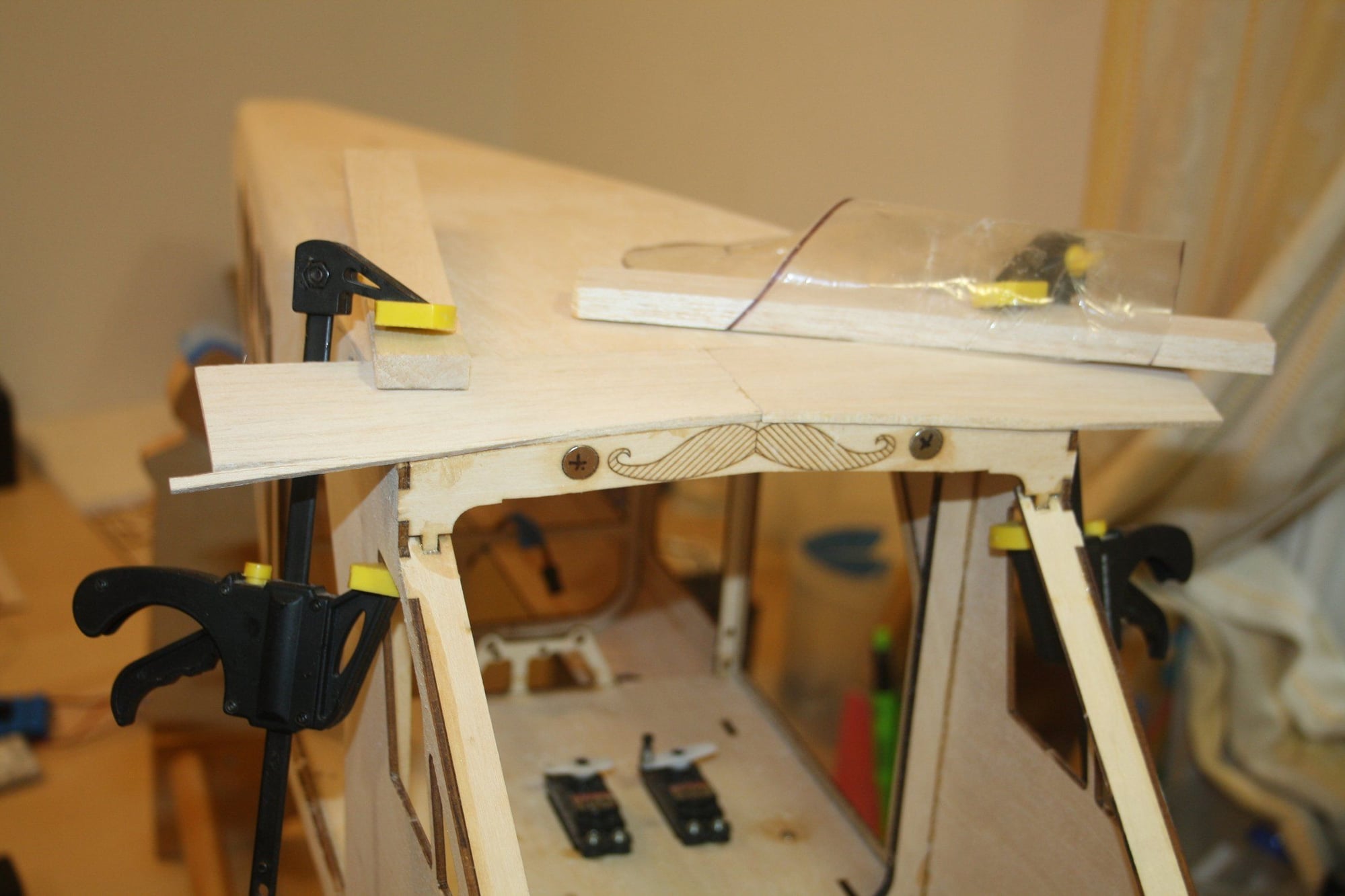
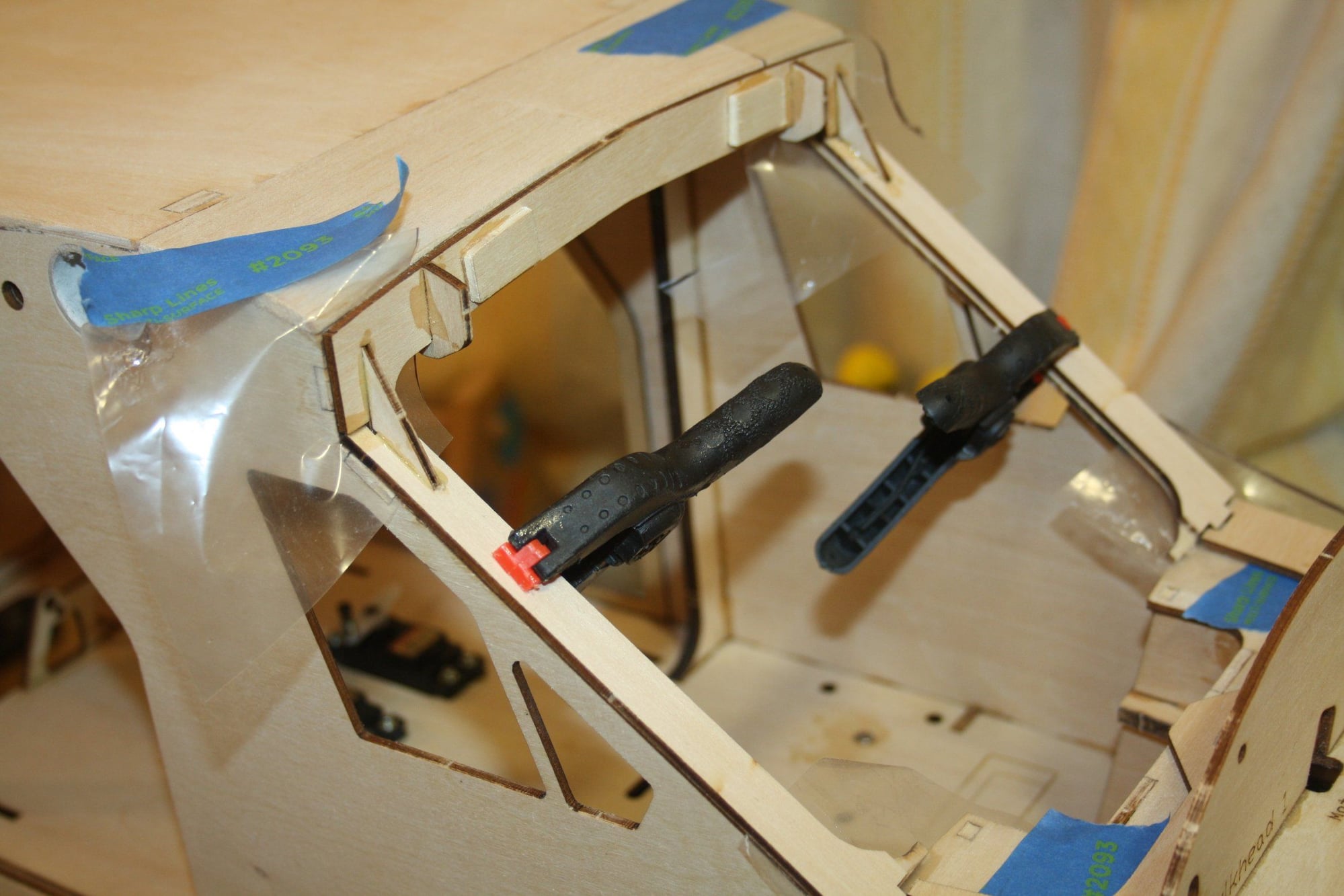
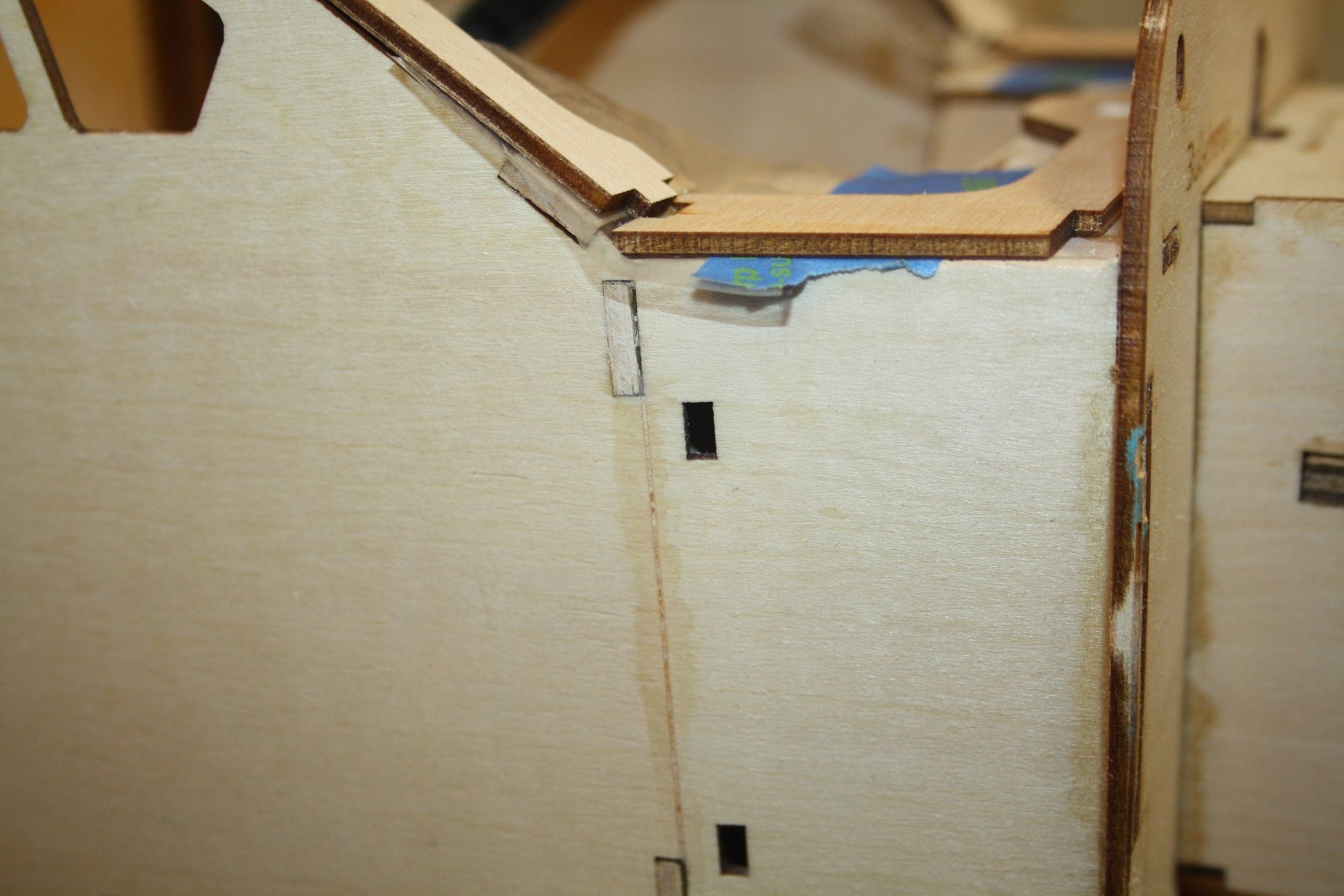
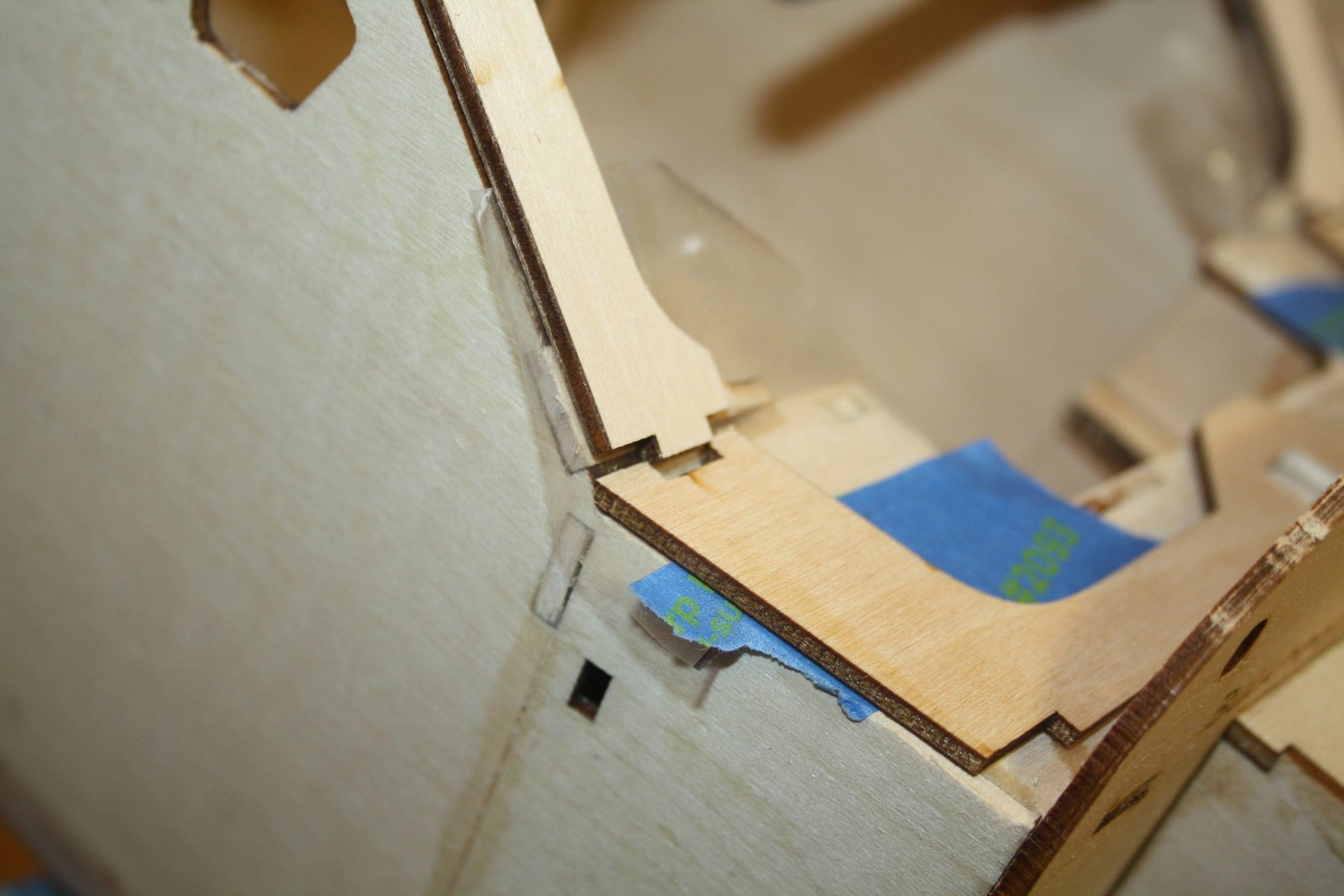
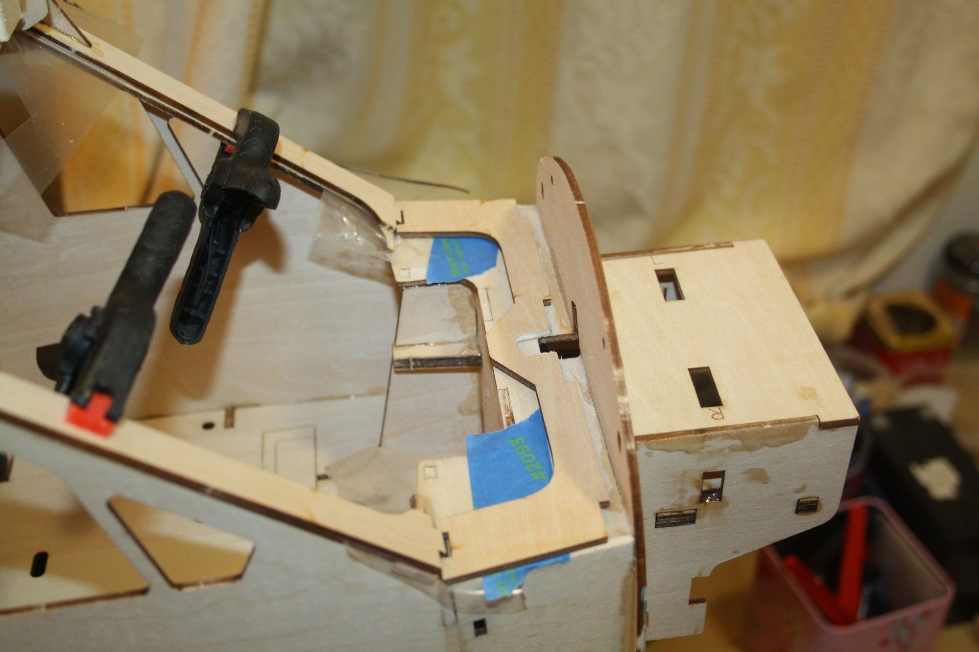
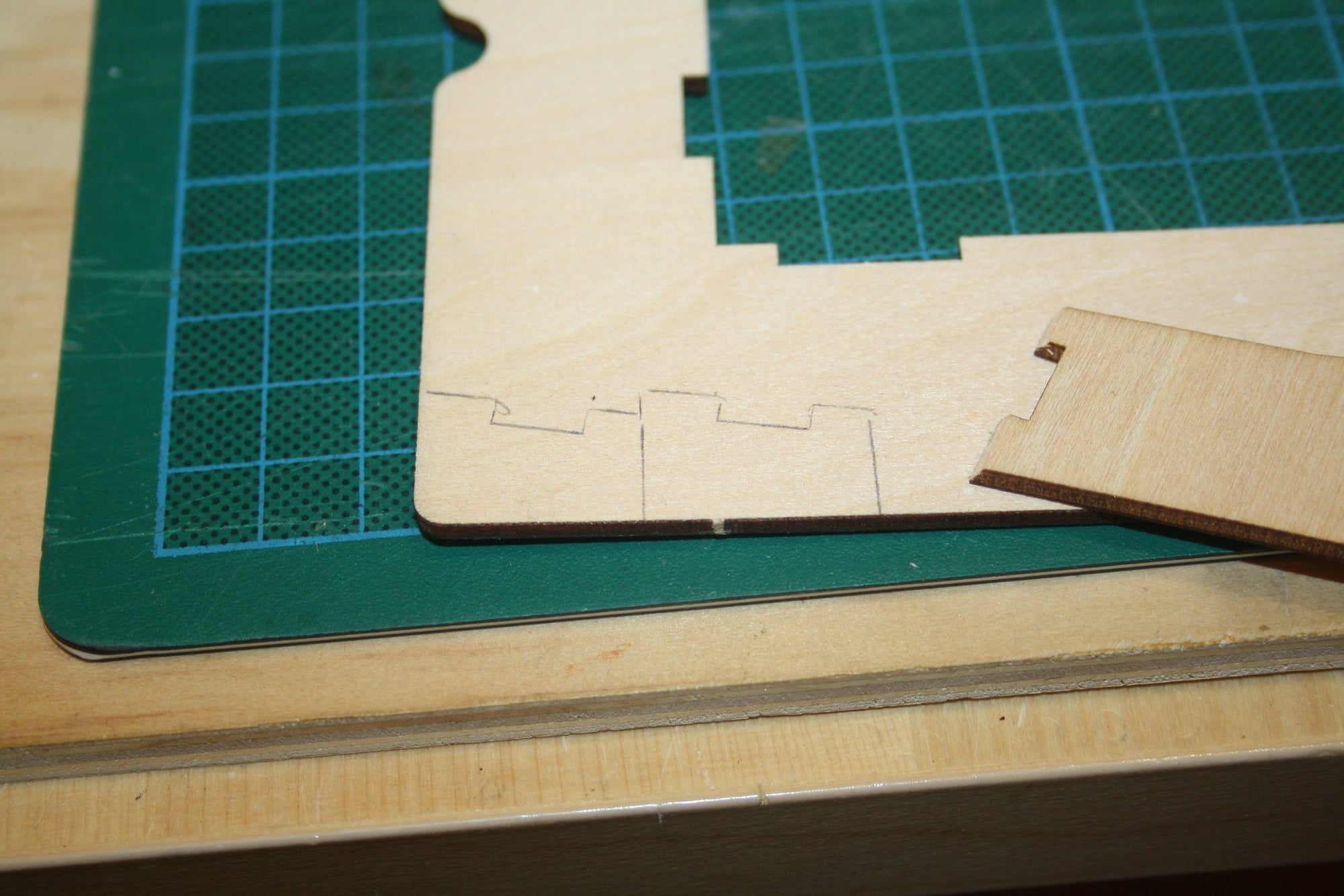
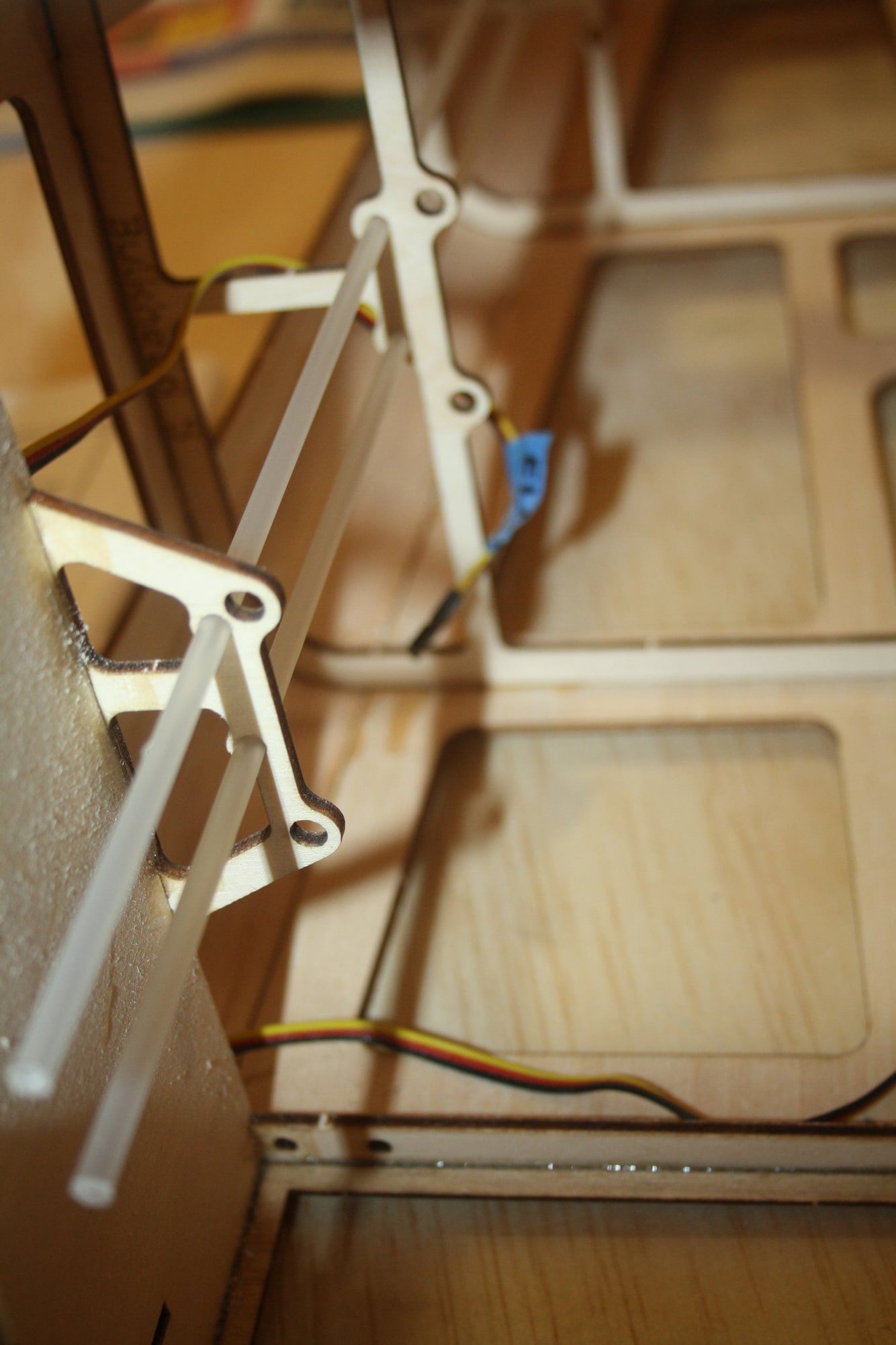
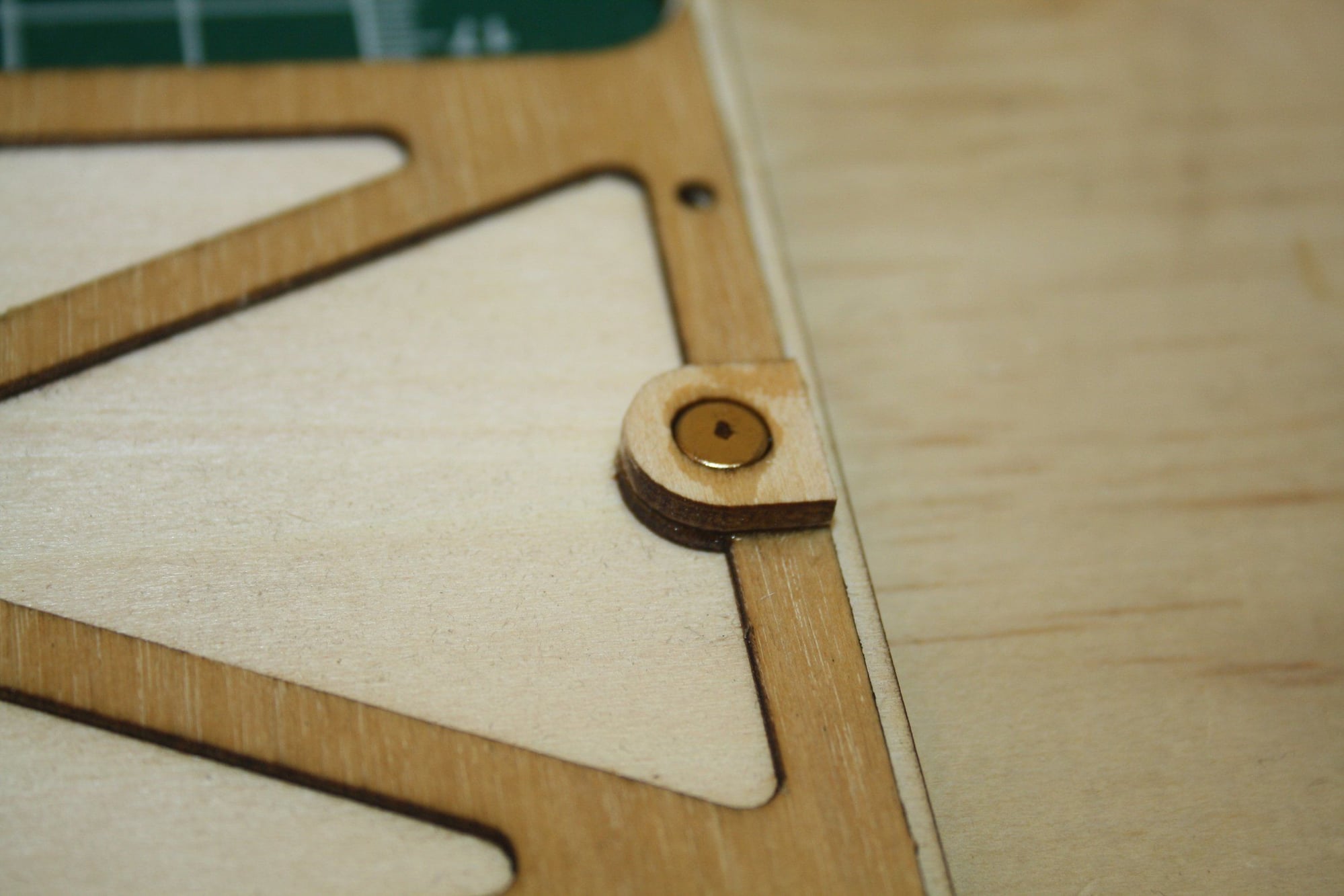
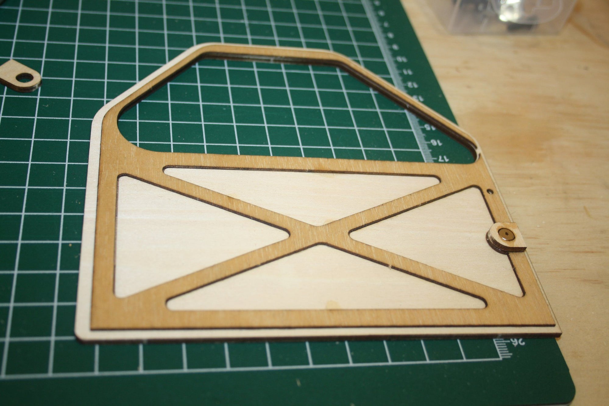
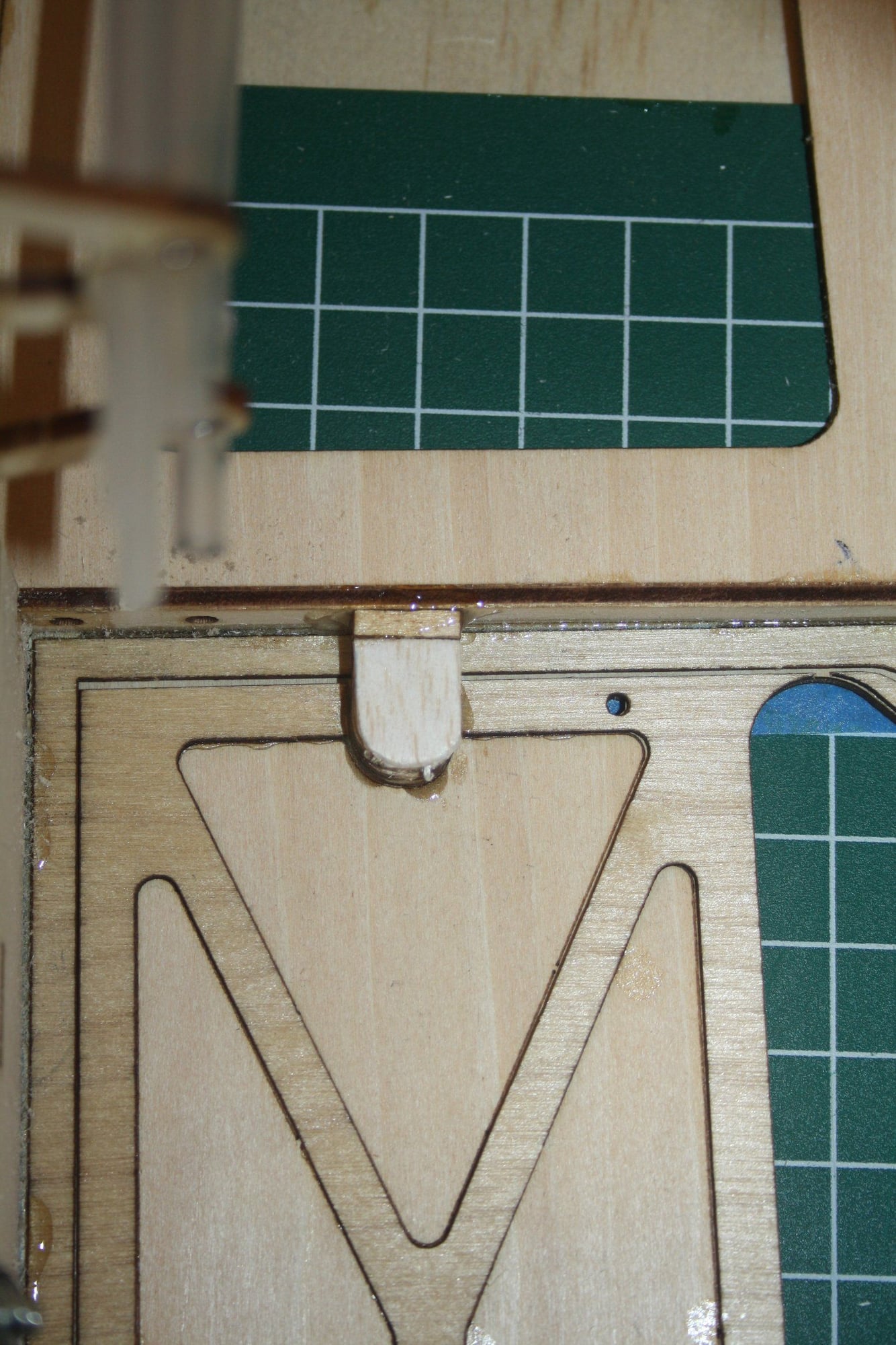
More of the fuselage construction, including the magnets for the front canopy frame and notching the side frames to allow bending at the front section.
Cheers,
Eran
Cheers,
Eran
 10-28-2022, 03:22 AM
#58
Thread Starter
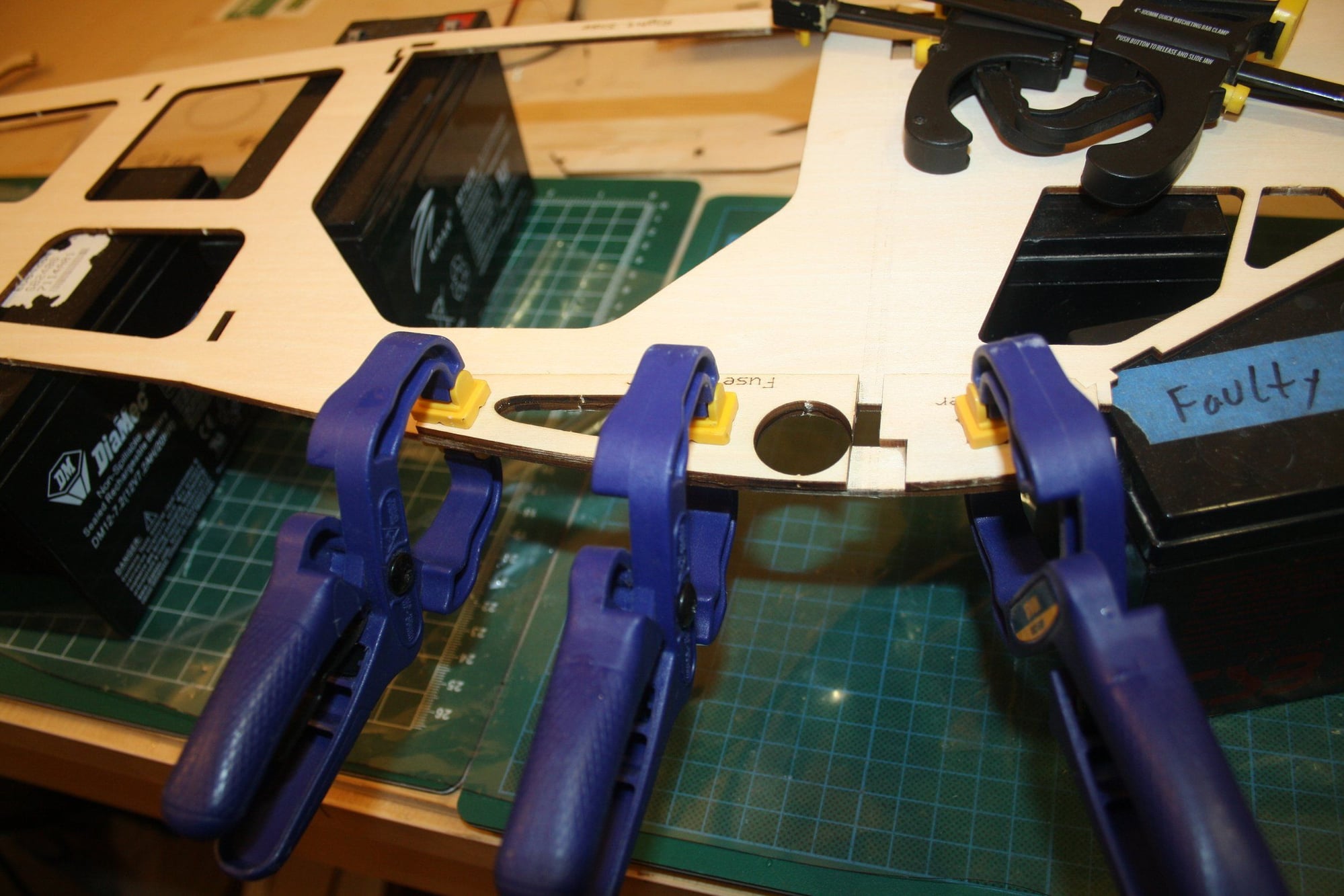
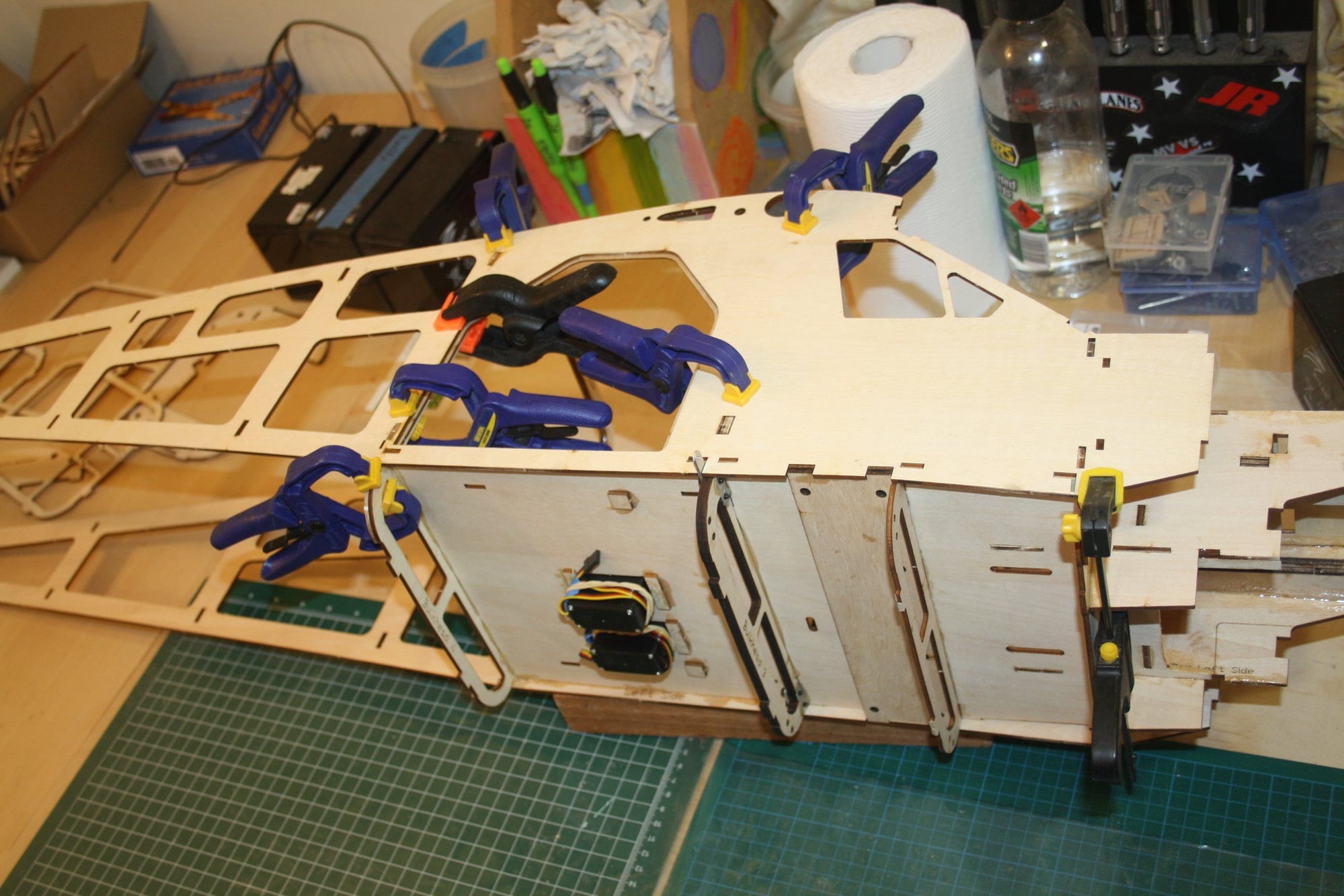
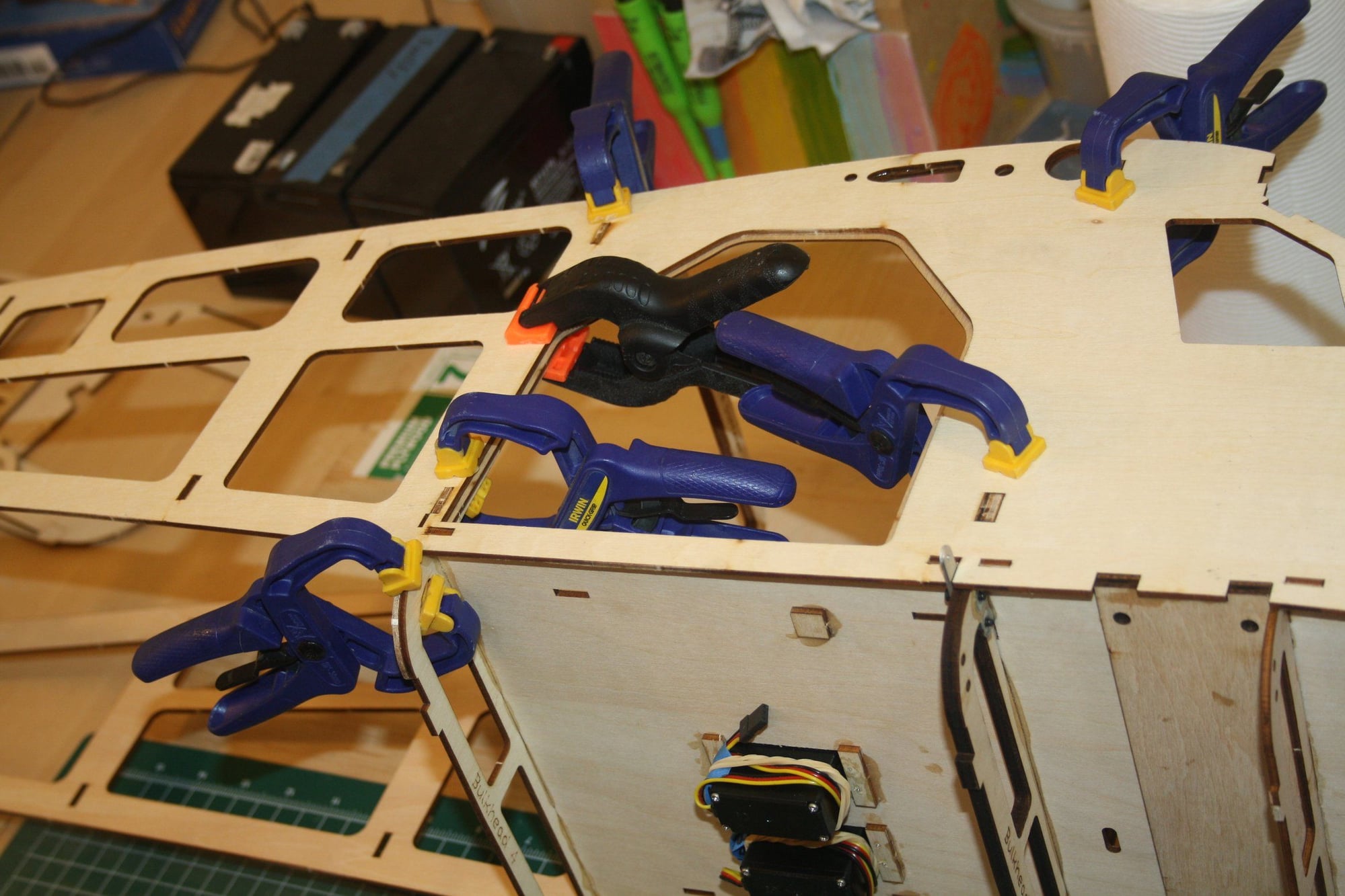
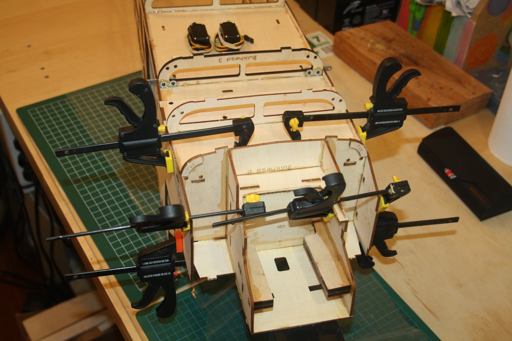
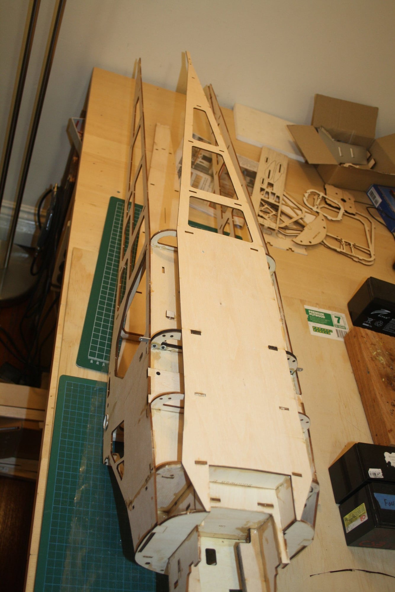
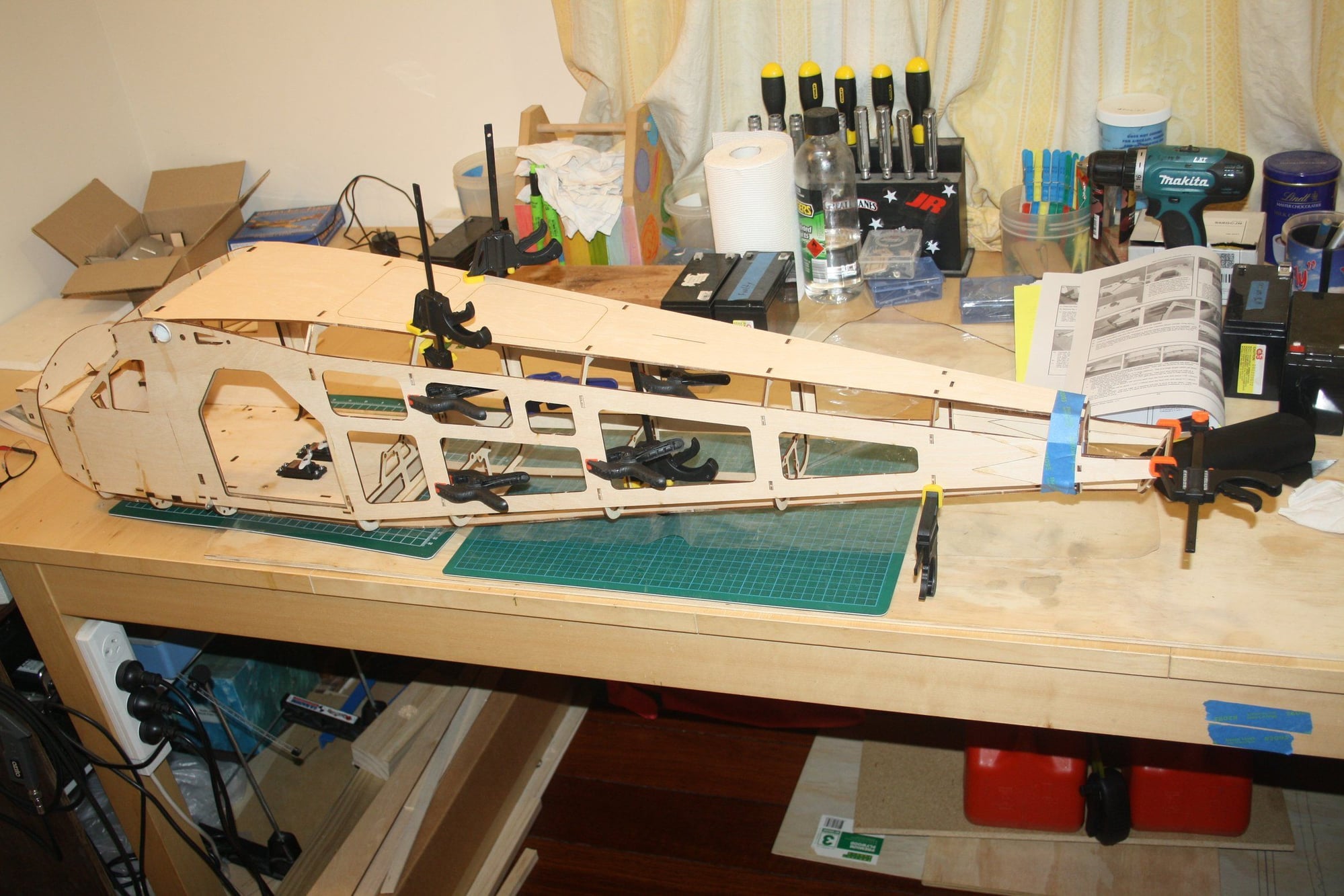
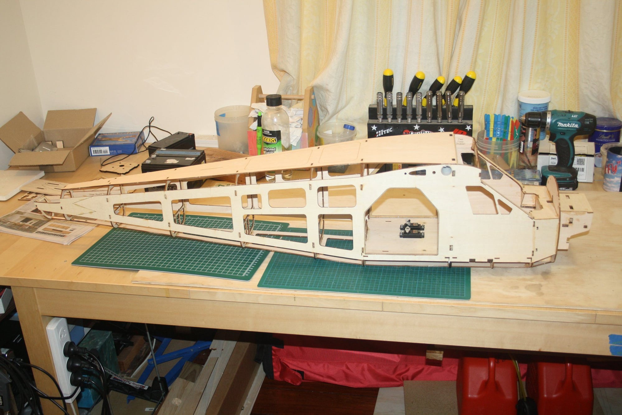
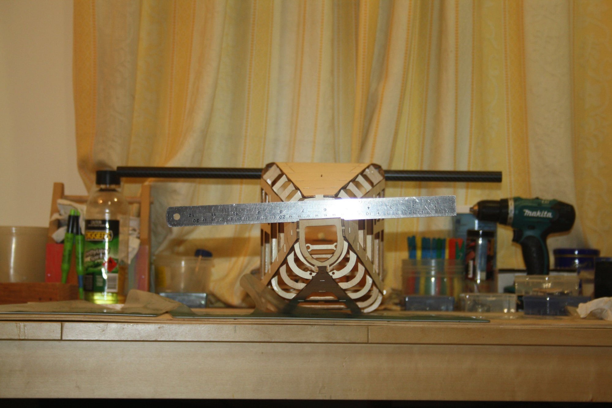
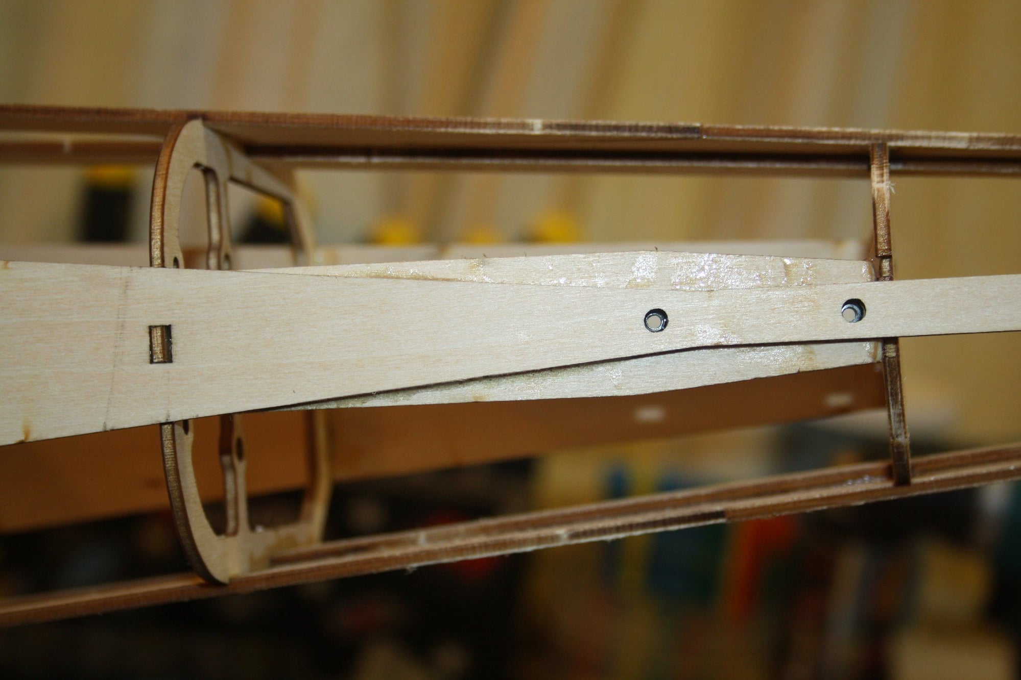
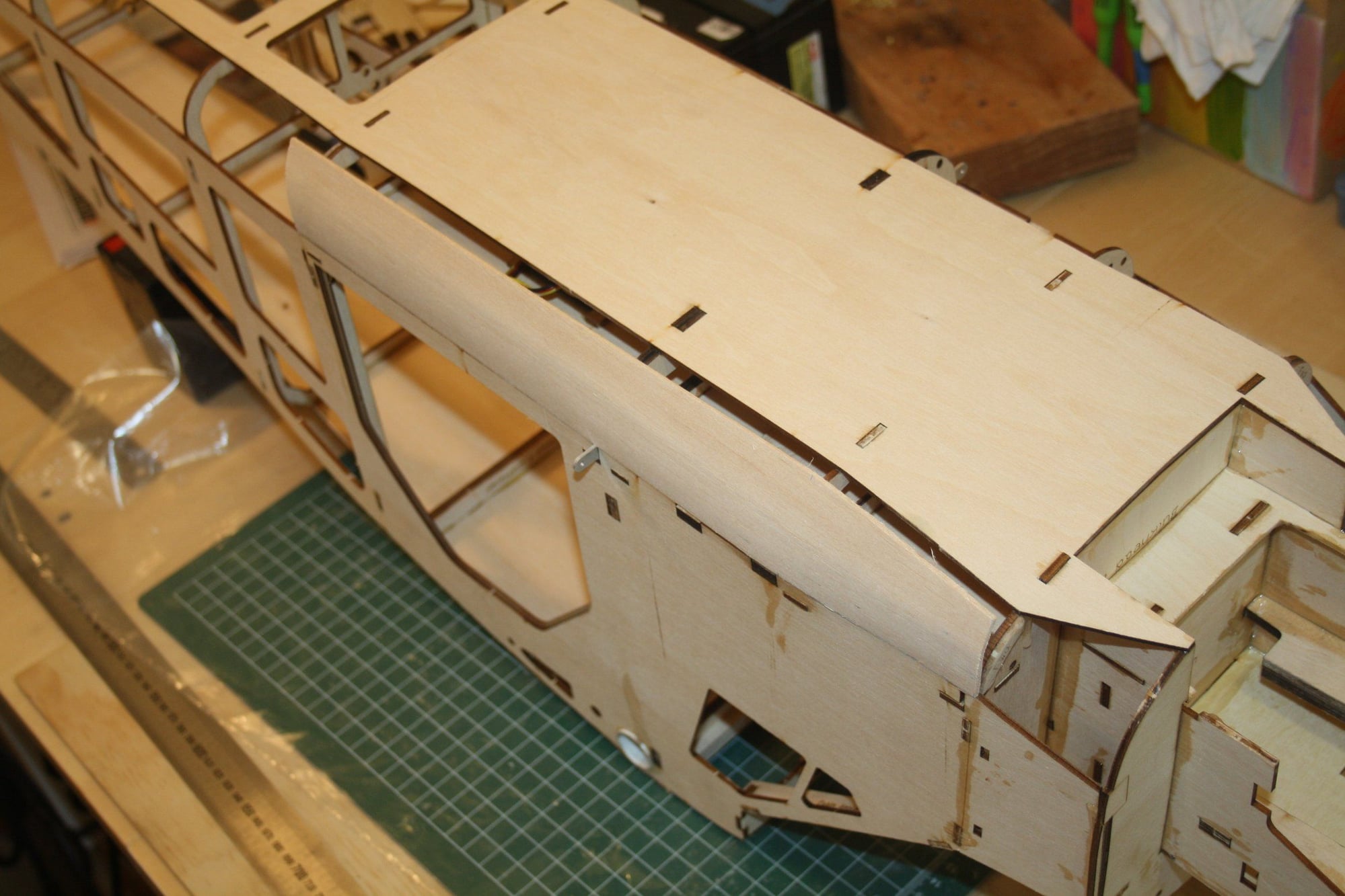
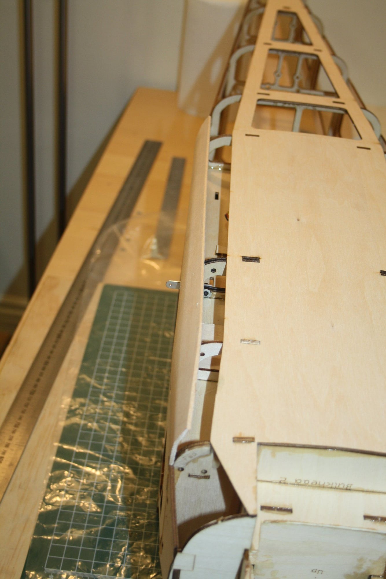
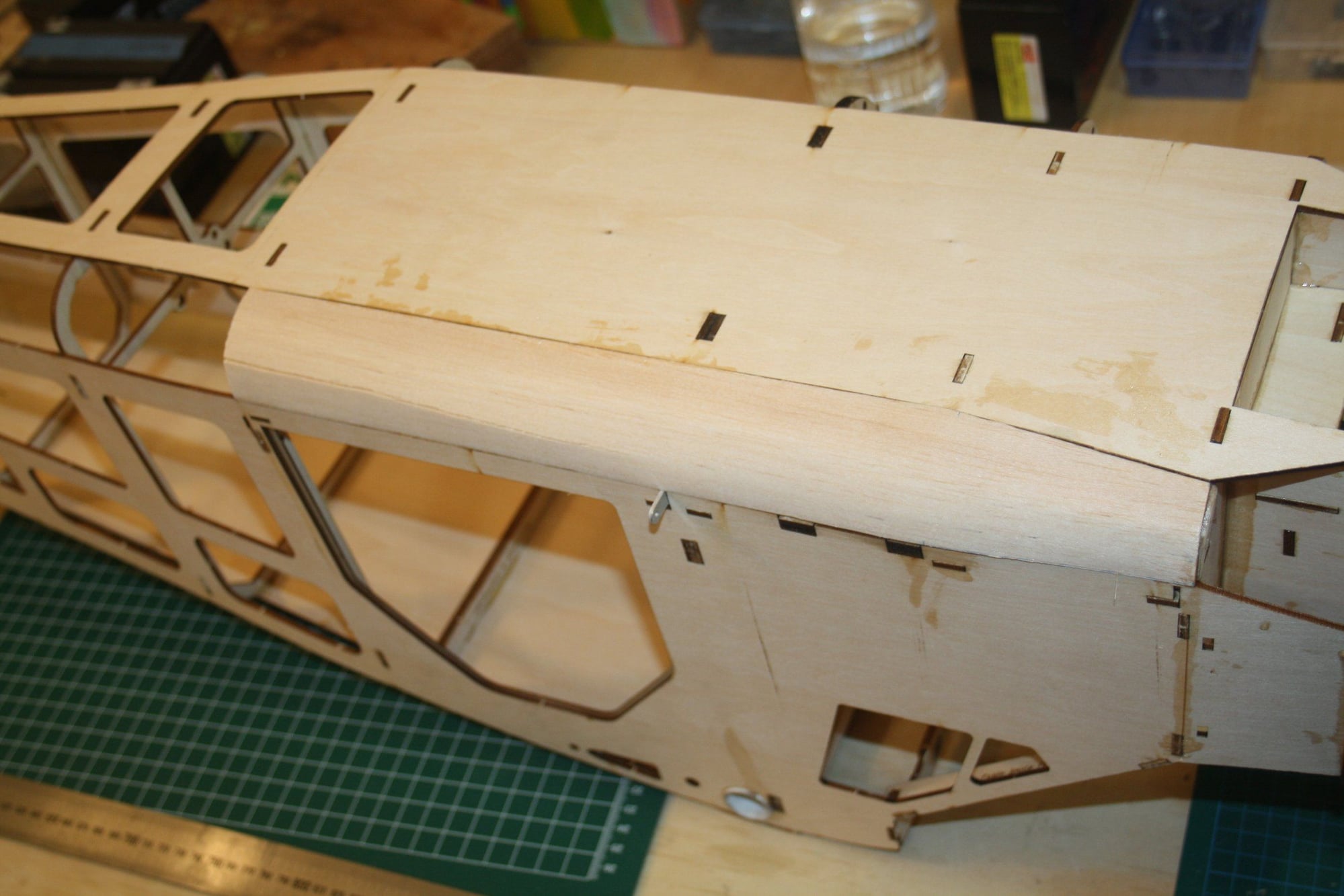
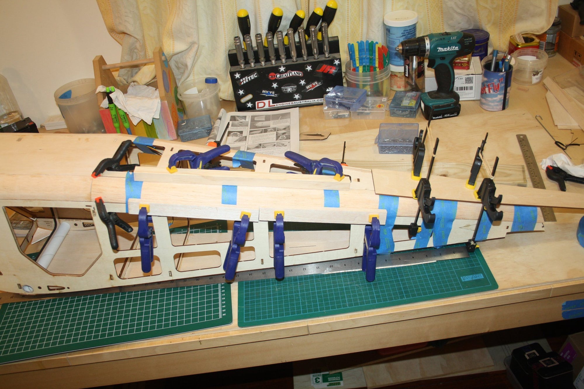
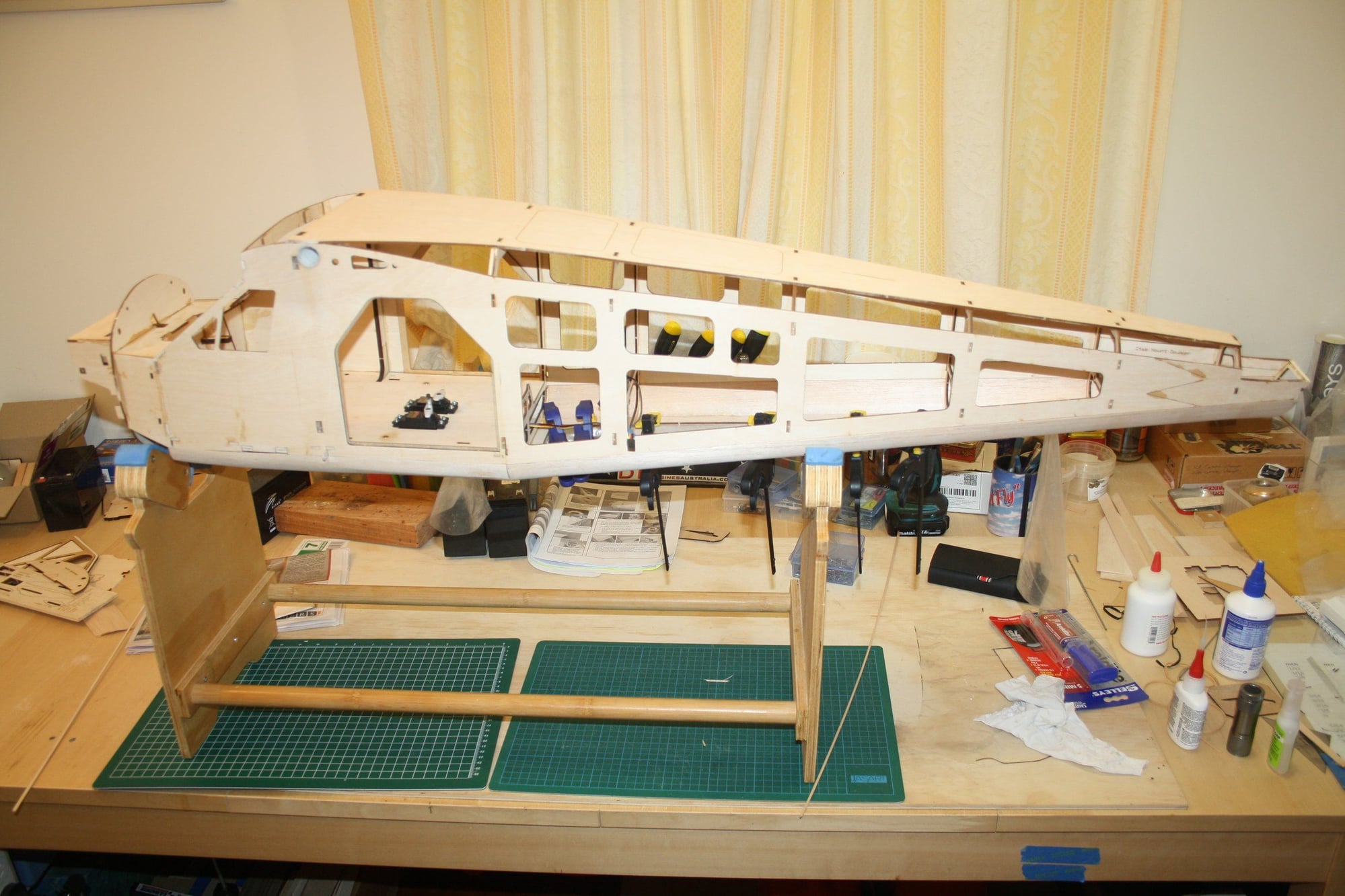
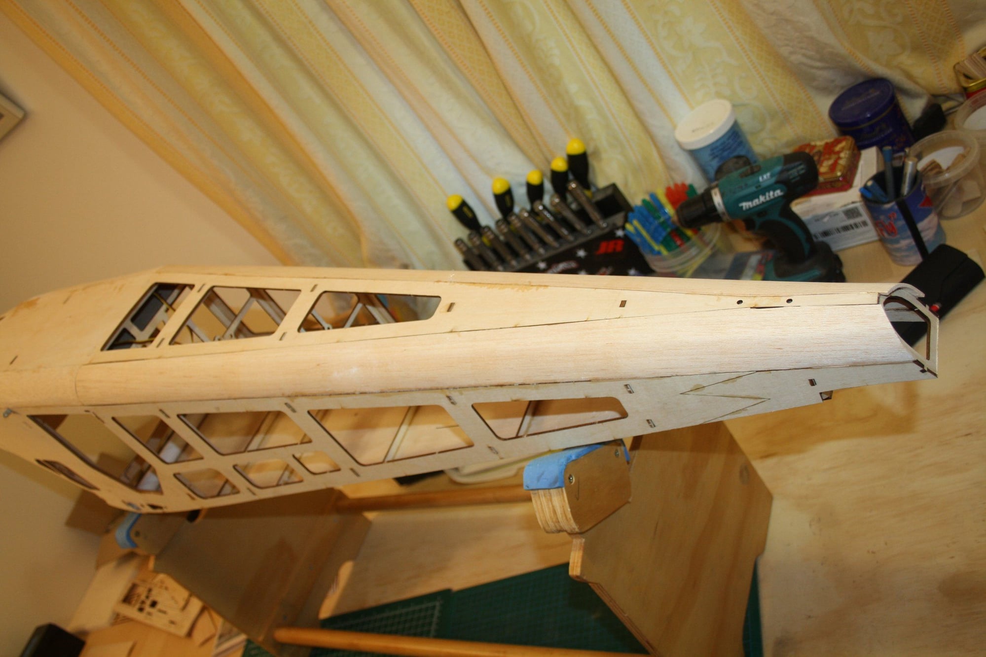
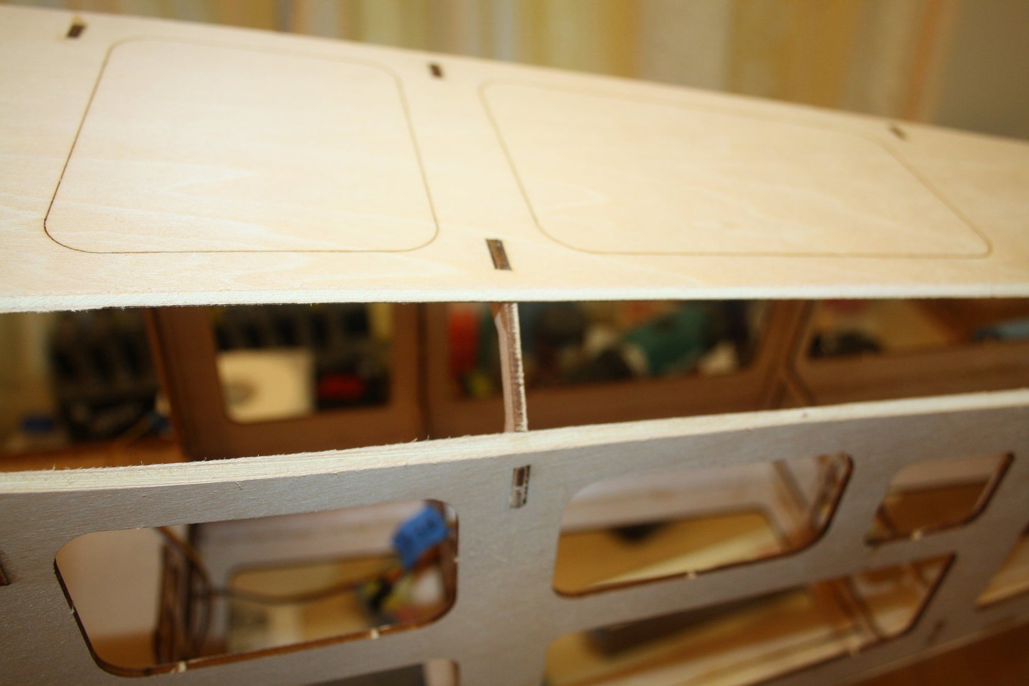
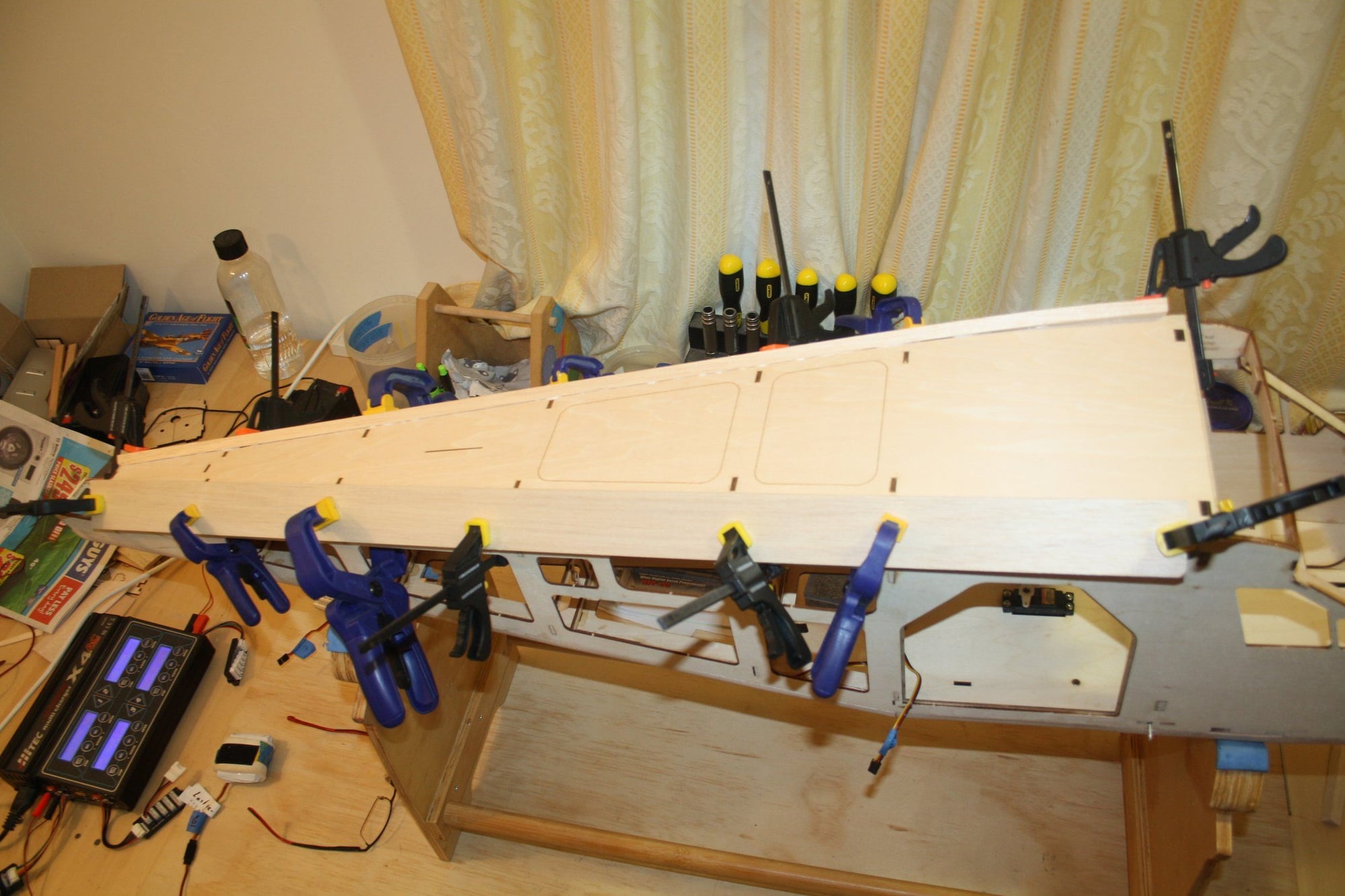
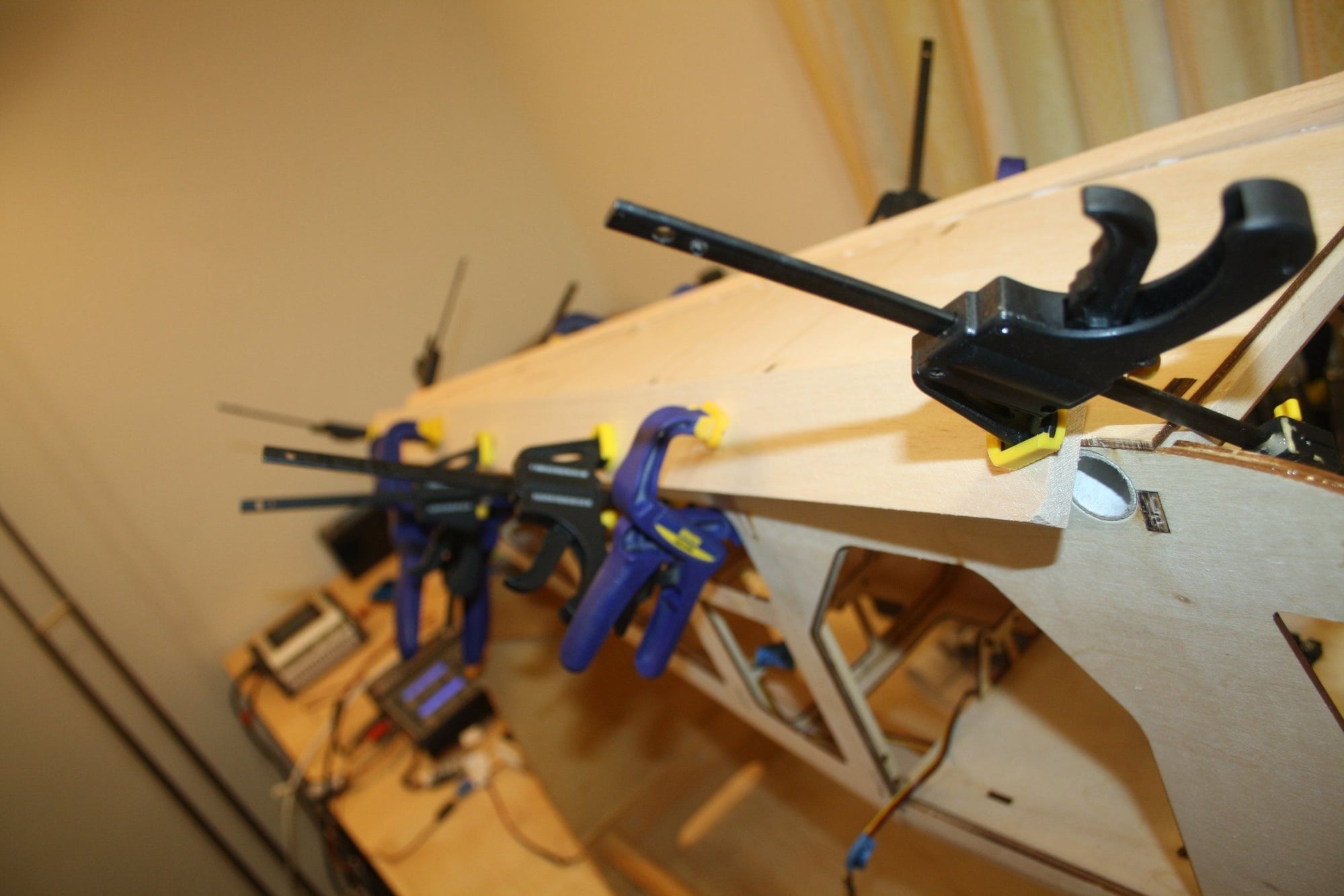
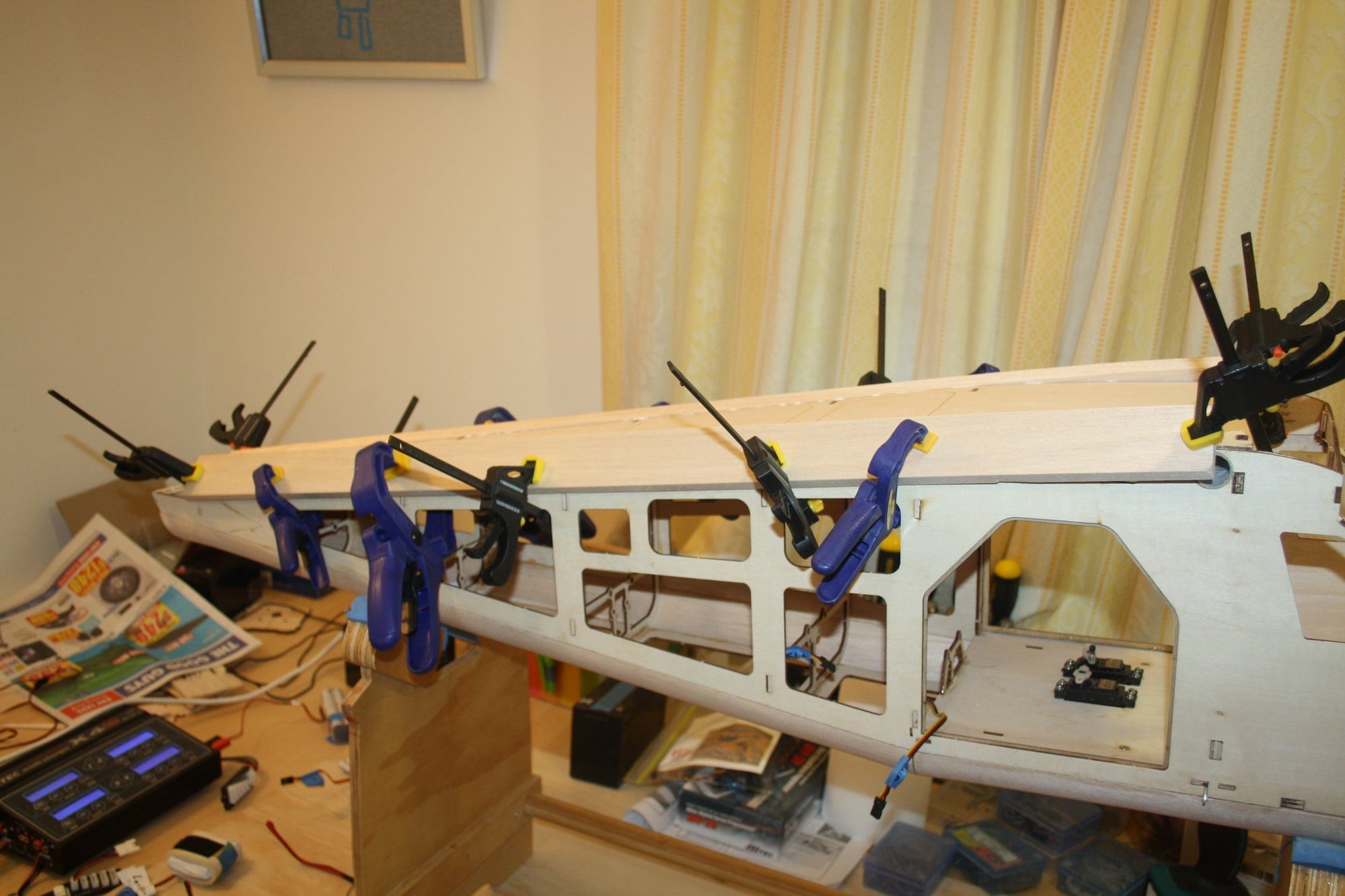
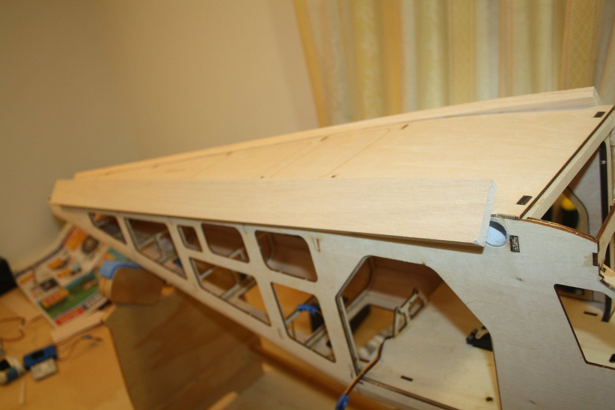
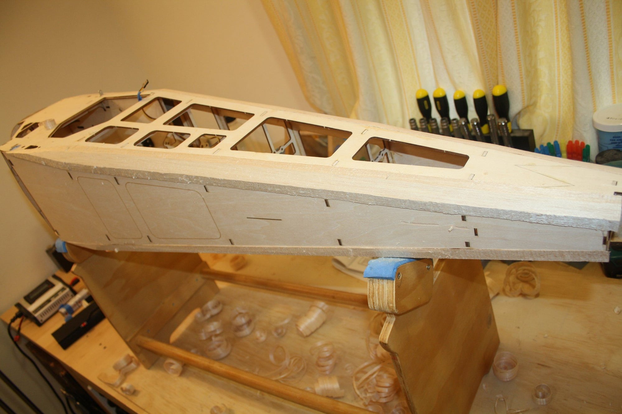
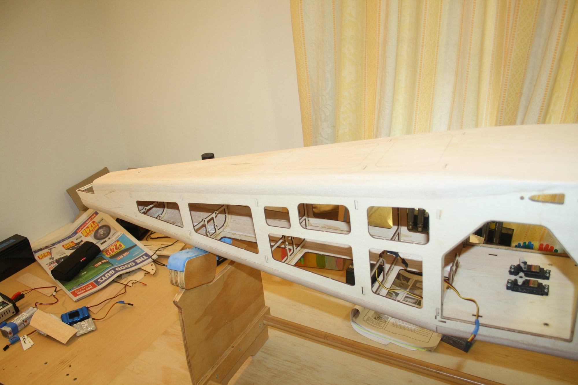
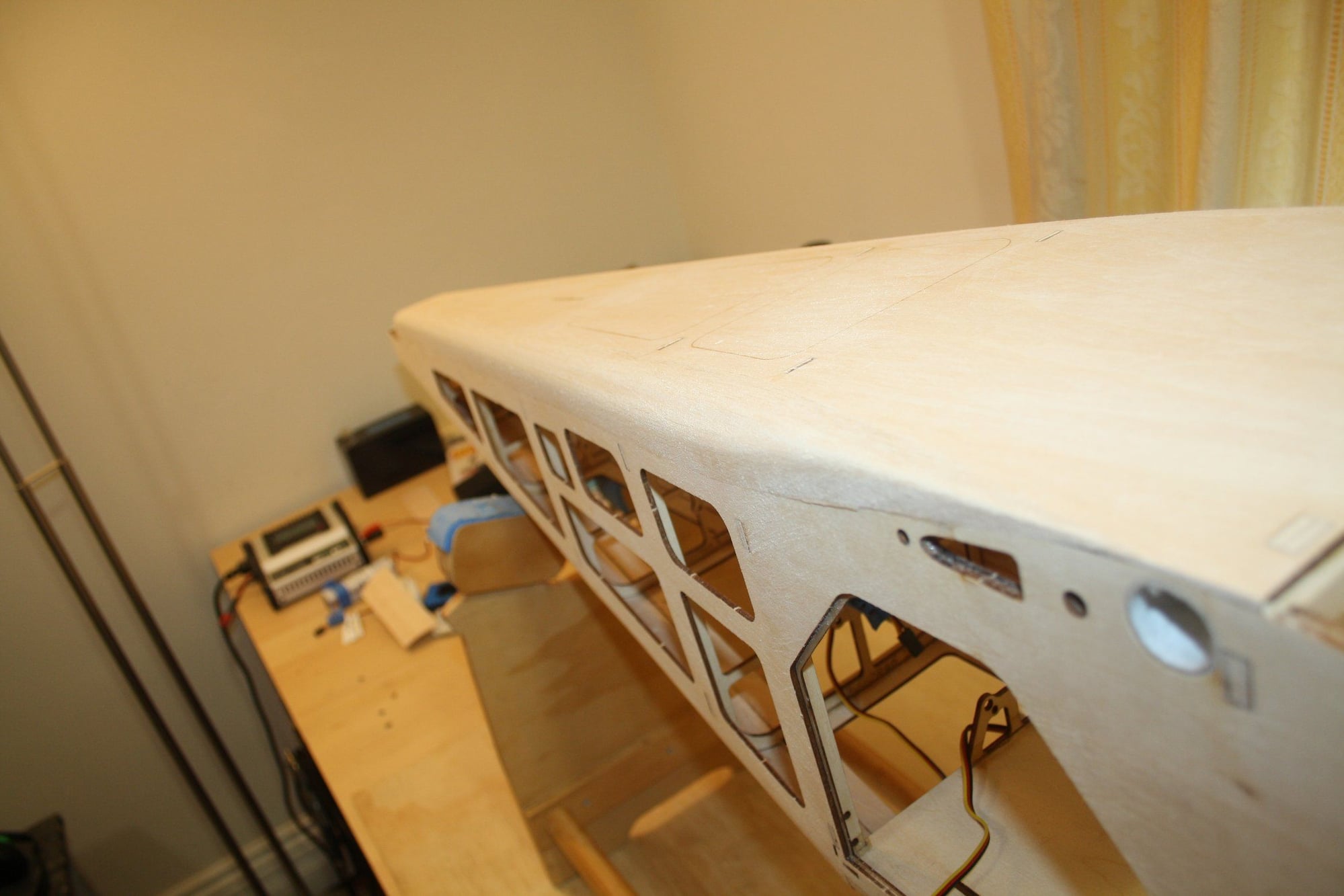
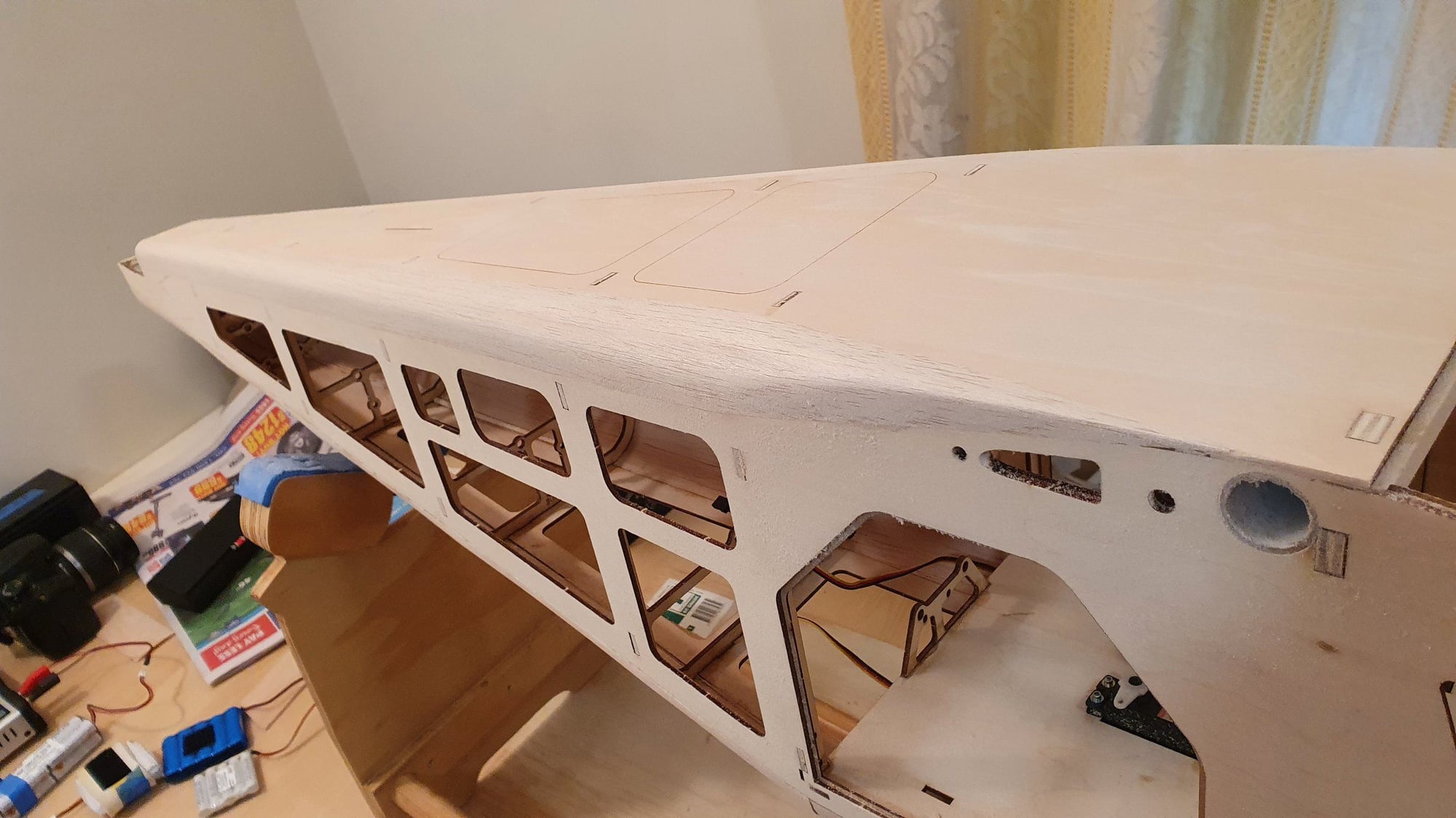
Completing the fuselage top and realising how twisted the structure is... How is it possible that by following the instructions and having a laser cut kit the builder manage to produce such a twist? NO traditional kit I had the pleasure to build have ever resulted in such a twisted fuselage, because there is constant emphasis on building straight, pinning to the board, using a straight edge etc... After the wing sheeting experience, I now completely lost my enthusiasm for this build.
Cheers,
Eran
Cheers,
Eran
10-28-2022, 09:04 PM
#59
step 34 in the manual has you tape the rear portion of the fuselage together before any glue is applied so that it can be aligned before being glued in place. It seems to me that there was enough slop in the tabs to center the stab to the wing tube before I glued mine. the only problem I had was the vertical fin, but I wasn't being careful and had to cut one side loose and re align it. You may have to use some debonder to loosen the joints and align the tapered portion. Hopefully the cabin was squared up as it was assembled and all the issues are only with the rear formers. Good Luck, keep pressing on, it flies good when done.
10-28-2022, 10:09 PM
#60
Thread Starter
bryanmick - Thank you for the comment. I am well advanced in the actual build compared to my updates. My aeroplane is in final equipment fitting stage.
My vertical fin had similar issue to yours, but I caught it prior to gluing.
I have no issue with these who found this kit acceptable. I found the instructions and the proposed methods of assembly the worse I have seen to the best of my memory. It is obvious to me that the designer has very little understanding of wood model construction techniques or he just didn't care.
Cheers,
Eran
11-06-2022, 03:08 AM
#61
Thread Starter
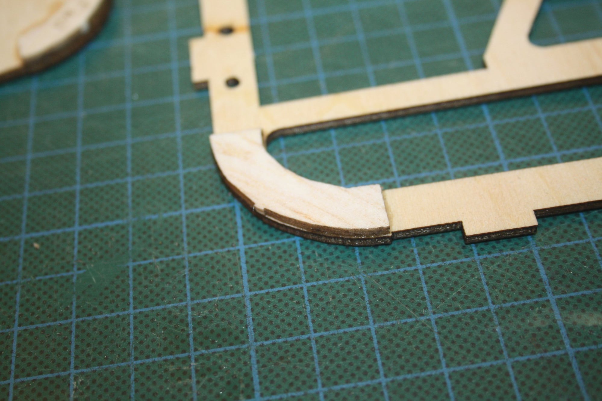
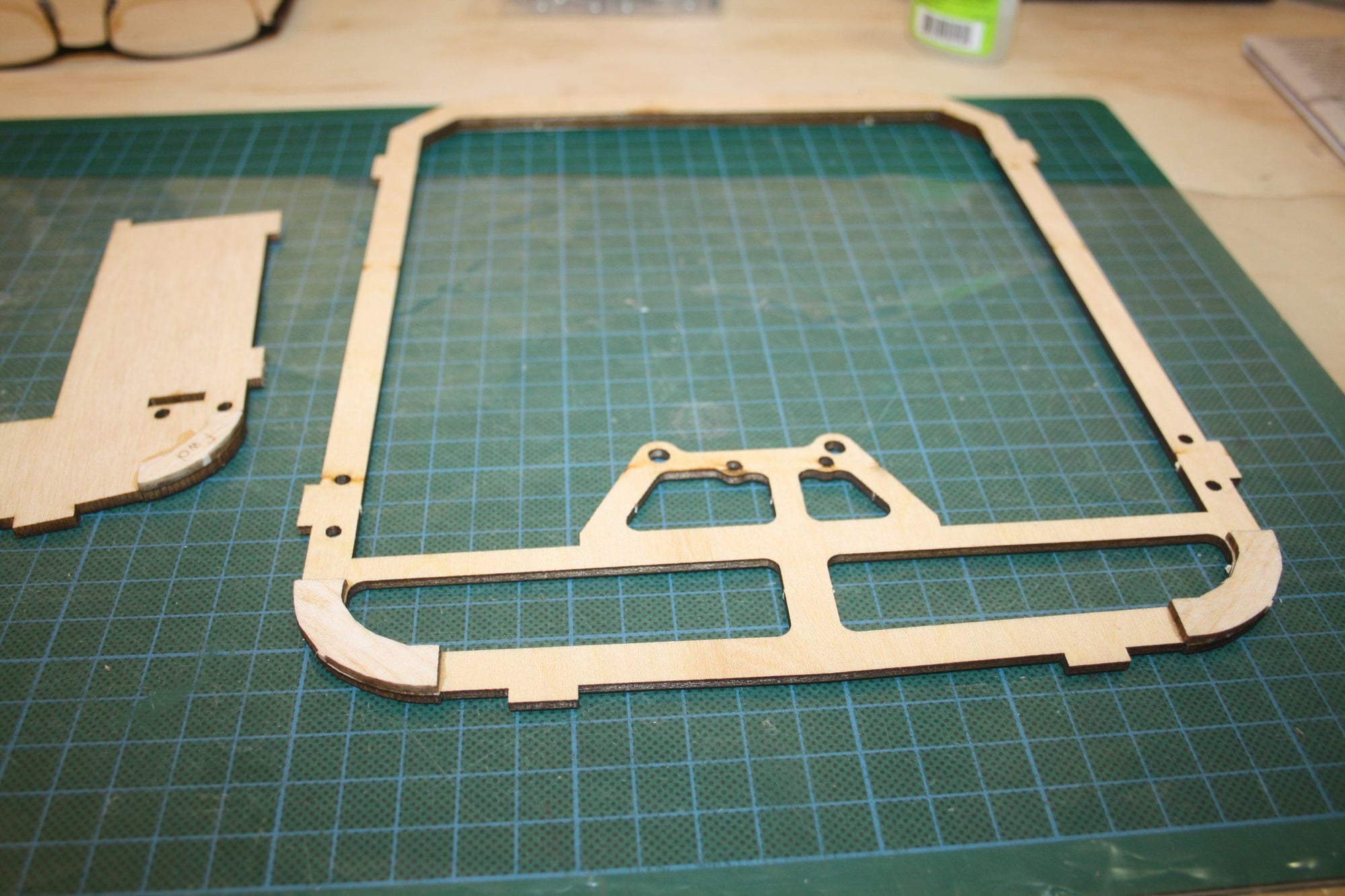
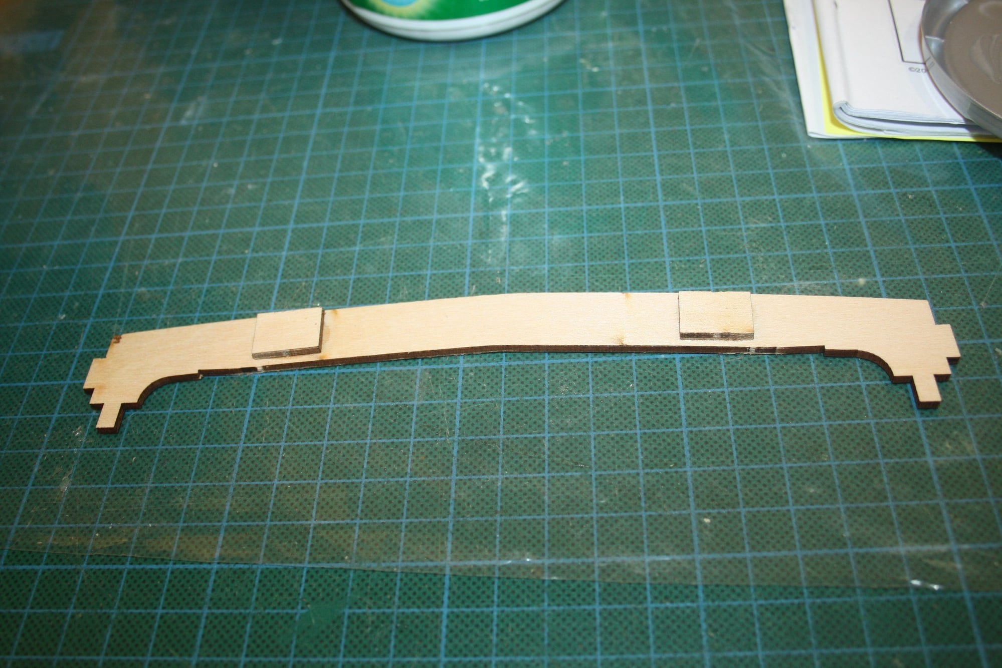
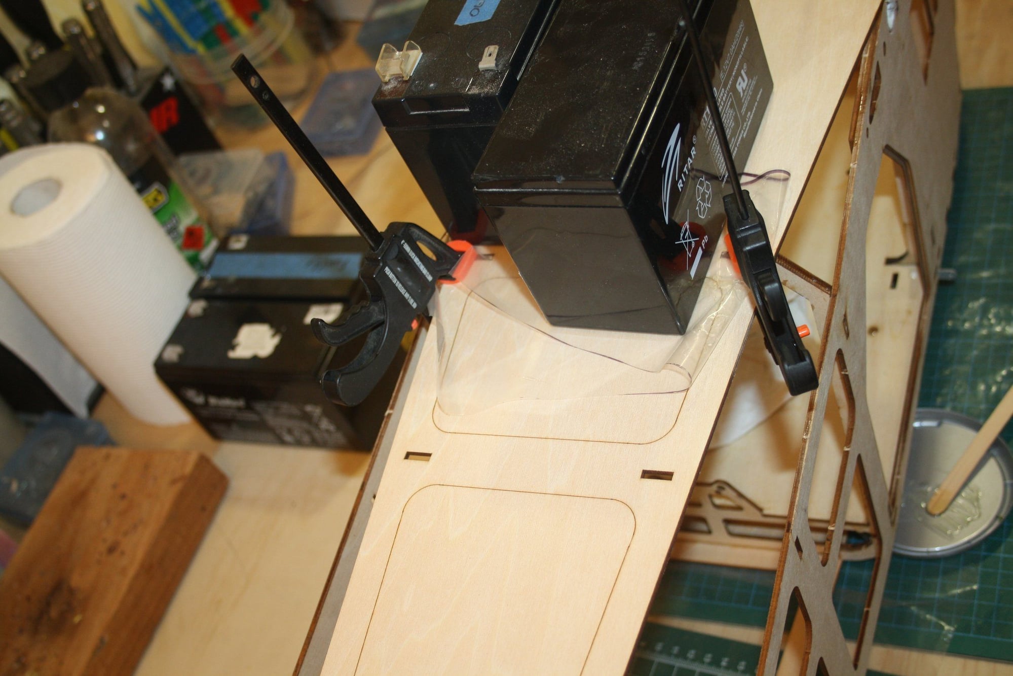
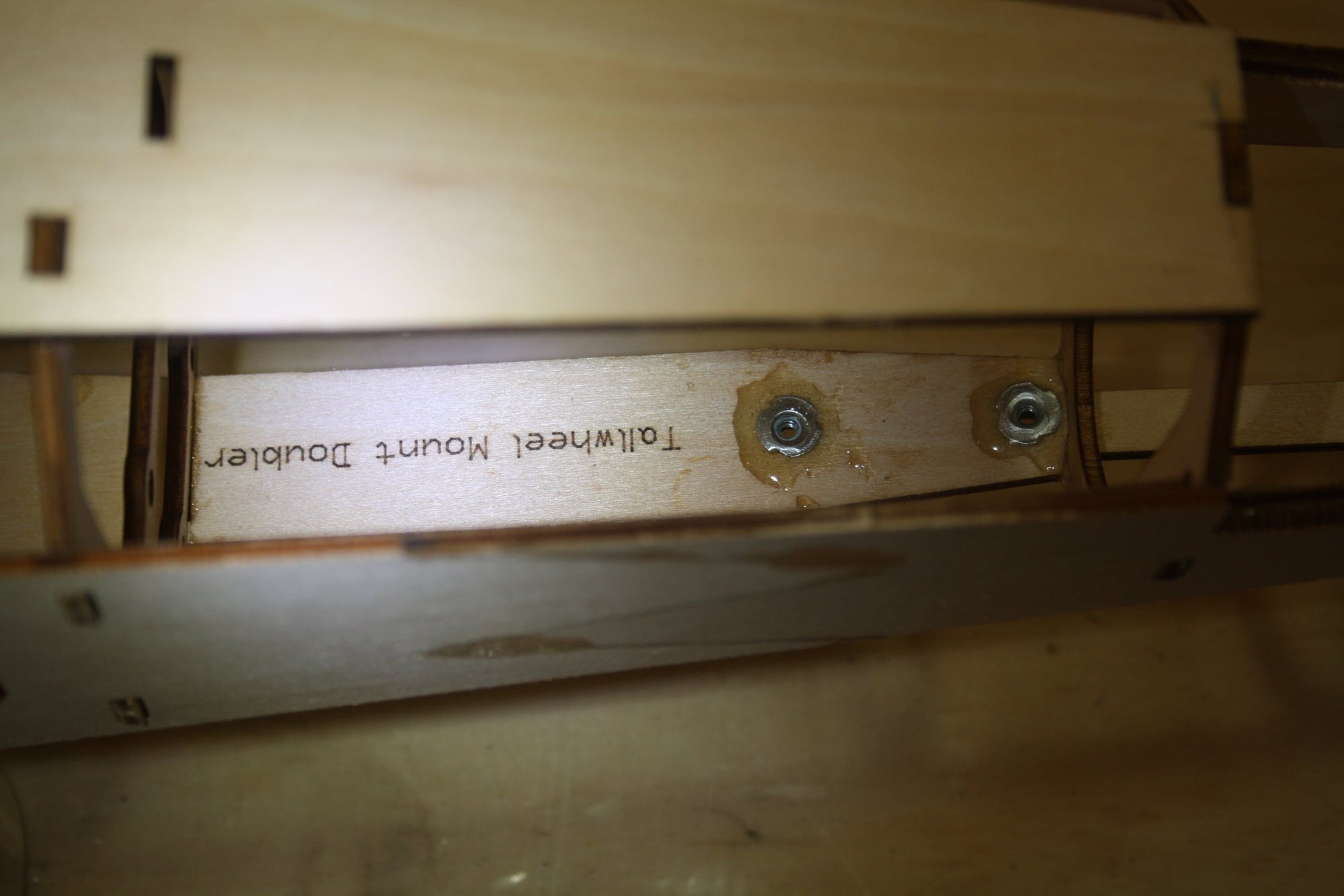
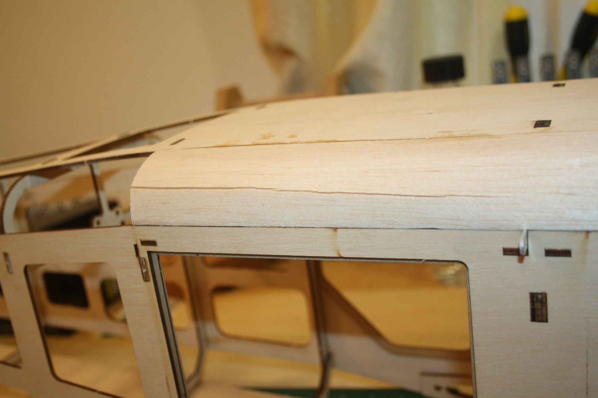
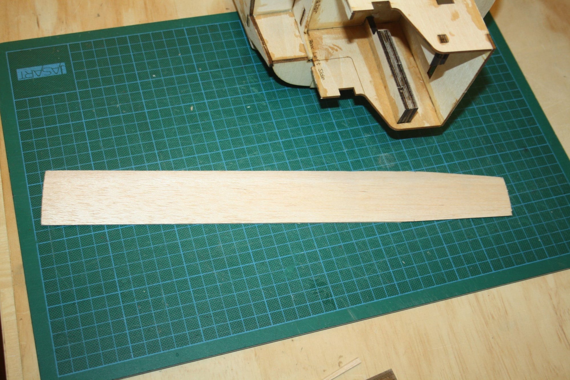
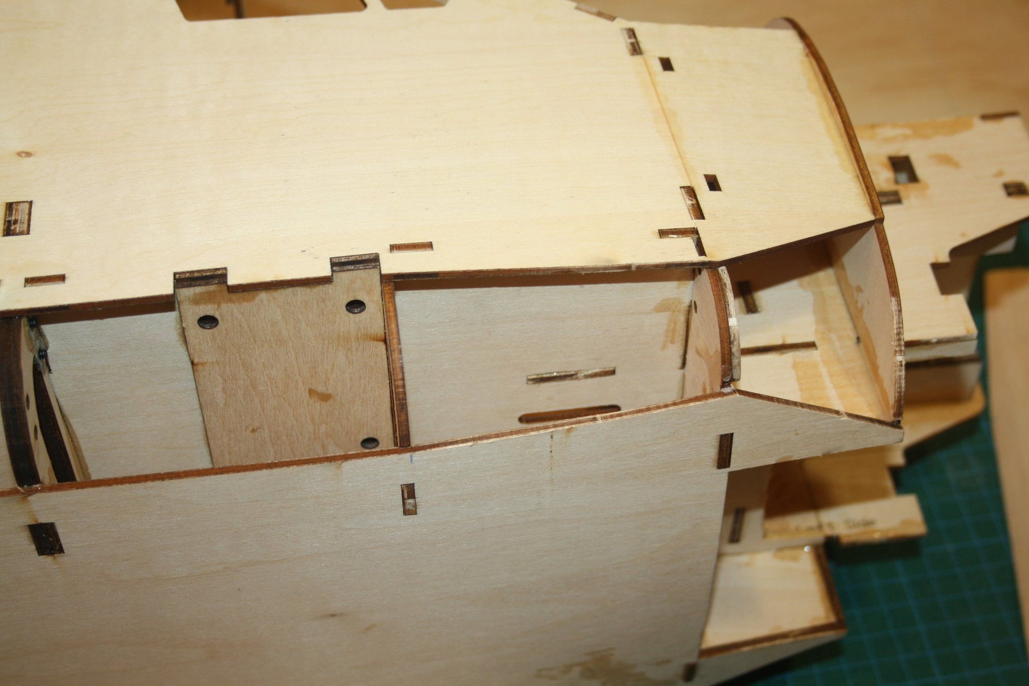
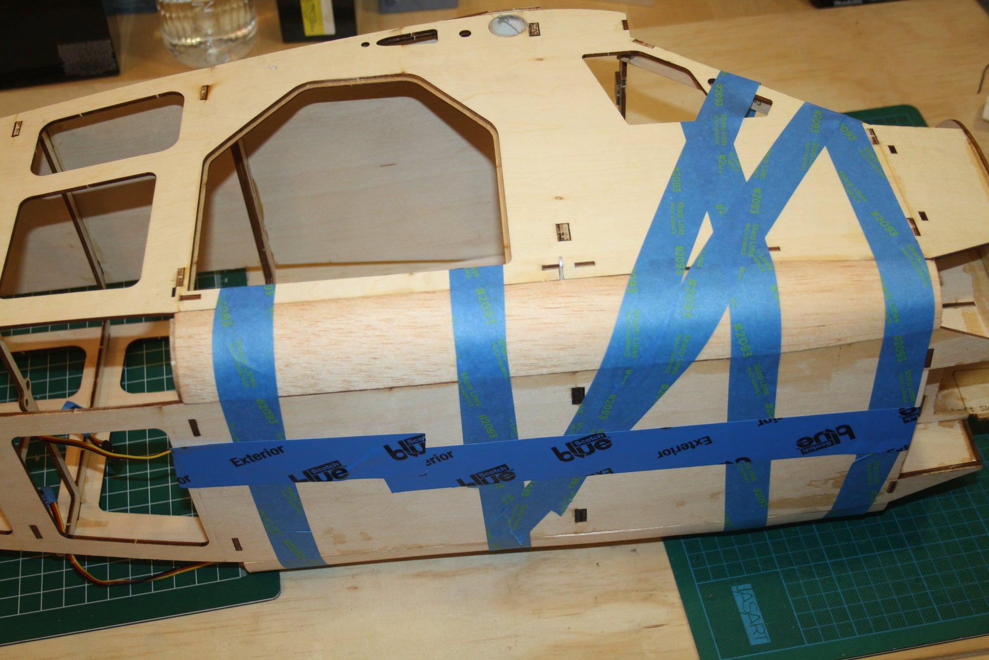
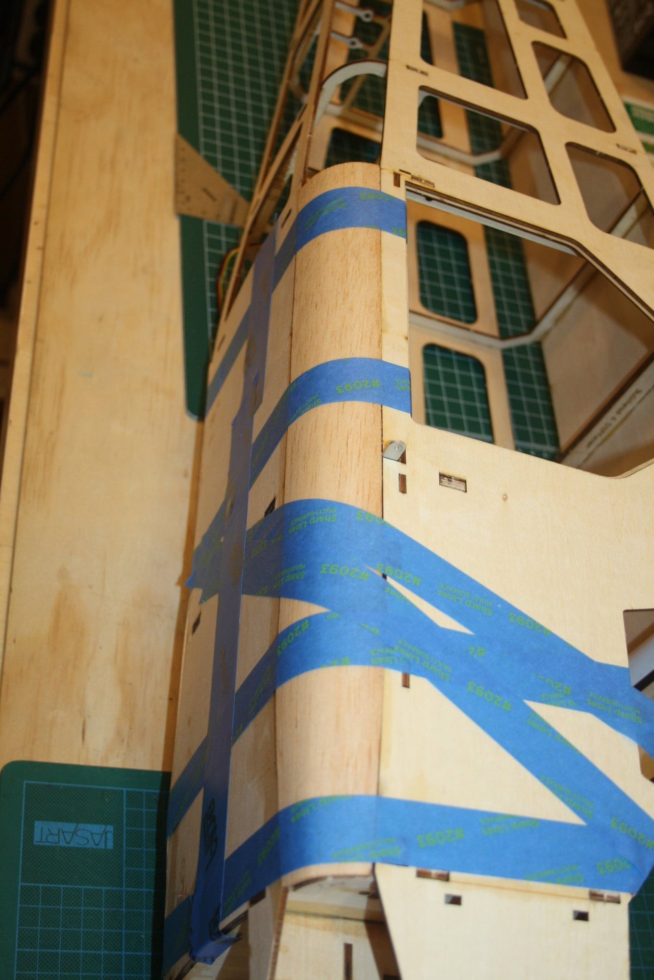
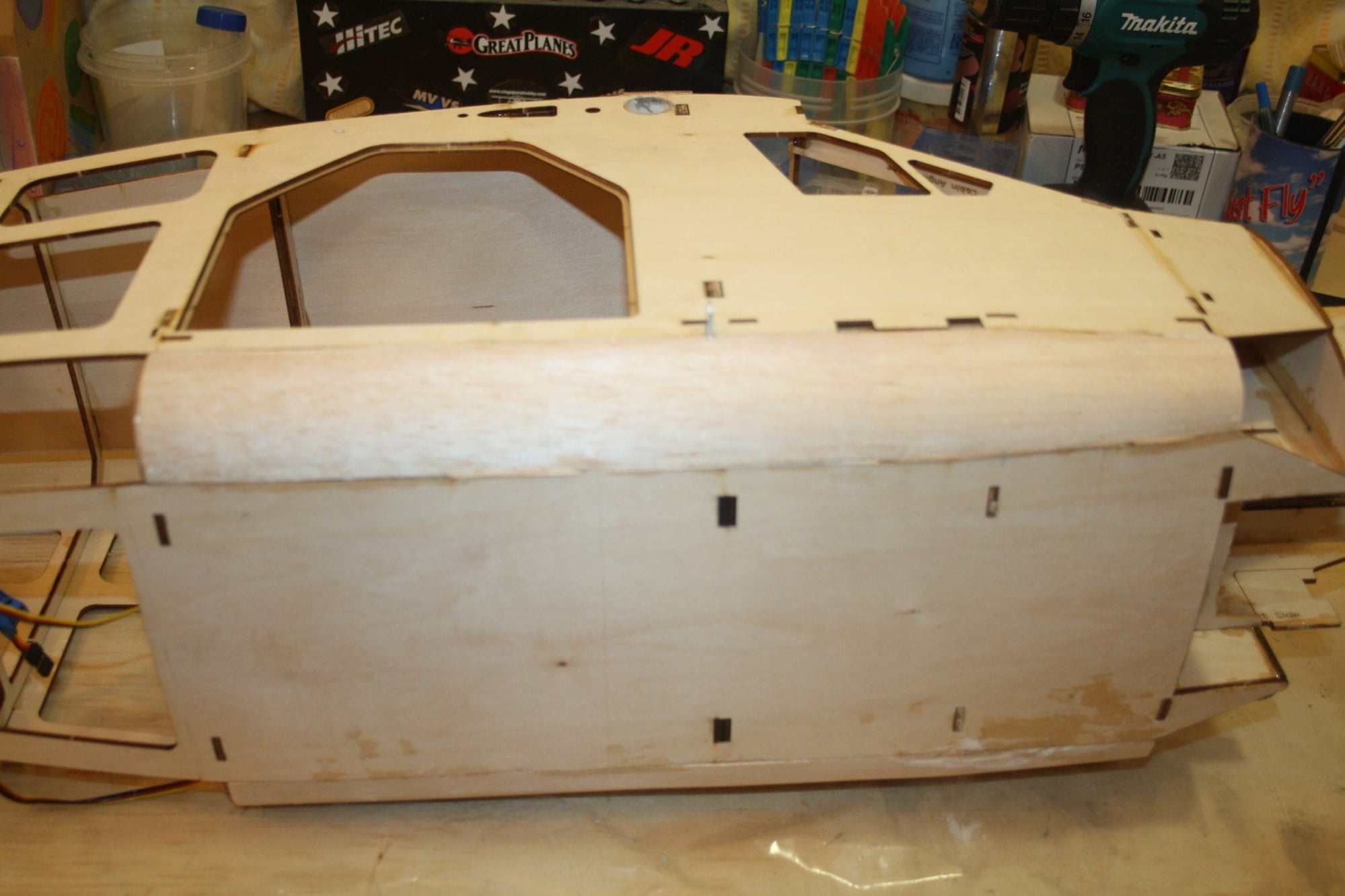
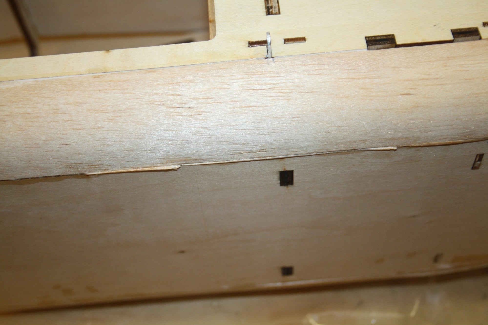
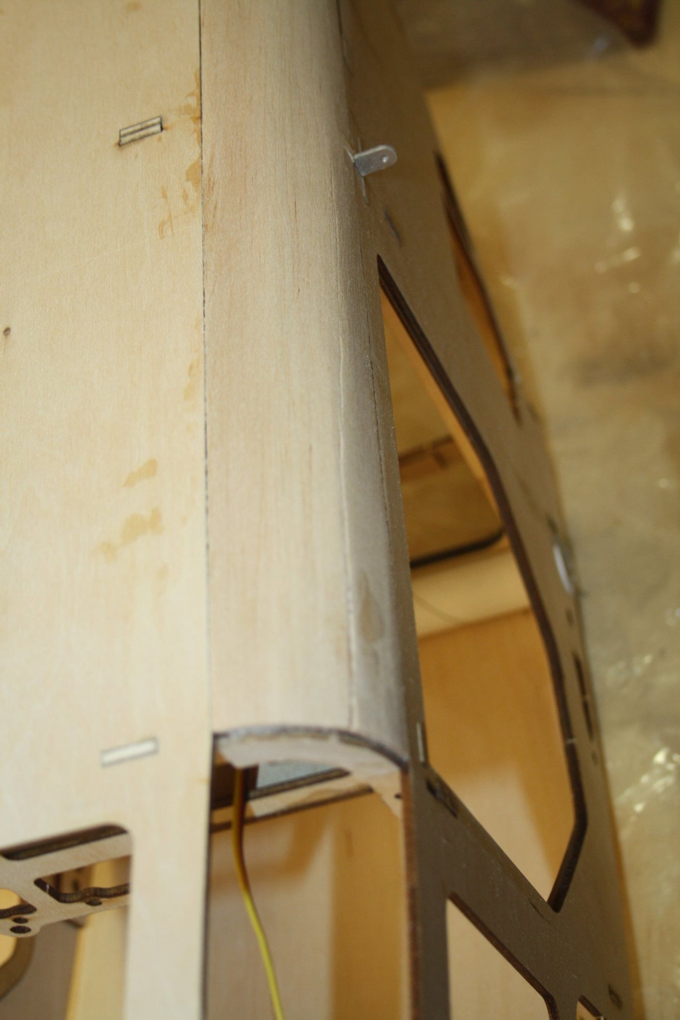
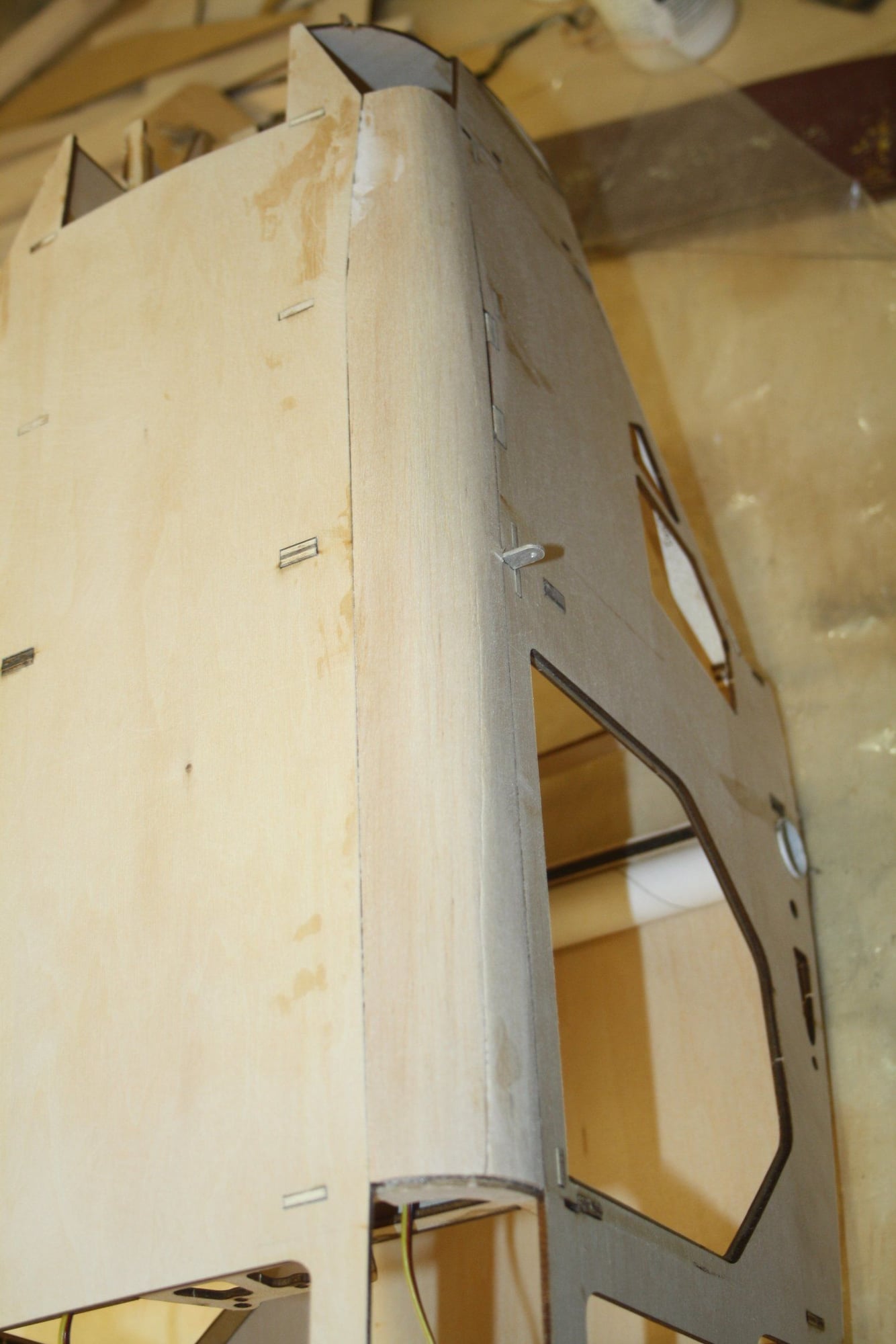
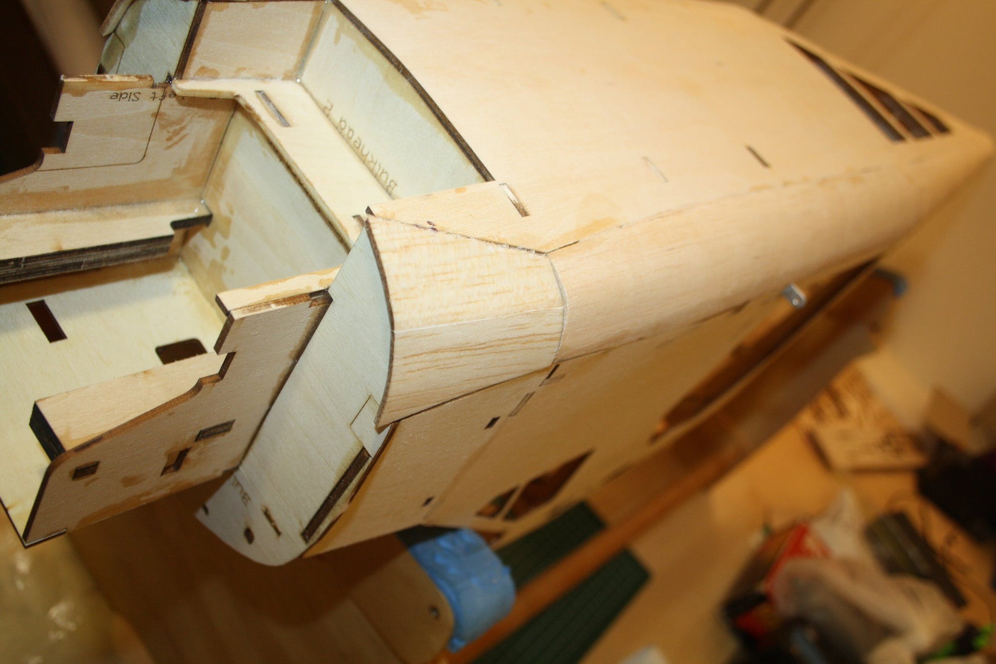
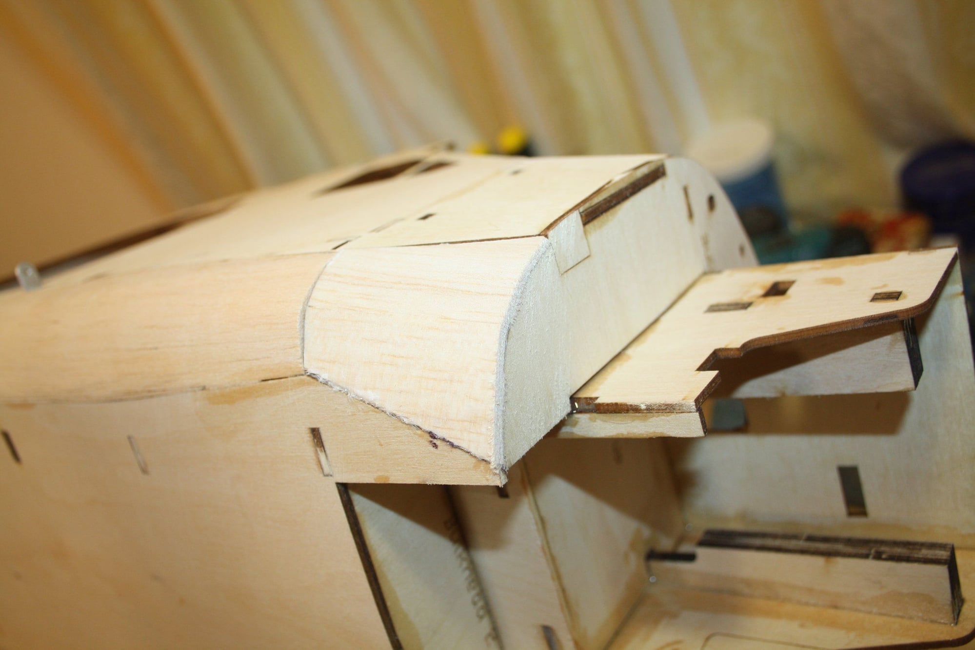
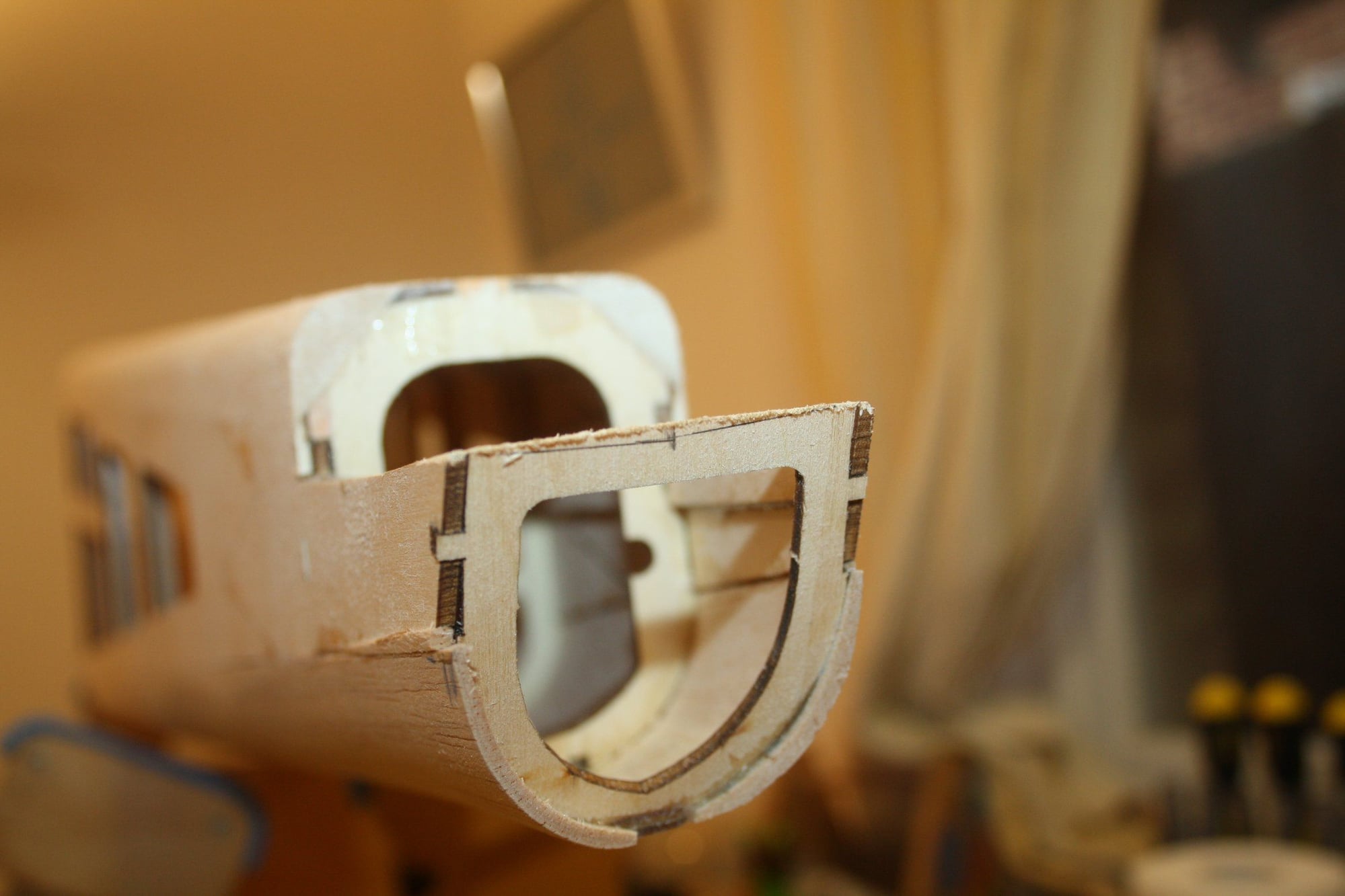
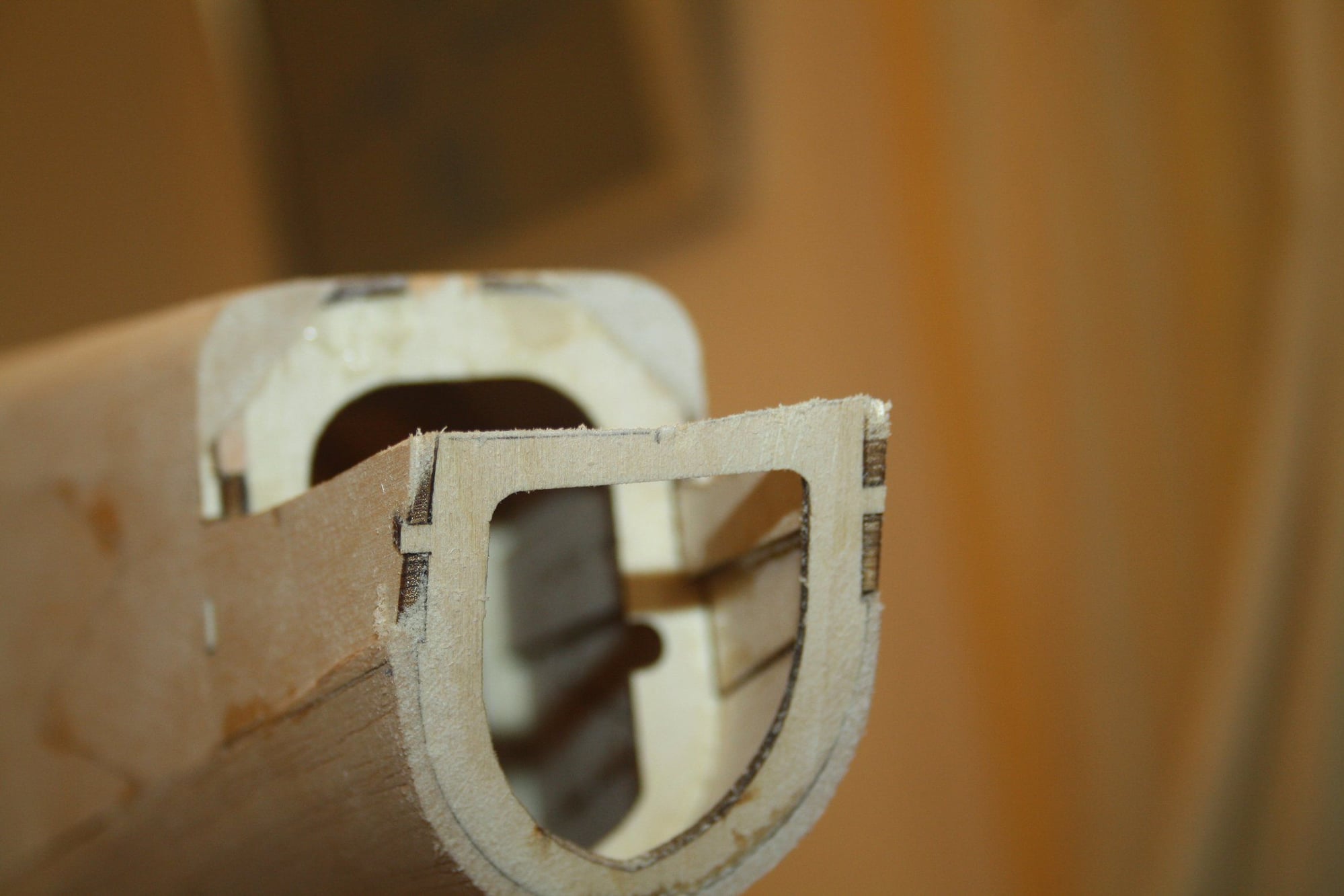
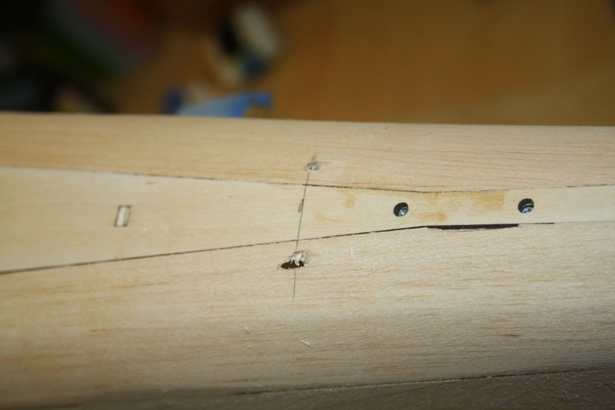
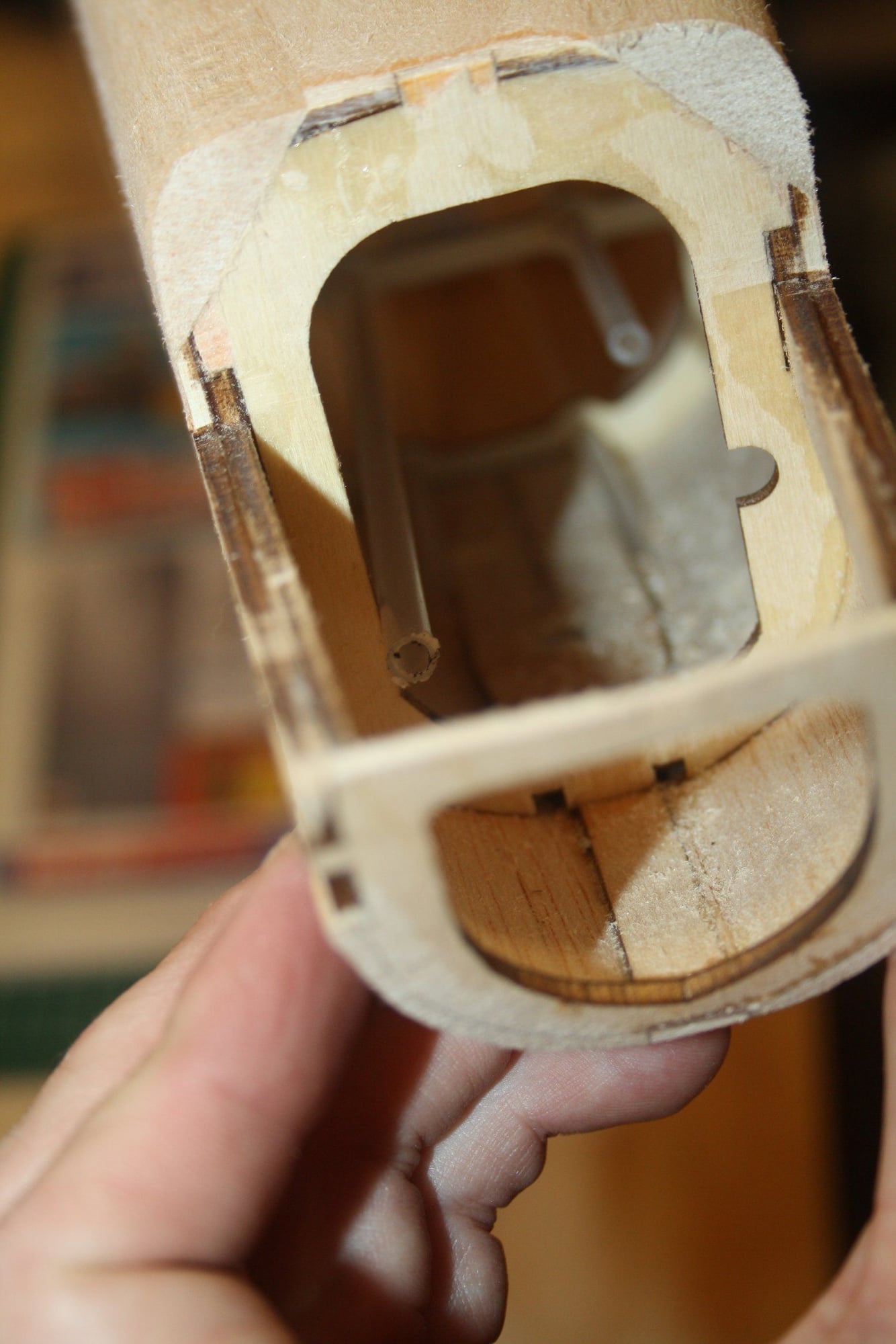
Next was installing the blind nuts for the tail wheel. Then, in keeping on with the failed construction methods and poor material selection of this kit, the photos illustrate the result of trying to follow the instructions for the curved fuselage section (cracked balsa).
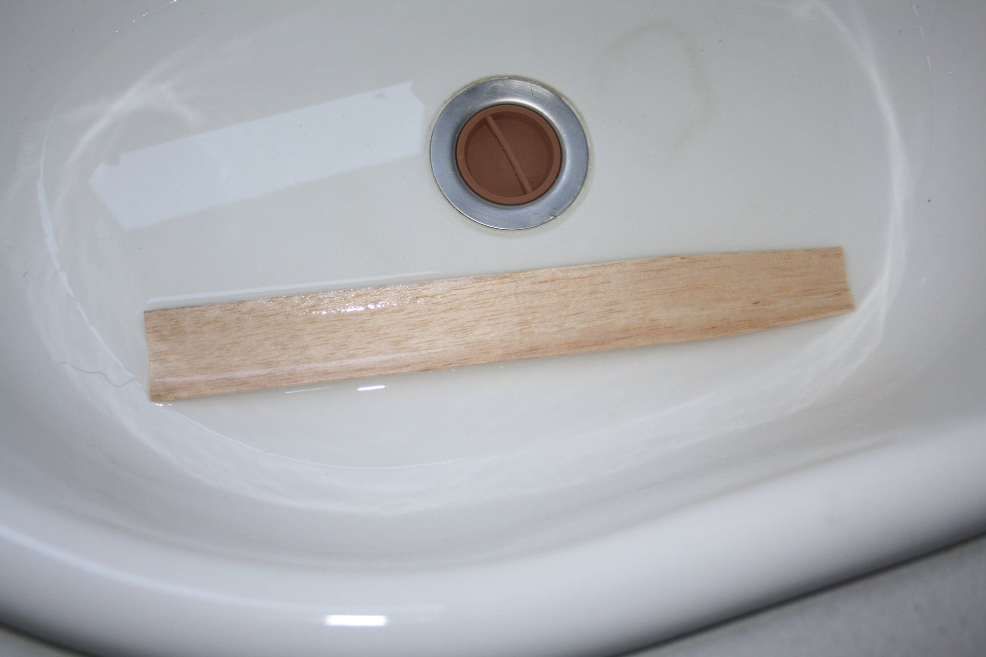
The balsa supplied in the kit was too tough to be bent. I would suggest to wet the parts thoroughly and tape them in position first, and once dry, to glue them in place. It was also reasonably challenging to trim these pieces to fit, but easily resolved with insertion of small pieces in the gaps. I finished the process with micro-balloons.

Cheers,
Eran
The balsa supplied in the kit was too tough to be bent. I would suggest to wet the parts thoroughly and tape them in position first, and once dry, to glue them in place. It was also reasonably challenging to trim these pieces to fit, but easily resolved with insertion of small pieces in the gaps. I finished the process with micro-balloons.
Cheers,
Eran


 11-18-2022, 08:46 PM
#66
Thread Starter
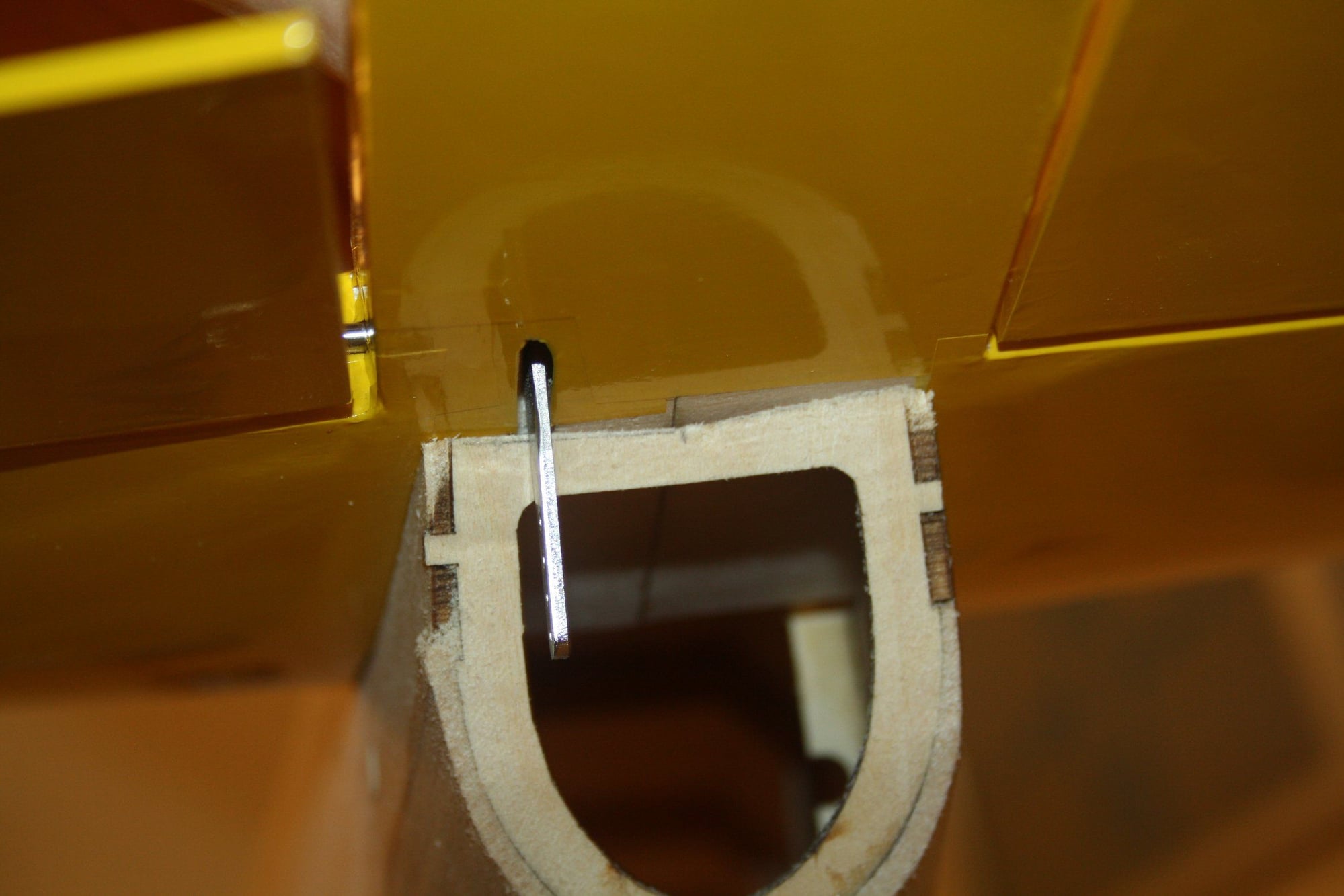
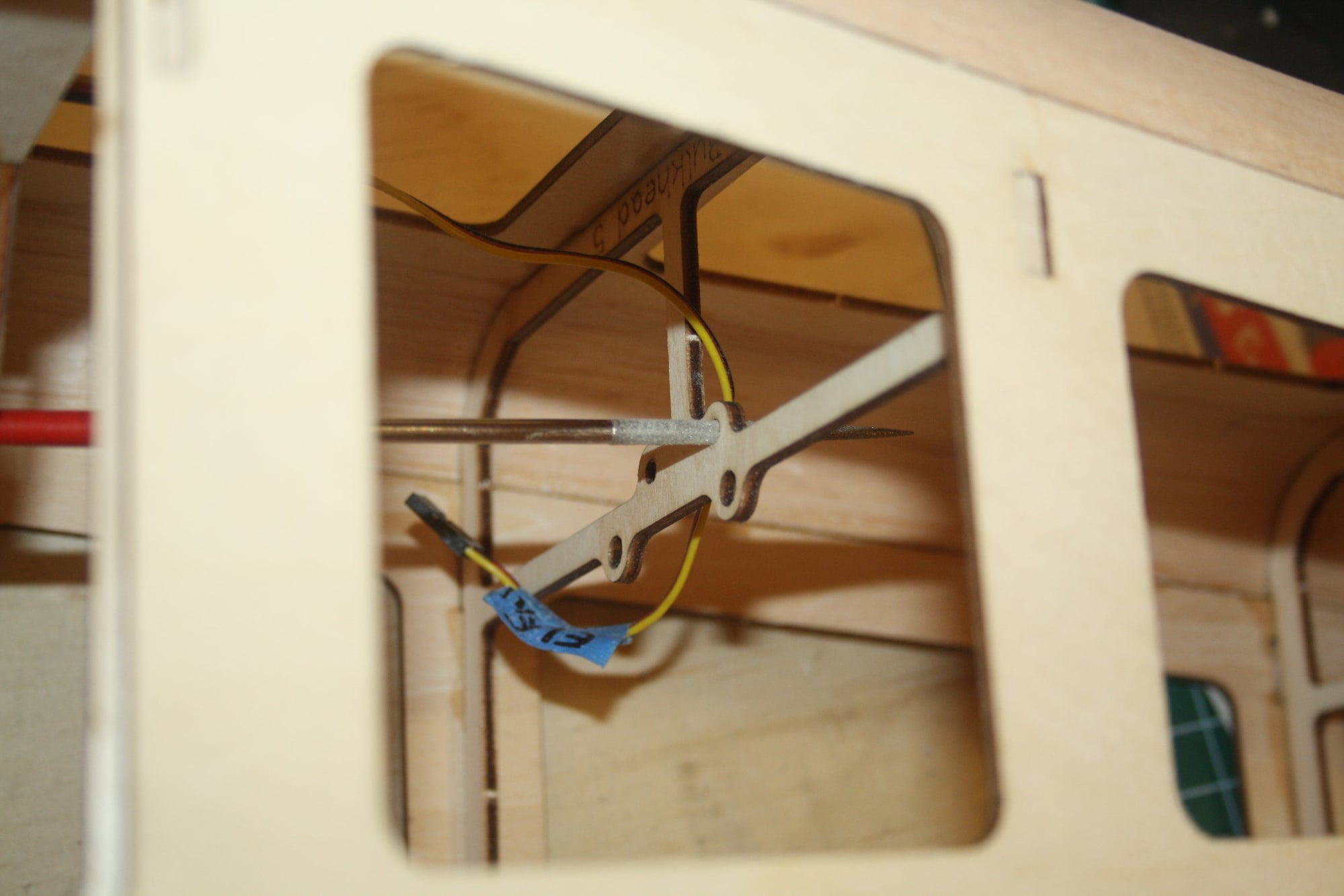
The tail former required some trimming to have the stabiliser actually sitting in position properly. Another obvious issue was the restriction of the control horn movement.
11-18-2022, 08:49 PM
#67
Thread Starter
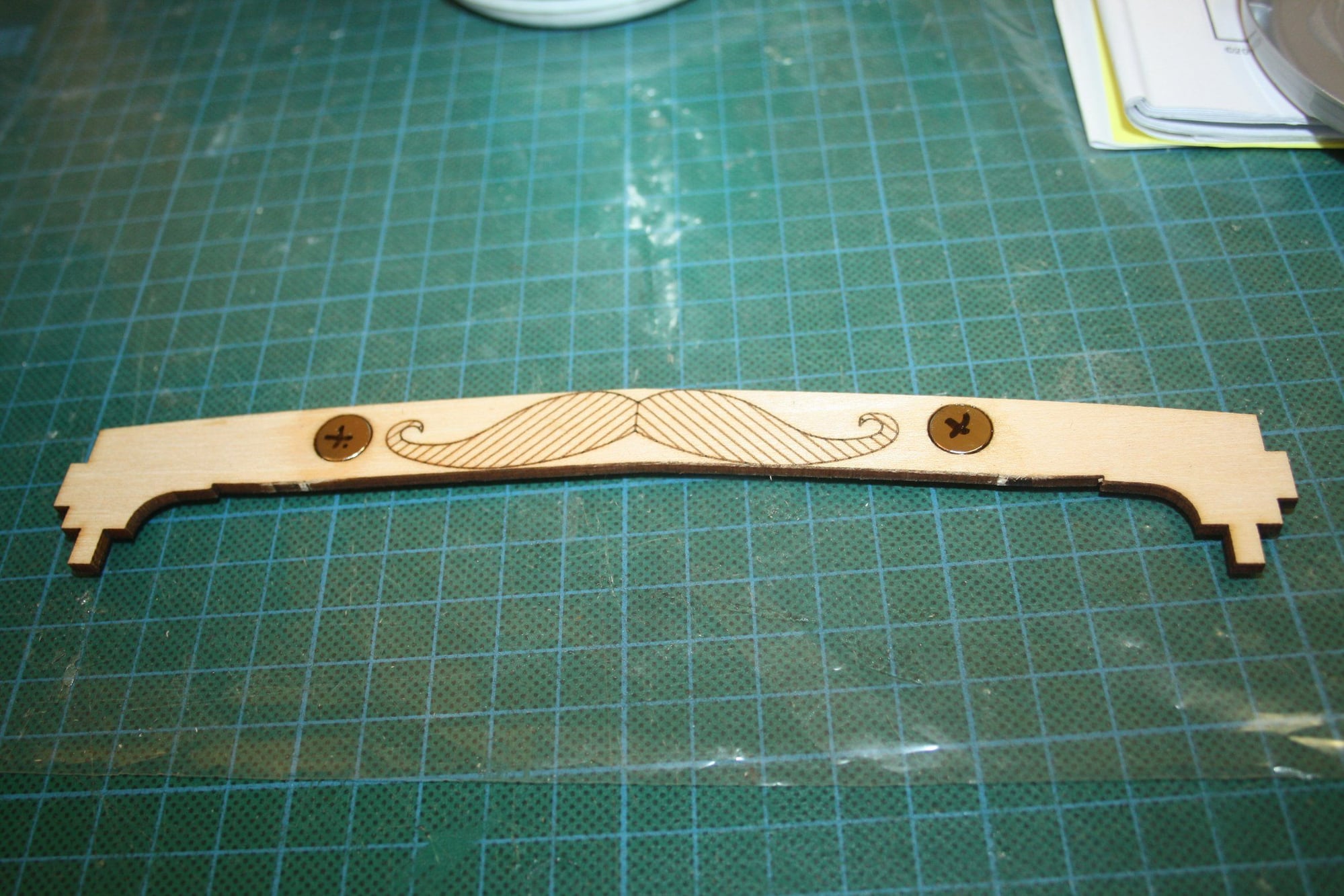
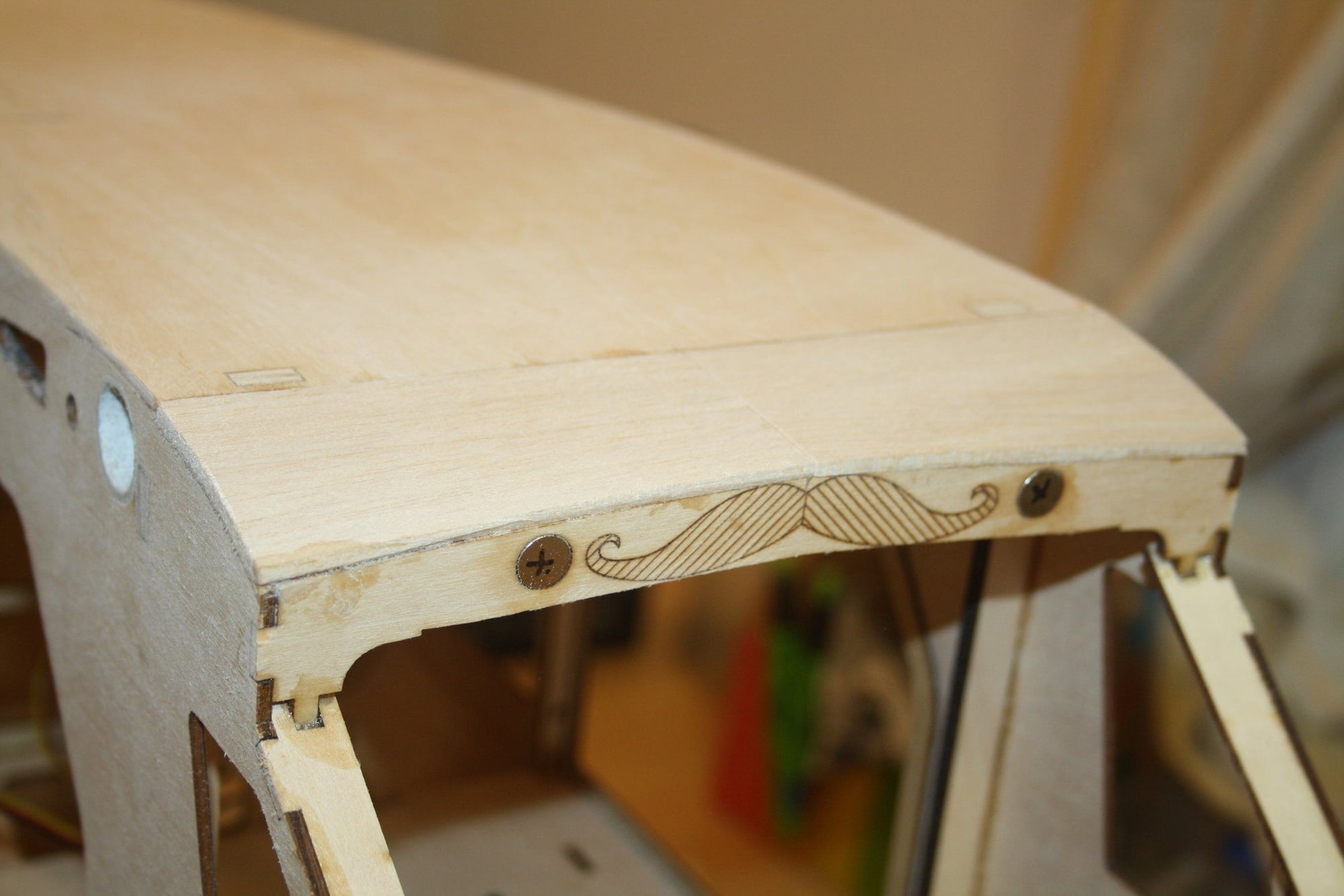
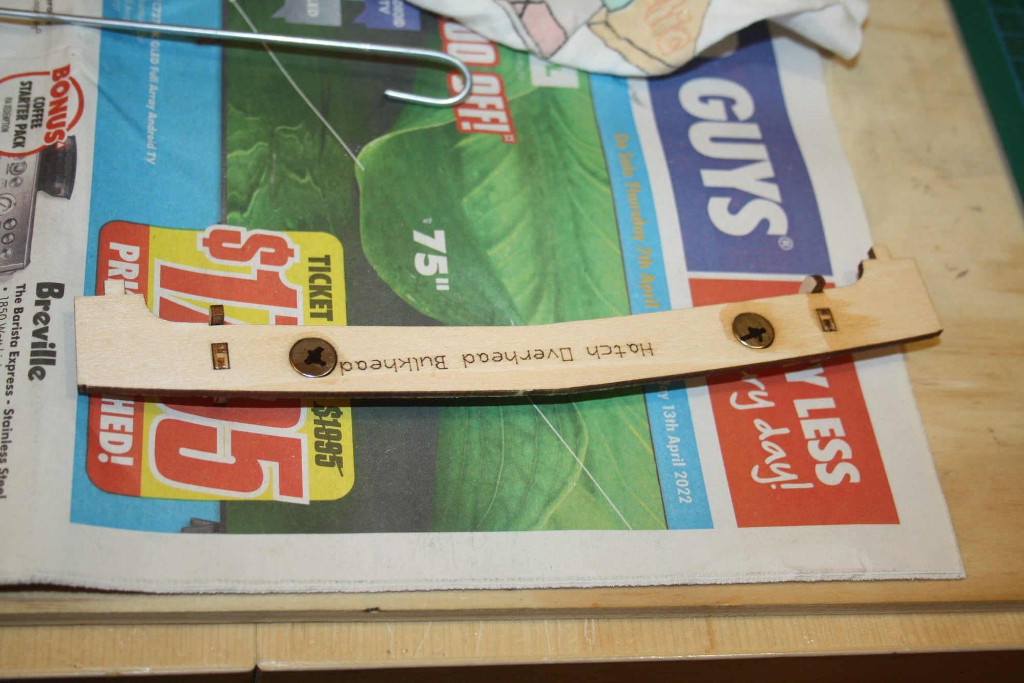
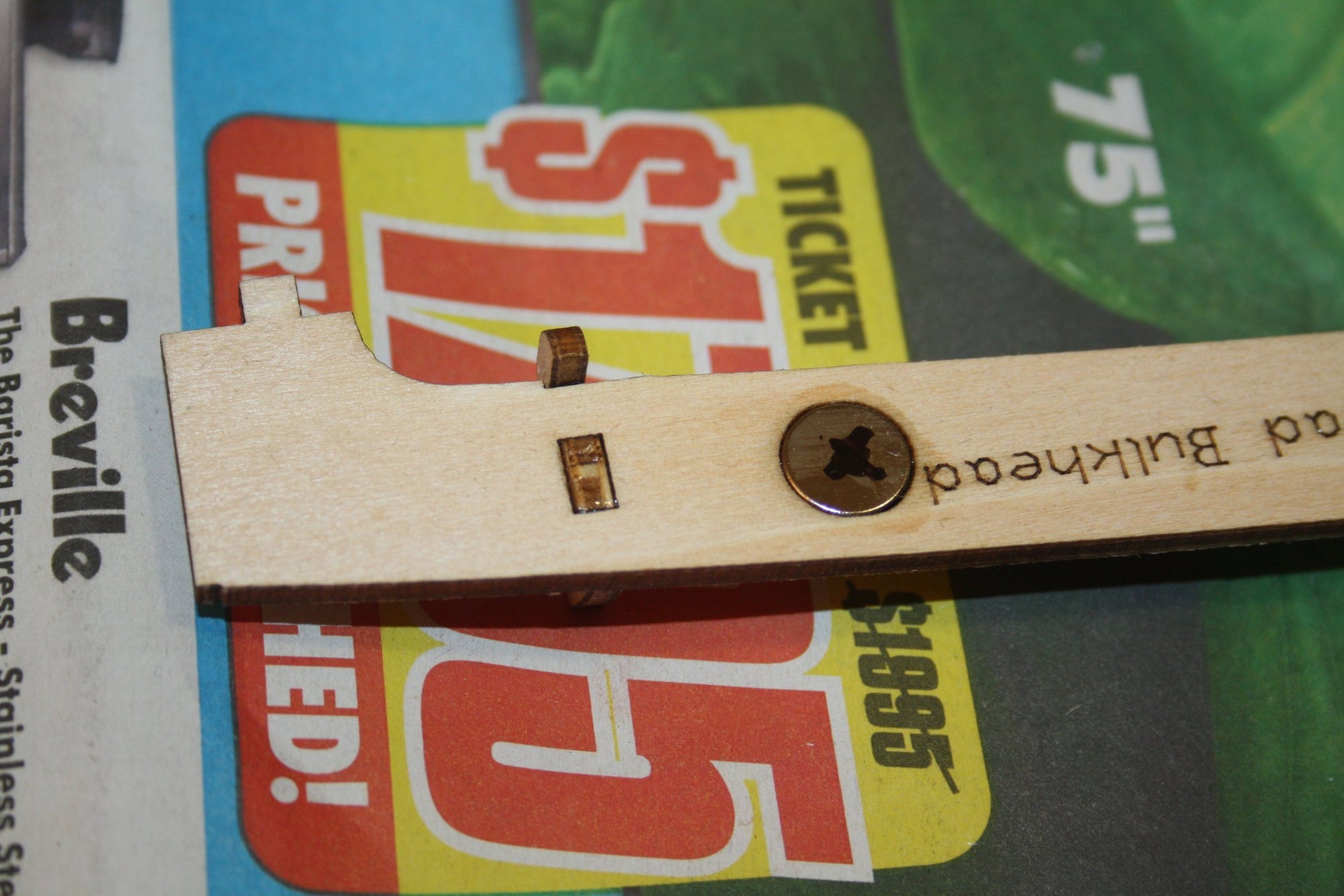
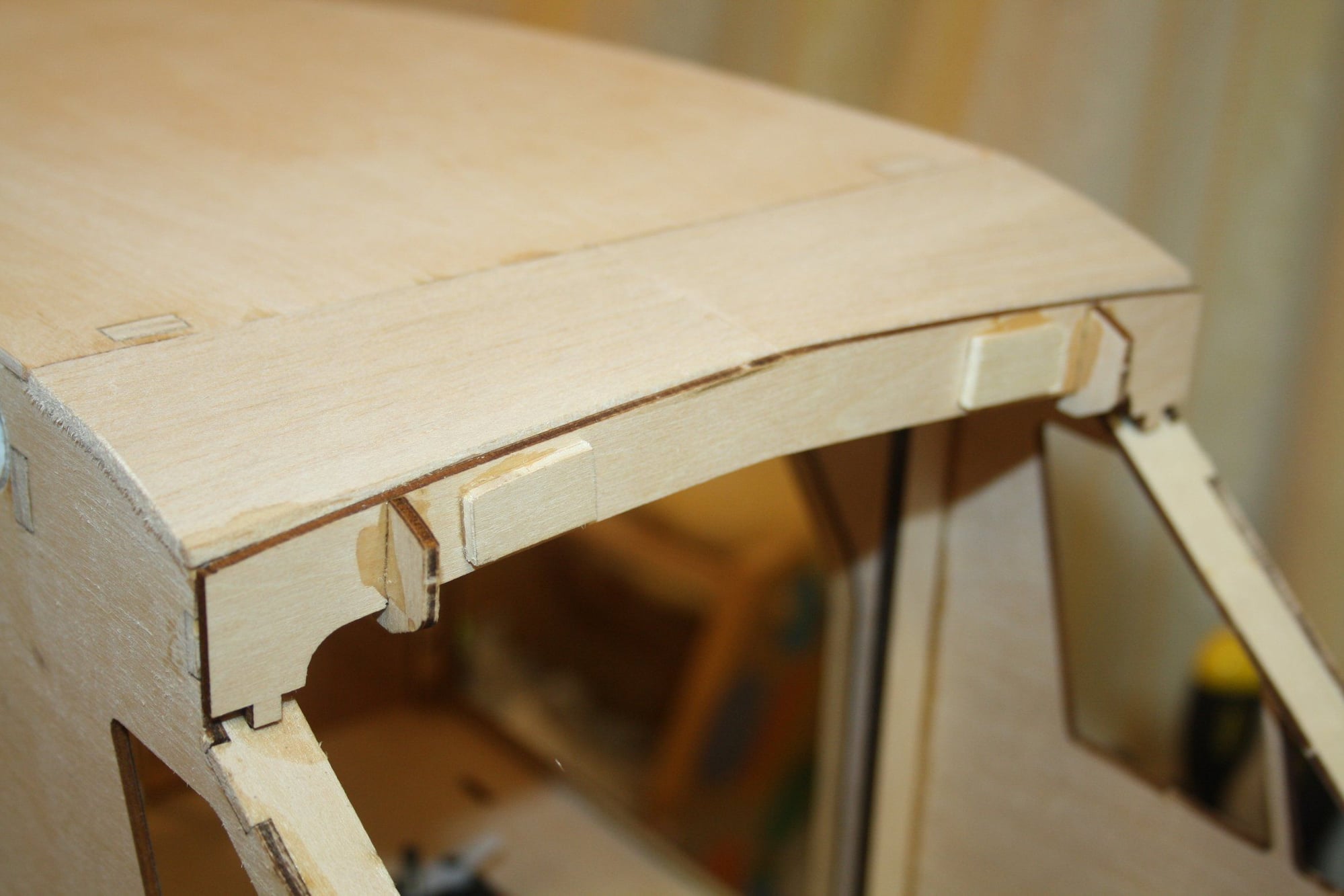
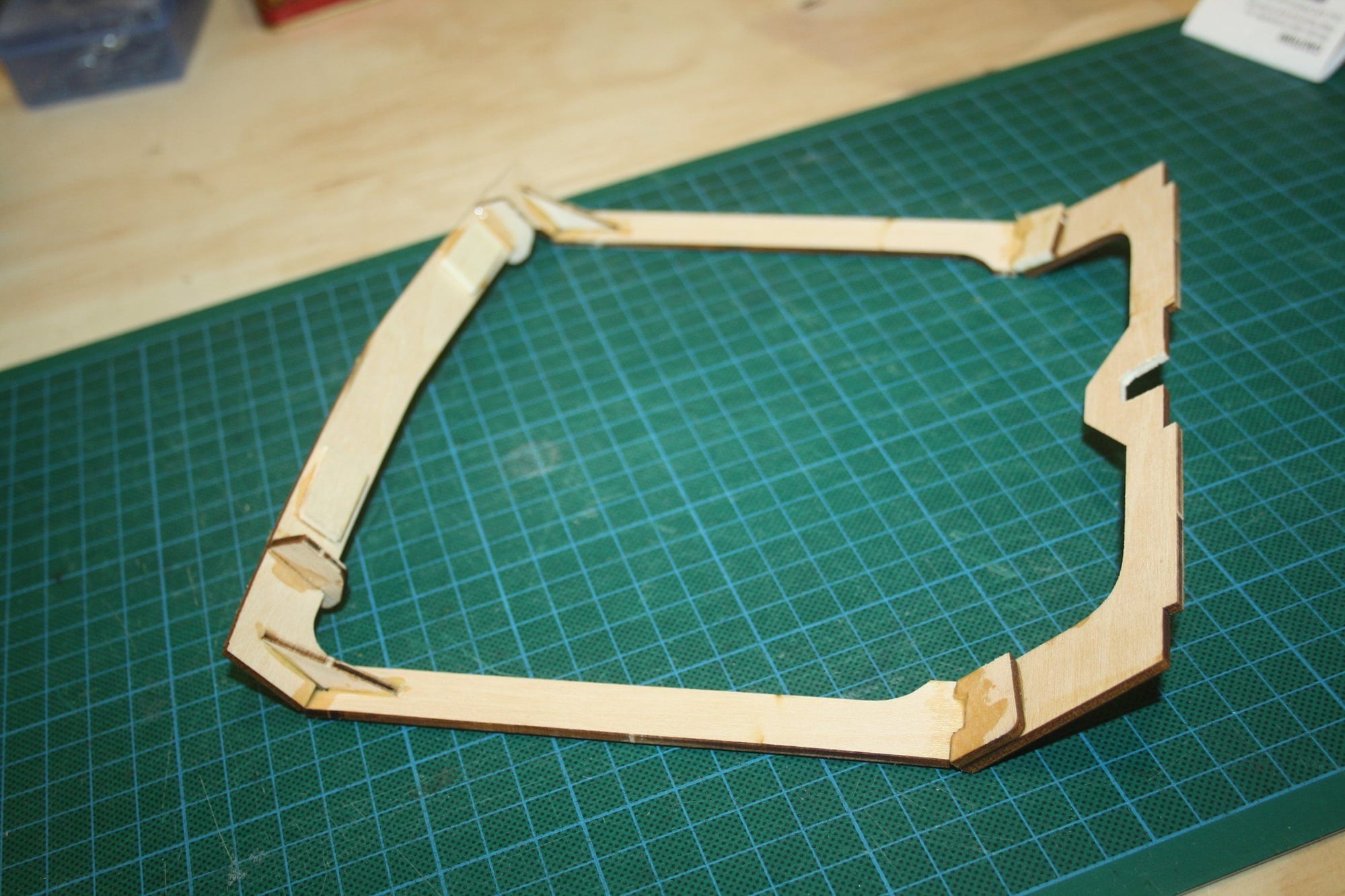
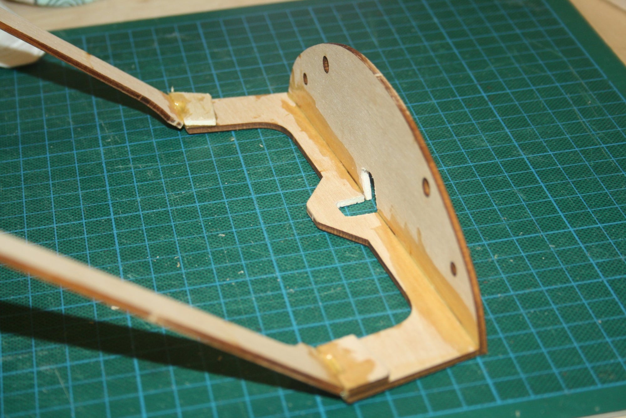
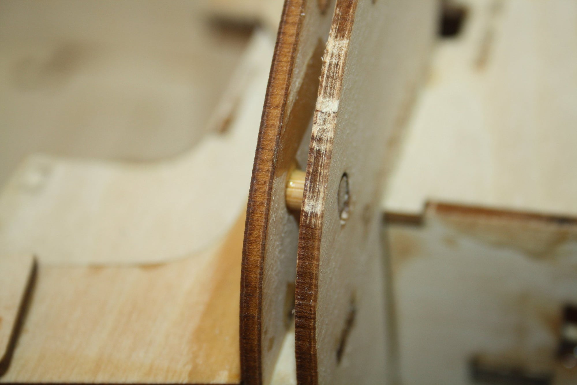
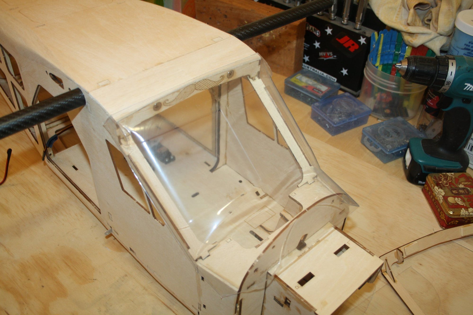
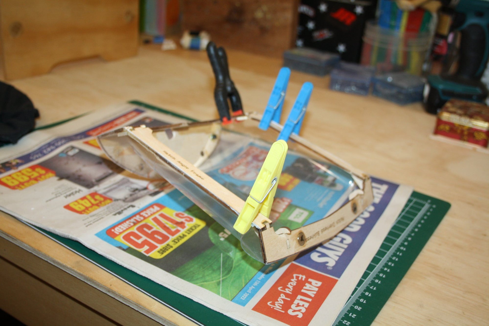
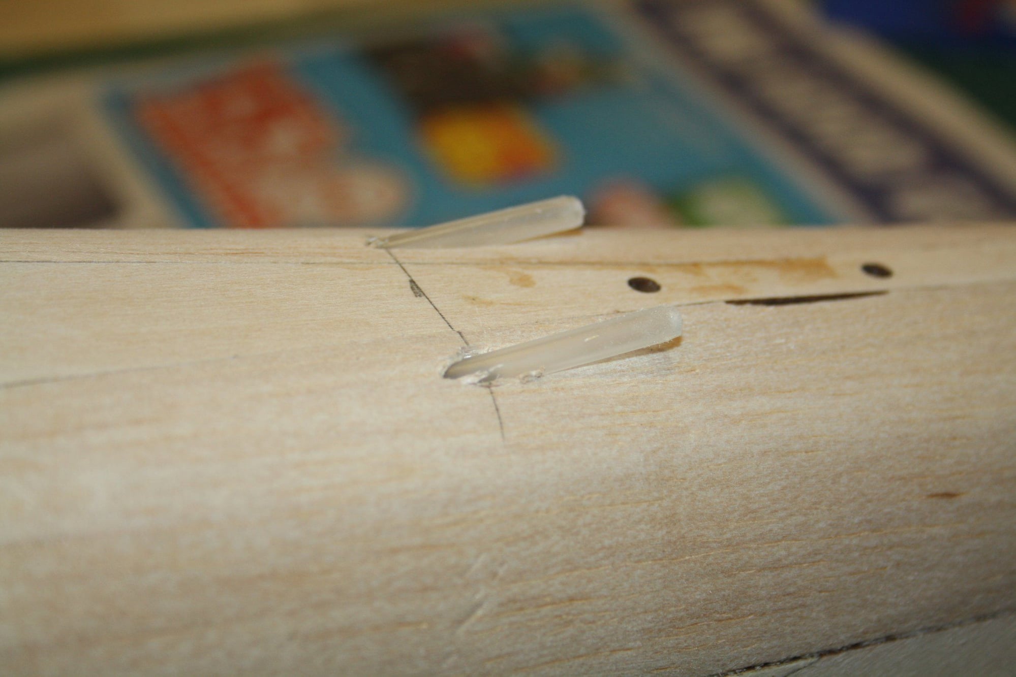
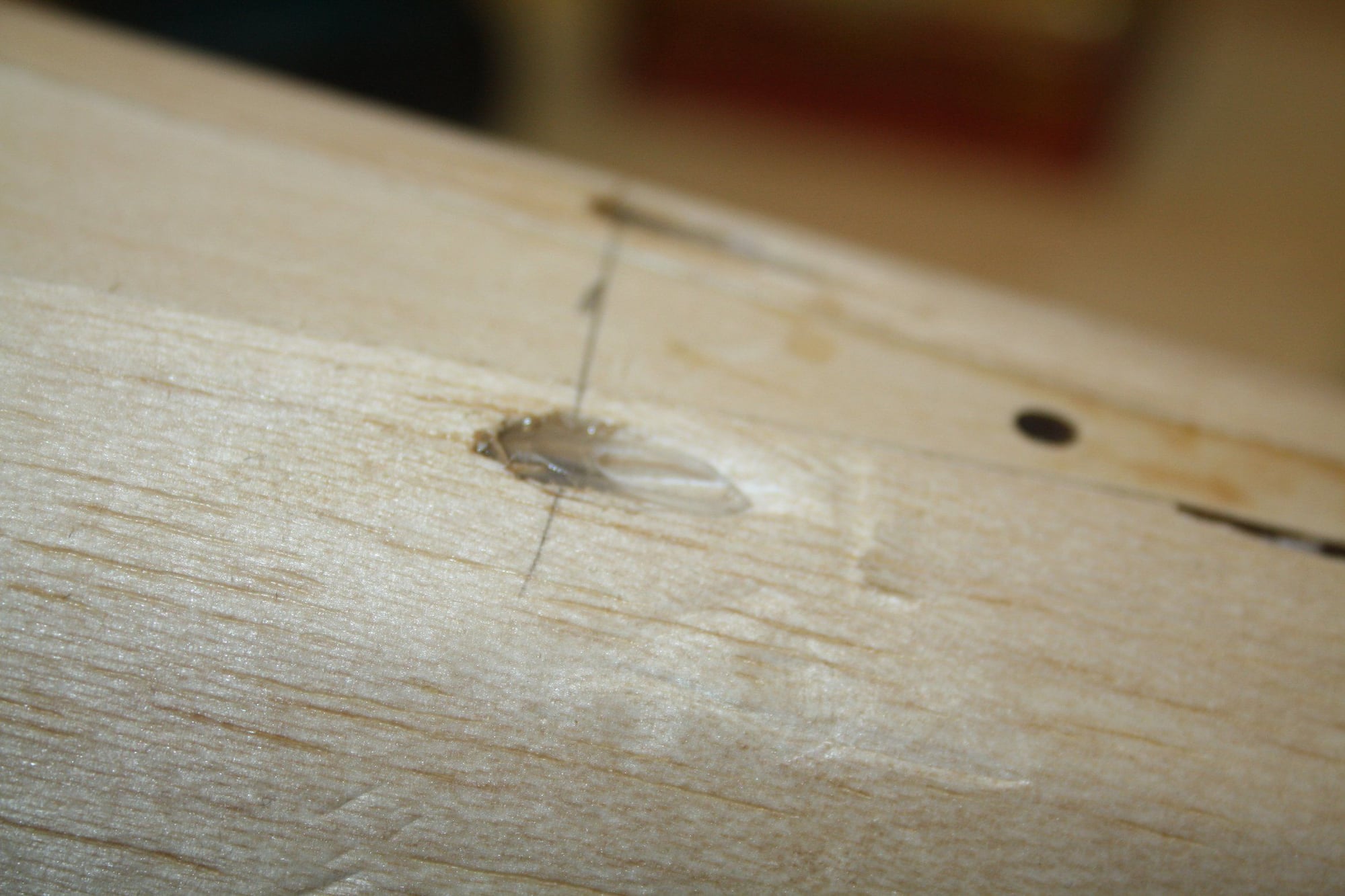
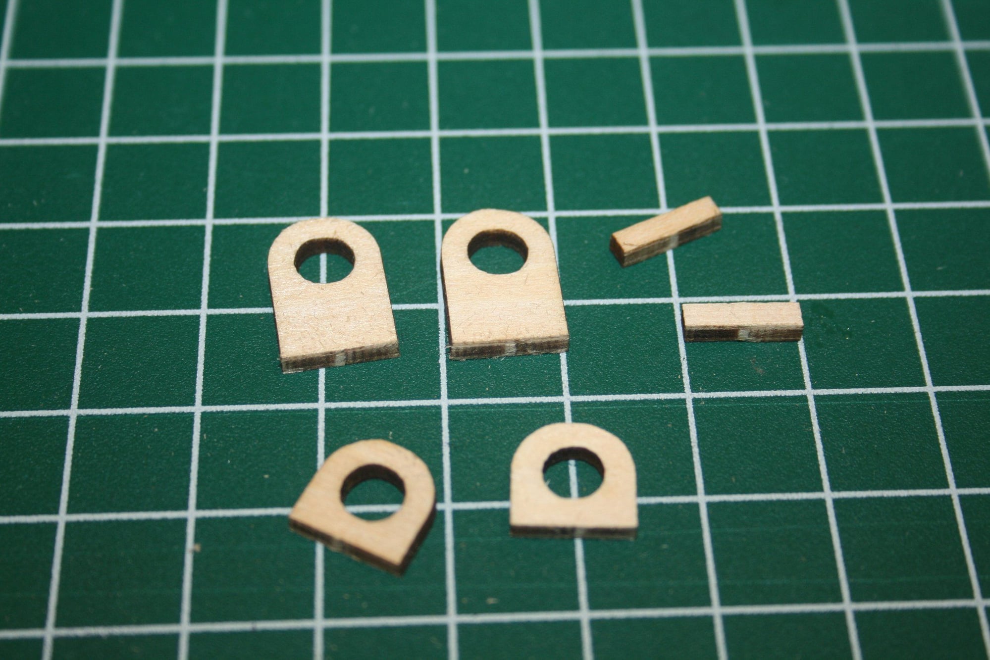
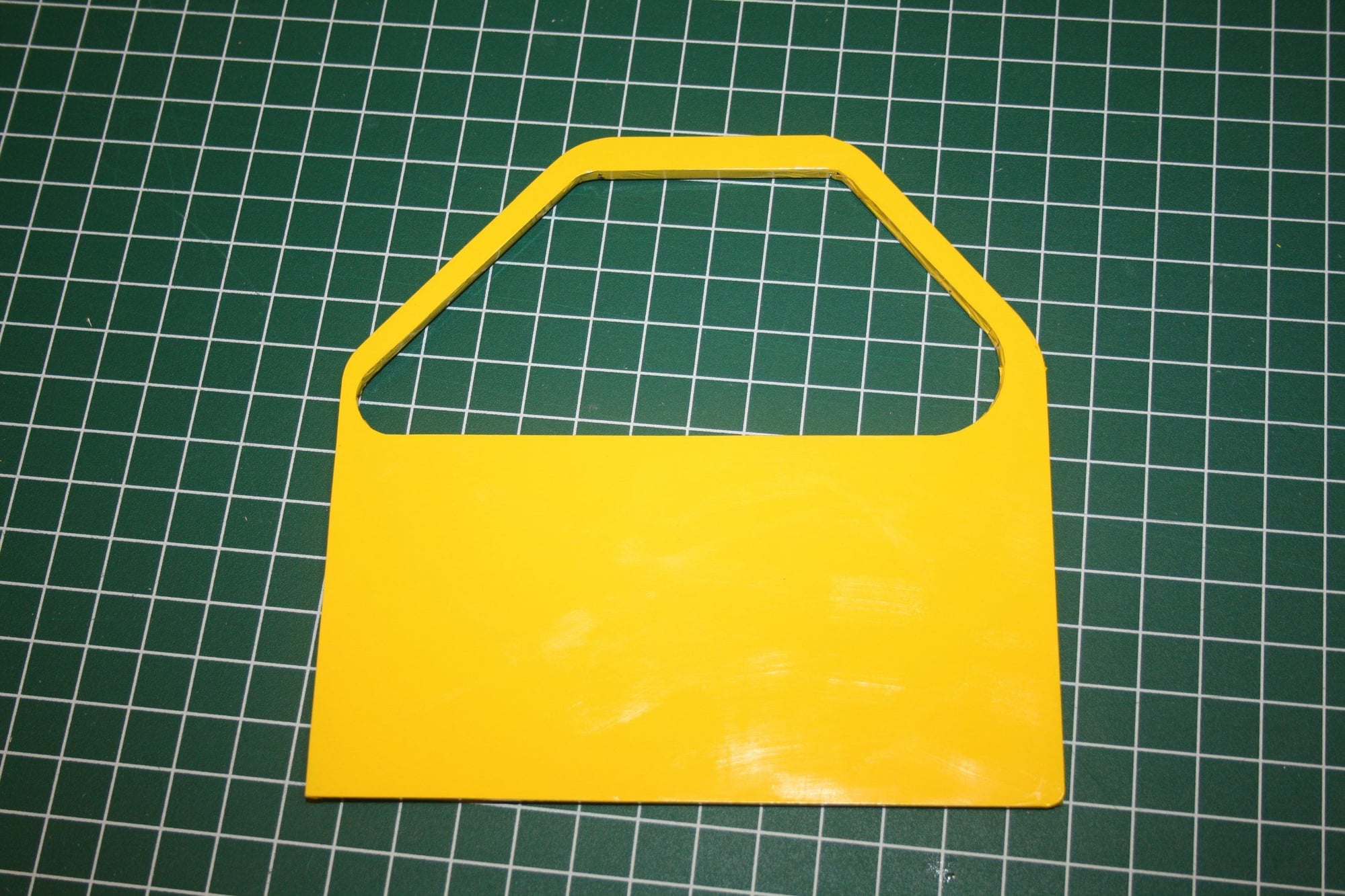
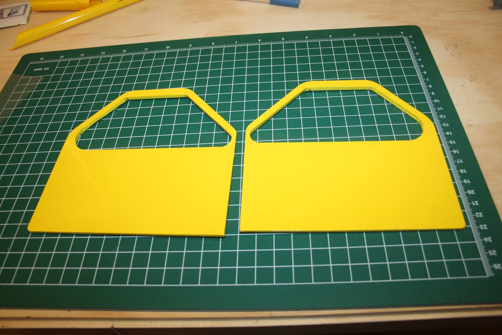
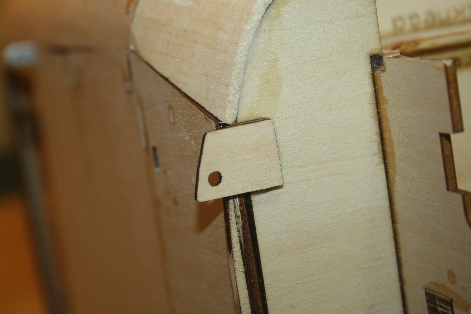
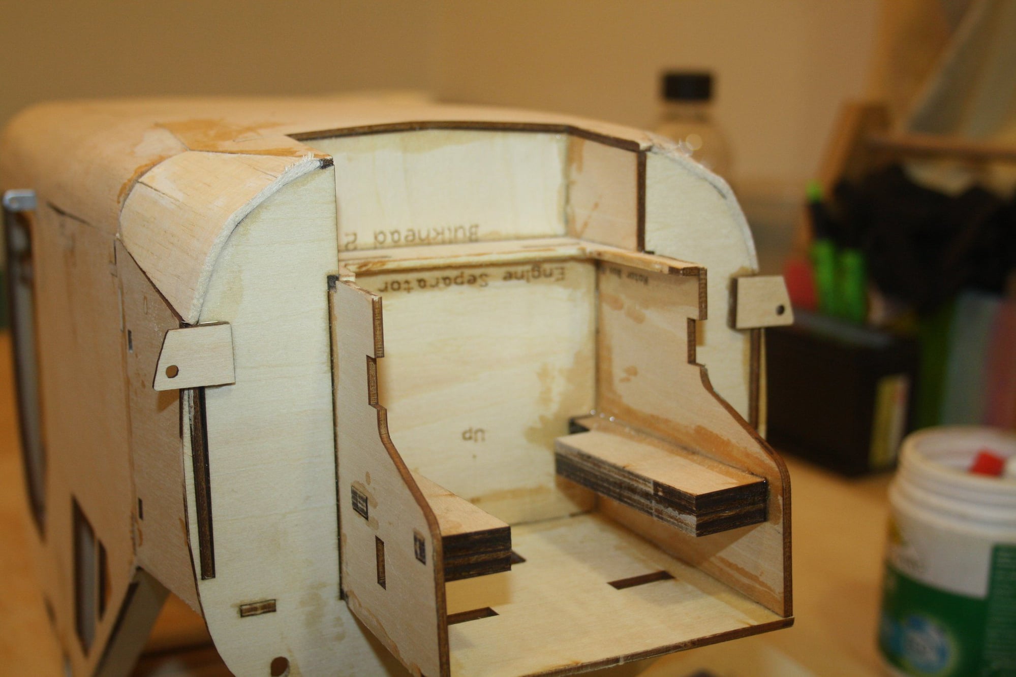
Framing of the front window hatch and setting up the magnets. As becoming the norm with this kit, the parts don't fit properly and require me to make some pieces to maintain the frame integrity.

Cheers,
Eran
Cheers,
Eran
11-18-2022, 08:55 PM
#68
Thread Starter
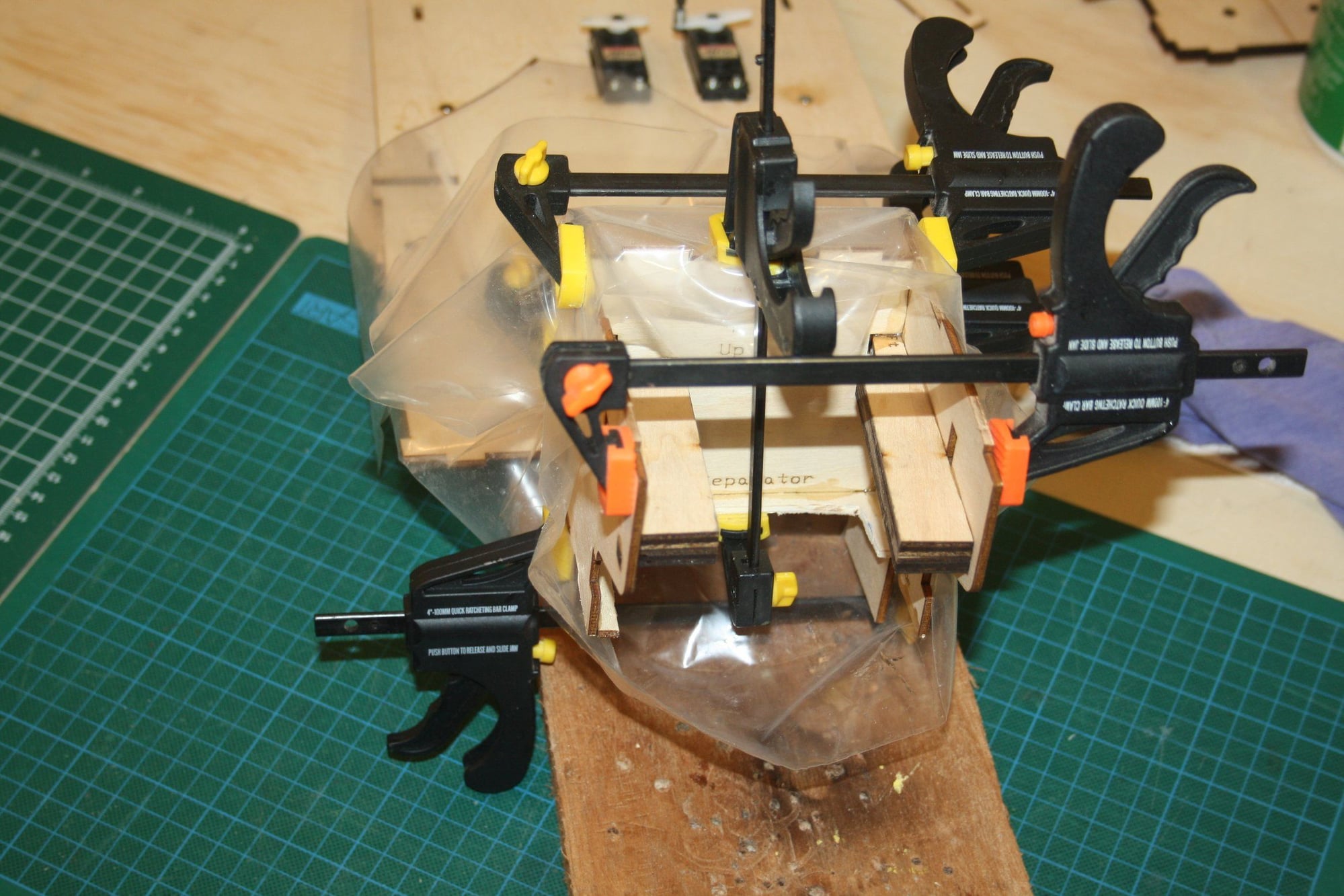
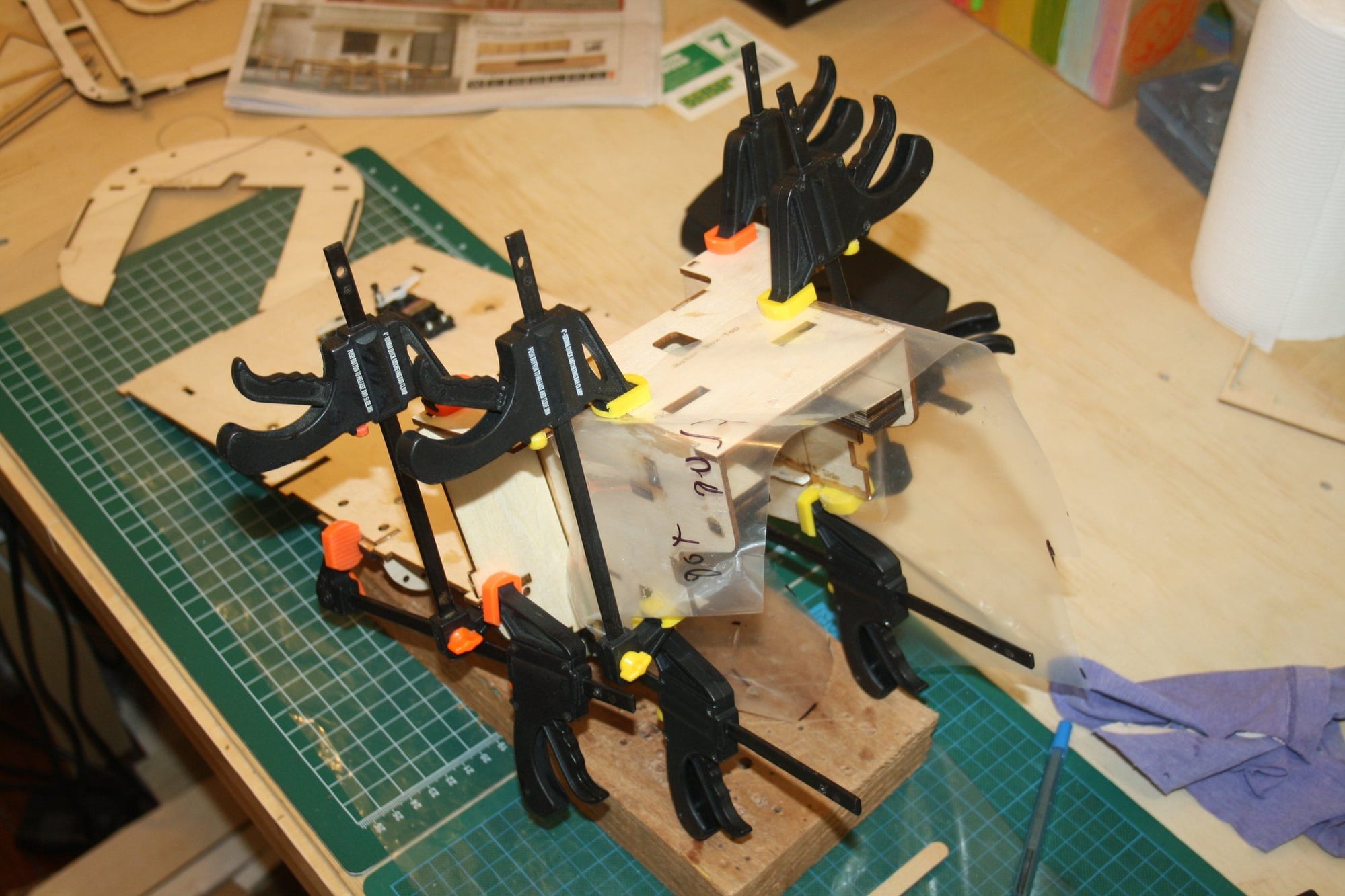
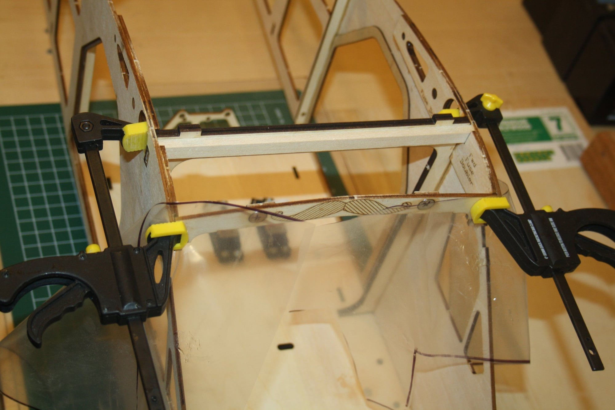
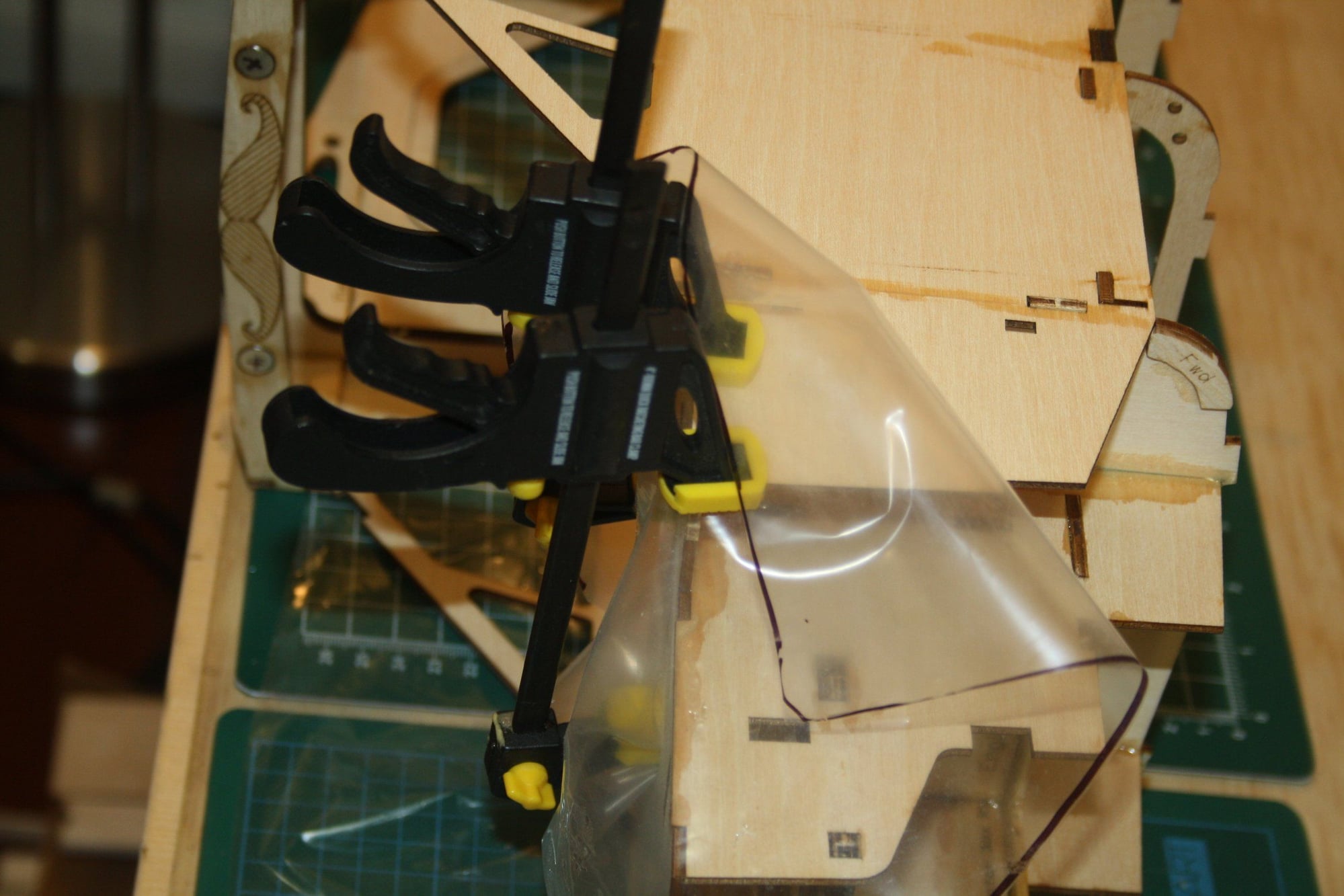
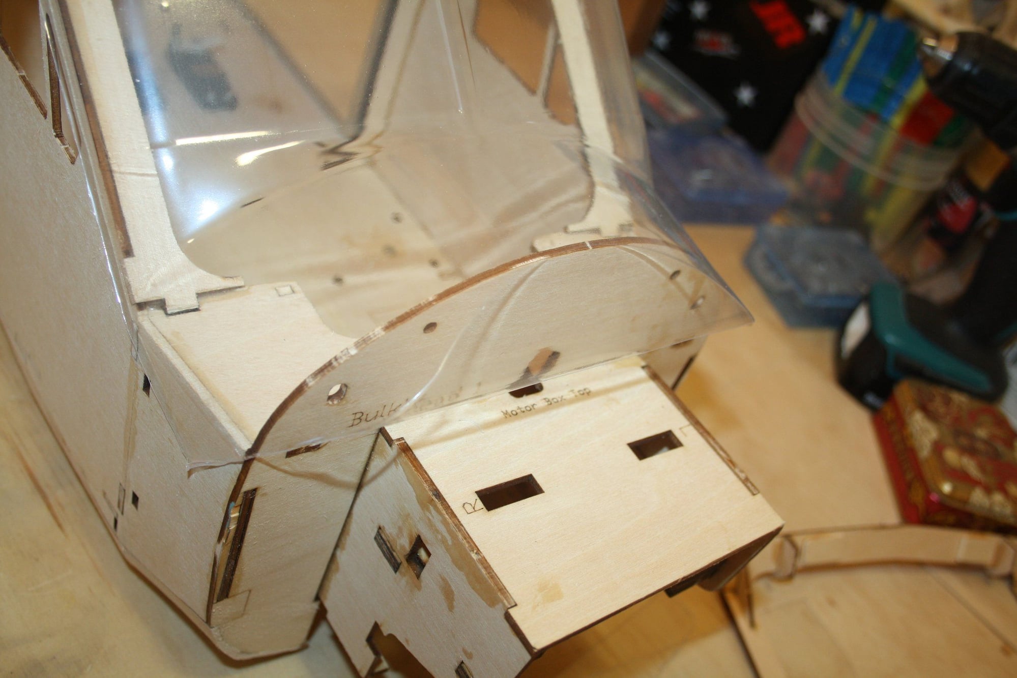
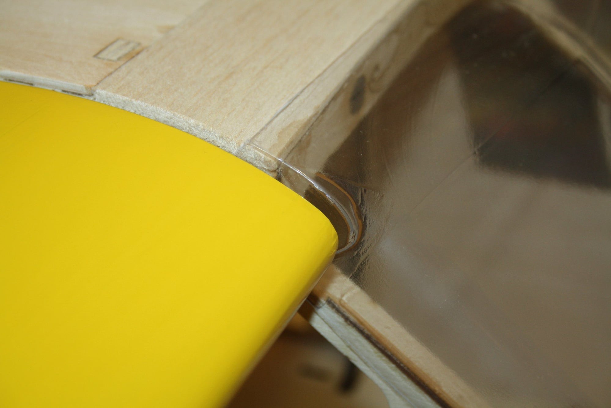
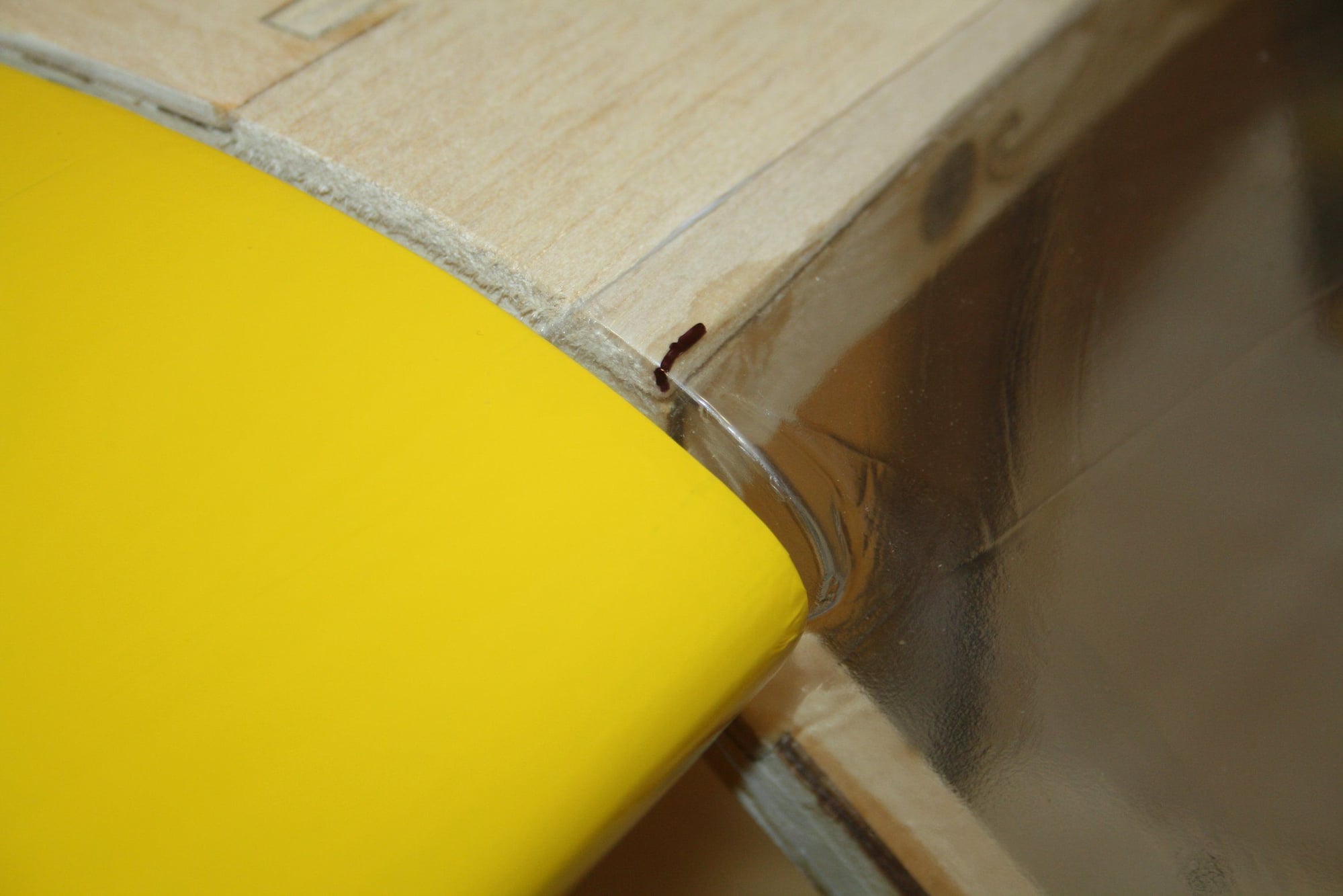
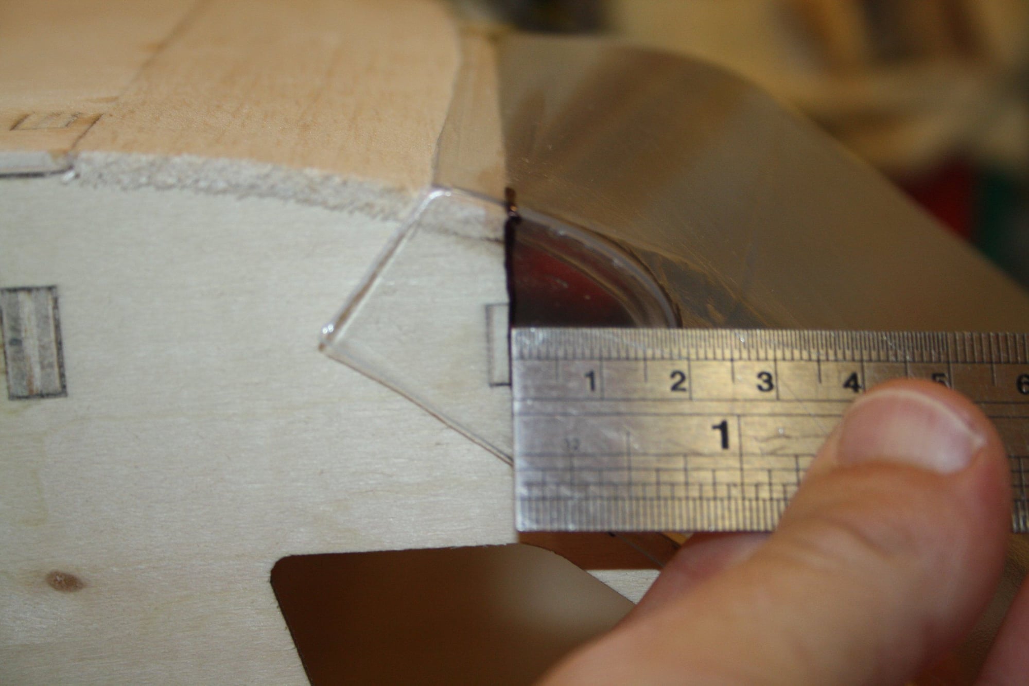
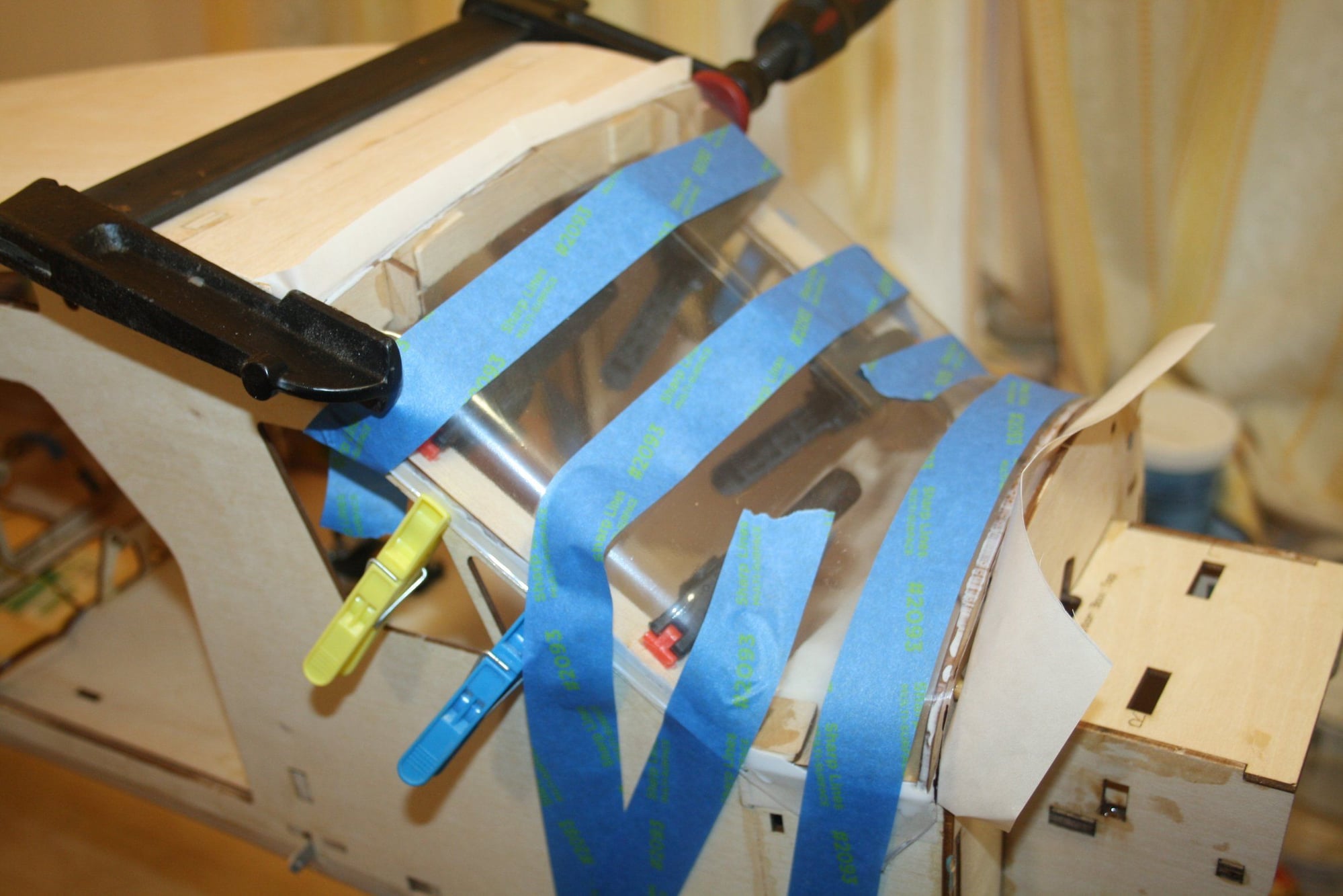
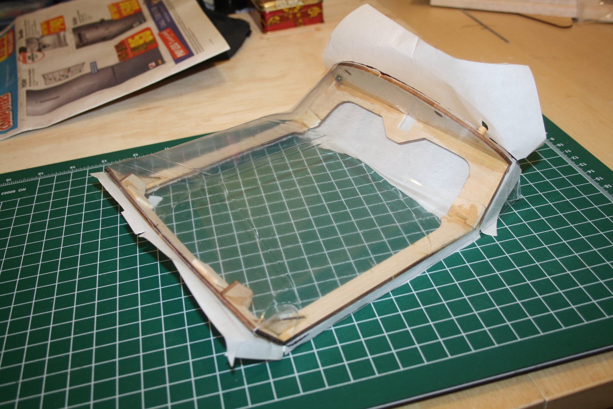
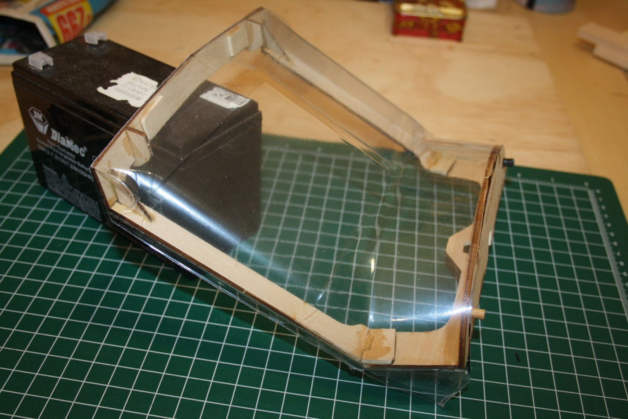
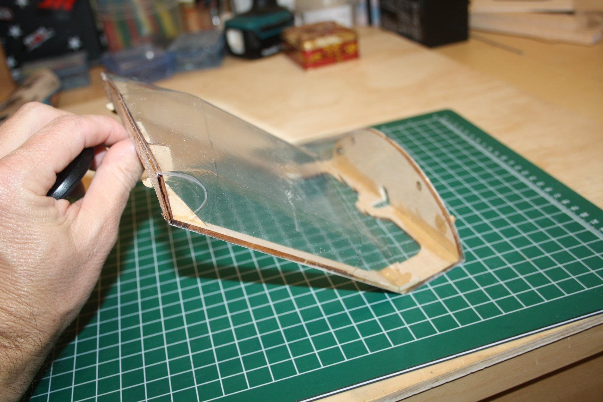
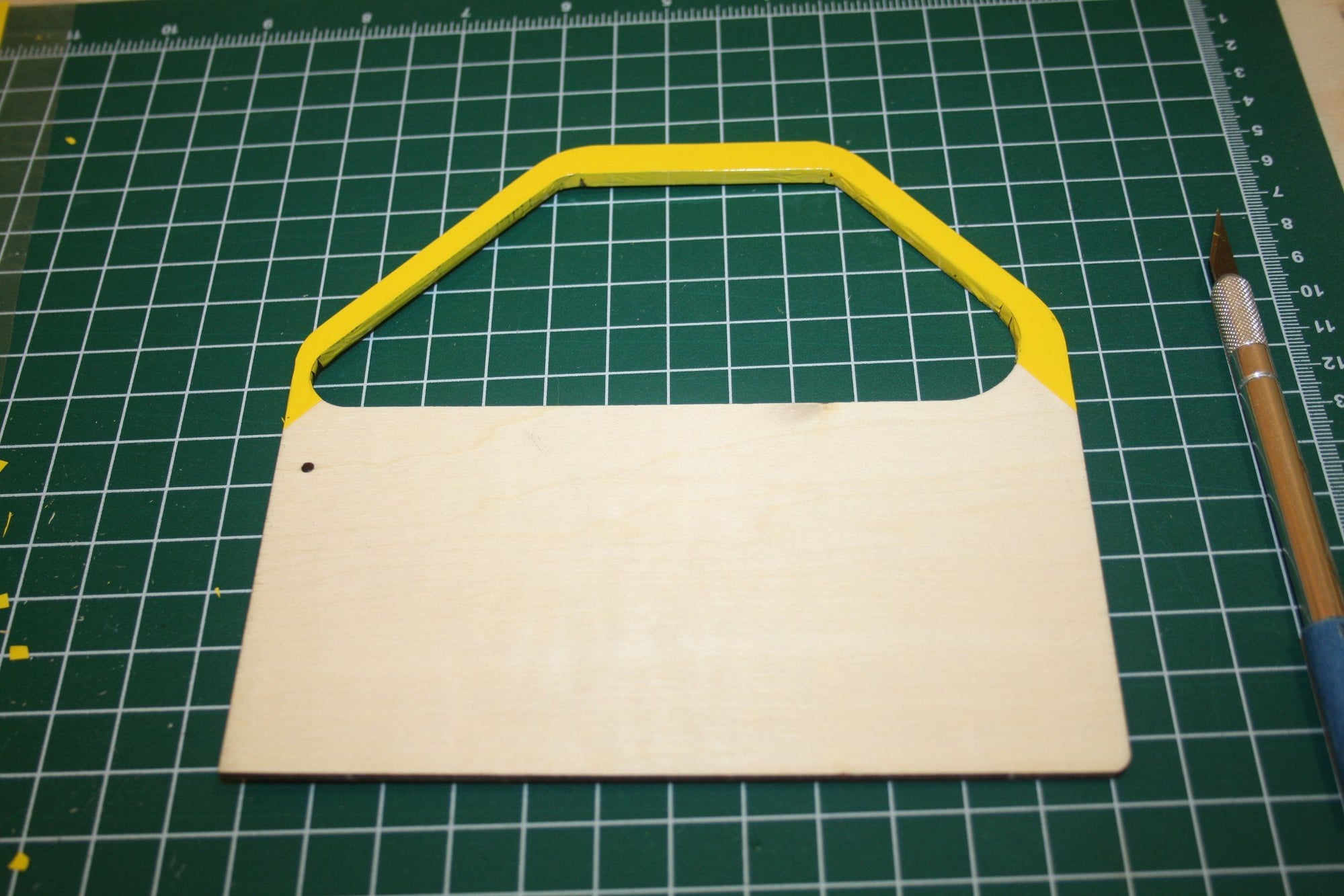
Some careful measuring and marking prior to cutting the access material, and then gluing the clear plastic to the frame. The quality of the engineering and molding of the clear plastic parts I used from the kit is surprisingly good. Note the non-stick paper used between the window frame and the rest of the fuselage while the glue dries. Formula 560 canopy glue was used.

 .
.
Cheers,
Eran
.Cheers,
Eran
11-18-2022, 09:01 PM
#69
Thread Starter
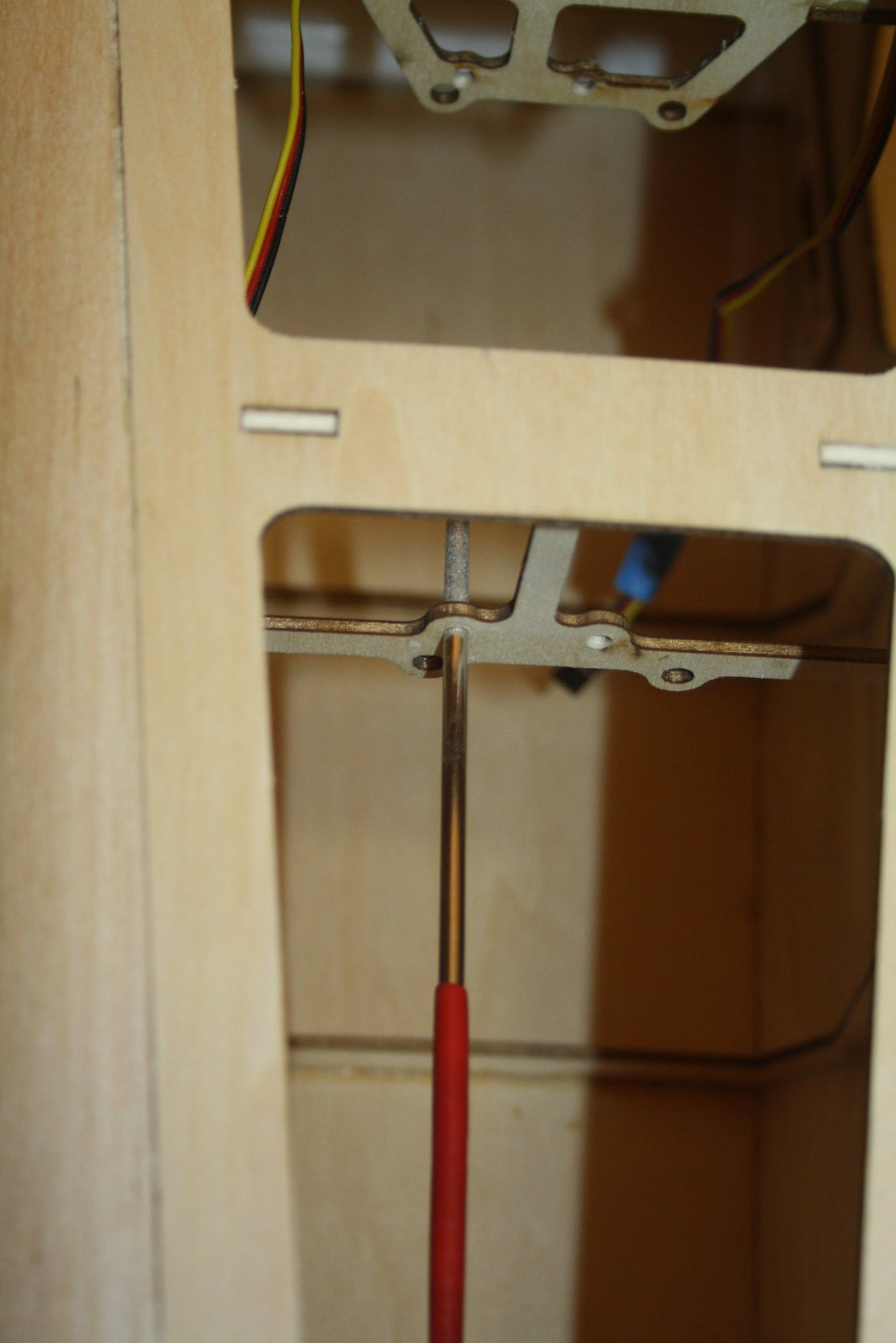
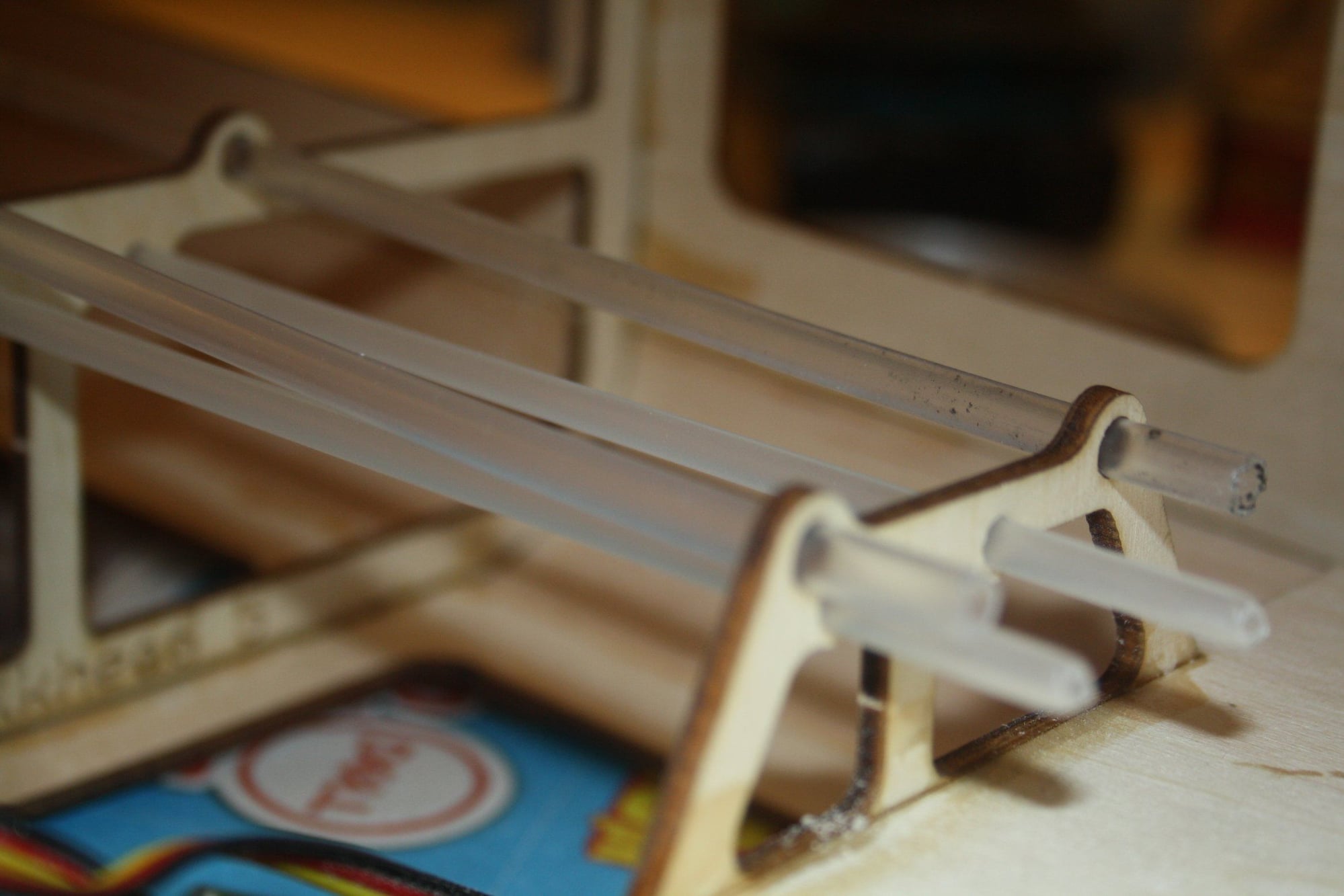
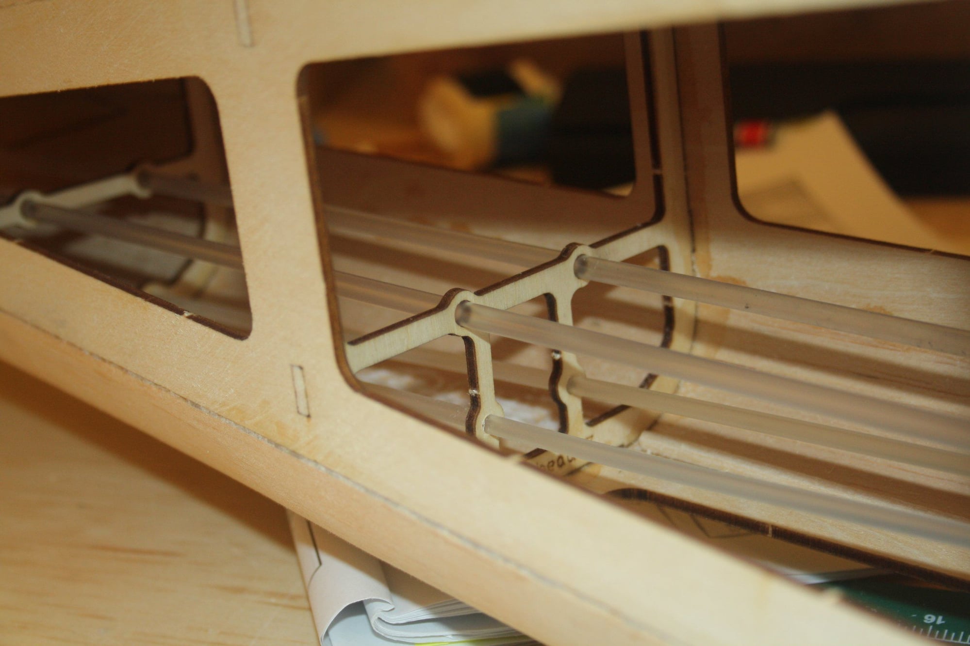
Now, this is where swearing in multiple languages come handy! All the laser cut holes for the control rod sleeves were too small and required to be enlarge individually. With the fuselage fully assembled, this was not an easy task... Another required mentioning the lack of engineering principles understanding by the designer and the fact that this should have been correct at prototyping if one was ever done.
Cheers,
Eran
Cheers,
Eran
 11-28-2022, 04:33 AM
#71
Thread Starter
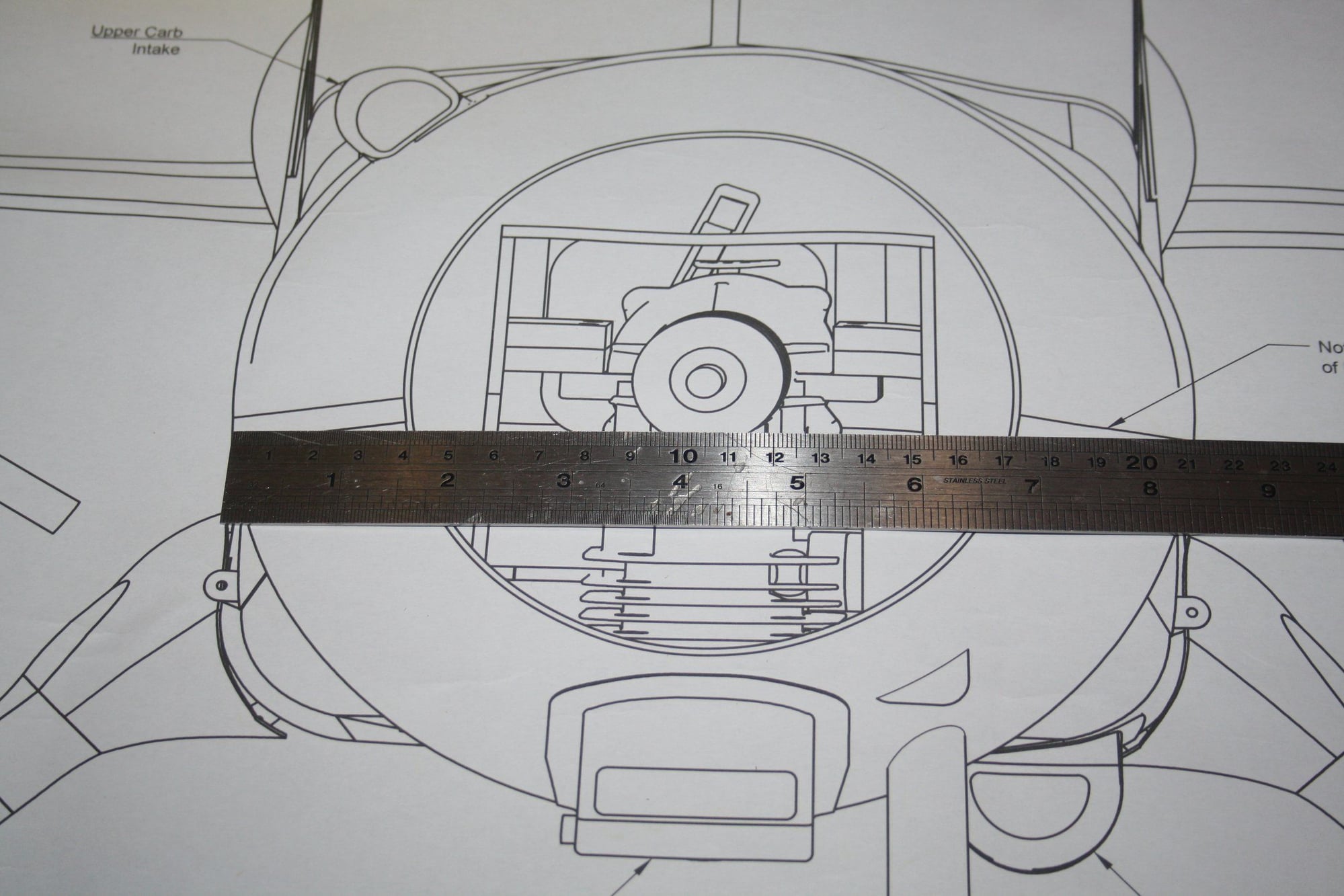
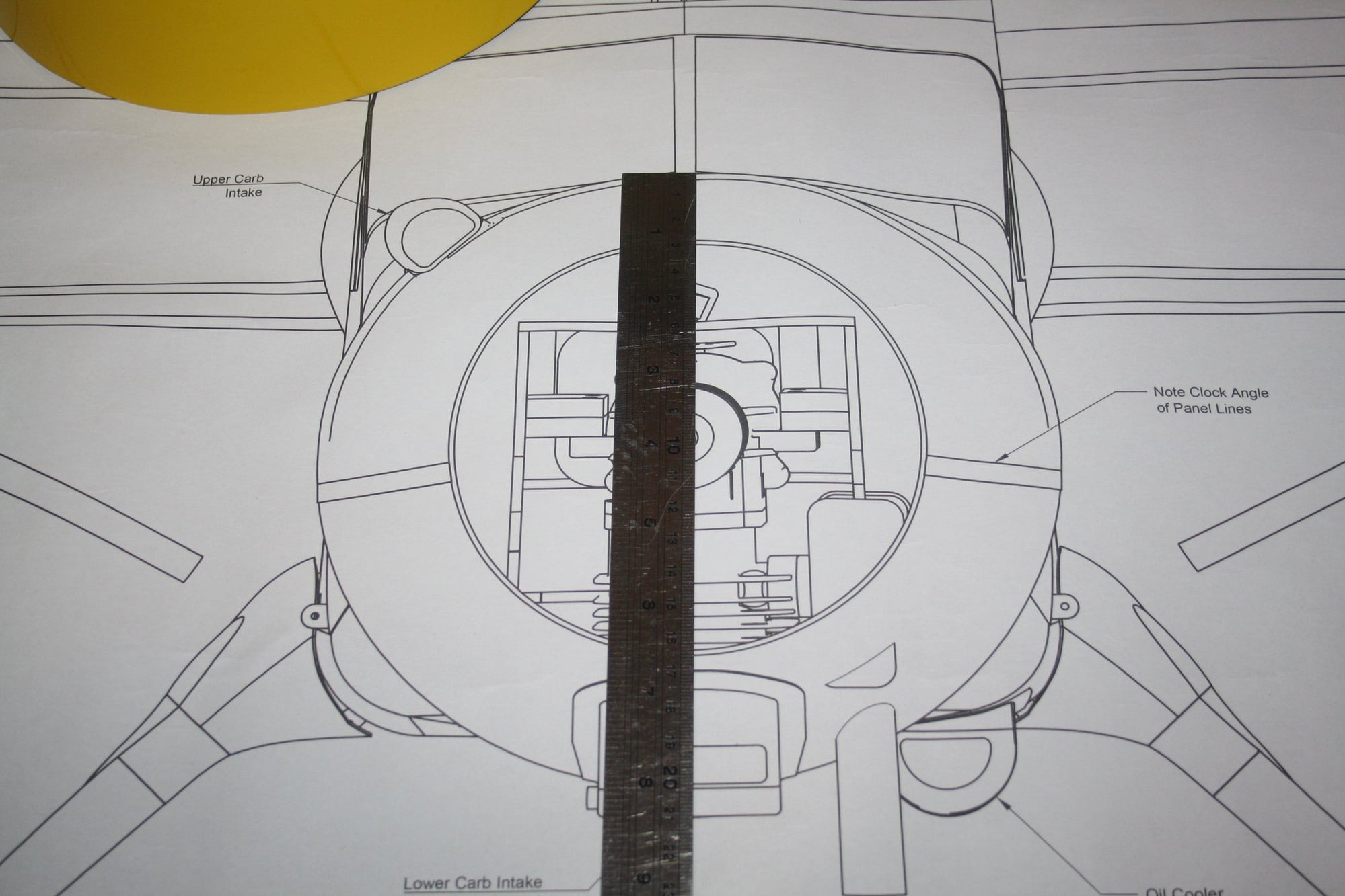
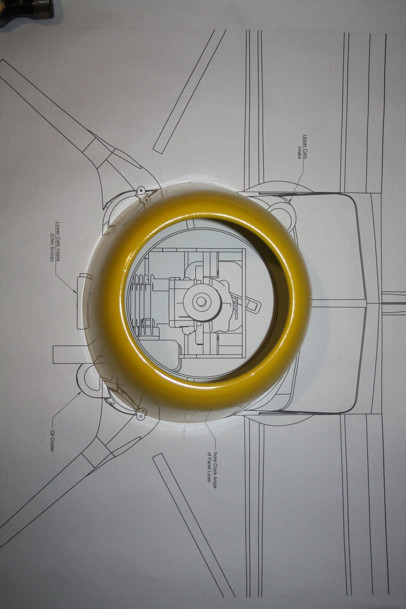
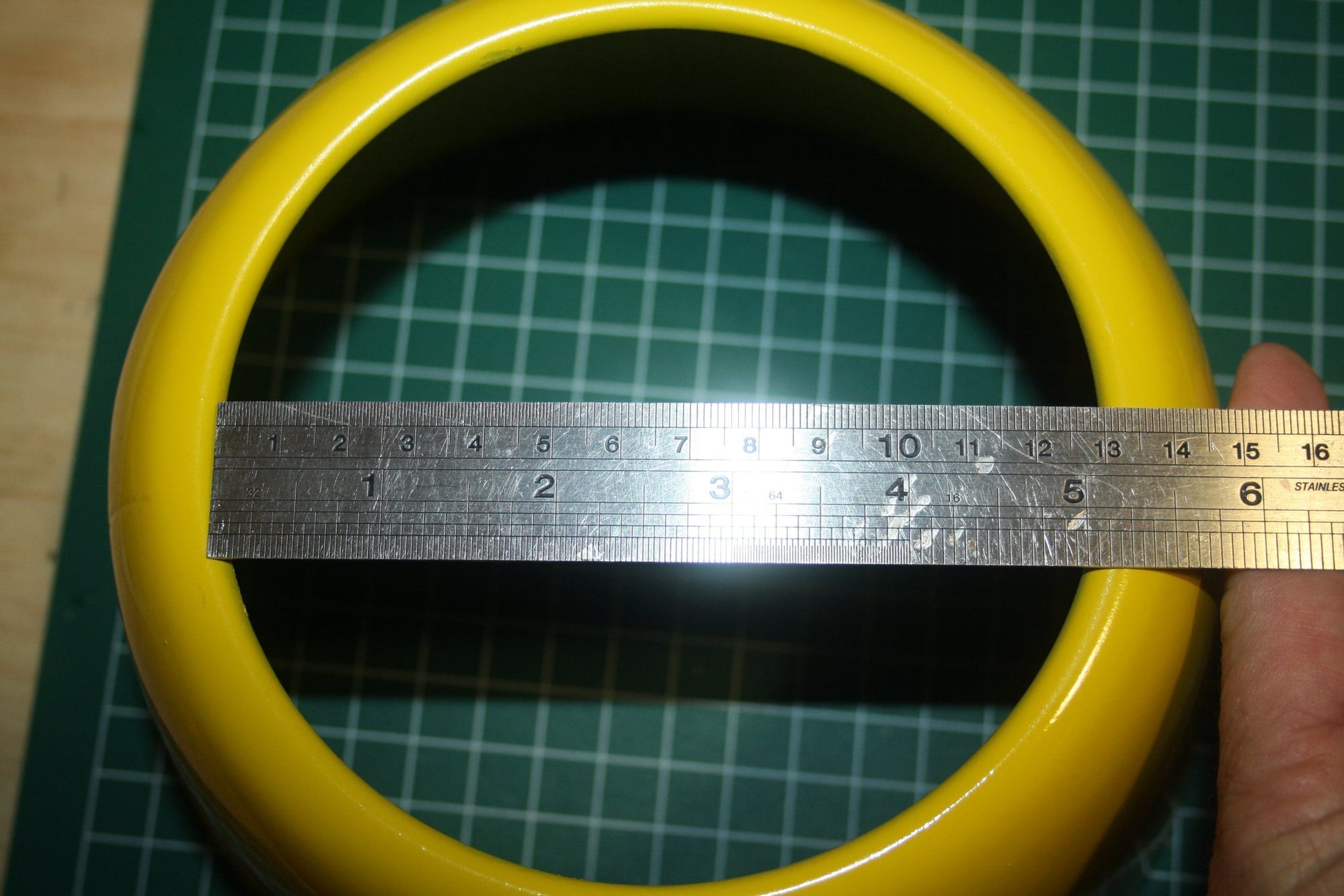
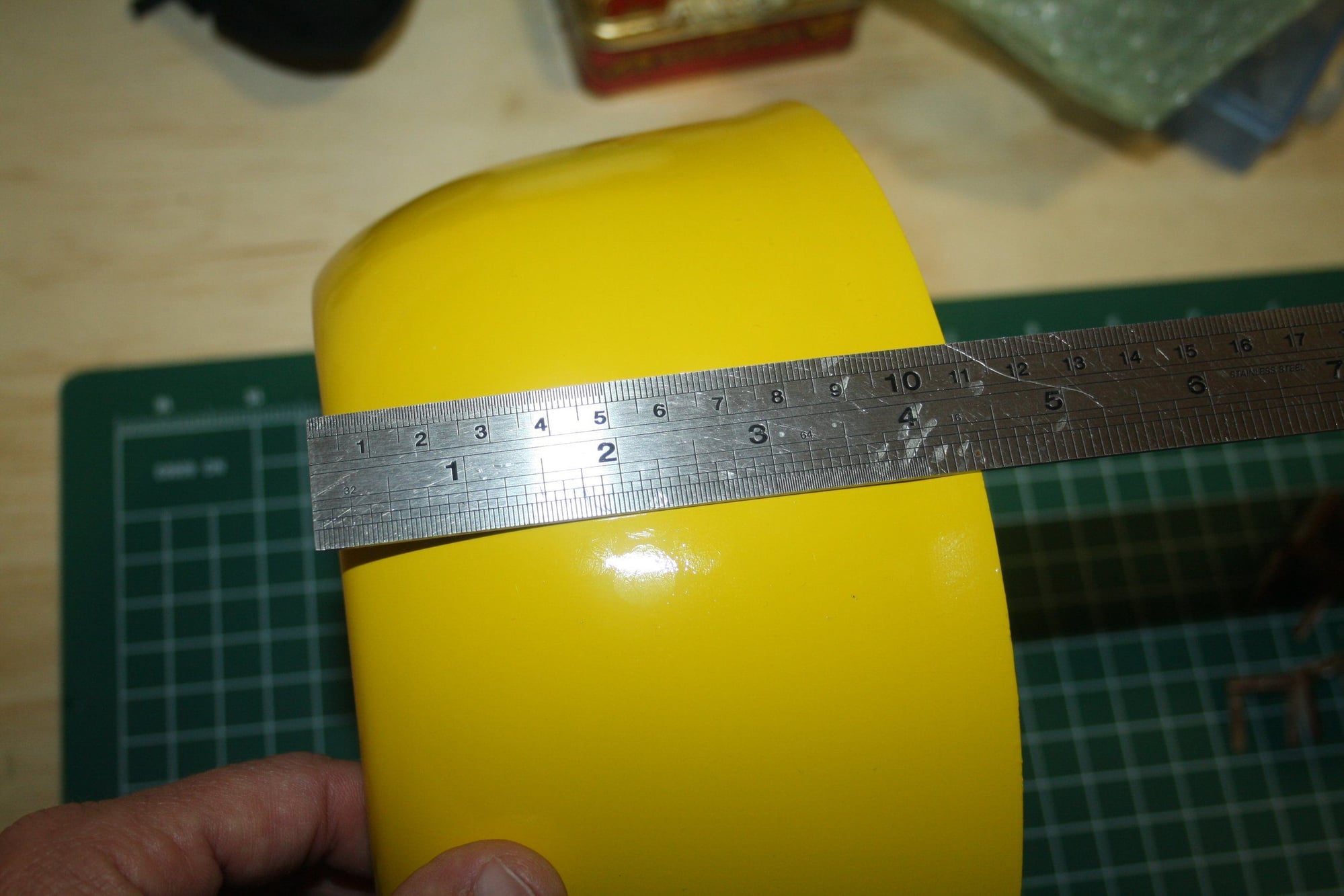
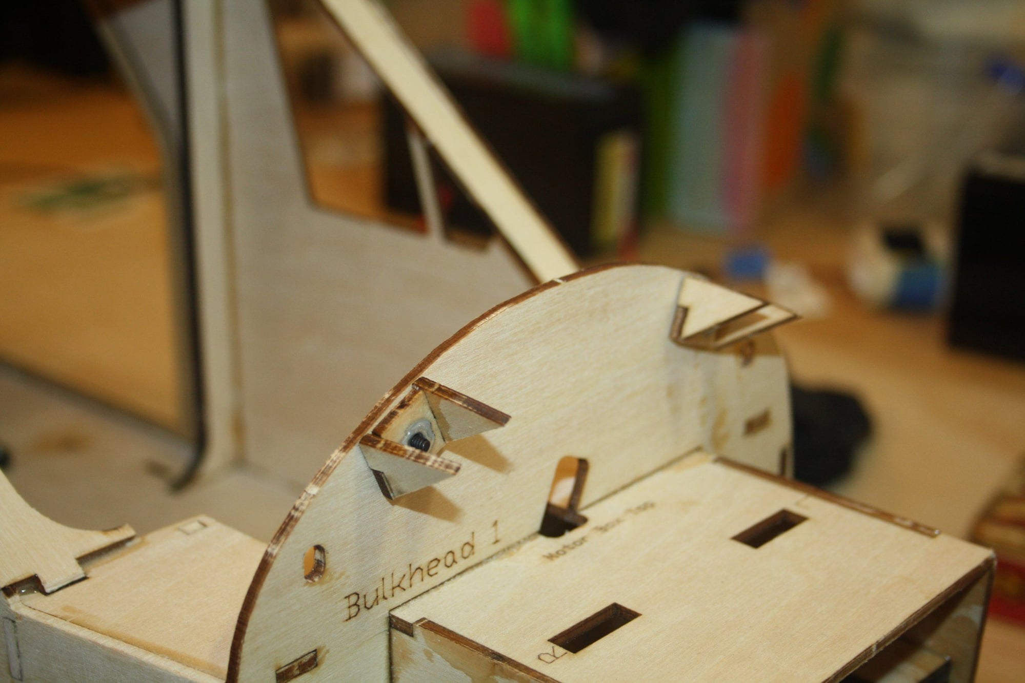
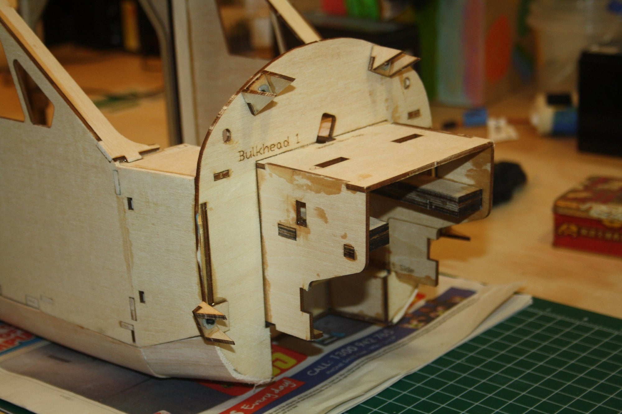
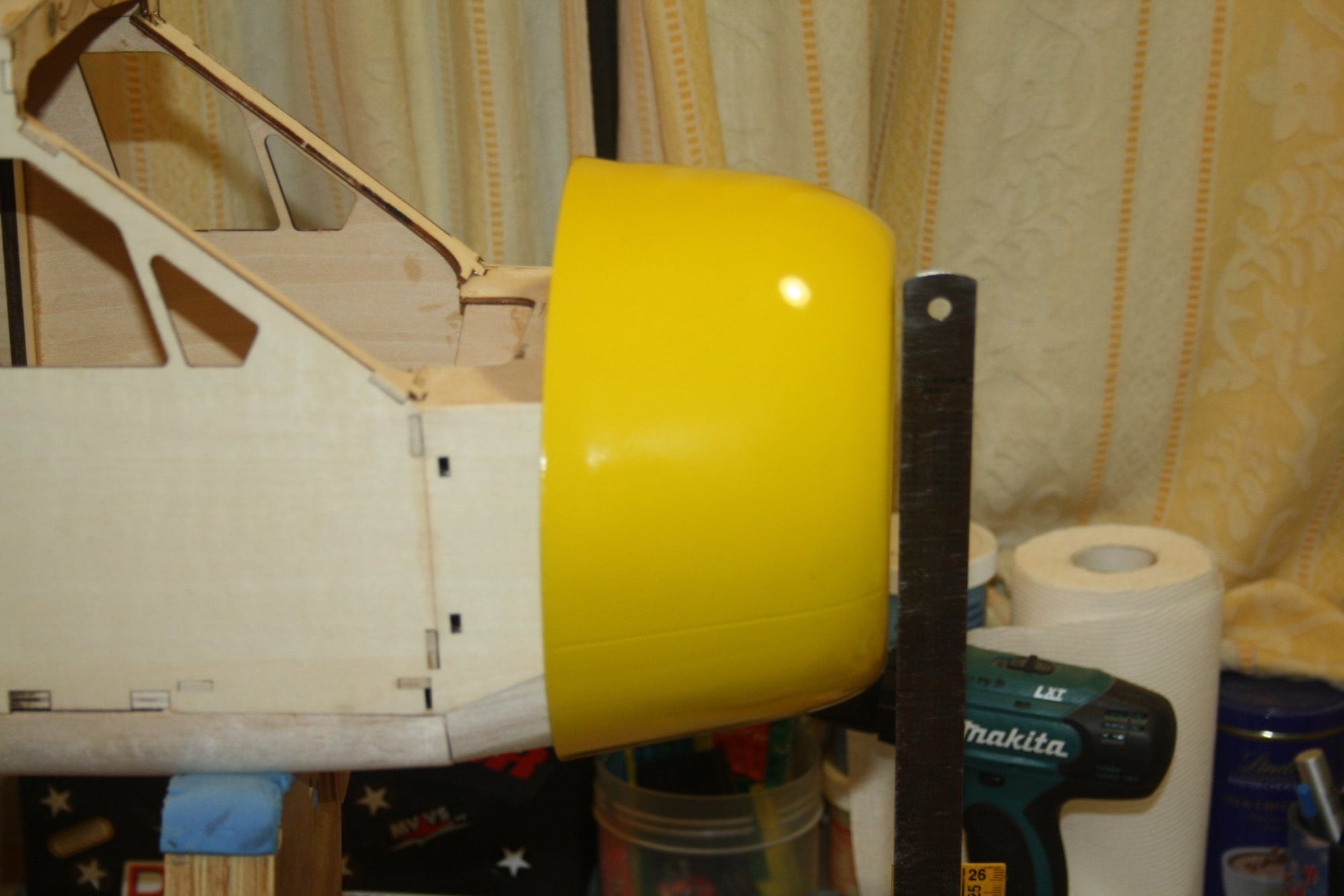
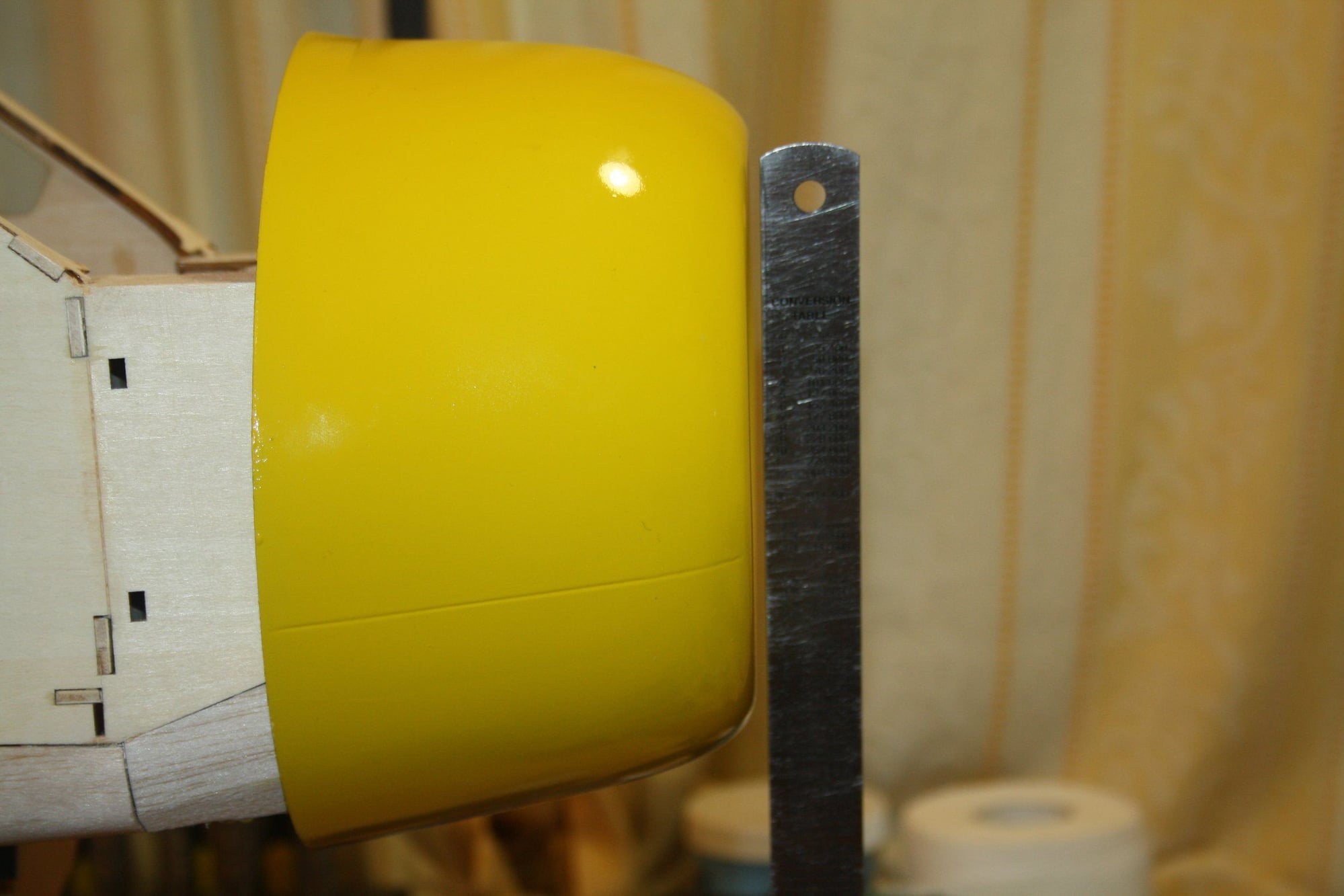
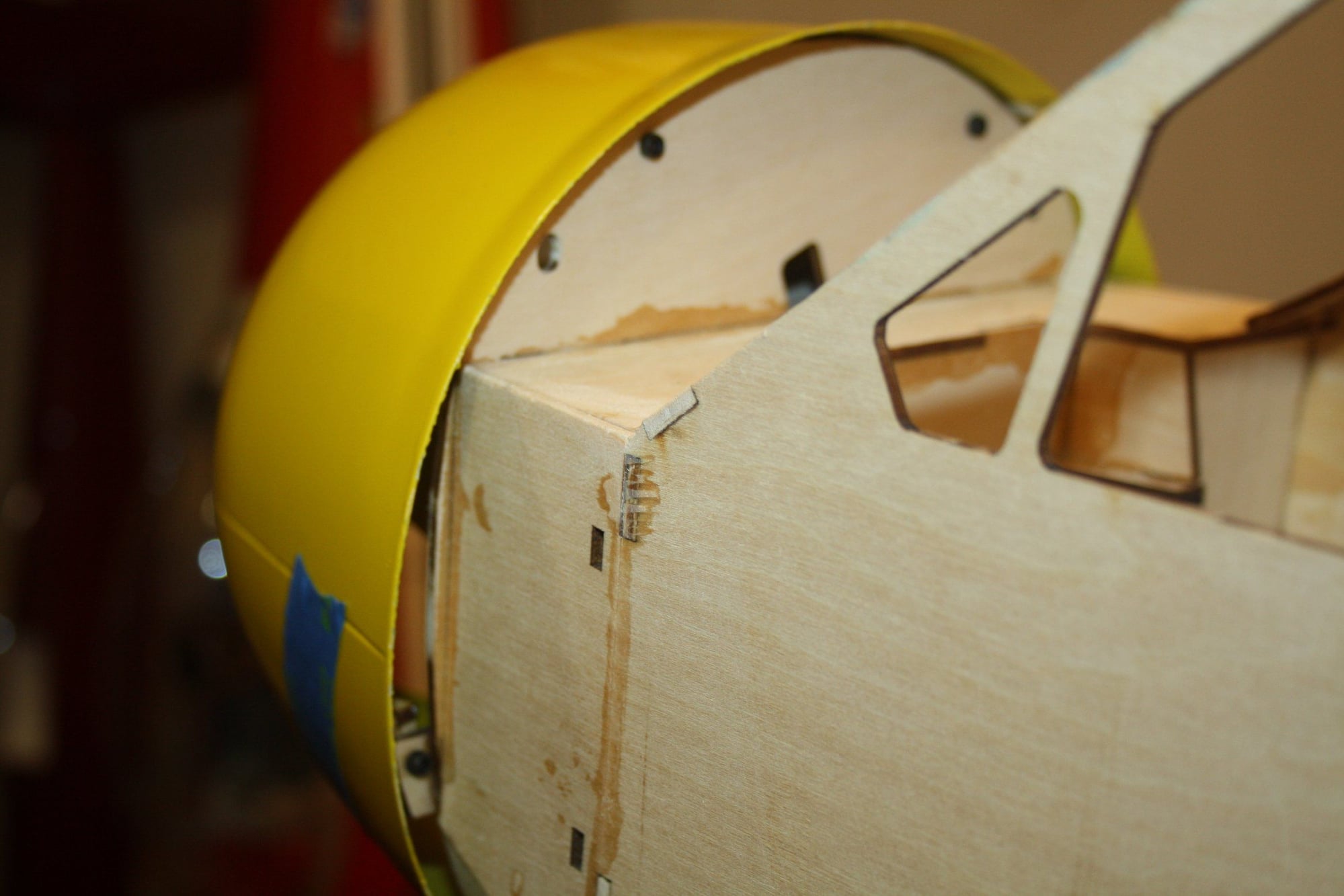
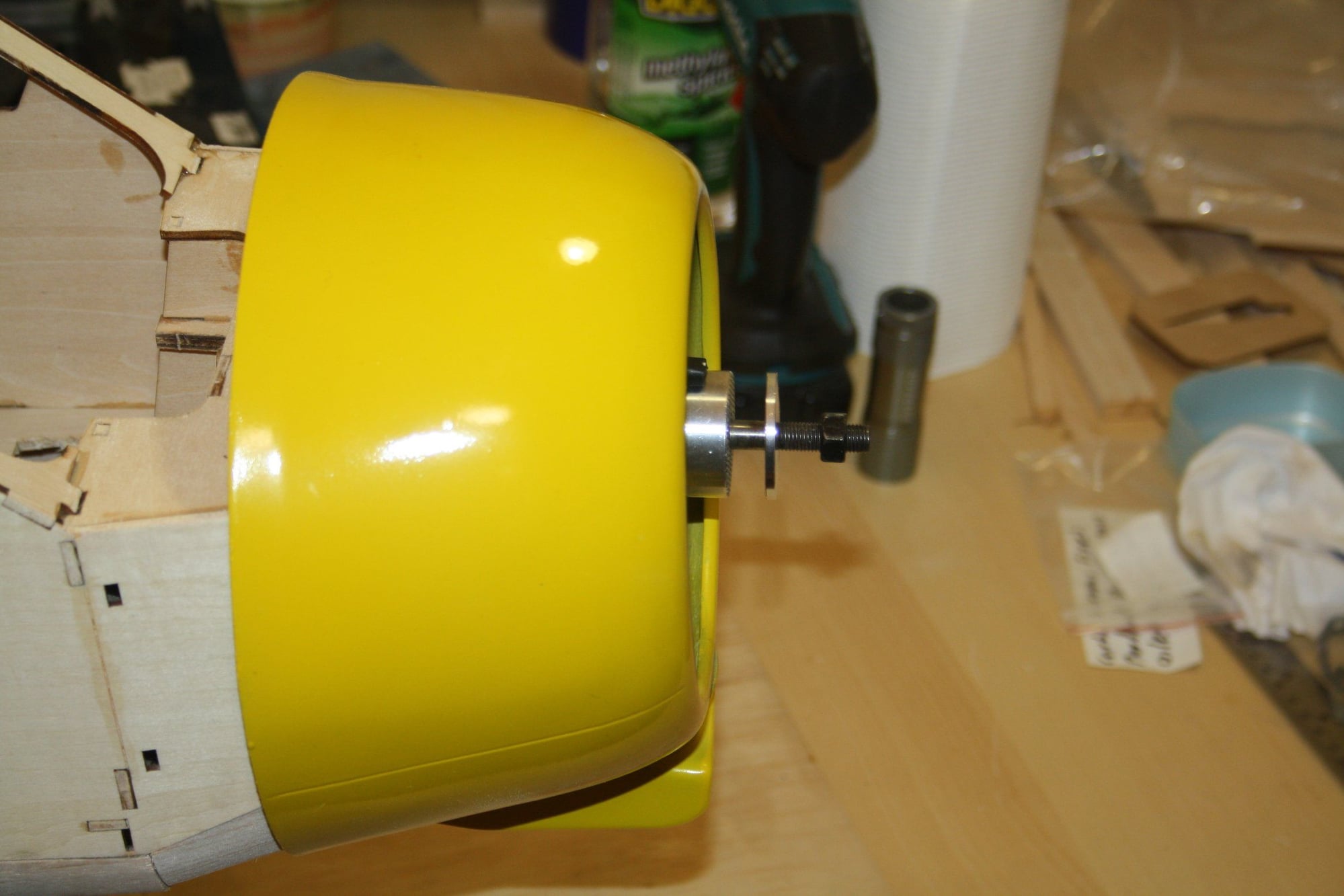
The cowl dimensions were slightly off compared with the plans, and it was slightly oval (out of round). The mounting system is satisfactory.
Cheers,
Eran
Cheers,
Eran
11-28-2022, 04:39 AM
#72
Thread Starter
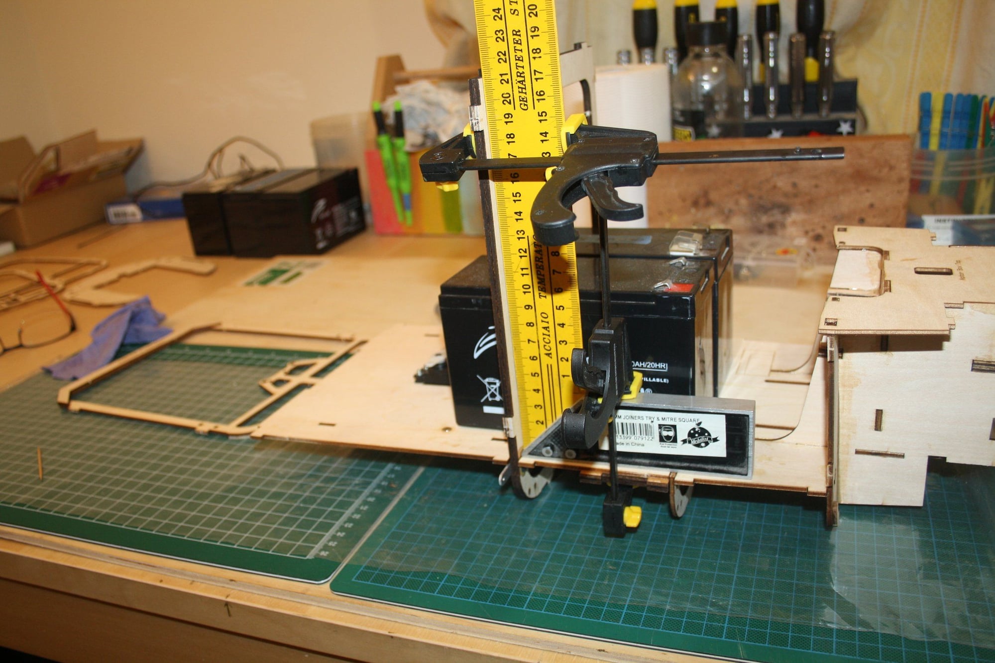
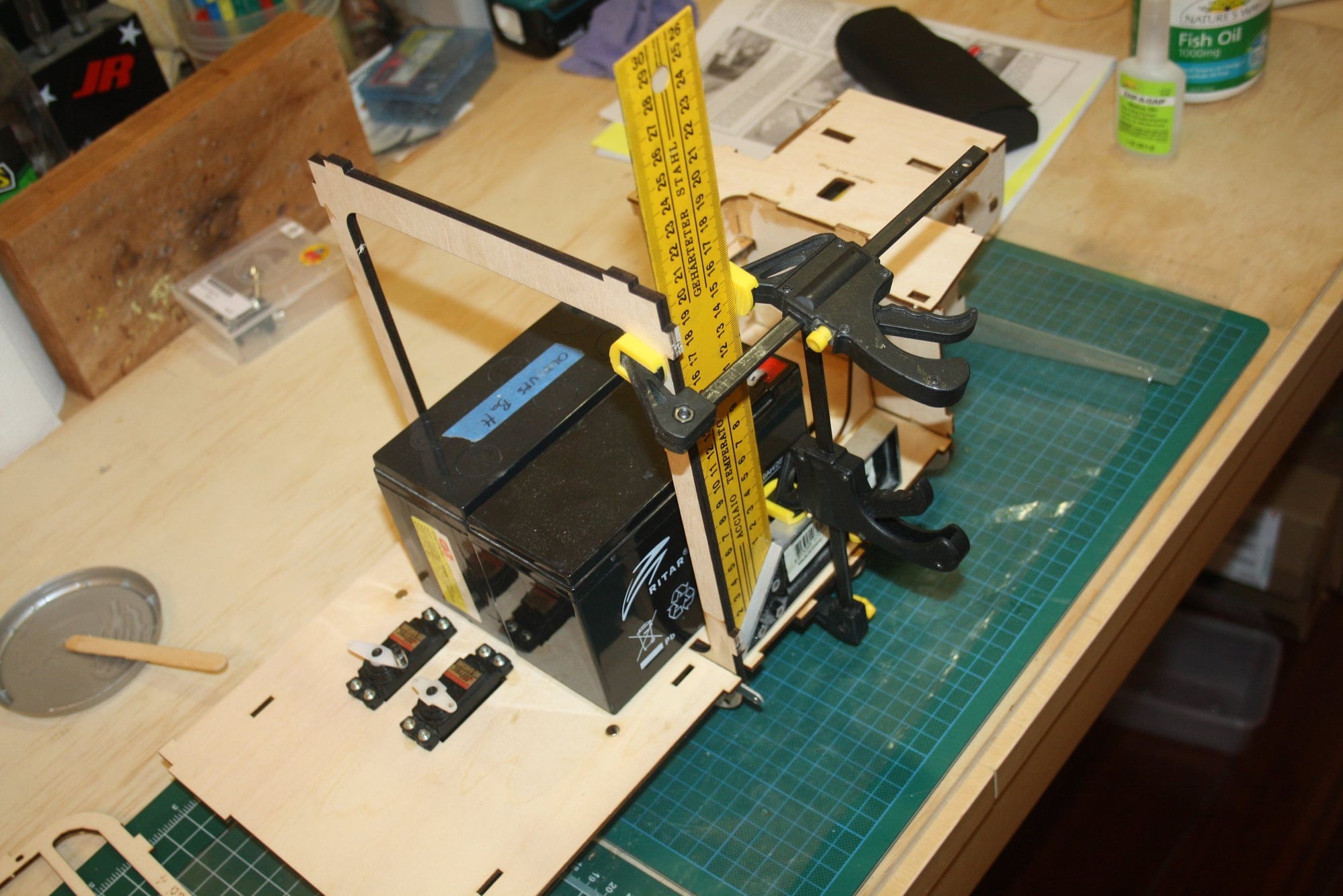
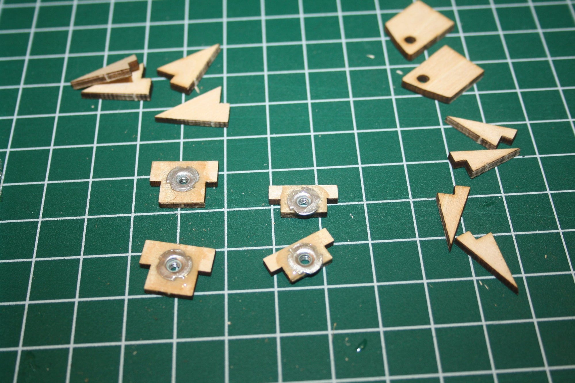
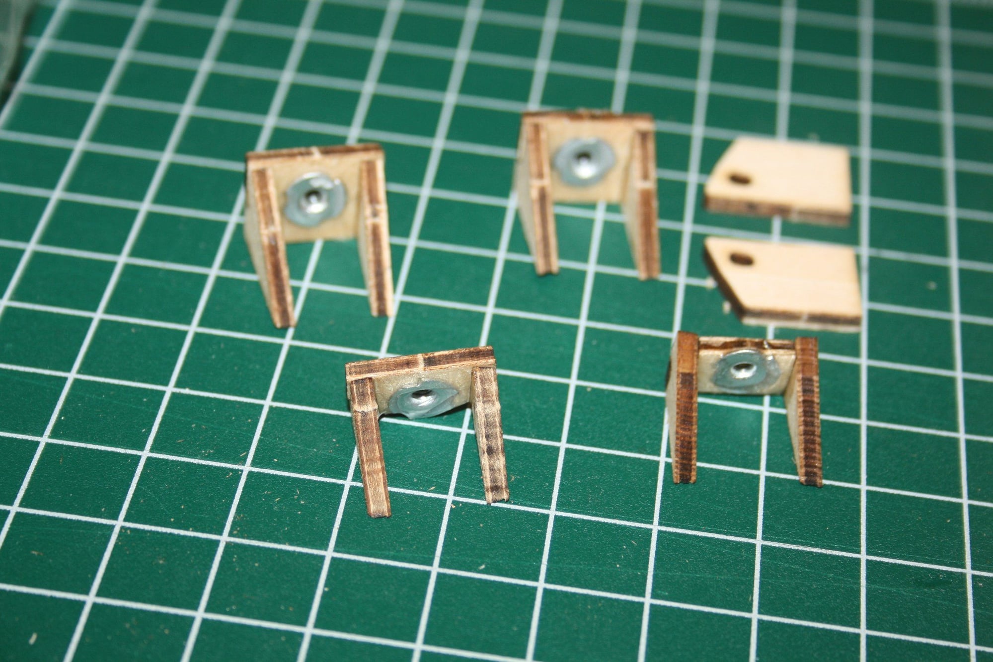
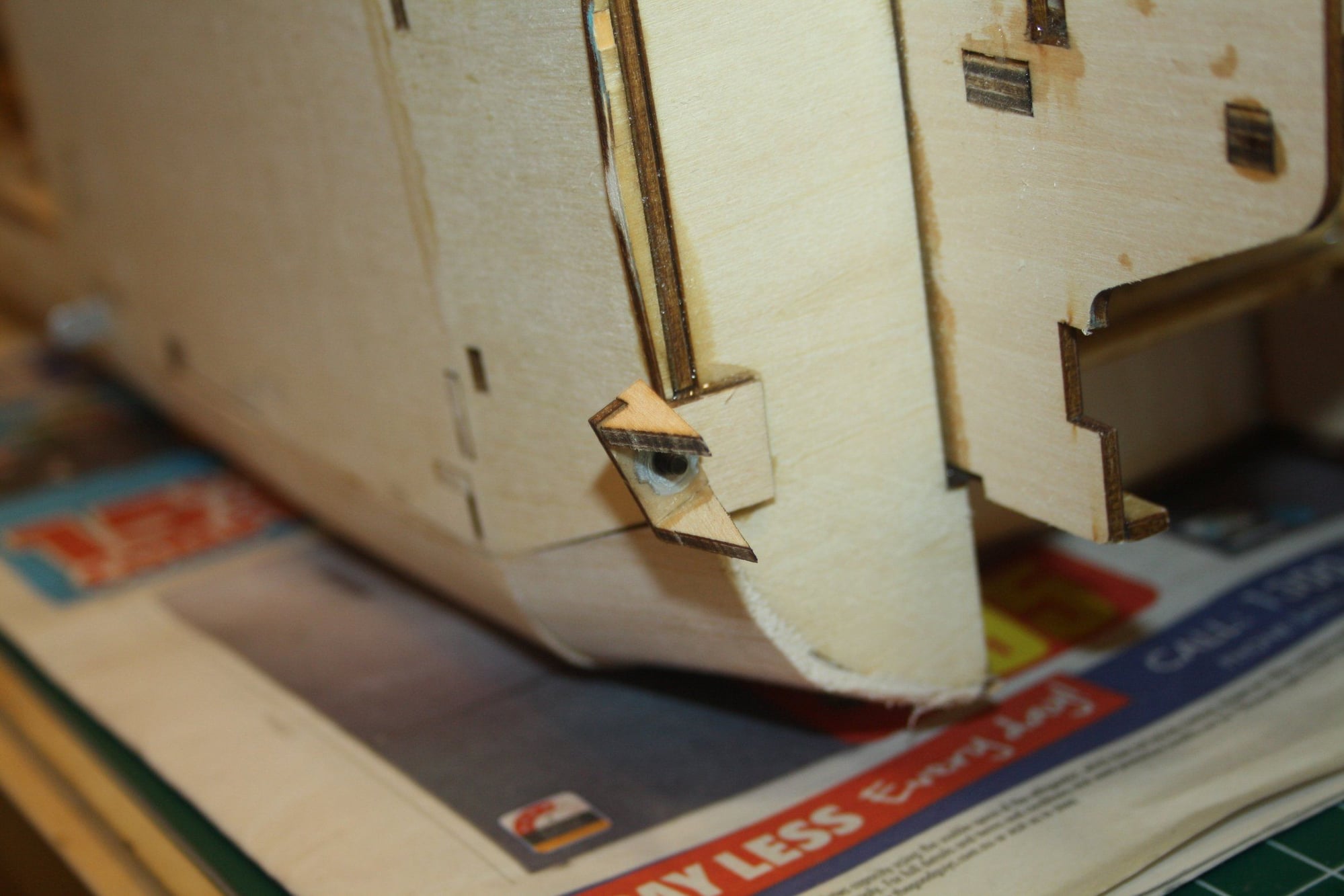
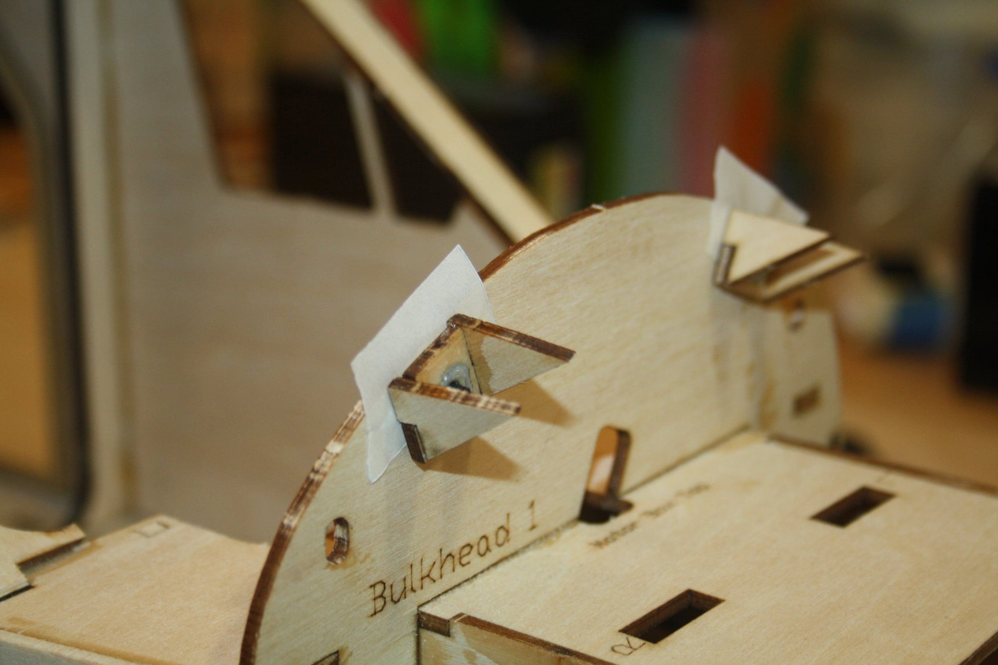
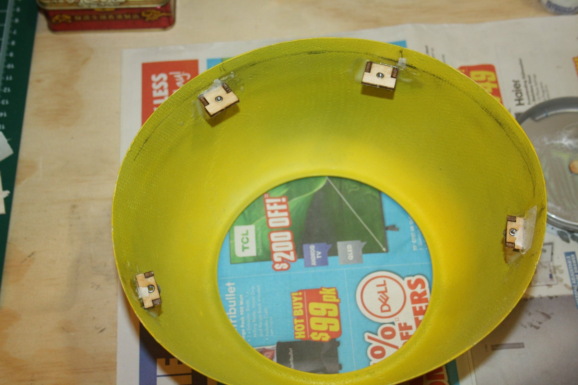
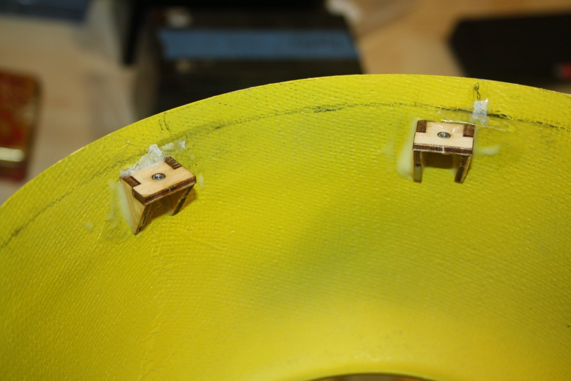
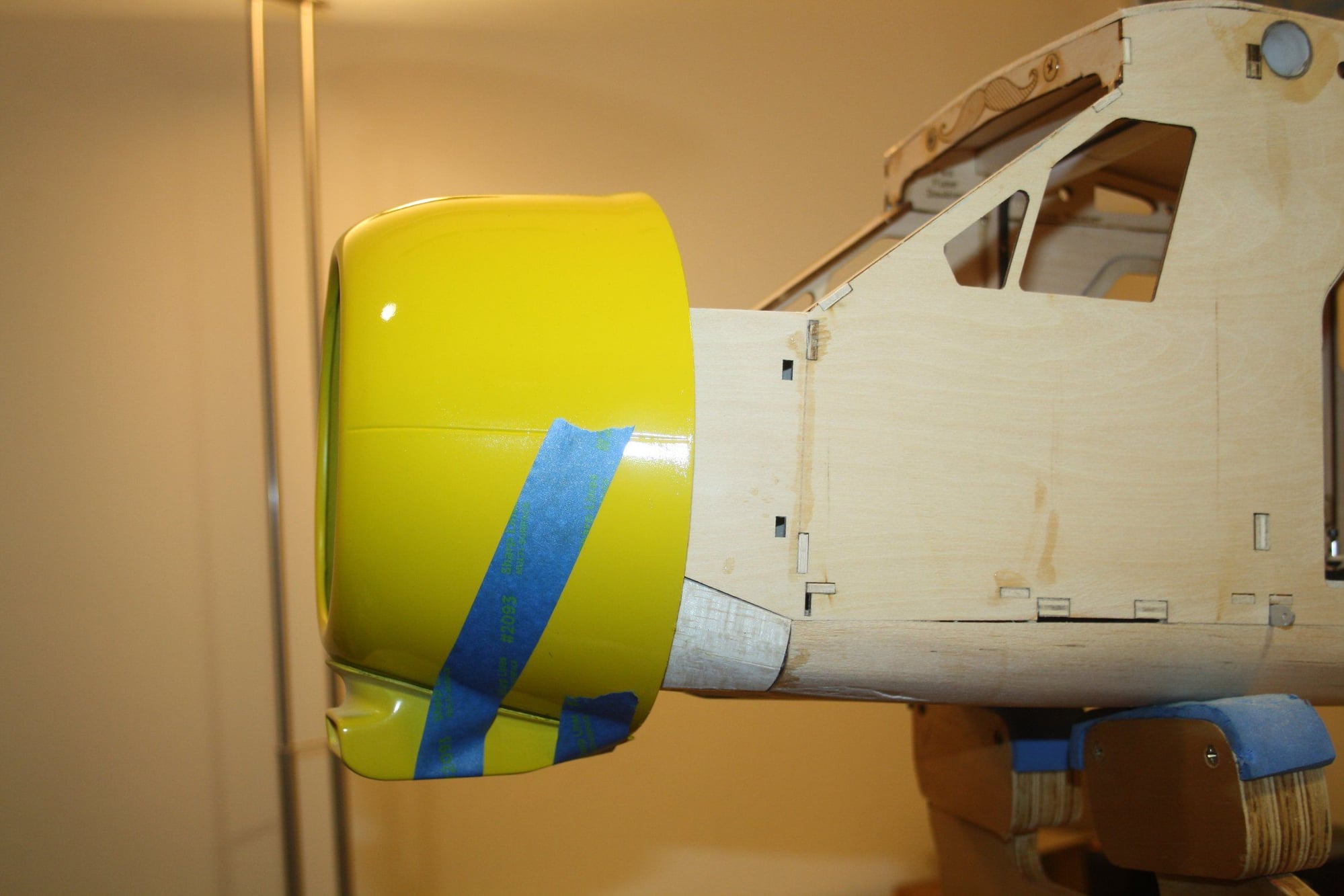
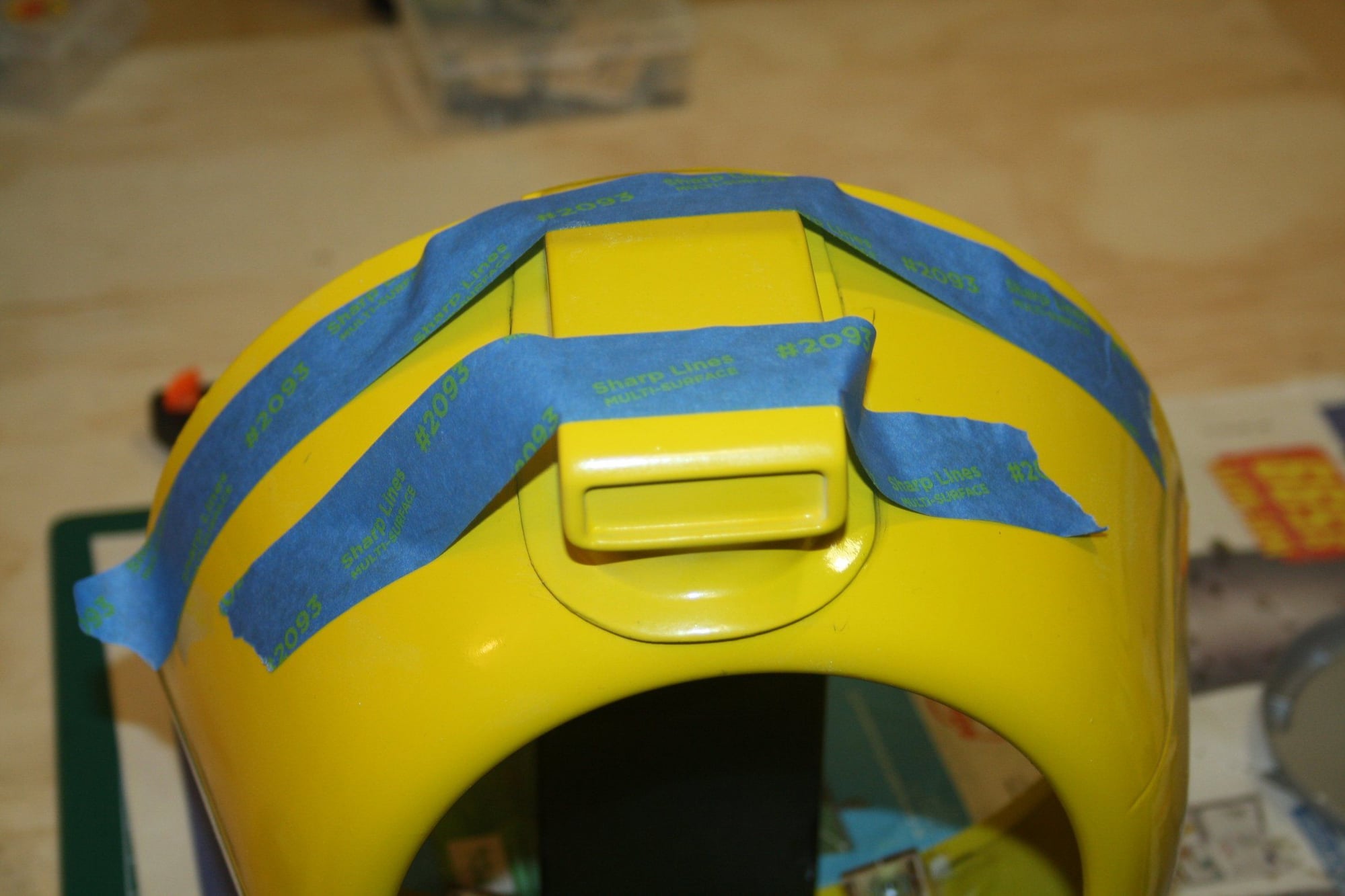
The cowl mounts are positioned in place with wax paper to prevent them being glued to the fuselage. Then the cowl is positioned on them. Using 30 minutes Epoxy, the alignment is verified and the mounts bond to the cowl.
Cheers,
Eran
Cheers,
Eran
11-28-2022, 04:42 AM
#73
Thread Starter
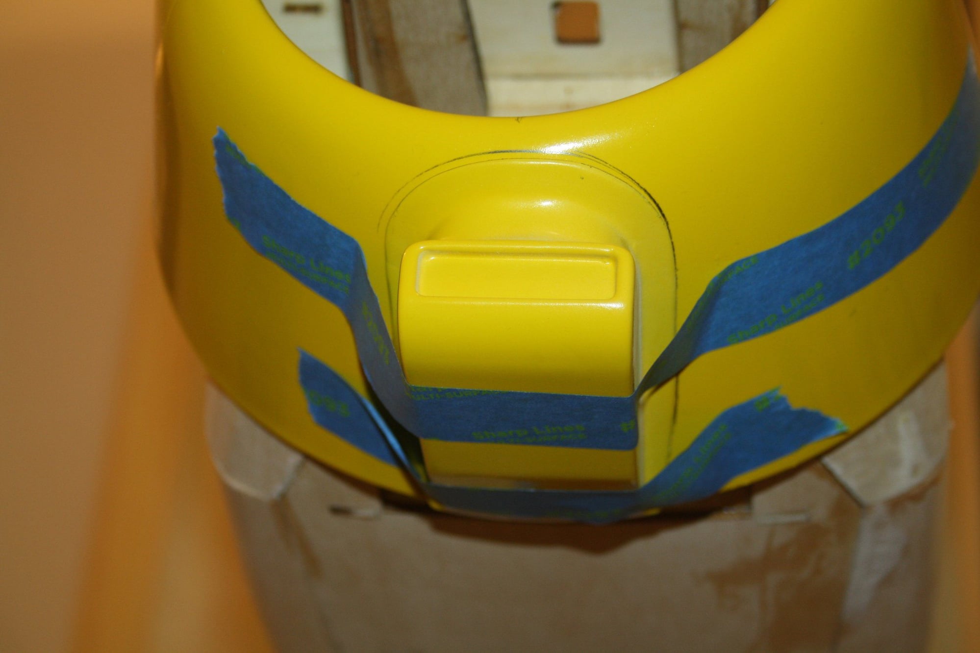
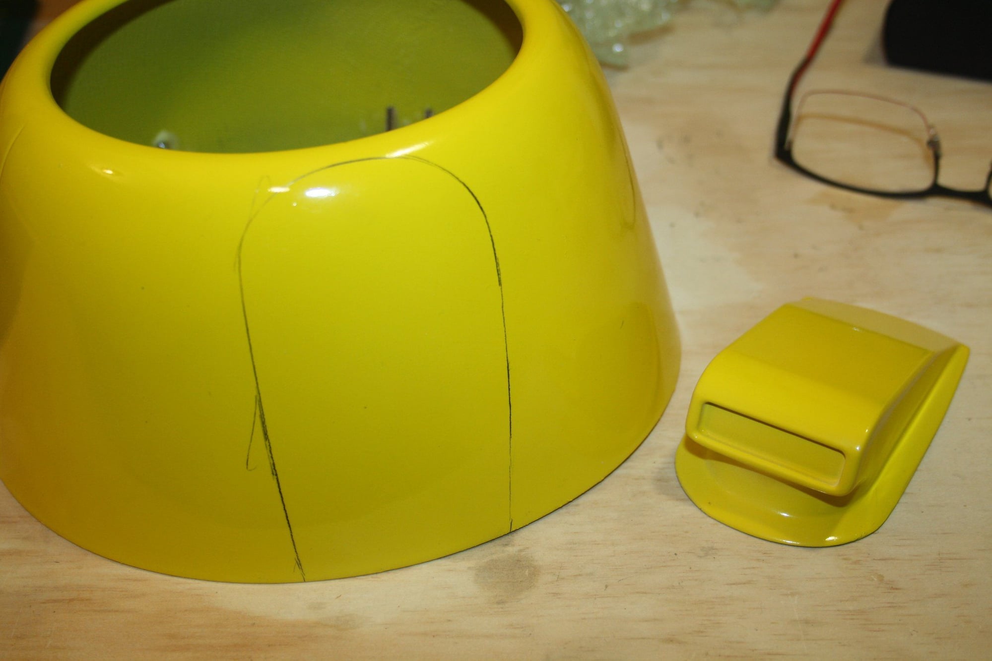
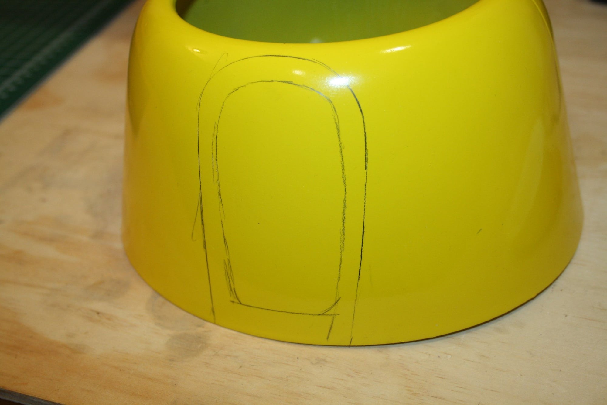
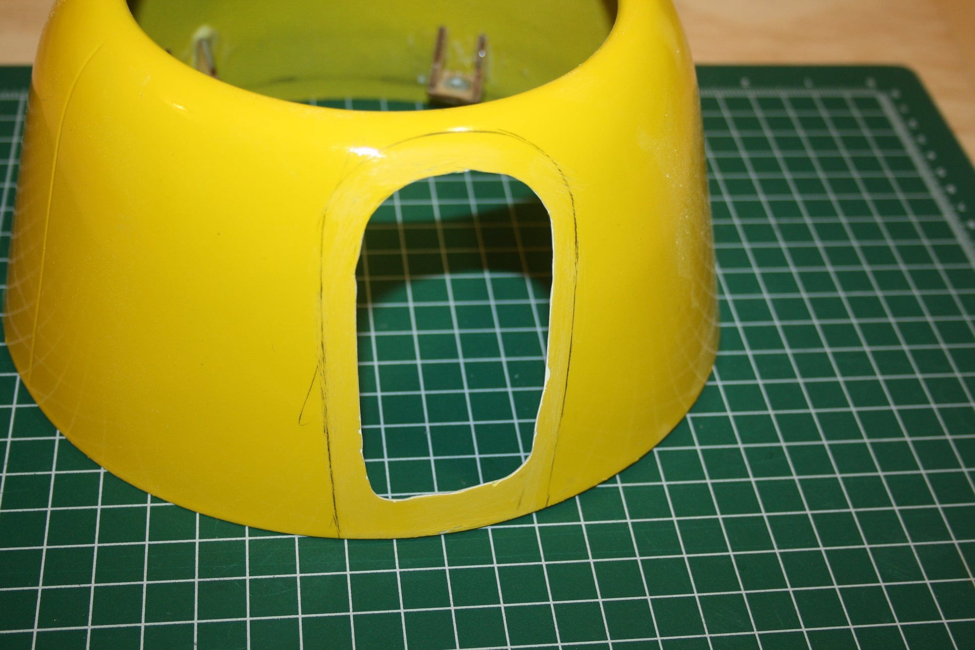
I went for the chin oil cooler, to assist in hiding the spark plug. It pays off to take the time marking everything aligned correctly before committing to cutting and gluing. The result is quite good and the gap required some filler.
Cheers,
Eran
Cheers,
Eran
12-04-2022, 01:29 AM
#74
Thread Starter
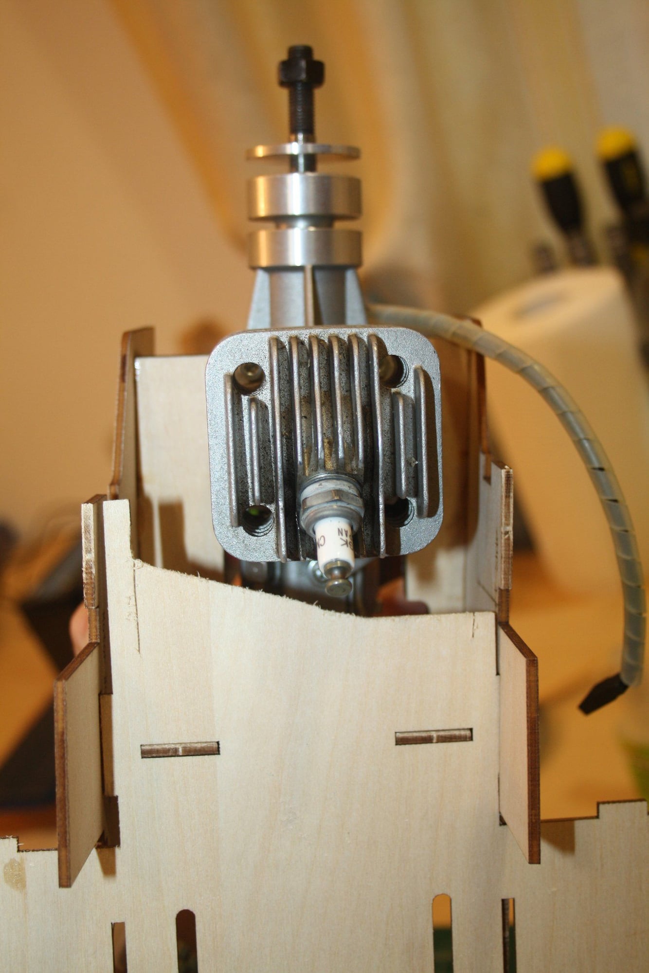
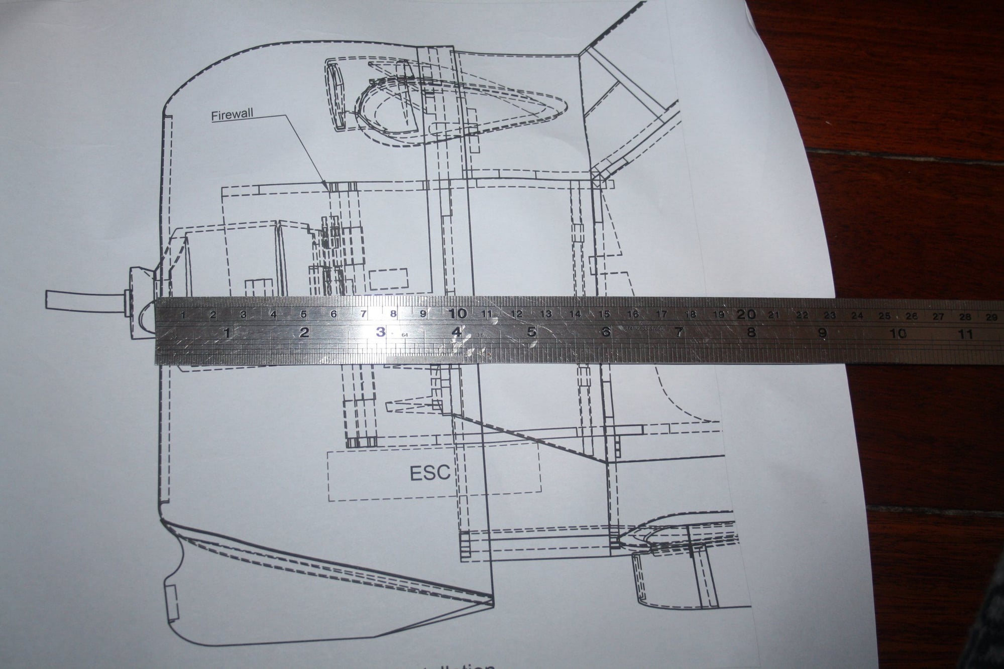
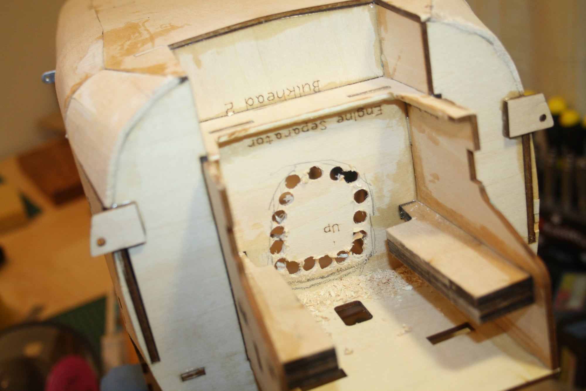
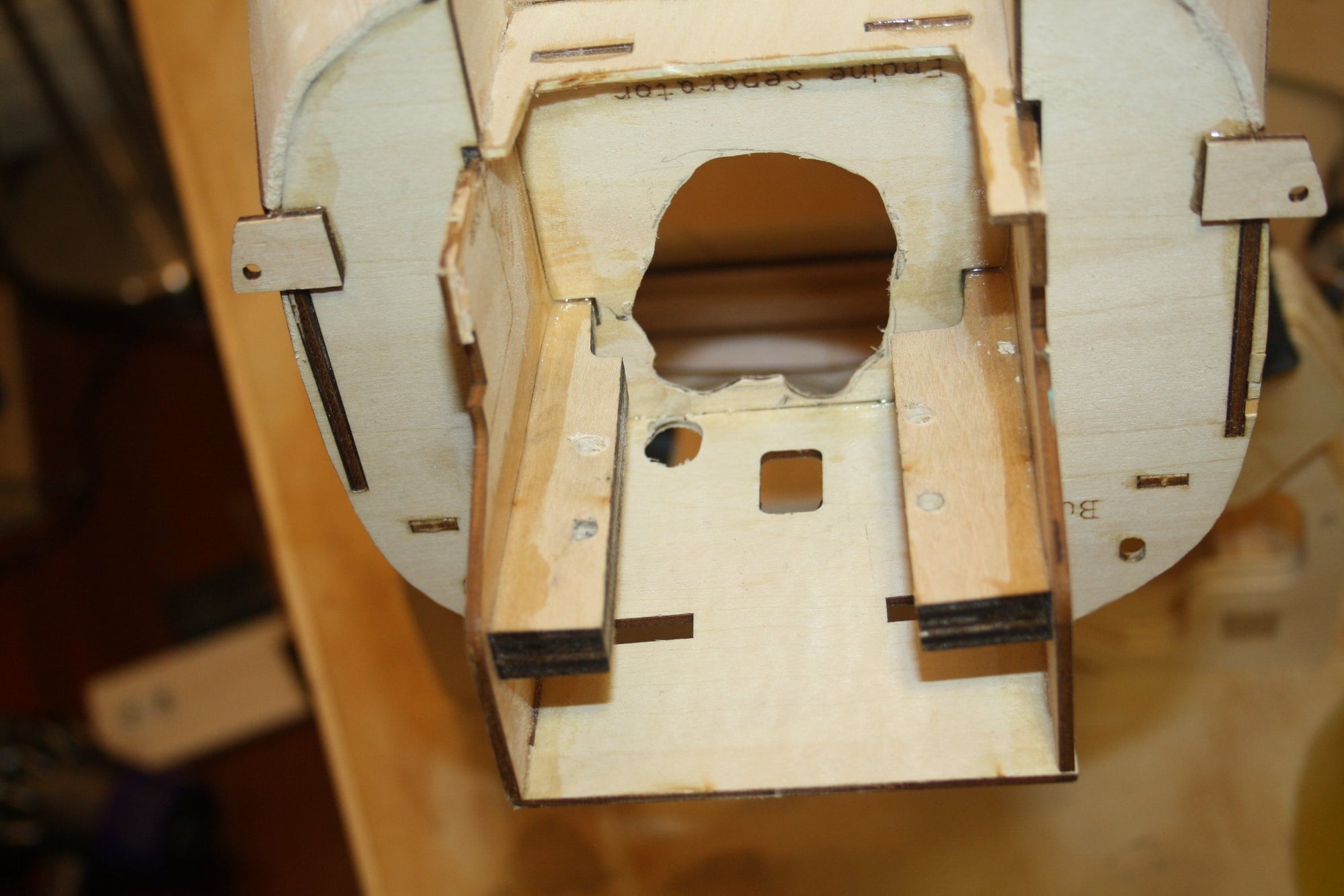
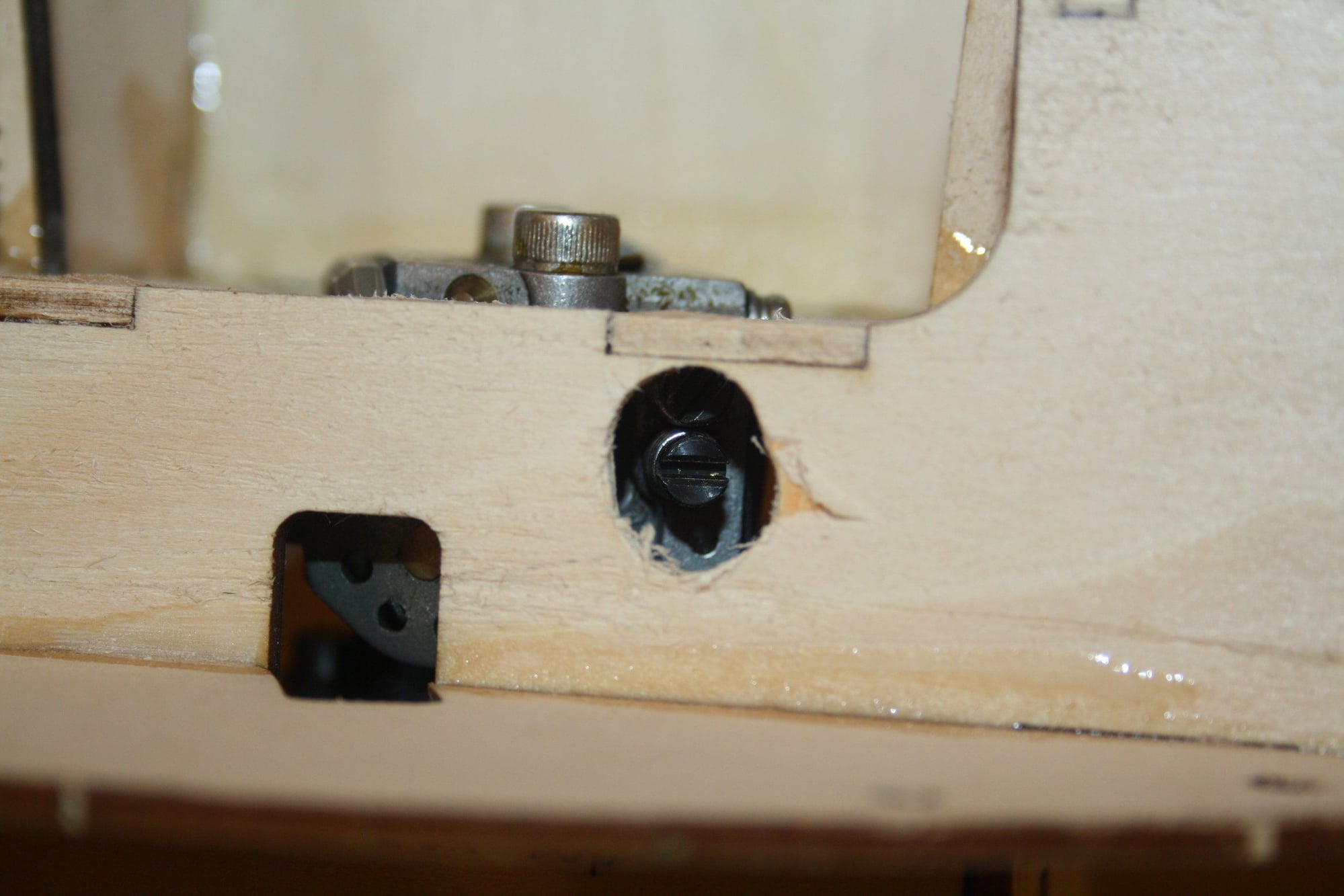
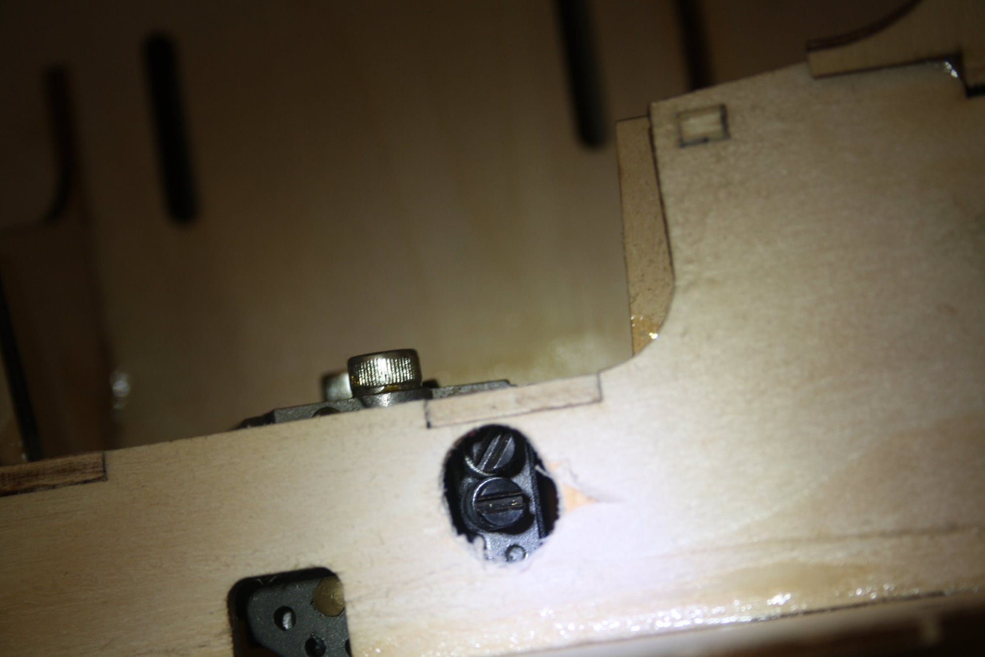
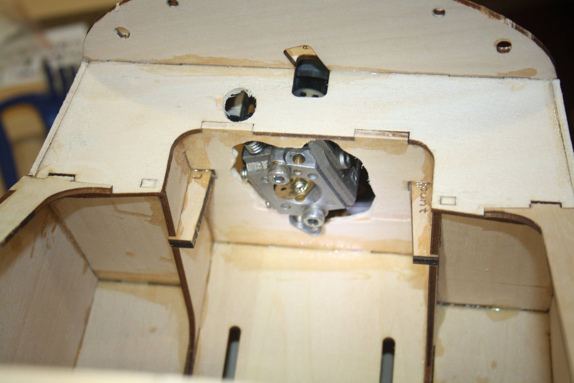
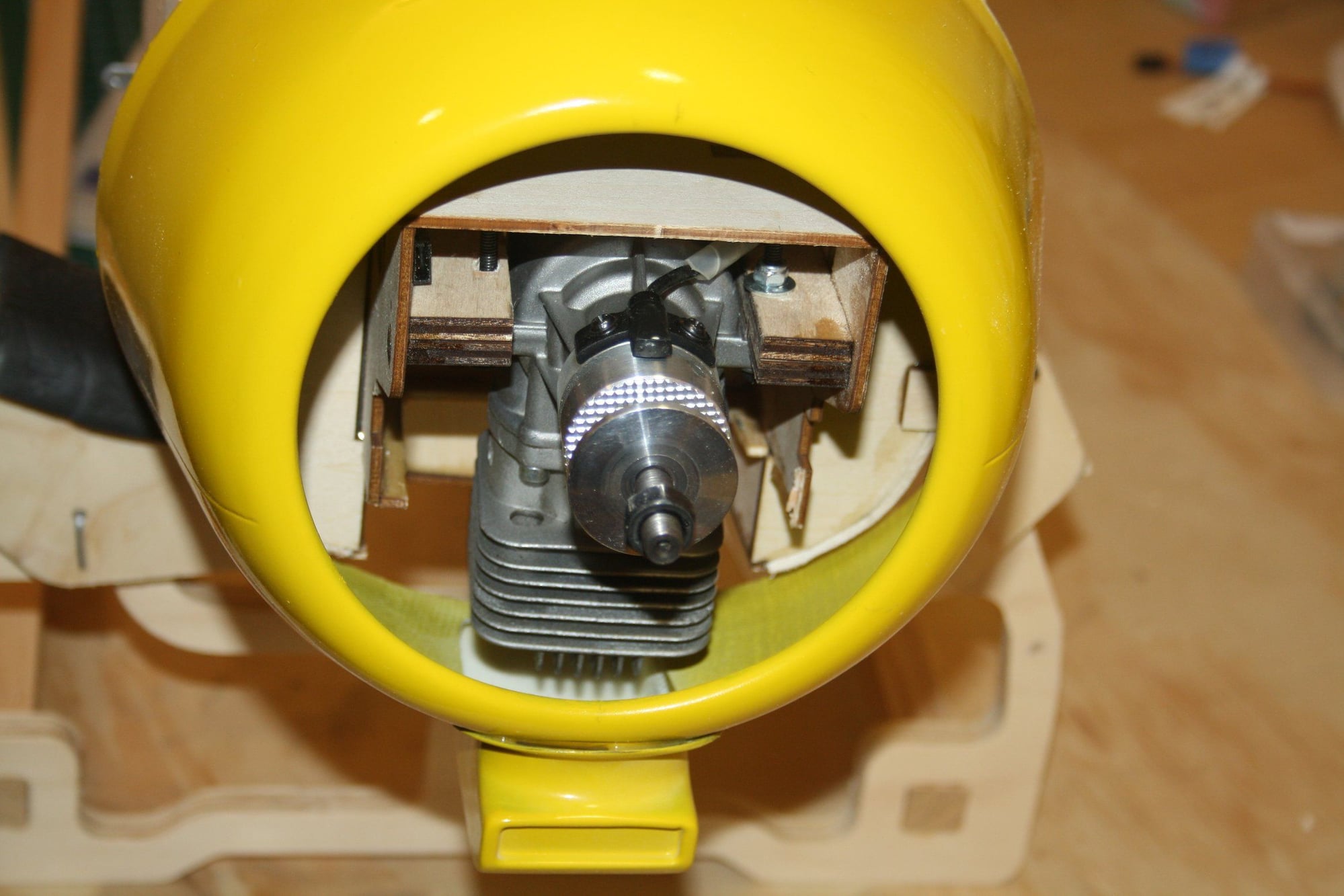
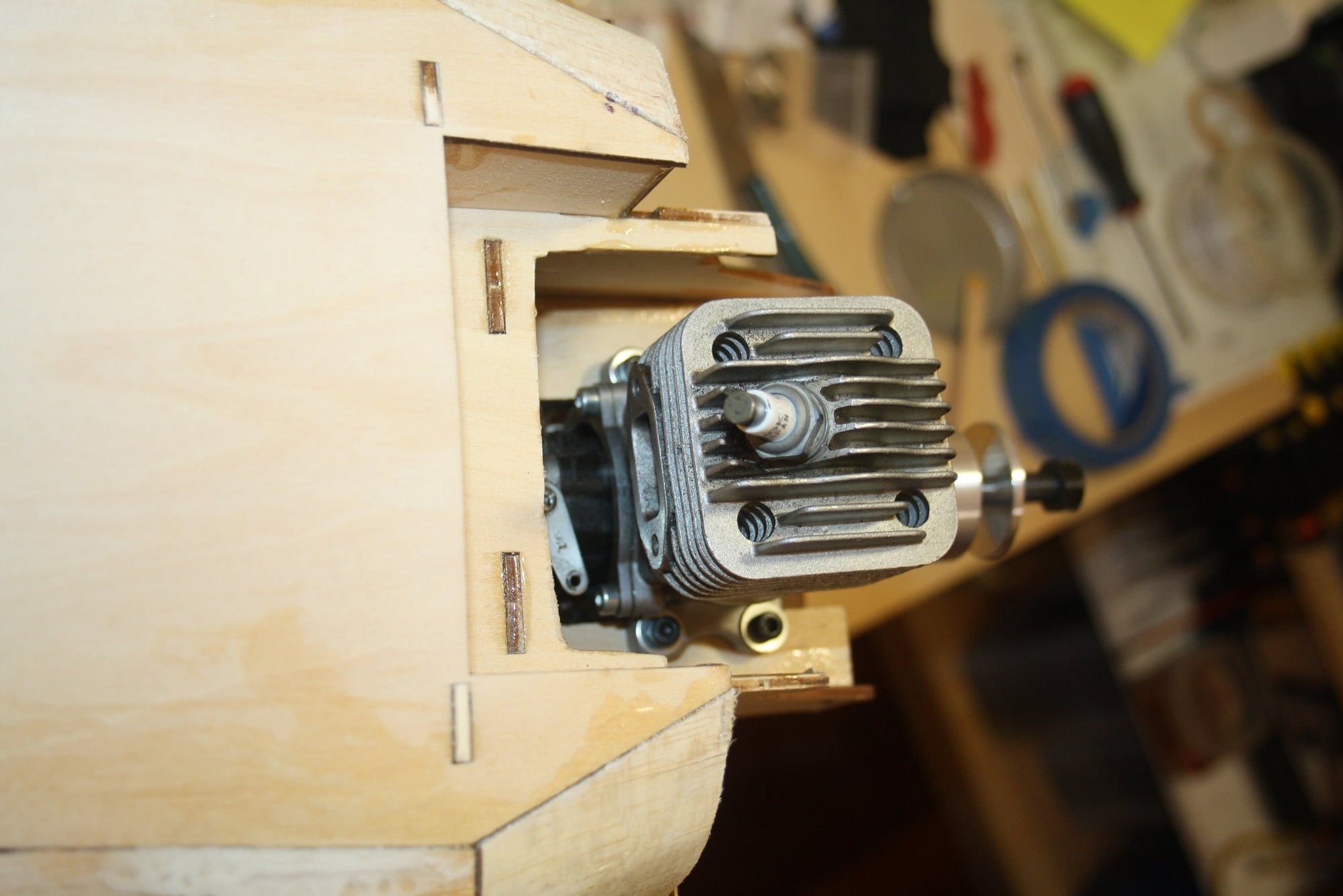
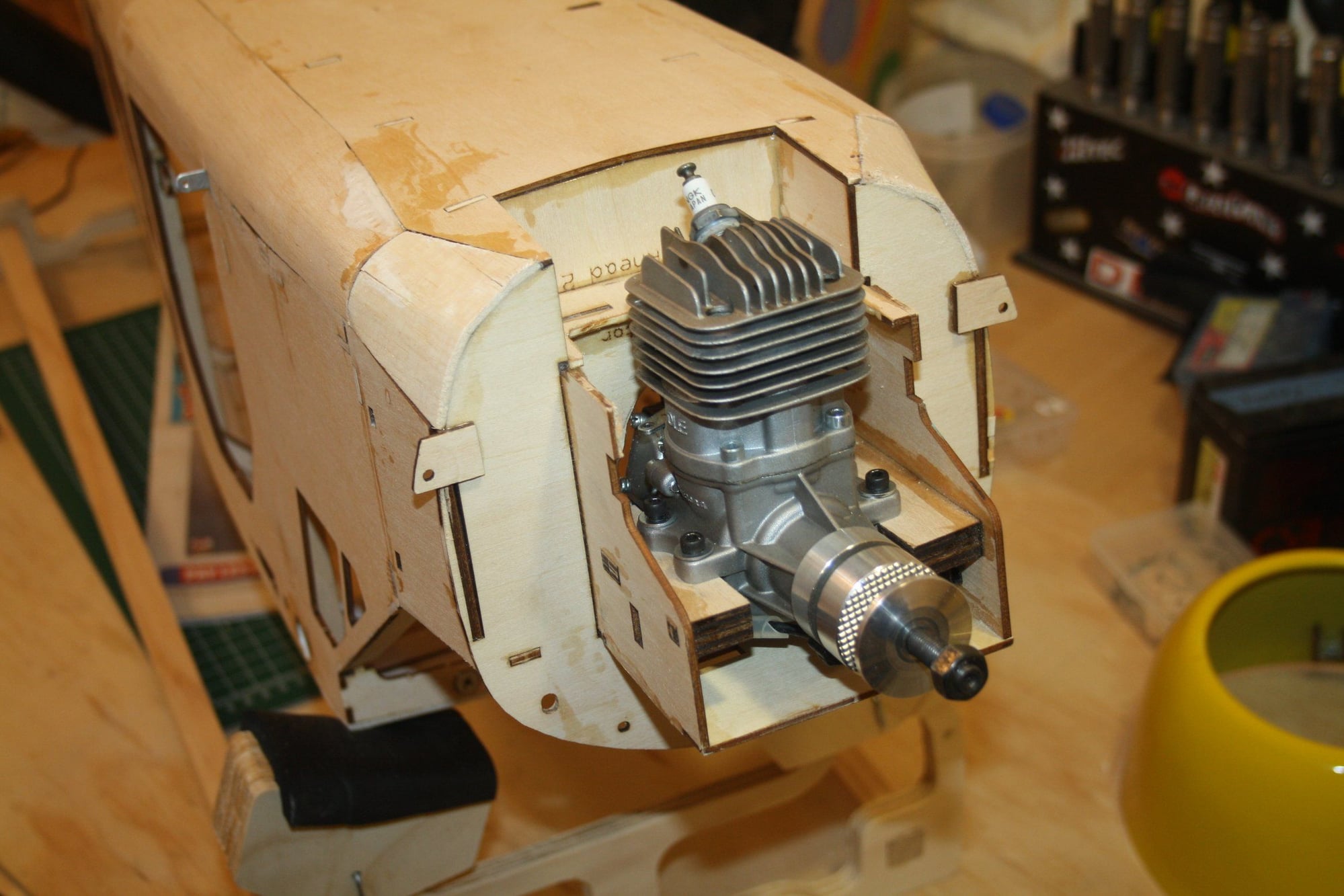
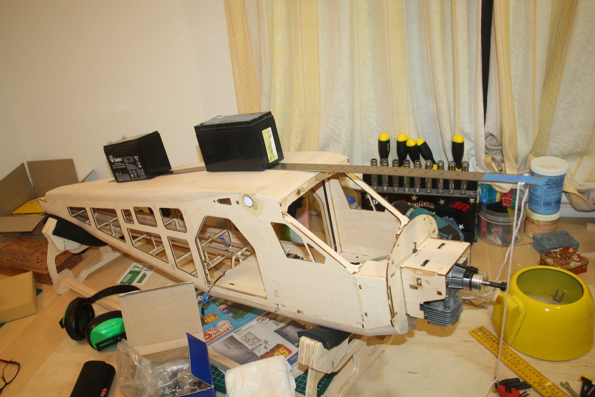
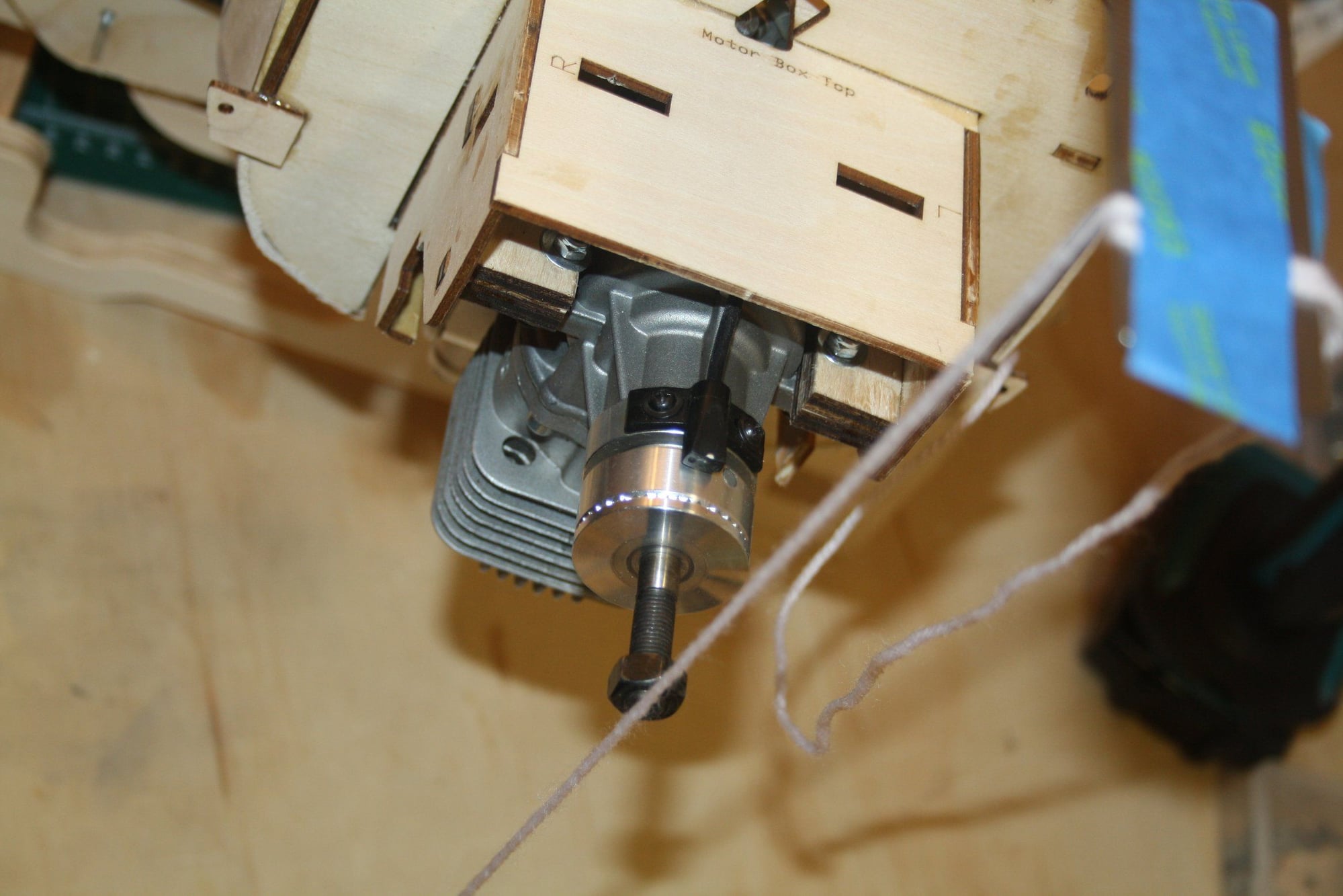
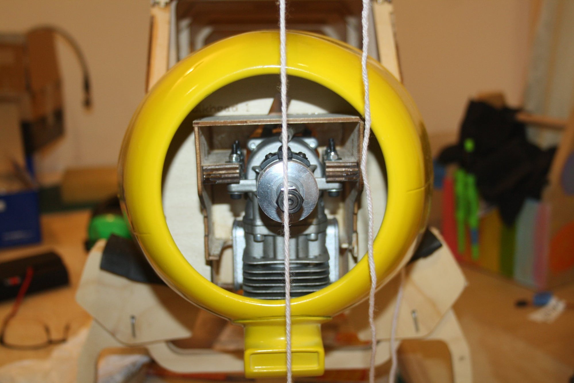
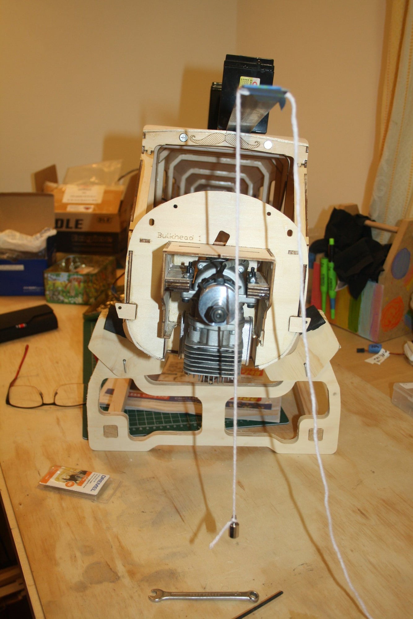
When checking the engine mounting position, I noticed that the engine protrudes forward of the cowl much further than I would have liked. This is where I made the mistake of attempting to mount it as far back as possible. To achieve this I cut a hole in the firewall for the carburettorand access holes for the adjustment screws. I completely got it wrong as I did not count for the rear muffler... Once I realised my mistake, I mounted the engine back in the designed location.
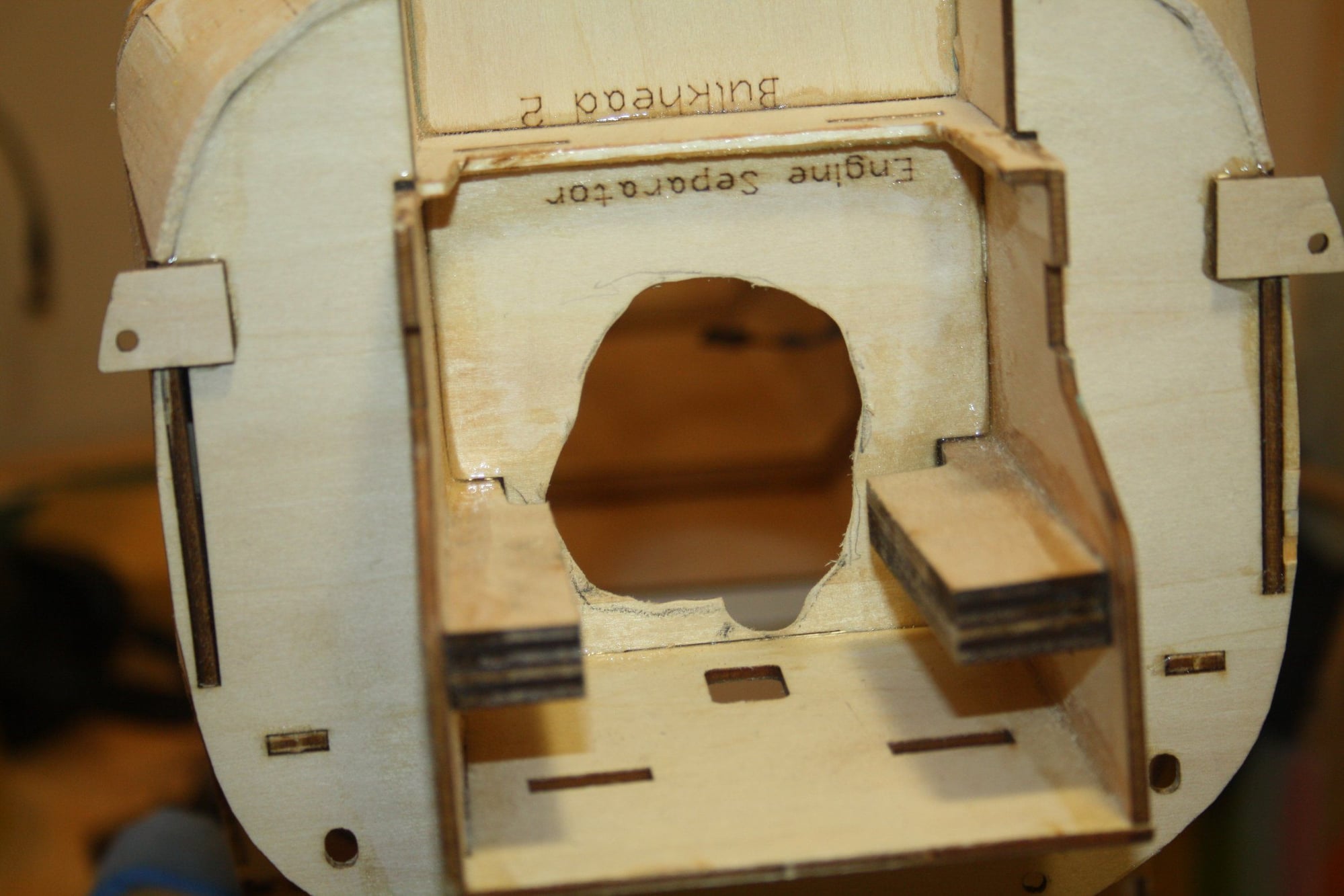
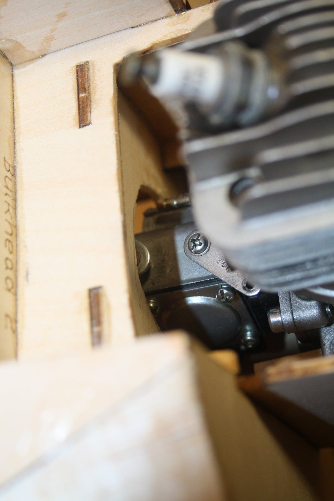
Cheers,
Eran
Cheers,
Eran
12-04-2022, 01:32 AM
#75
Thread Starter
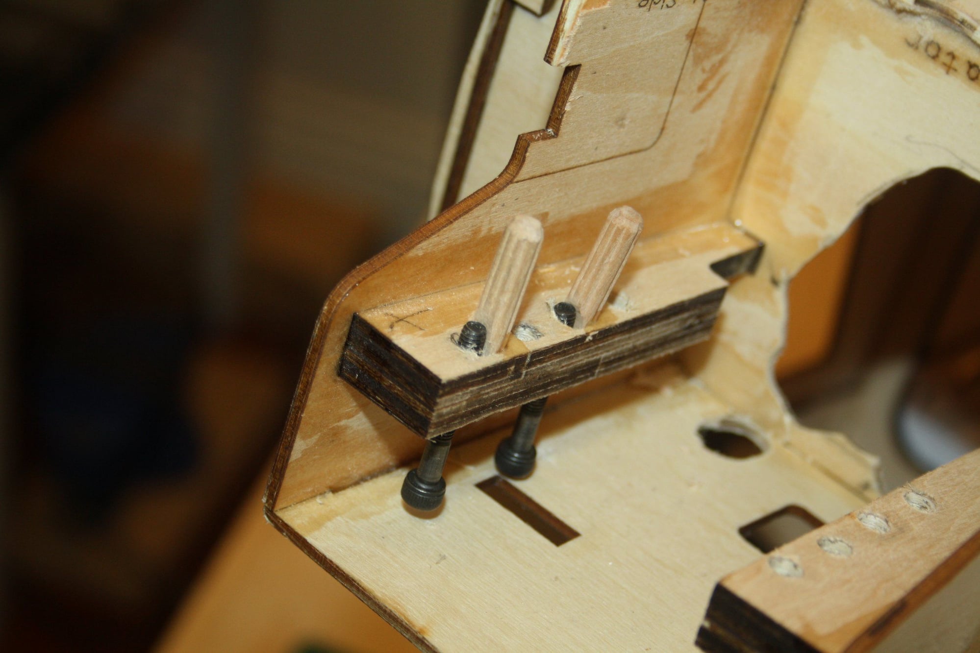
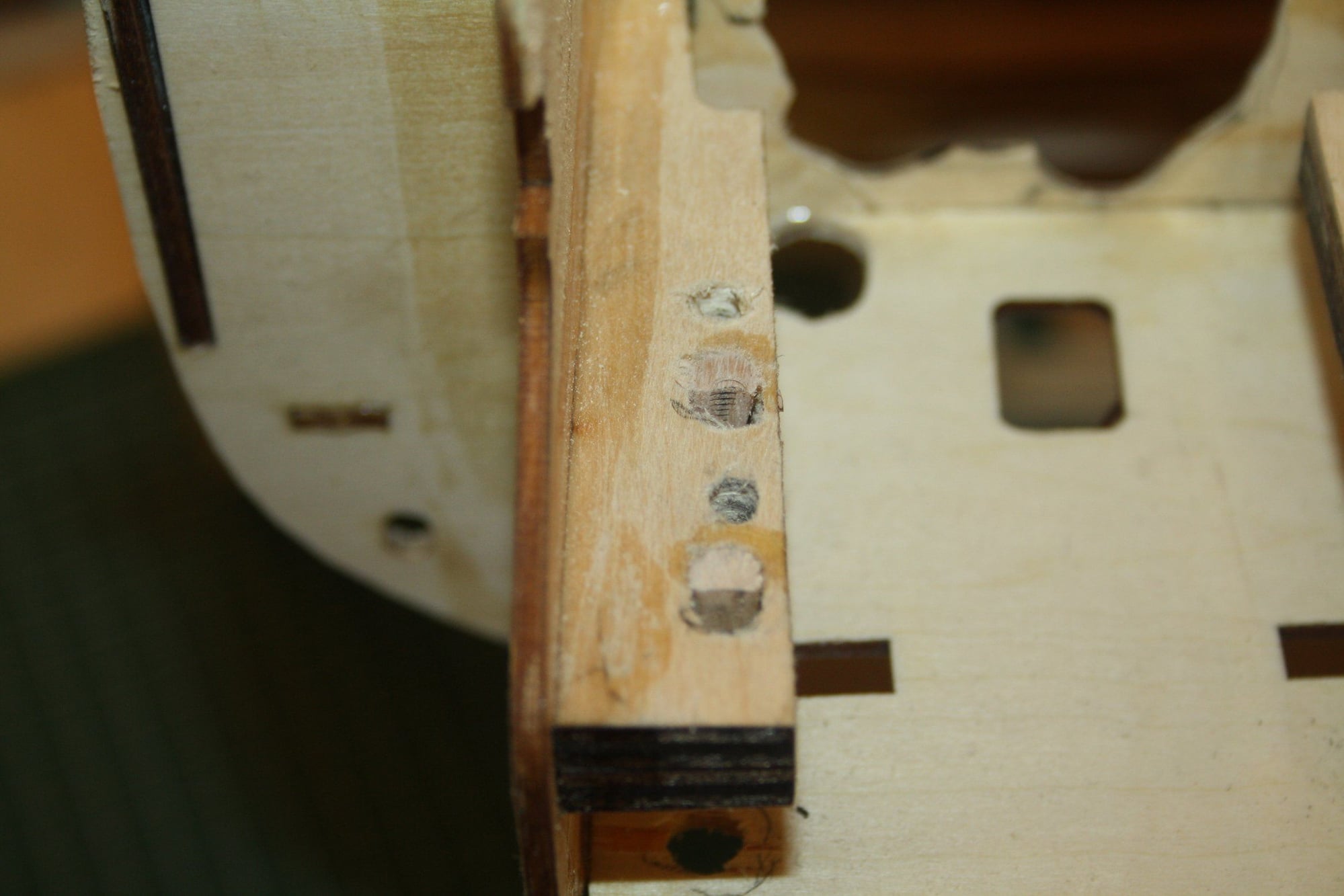
This was not the end of the engine installation nightmare. Once installed I realised that it is mounted with left thrust. I had to modify the holes once more to achieve right thrust. Time will tell if I got it right.
Cheers,
Eran
Cheers,
Eran