Moustache 20cc DHC-2 Beaver Build
 06-22-2022, 03:44 AM
#1

Thread Starter
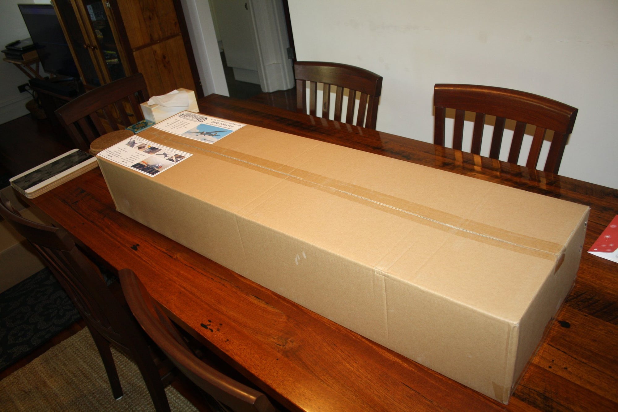
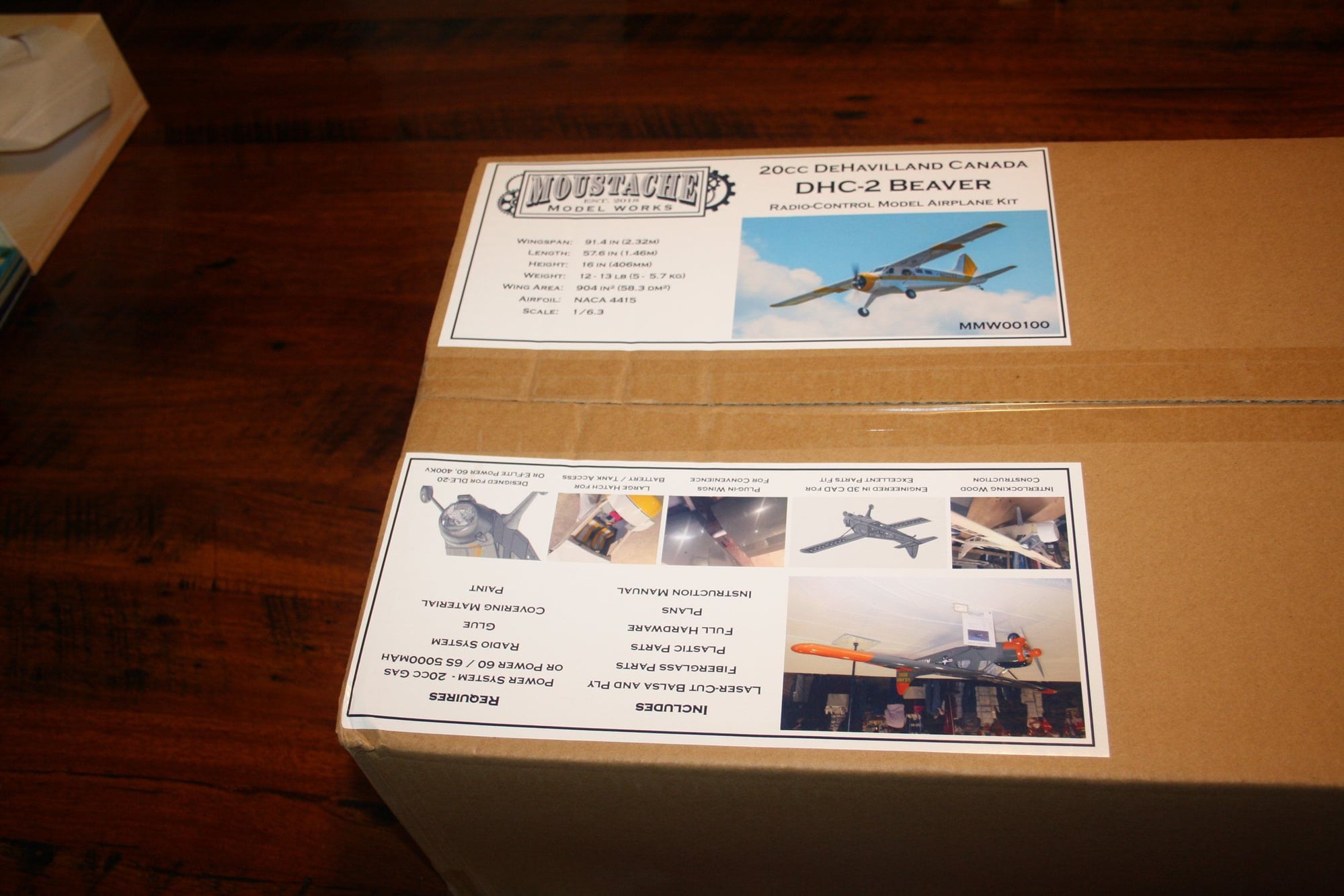
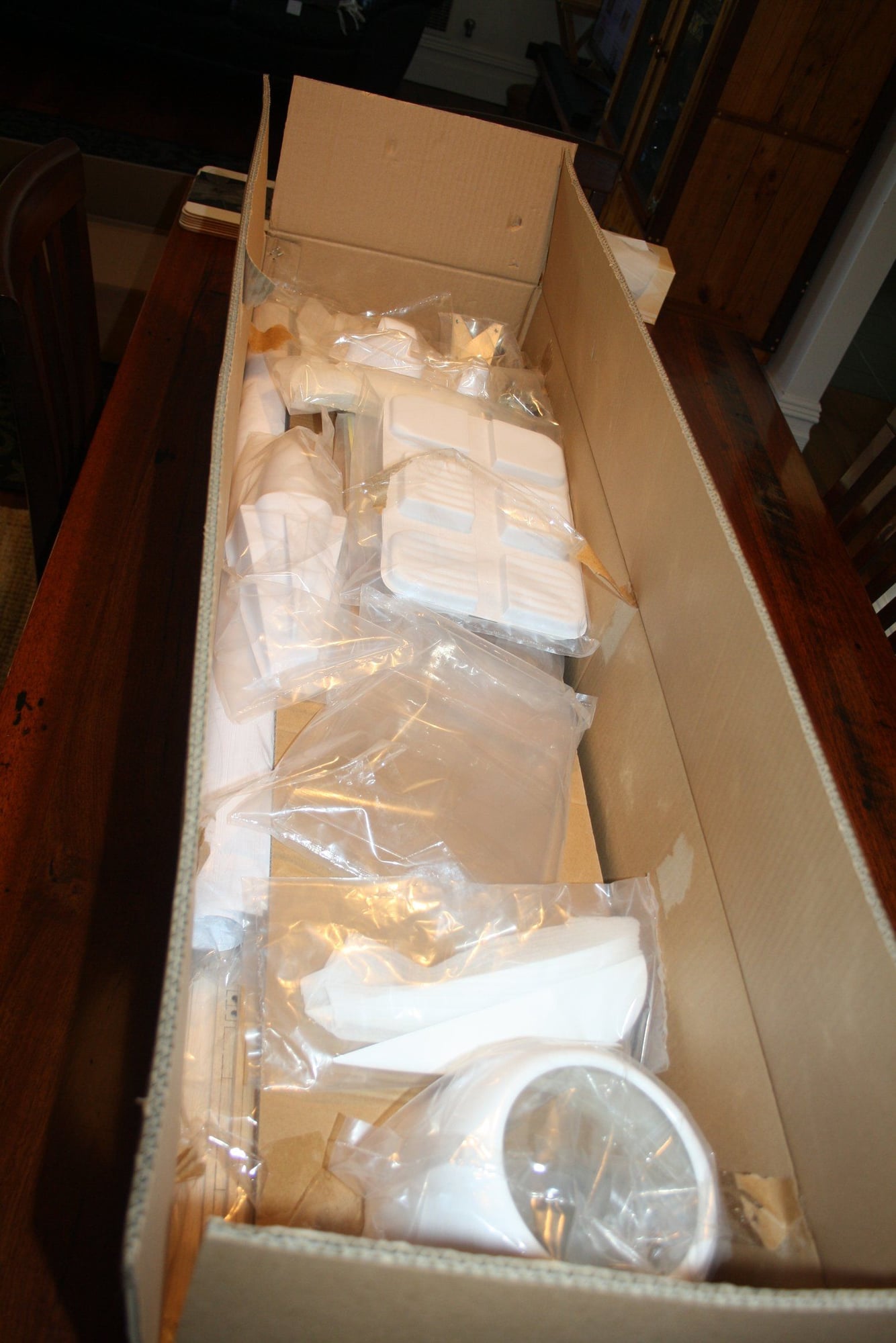
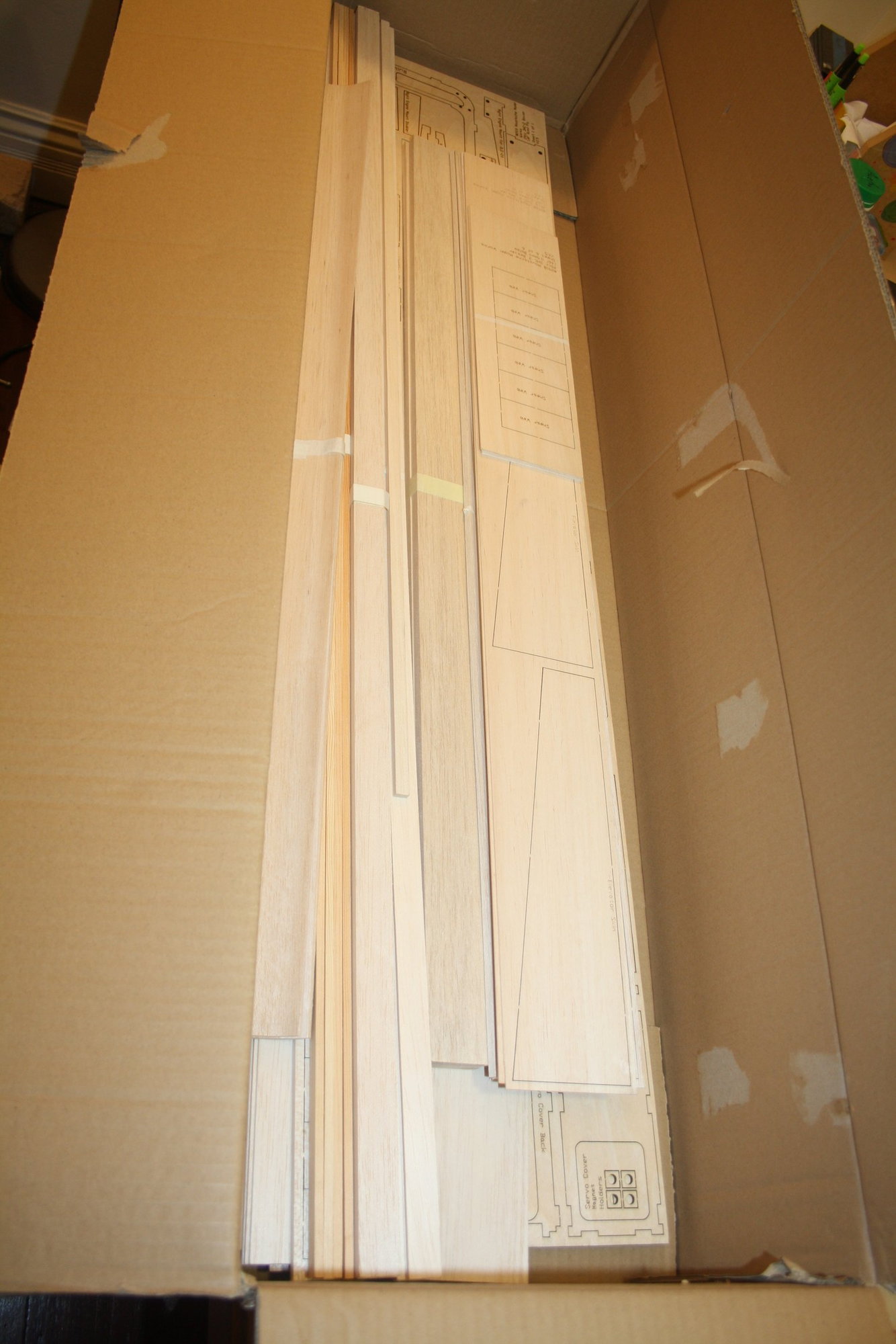
In January 2021, after a over 6 months shipment delays, I received my highly anticipated Moustache Model Works 20cc DeHavilland Canada DHC-2 Beaver kit.
https://www.moustachemodelworks.com/...e/dhc-2-beaver
Some information on the kit is also available in this link:
New 20cc DHC-2 Beaver
For me, it was mostly about the desire to explore what is now possible when a kit is design using modern 3D design software such as the Fusion 360 (which I am playing with myself). It has taken me quite a while to build due to other commitments, but as I edge slowly to completion I decided to share my thoughts and experience so far.
I do not claim to be an "expert" builder. I do have many years of experience and few of my build projects are featured in rcuniverse. My expectation from a kit is that it will be leading the builder to successfully complete the build as designed with minimum amount of problems due to poor instructions, building materials, plans or proposed building techniques.
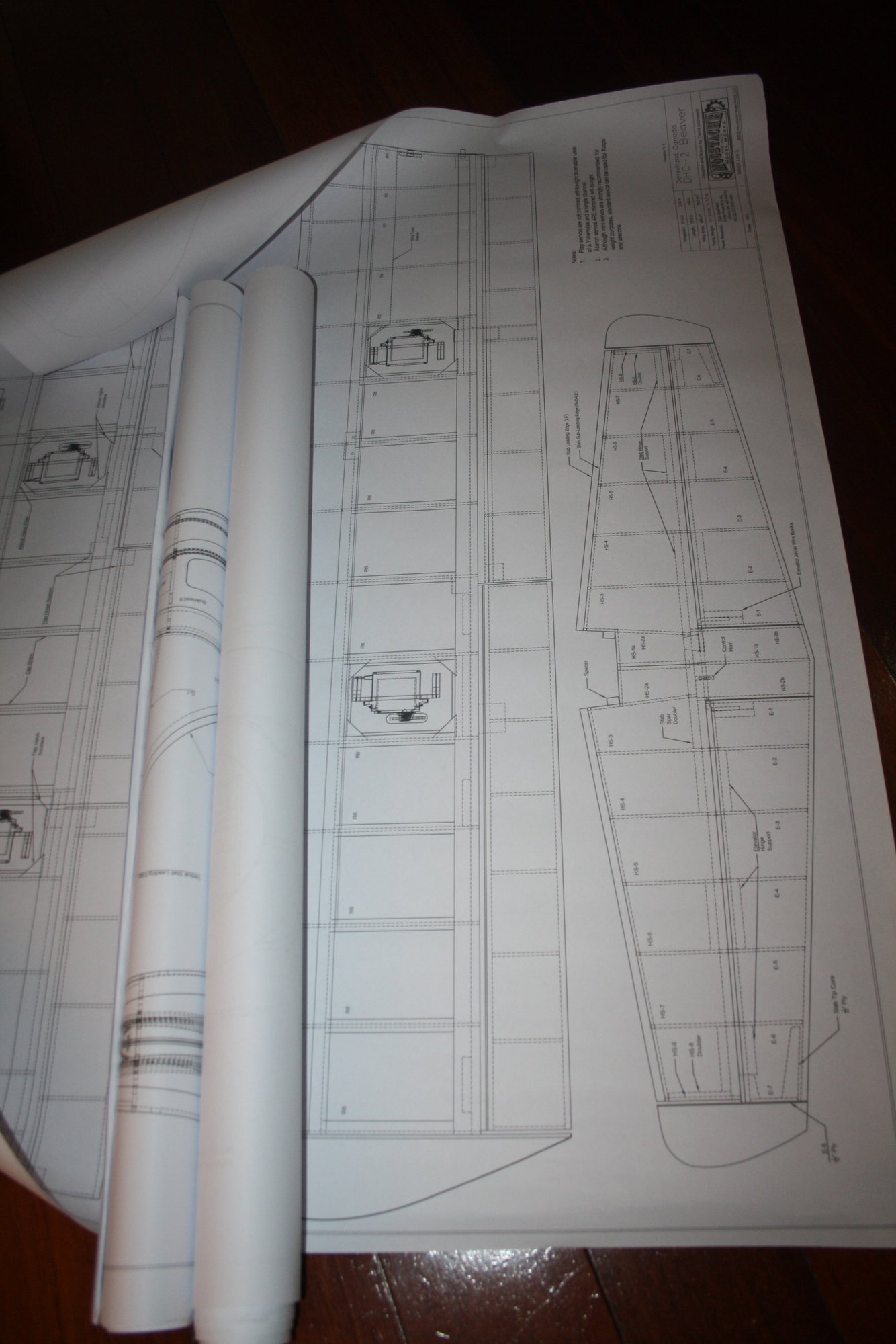
The kit arrived without any damage. Upon inspecting the plans it became obvious that the plans, which seems to be produced by the Fusion 360, were not up to the quality of plans accompanying "traditional" kits, with lack of details and lines overload in some sections. This was compounded by instruction manual in black and white with tiny pictures. A PDF manual was available to download and is much better than the printed version, however, the photos are still not as good quality as they could be.
Cheers,
Eran
https://www.moustachemodelworks.com/...e/dhc-2-beaver
Some information on the kit is also available in this link:
New 20cc DHC-2 Beaver
For me, it was mostly about the desire to explore what is now possible when a kit is design using modern 3D design software such as the Fusion 360 (which I am playing with myself). It has taken me quite a while to build due to other commitments, but as I edge slowly to completion I decided to share my thoughts and experience so far.
I do not claim to be an "expert" builder. I do have many years of experience and few of my build projects are featured in rcuniverse. My expectation from a kit is that it will be leading the builder to successfully complete the build as designed with minimum amount of problems due to poor instructions, building materials, plans or proposed building techniques.
The kit arrived without any damage. Upon inspecting the plans it became obvious that the plans, which seems to be produced by the Fusion 360, were not up to the quality of plans accompanying "traditional" kits, with lack of details and lines overload in some sections. This was compounded by instruction manual in black and white with tiny pictures. A PDF manual was available to download and is much better than the printed version, however, the photos are still not as good quality as they could be.
Cheers,
Eran
 06-22-2022, 04:12 AM
#2
Thread Starter
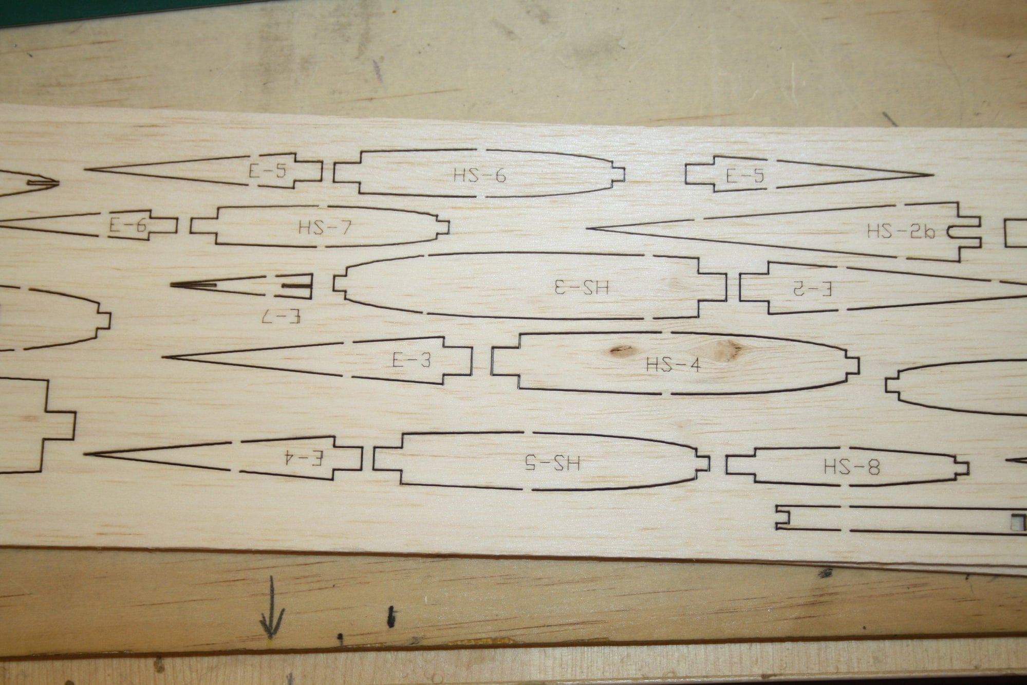
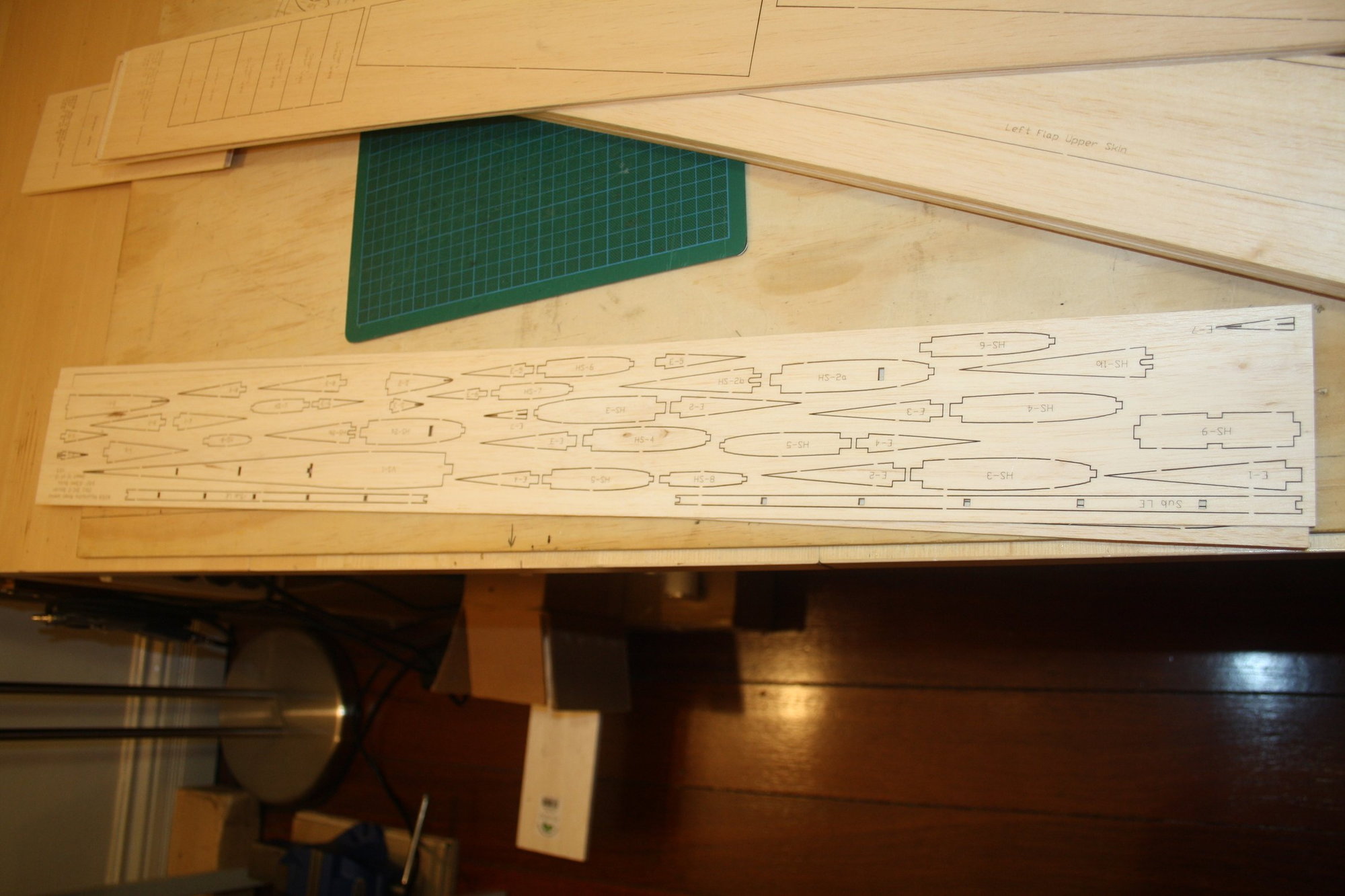
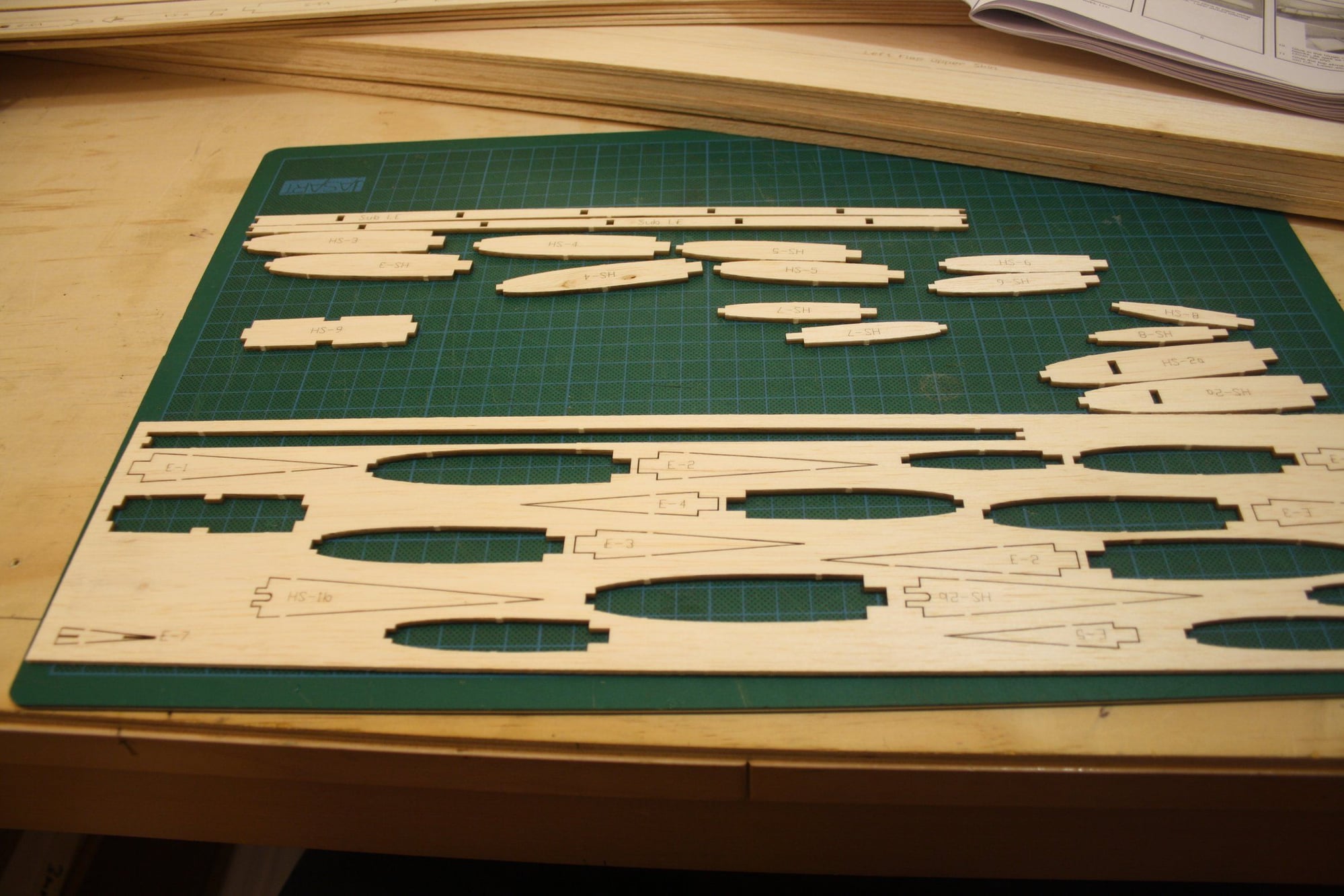
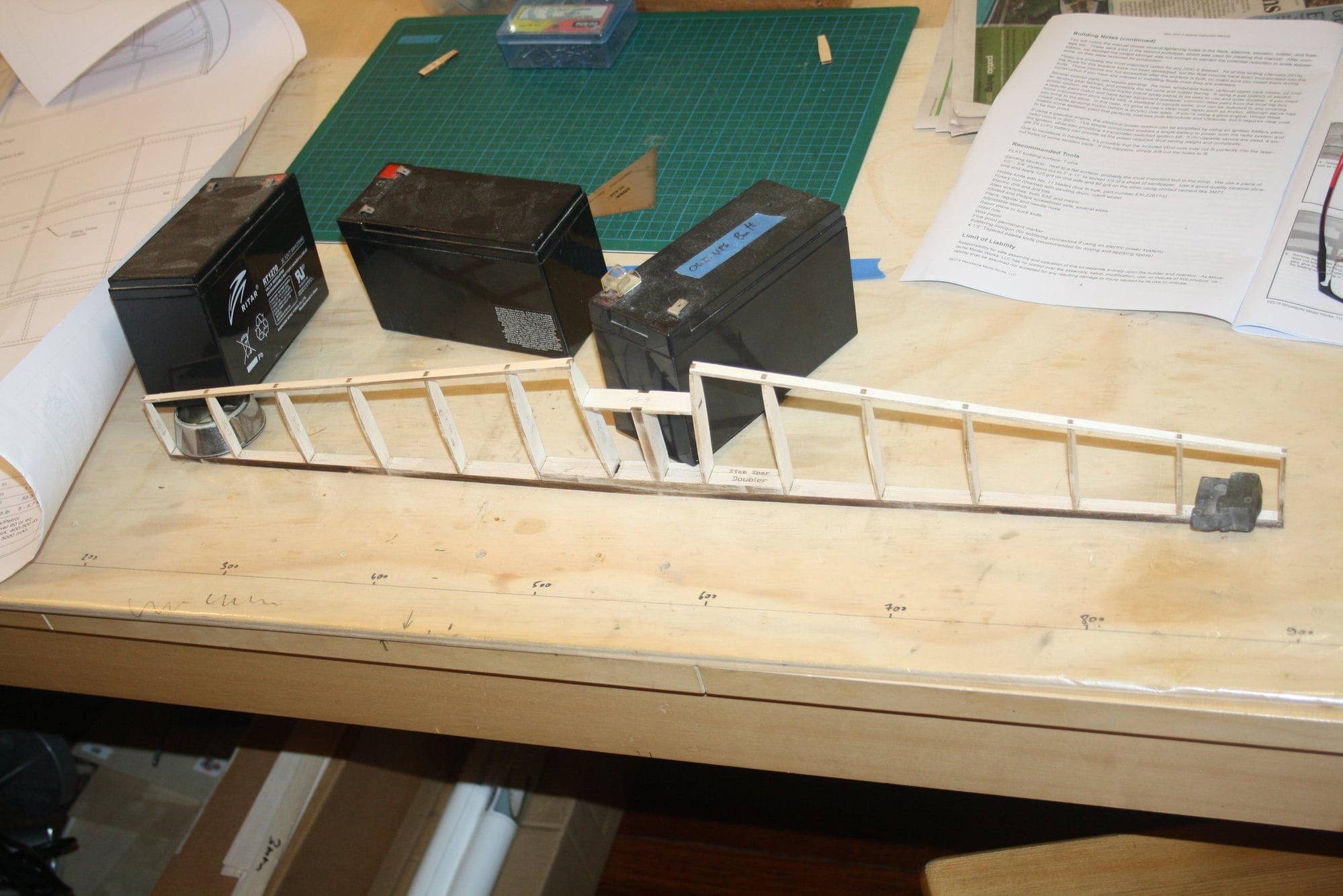
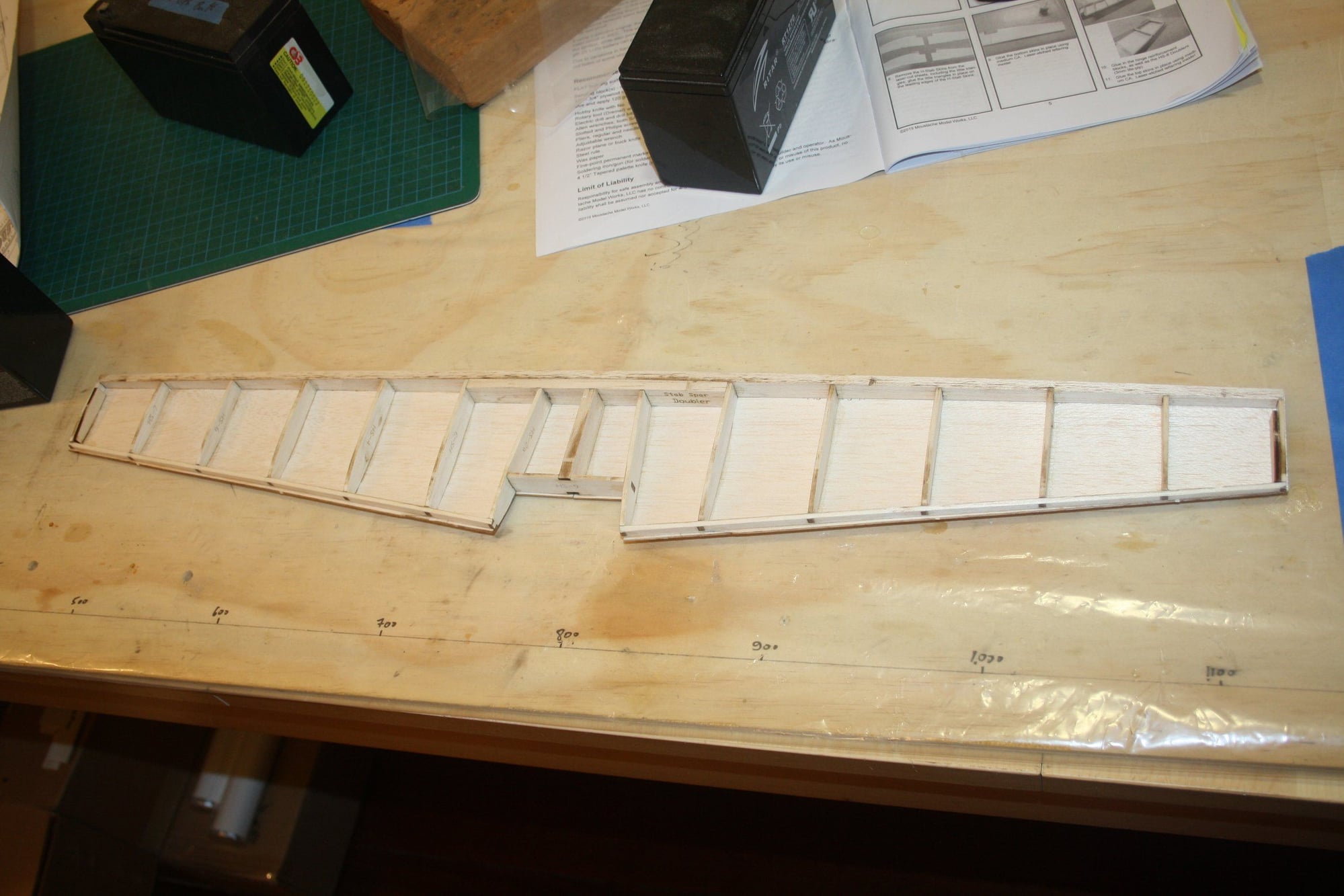
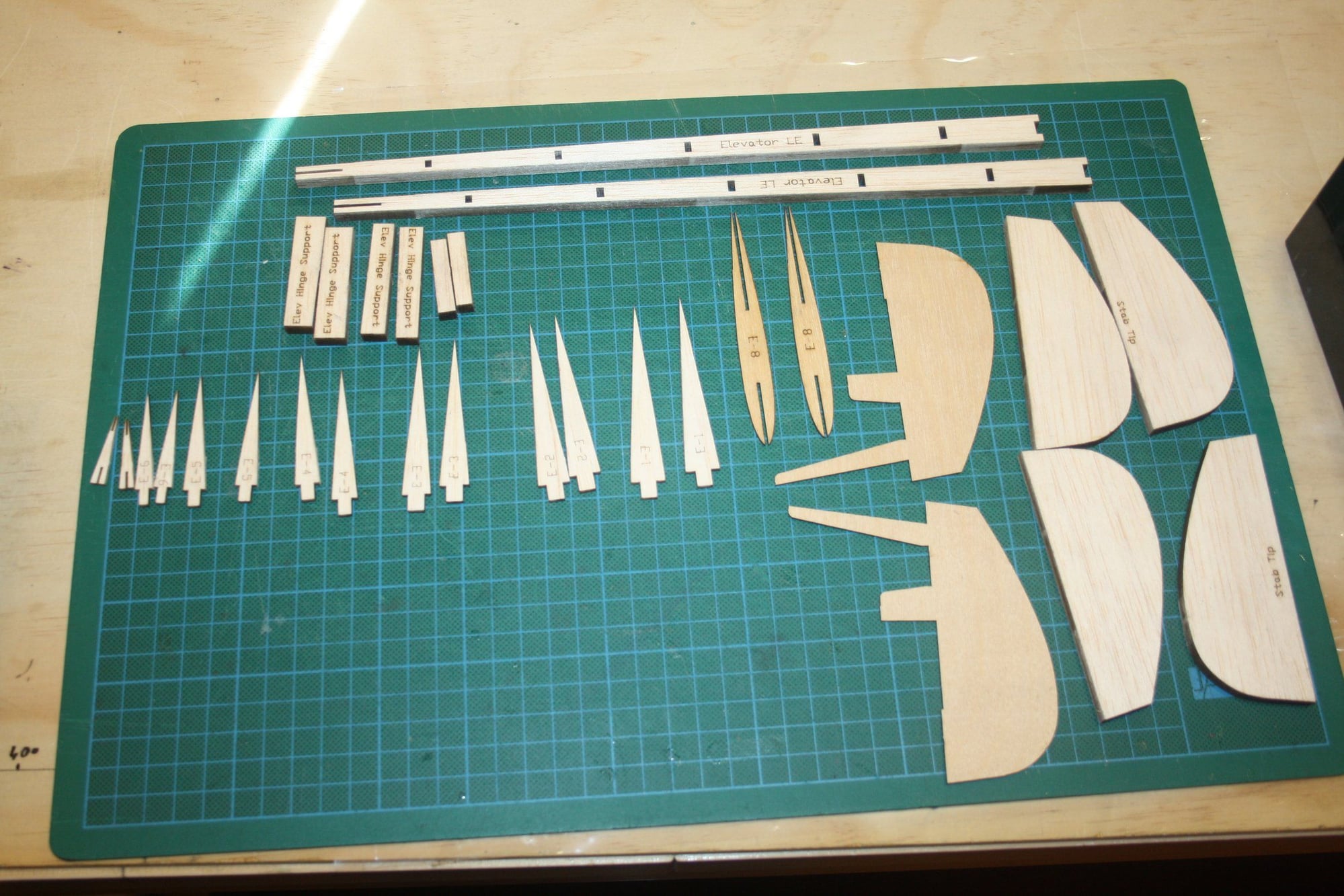
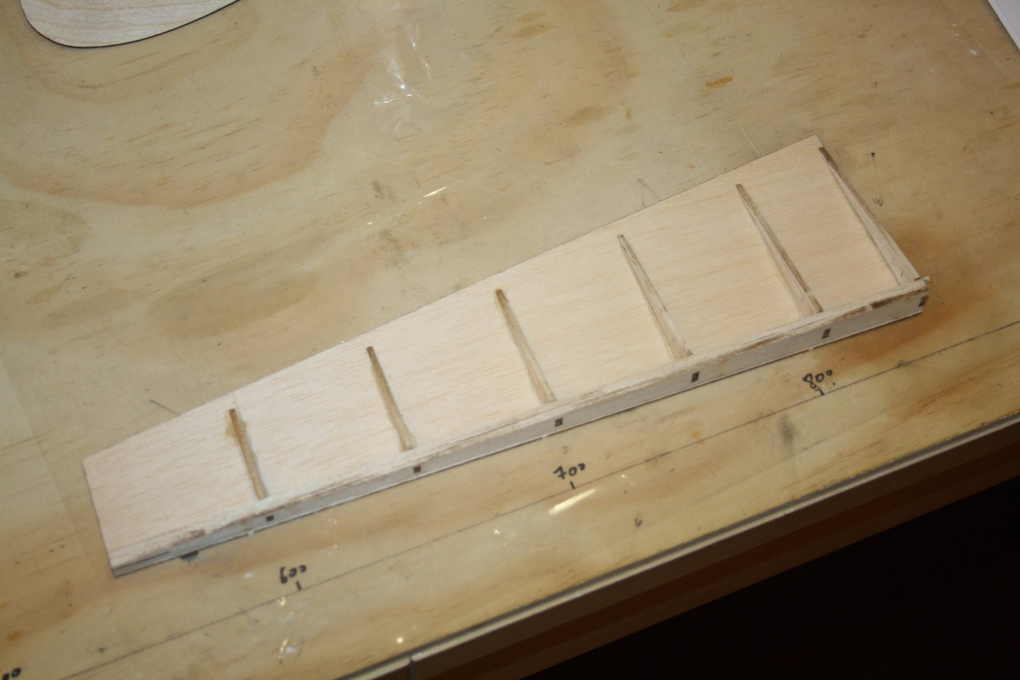
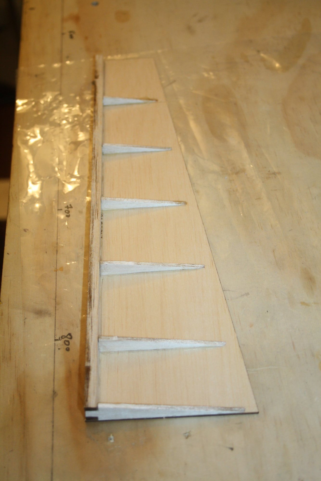
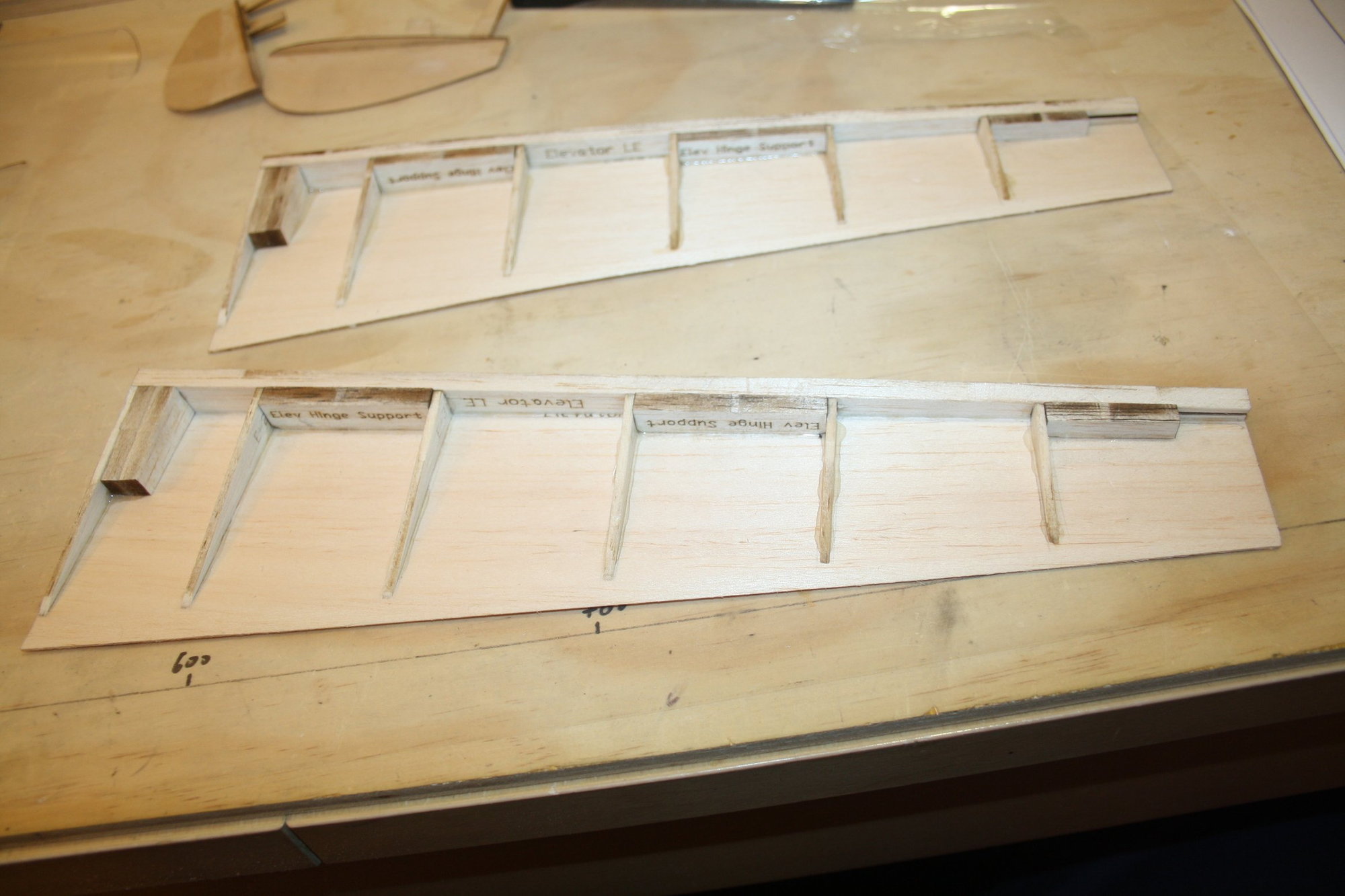
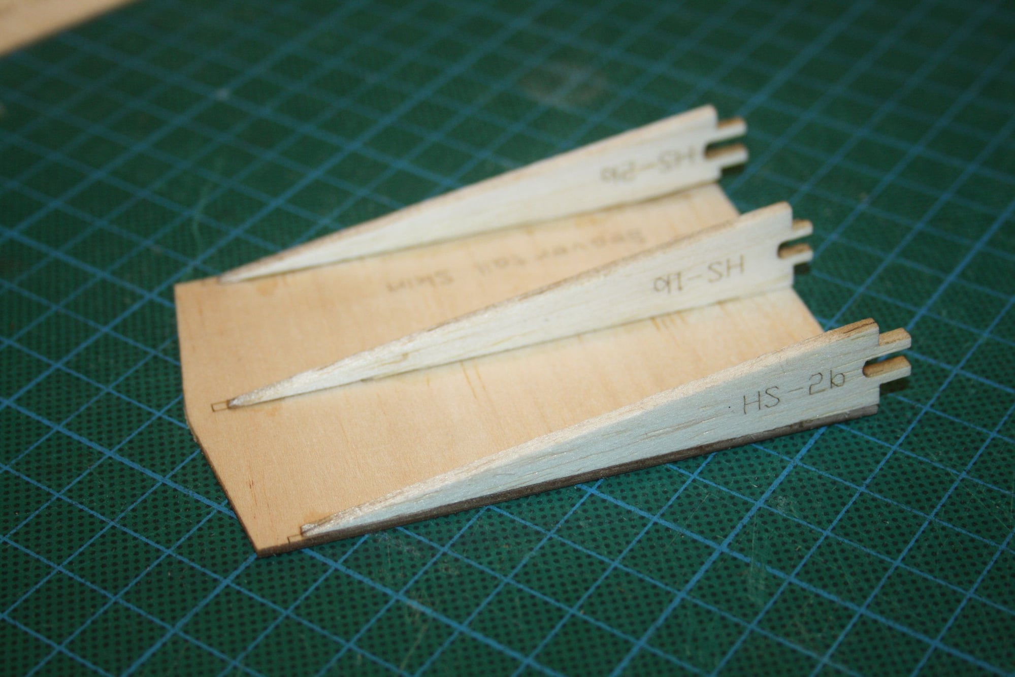
Following the instruction manual, I started the build with the horizontal stabiliser. The laser cutting was good and the construction progressed quickly. However, one issue that became obvious and was presenting itself throughout this build was the lack of some aspects of engineering consideration in the design, in this case, the lack off allowance for clearances. Do not get me wrong, by using the 3D design some of the engineering achievements within this kit were impressive, however where issues were found it was disappointing considering that all were easily avoidable.
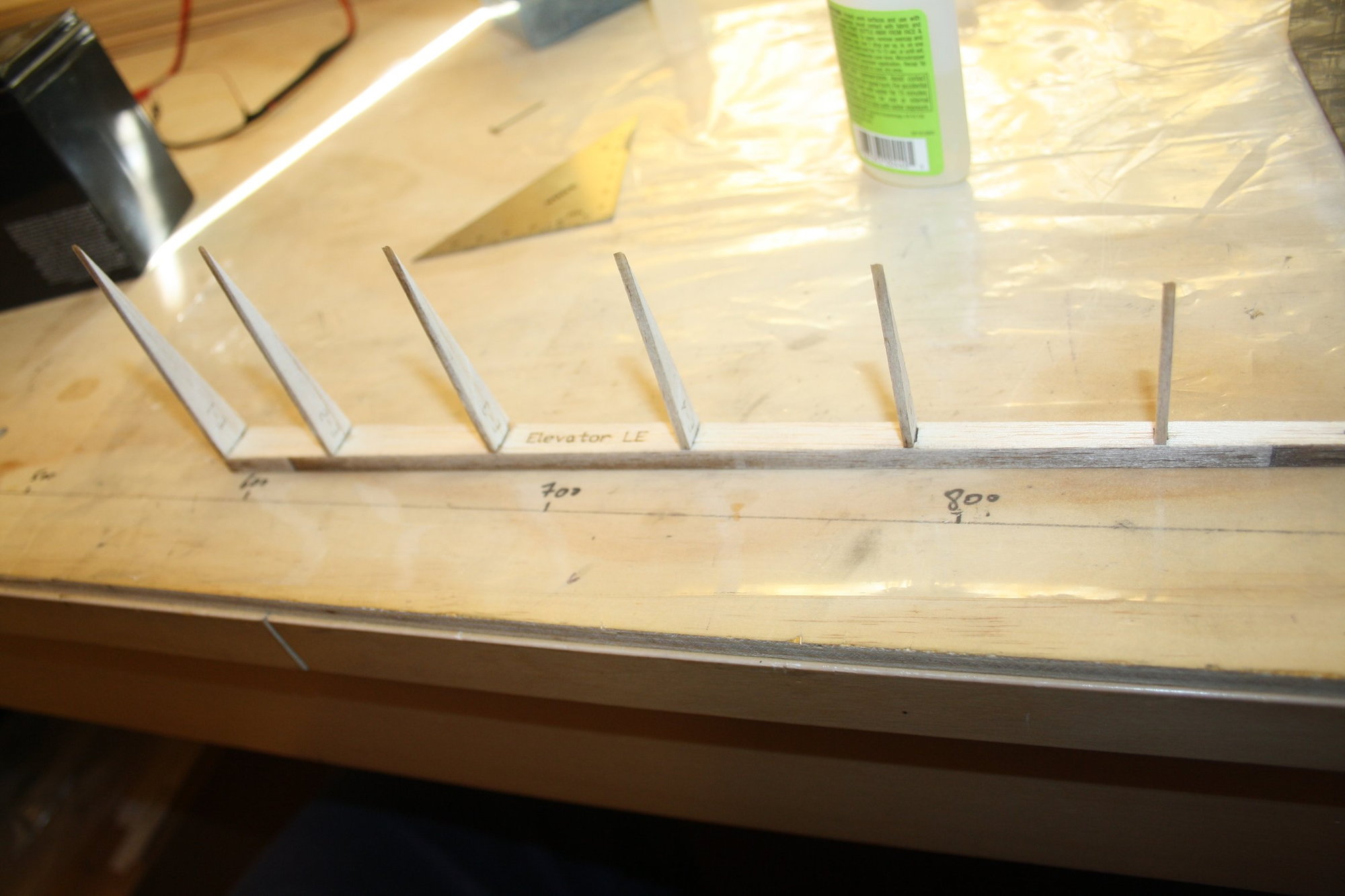
It seems that the design assumed perfect material thickness with no variability and as a result, the airfoils tabs were too long for the thickness of the trailing edge. Since this part is built vertically, the long tabs prevented the airfoil from sitting "all the way in" and all of the airfoils required shortening the tabs to fit properly.
Cheers,
Eran
06-22-2022, 11:14 AM
#3

Having also worked with Fusion 360, it seems to me that "all of the tabs were too long" was for a reason that may not be apparent at the point you are. I hope you didn't create a problem for you with the ailerons and flaps.
06-22-2022, 08:31 PM
#4
Beautiful airplane, it does not build like an old style kit, but it does go together nicely. the only issue I had with the build was getting the vertical fin straight, I had to cut one side loose and re align it after my first try had a twist in it. take your time and it should come out straight. The only issue I had with the kit was the hardware, (and I did not contact the manufacturer about this as it was just easier to replace) the threaded rods were bad and I had clevises strip, one had concentric cuts instead of threads, I had hinges break in flight, both door, flap and aileron. I even had 3 of the 4 motor mount bolts break at an odd place during flight. the plane flies great and since replacing the hardware pieces I think that I have got most of the bugs out. I built the struts but they would come loose in flight and I didn't want to re engineer them so I just left them off. I also removed the gear fairings and stiffened up the gear after fixing them 3 or 4 times.

New years day fun fly 2021
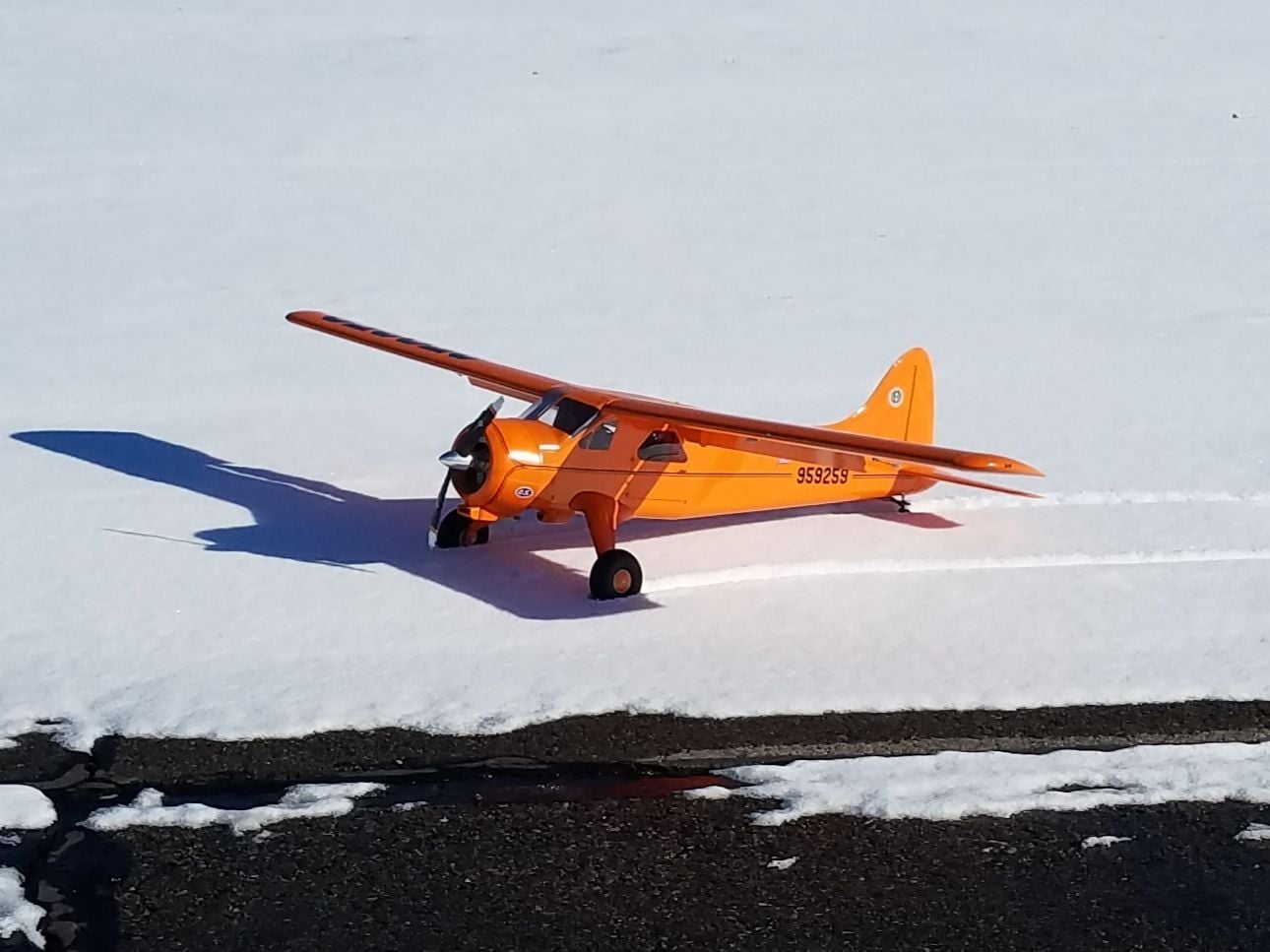
OS 22cc engine, more than enough power at 5000ft altitude
modified bracing and bungees on main gear, this helps me land without the plane bouncing back into the air.
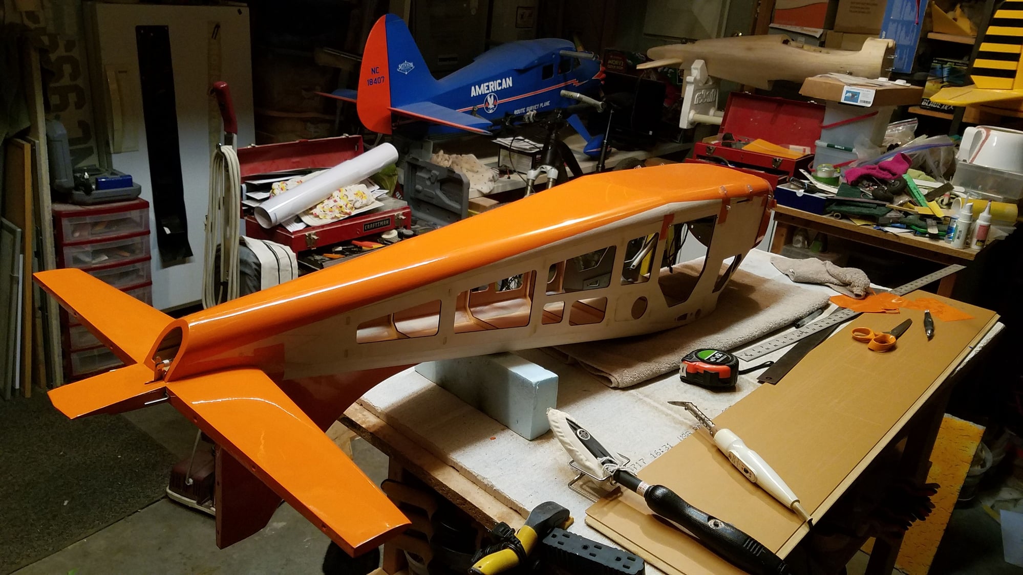
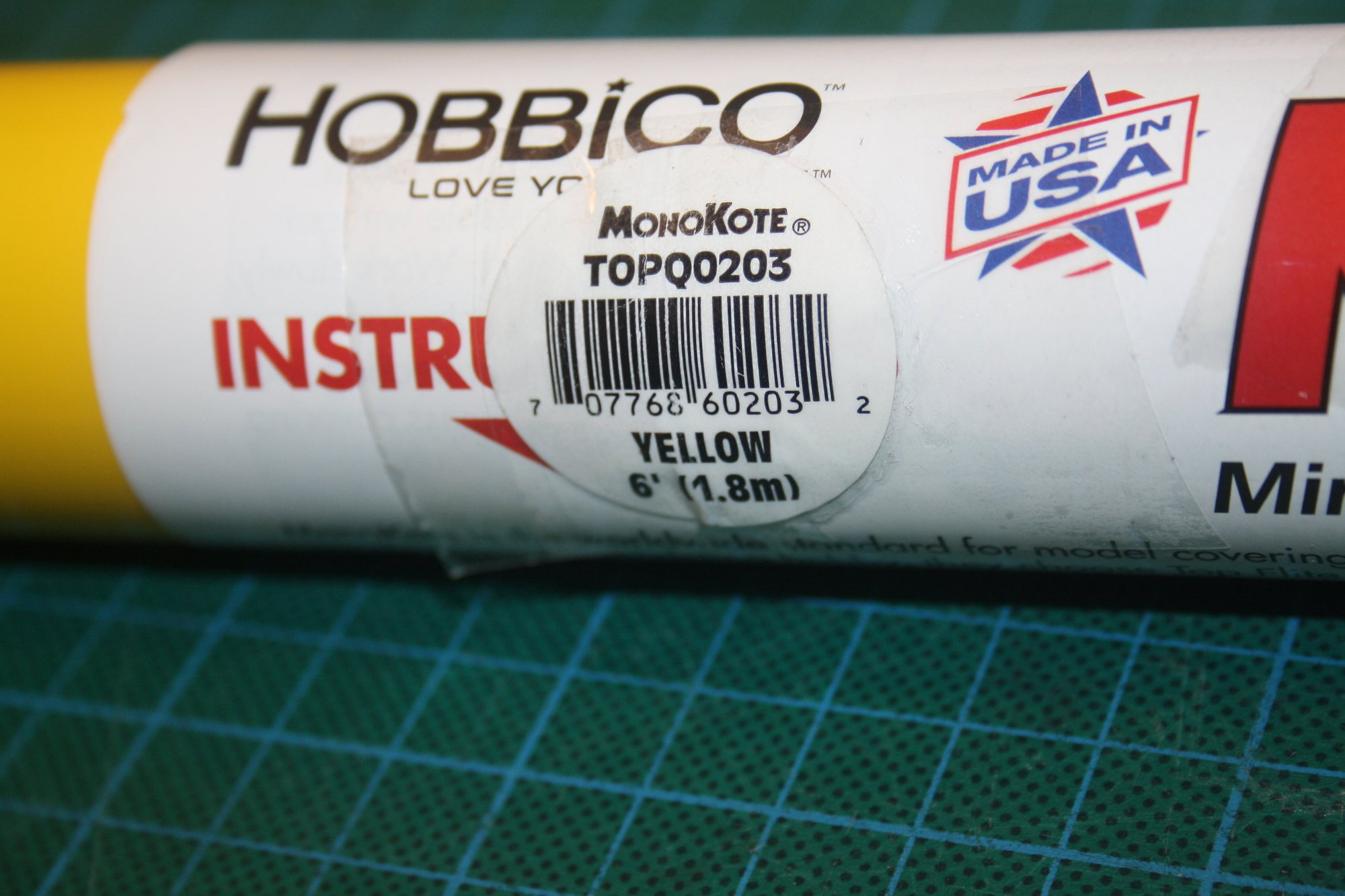
Take your time with the covering and it will look gorgeous, I used Monokote to get the shade of orange that I wanted. I started doing the 1950s trans Antarctic color scheme, but decided that I didn't want to put in the effort on the decals
trimming around the fittings helped the covering look good. It took me 1 evening to do each side of the fuselage in 1 piece to eliminate seams
New years day fun fly 2021
OS 22cc engine, more than enough power at 5000ft altitude
modified bracing and bungees on main gear, this helps me land without the plane bouncing back into the air.
Take your time with the covering and it will look gorgeous, I used Monokote to get the shade of orange that I wanted. I started doing the 1950s trans Antarctic color scheme, but decided that I didn't want to put in the effort on the decals
trimming around the fittings helped the covering look good. It took me 1 evening to do each side of the fuselage in 1 piece to eliminate seams
06-23-2022, 12:34 AM
#5
Thread Starter
rgburrill - As I mentioned in the first posting, I am in a much advanced stage than the posting itself. I did not encounter any issue due to the sanding. Having the tabs long was unnecessary.
bryanmick - Your Beaver is beautiful. I was about to have my own Beaver done in orange but changed to yellow (doing a loose color scheme representation of A95-201, the Australian Arctic Expedition Beaver). It is rare to get good hardware included in a kit (or ARF) these days. I was not planning on using the supplied hardware and now I am convinced not to. Thank you.
Cheers,
Eran
06-23-2022, 12:51 AM
#6
Thread Starter
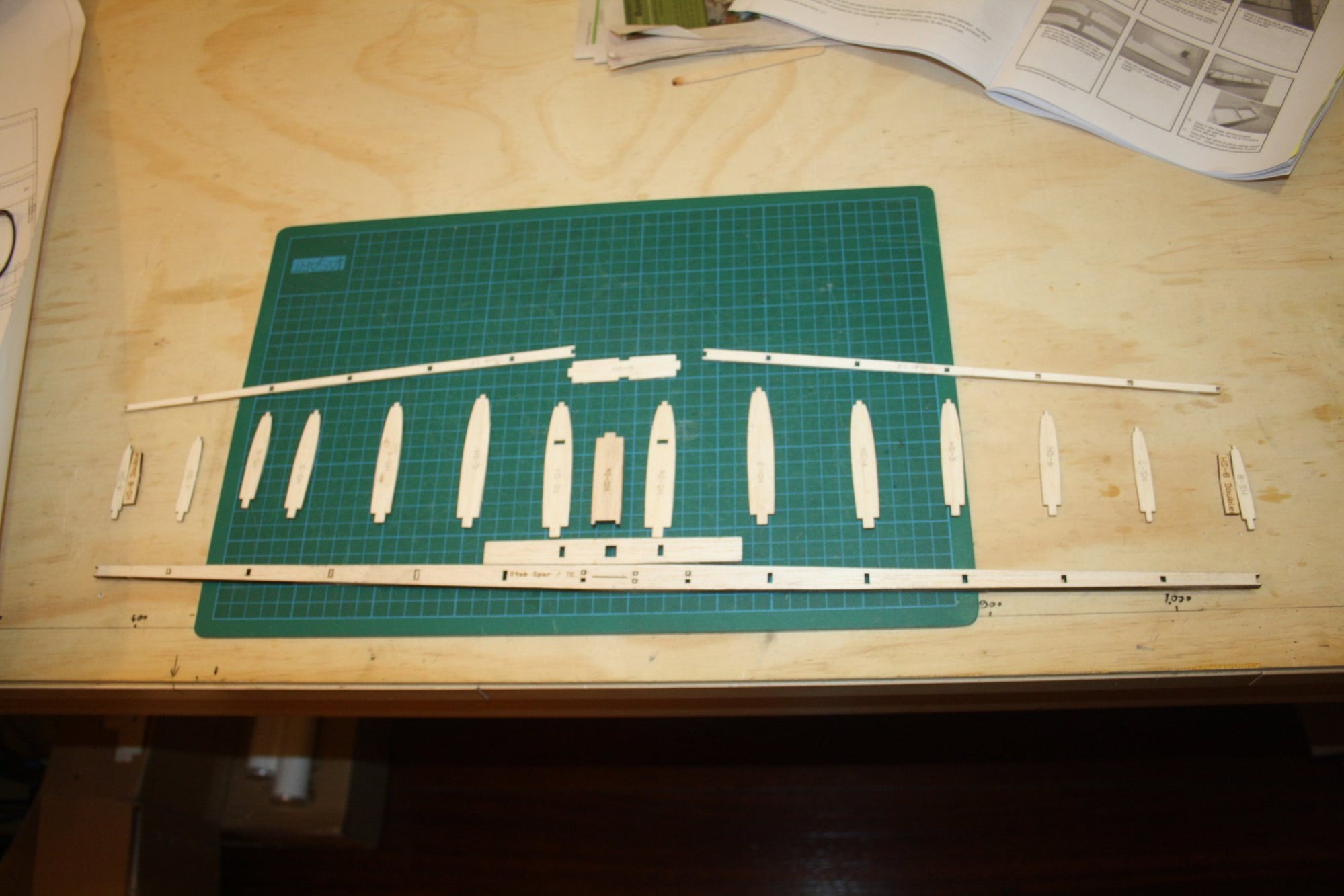
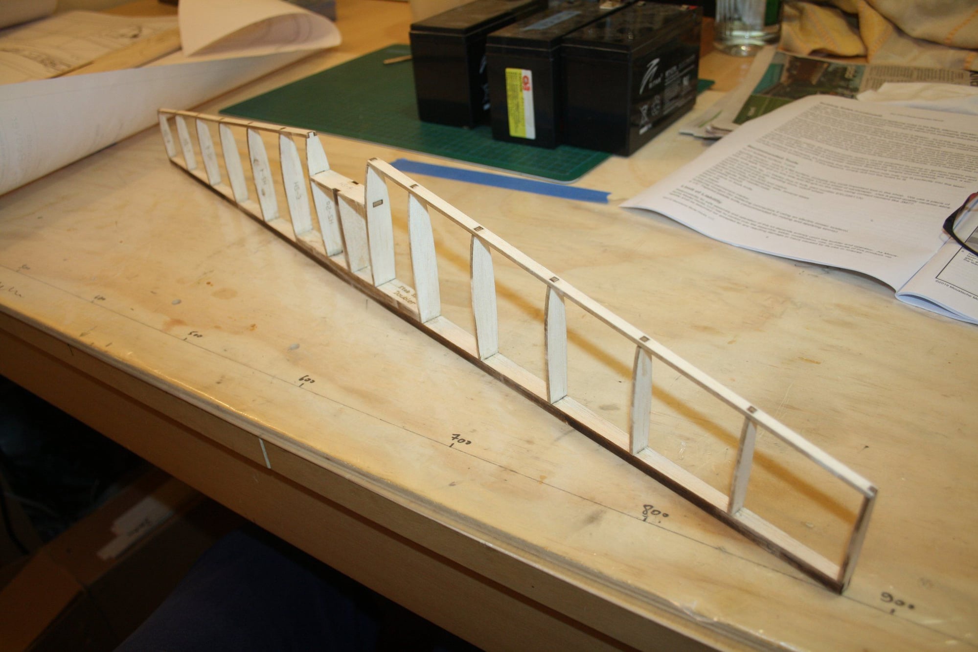
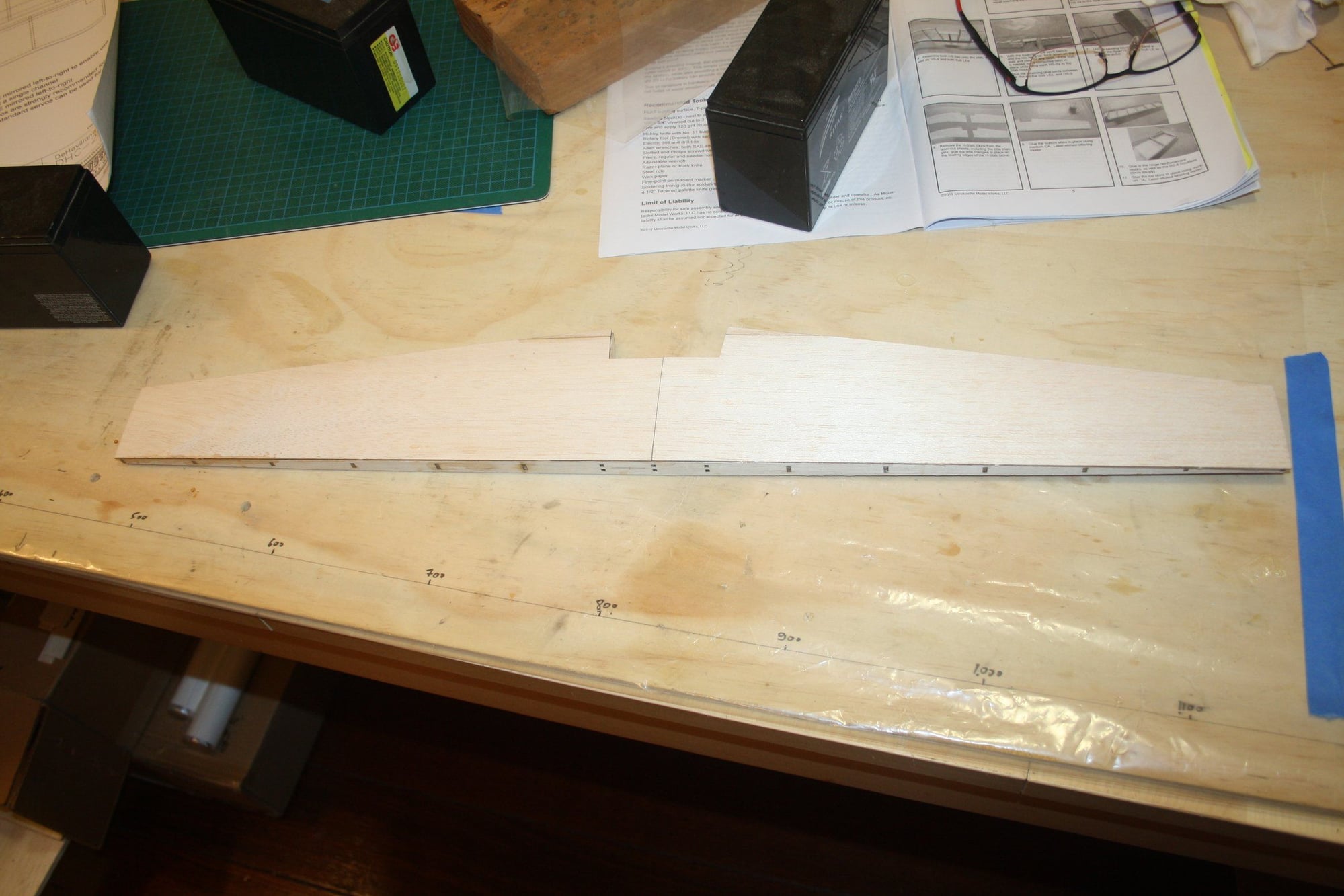
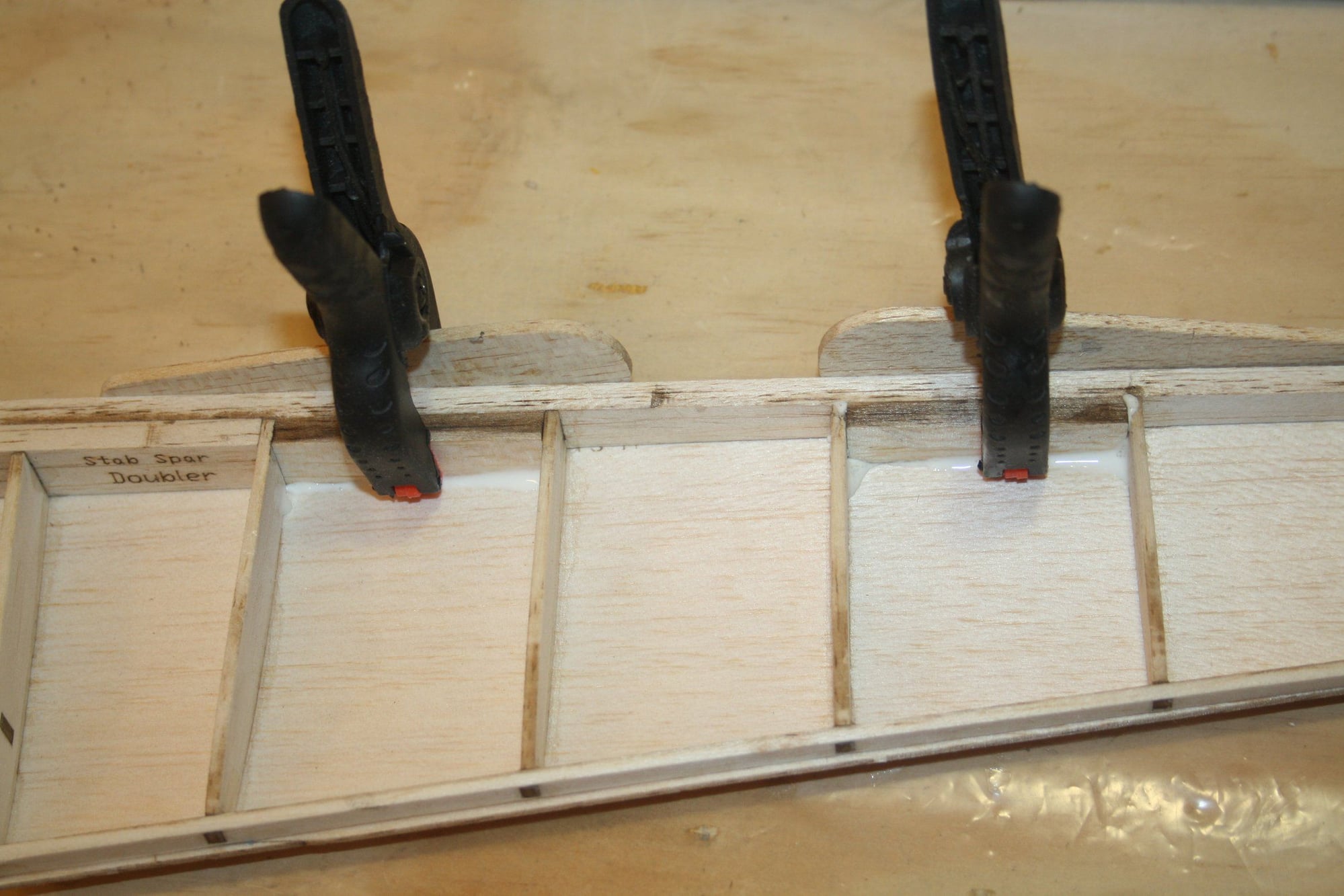
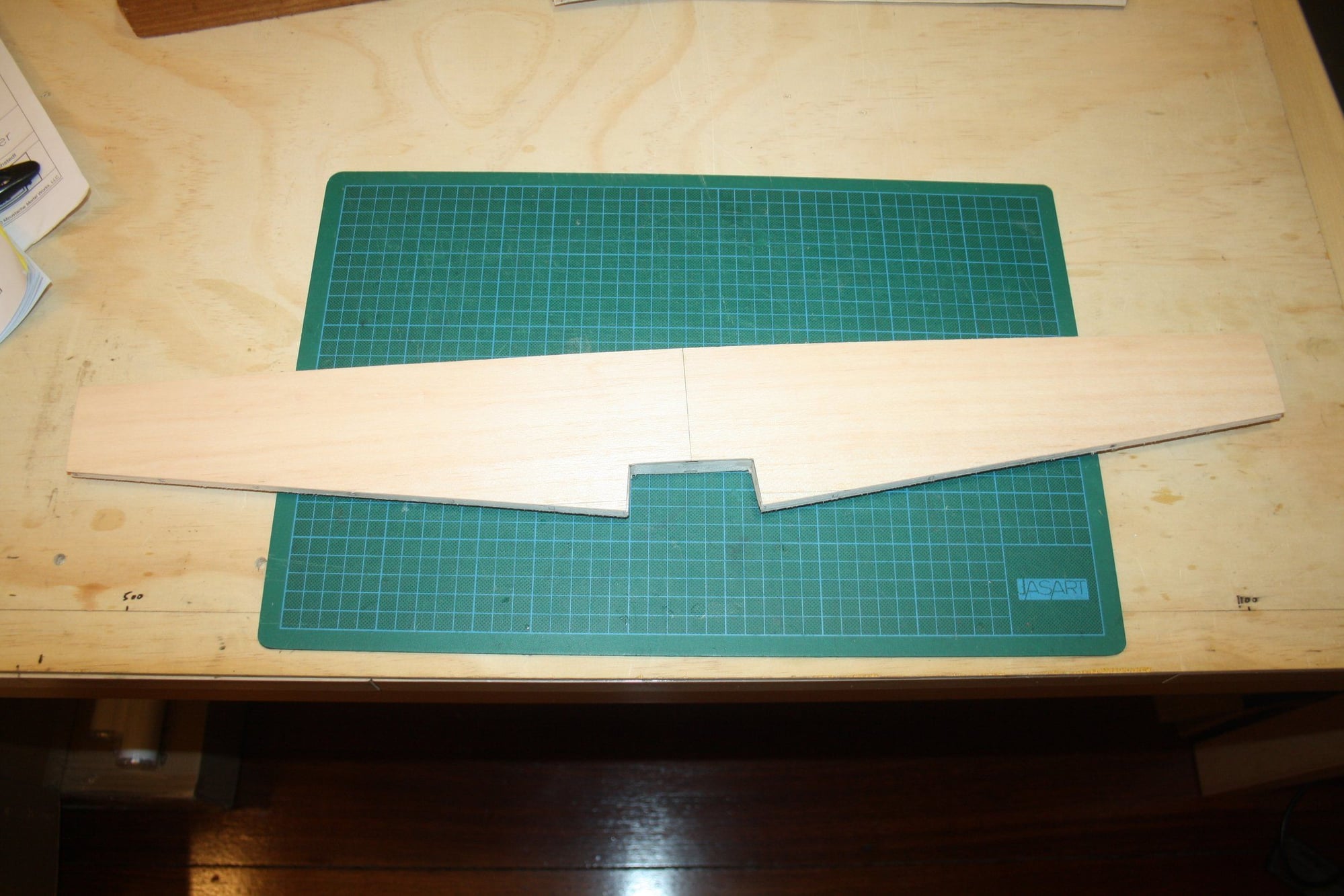
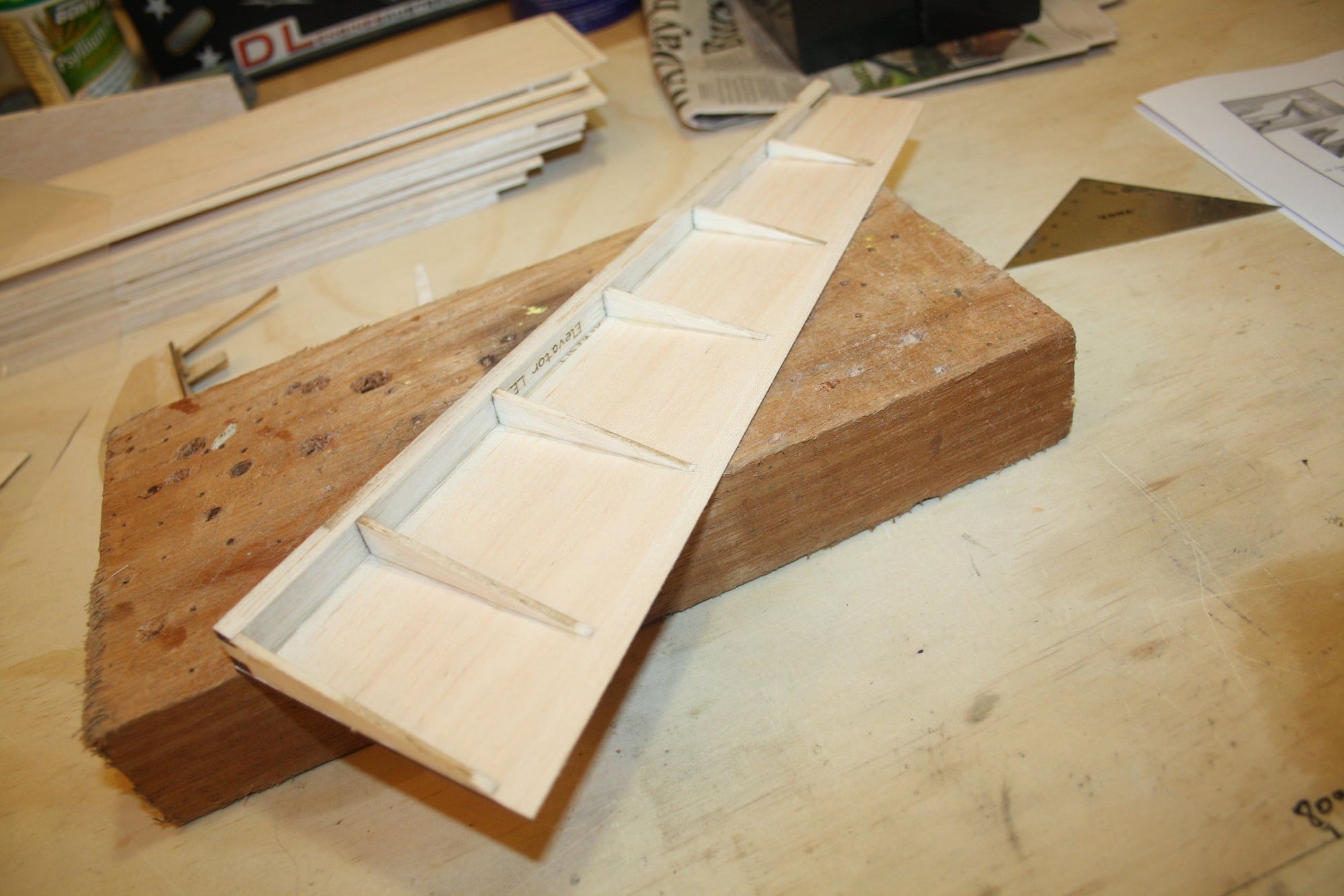
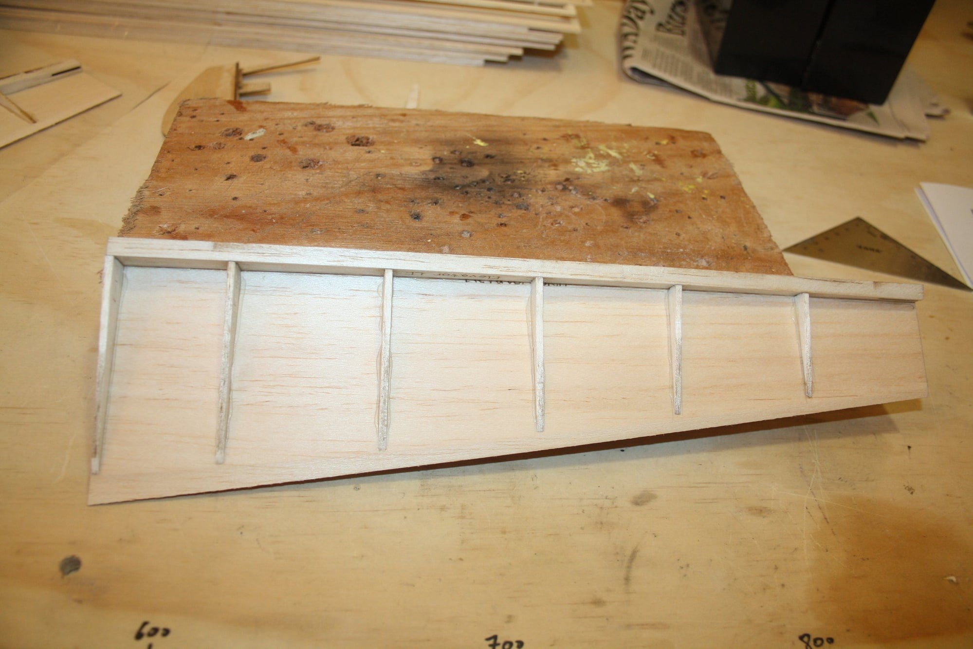
The laser cut sheeting fitted perfectly demonstrating the advantage of 3d design (if you do your bit aligning it correctly...).
The photos also show gluing the hinge reinforcement to the TE.

Cheers,
Eran
The photos also show gluing the hinge reinforcement to the TE.
Cheers,
Eran

 06-24-2022, 10:14 AM
#10
Erans,
I built this kit last year after a bout with Covid finally broke my addiction to ARFs. I encountered few problems during the process as I tried to reactivated skills atrophied over two decades.
The best part was the first flight and the ease with which the model dialed in.
If there's any way you think I can help, please do not hesitate to ask. I'll be following with great interest.
Take care,
Bren Bailey
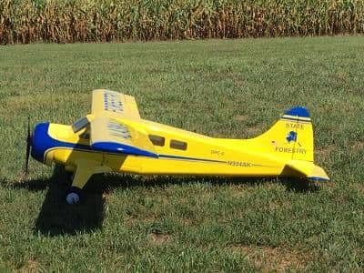
My MMW Beaver after its first flight.
I built this kit last year after a bout with Covid finally broke my addiction to ARFs. I encountered few problems during the process as I tried to reactivated skills atrophied over two decades.
The best part was the first flight and the ease with which the model dialed in.
If there's any way you think I can help, please do not hesitate to ask. I'll be following with great interest.
Take care,
Bren Bailey
My MMW Beaver after its first flight.
06-24-2022, 07:50 PM
#11
Thread Starter
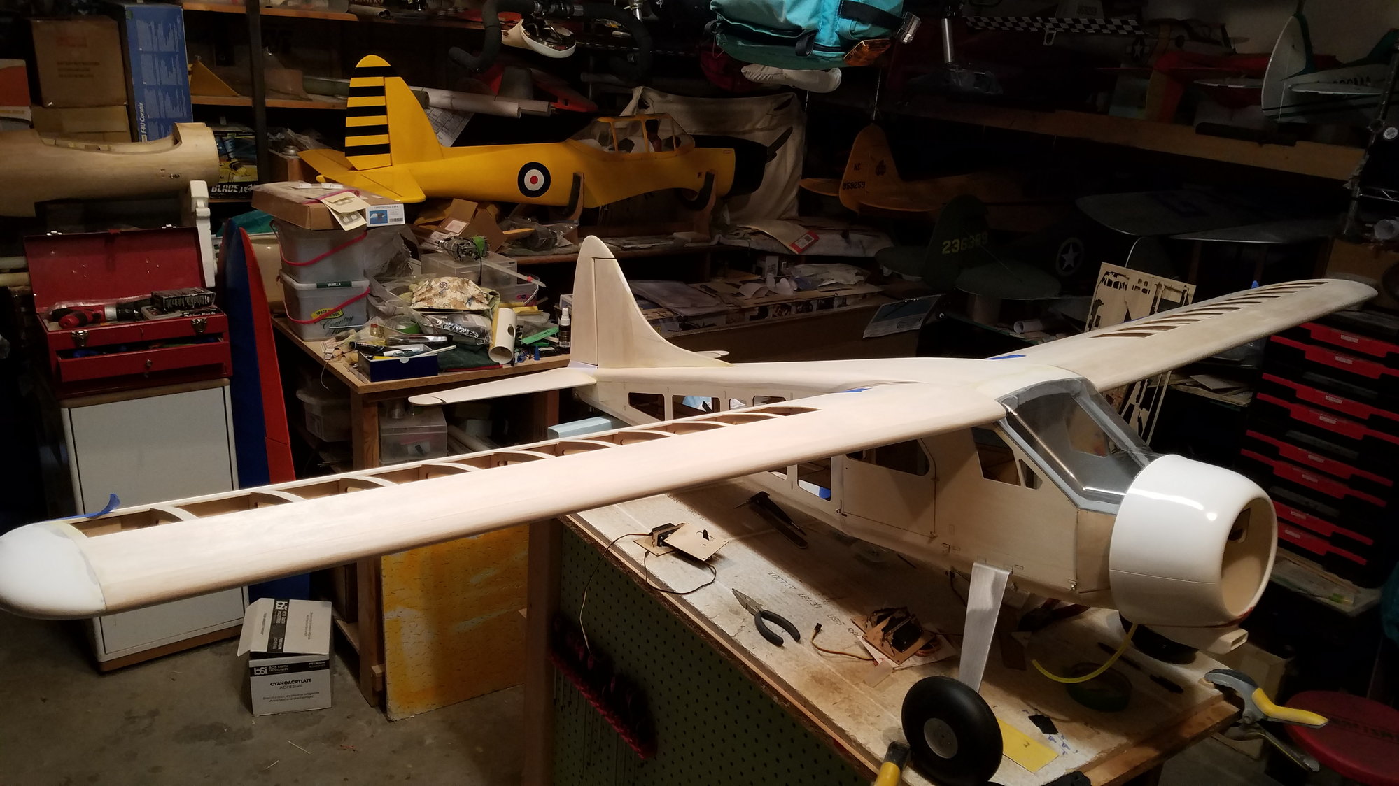
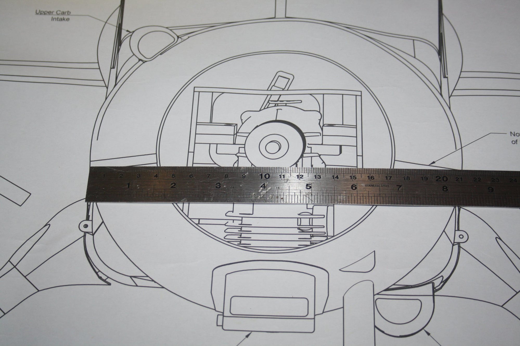
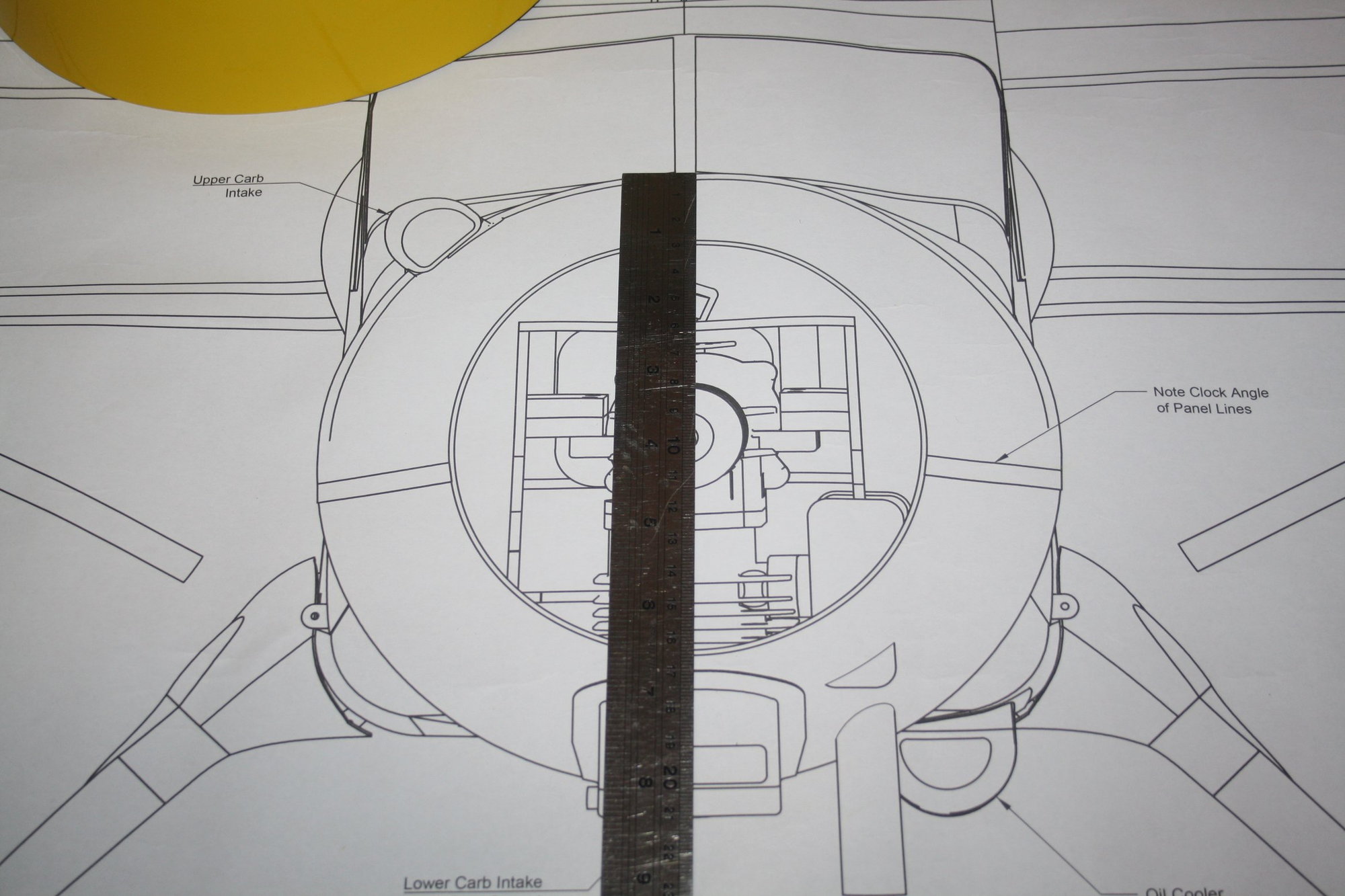
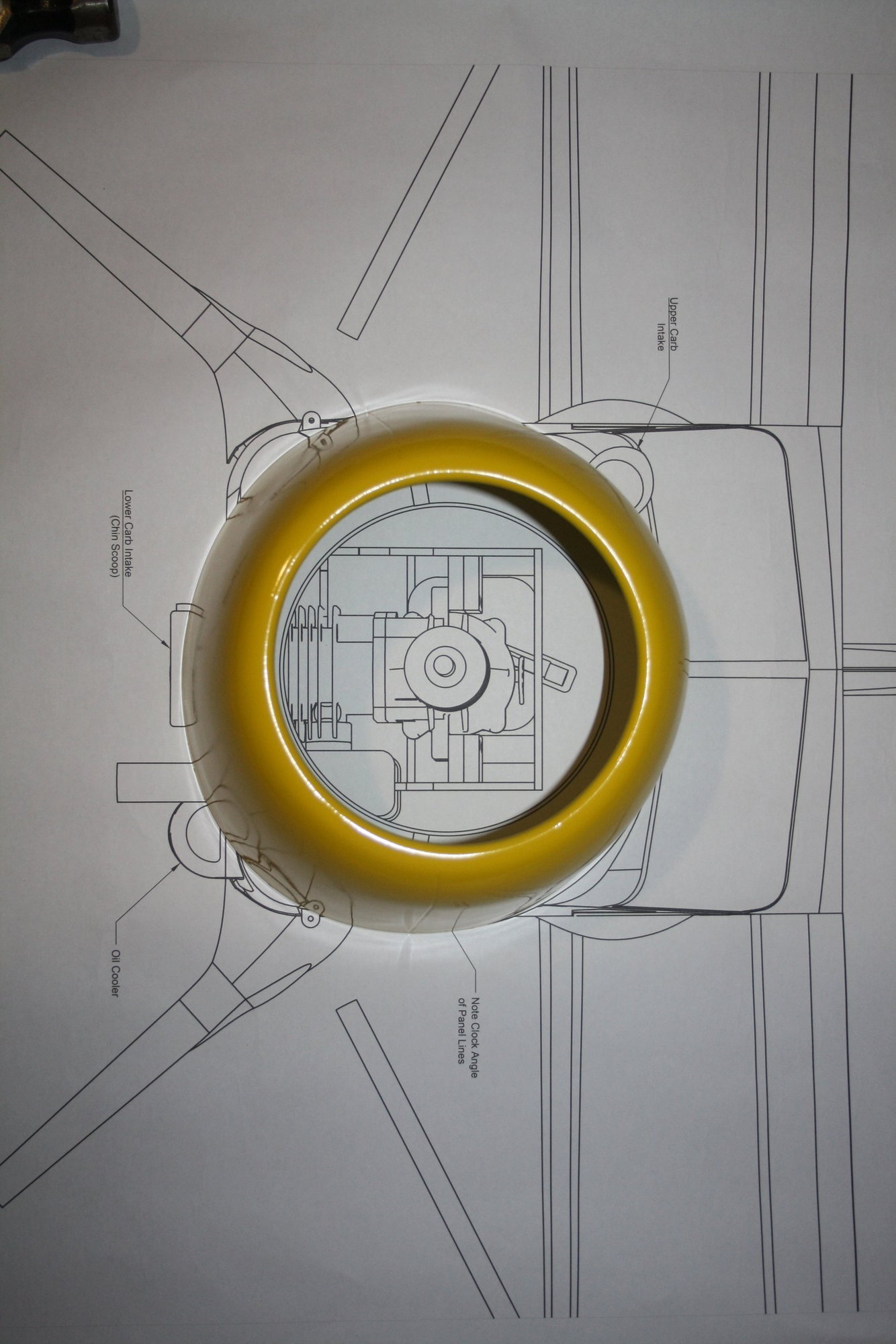
Bren - Another beautiful model of this Beaver. I am currently at the stage of fitting the cowl (hopefully this week), this thread is mostly to show the building process with better photos than the manual. I am receiving comments from forum participants years after posting a photographic build thread mentioning how helpful it was finding detailed photos for build stages.
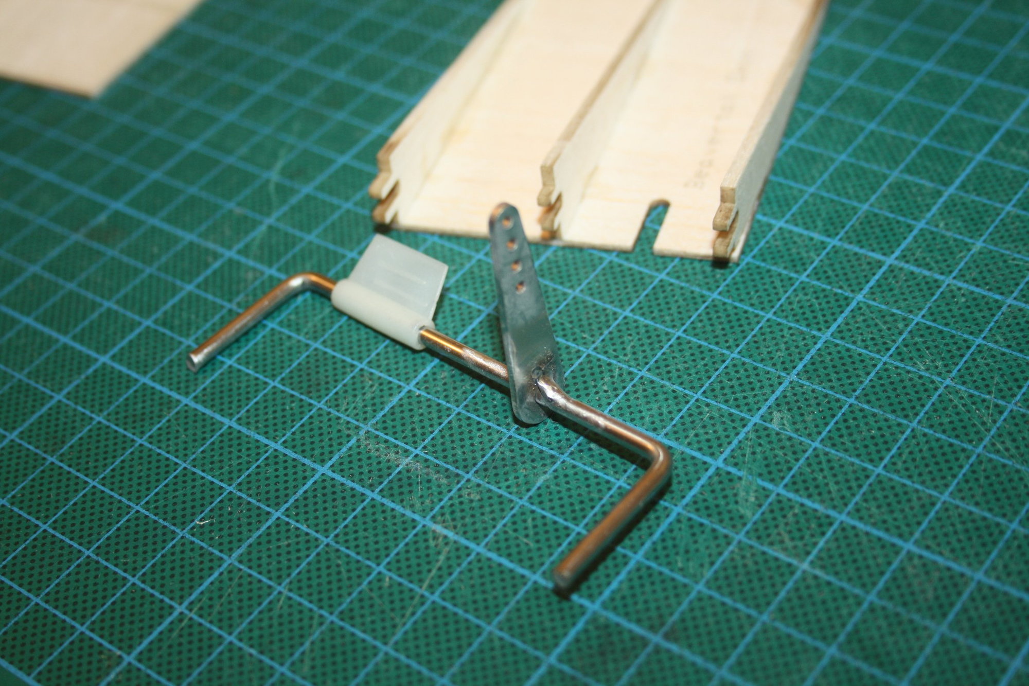
If you happen to have the DLE 20RA in your aeroplane, and it is not too much of a bother, I would like to see the throttle link / servo arrangement you ended up with, as well as where you ended up having the ignition module. It will save me from having to think about it : )
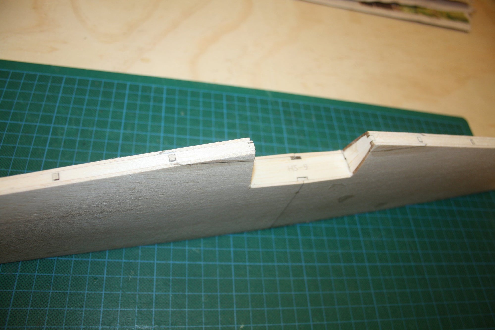
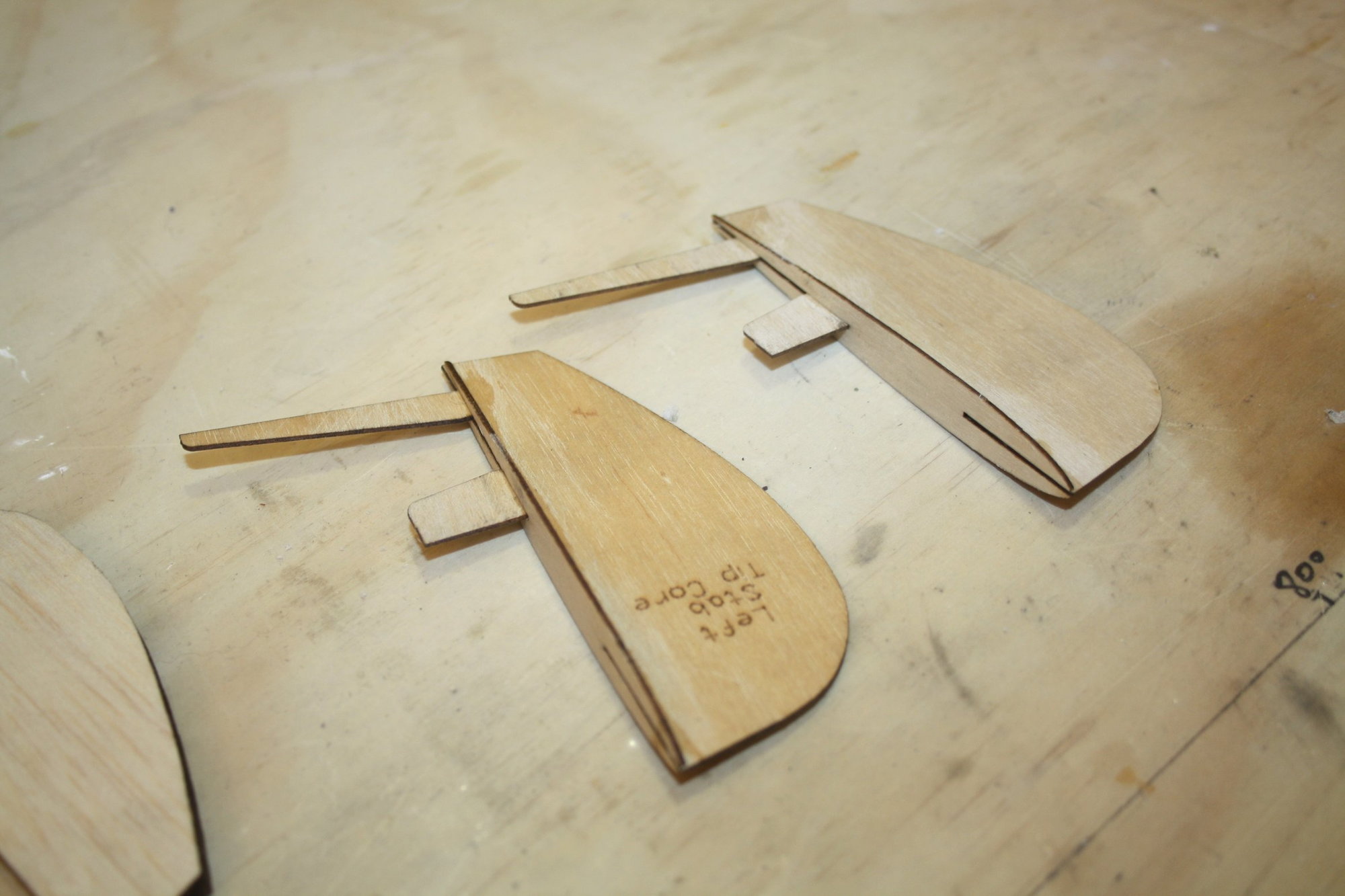
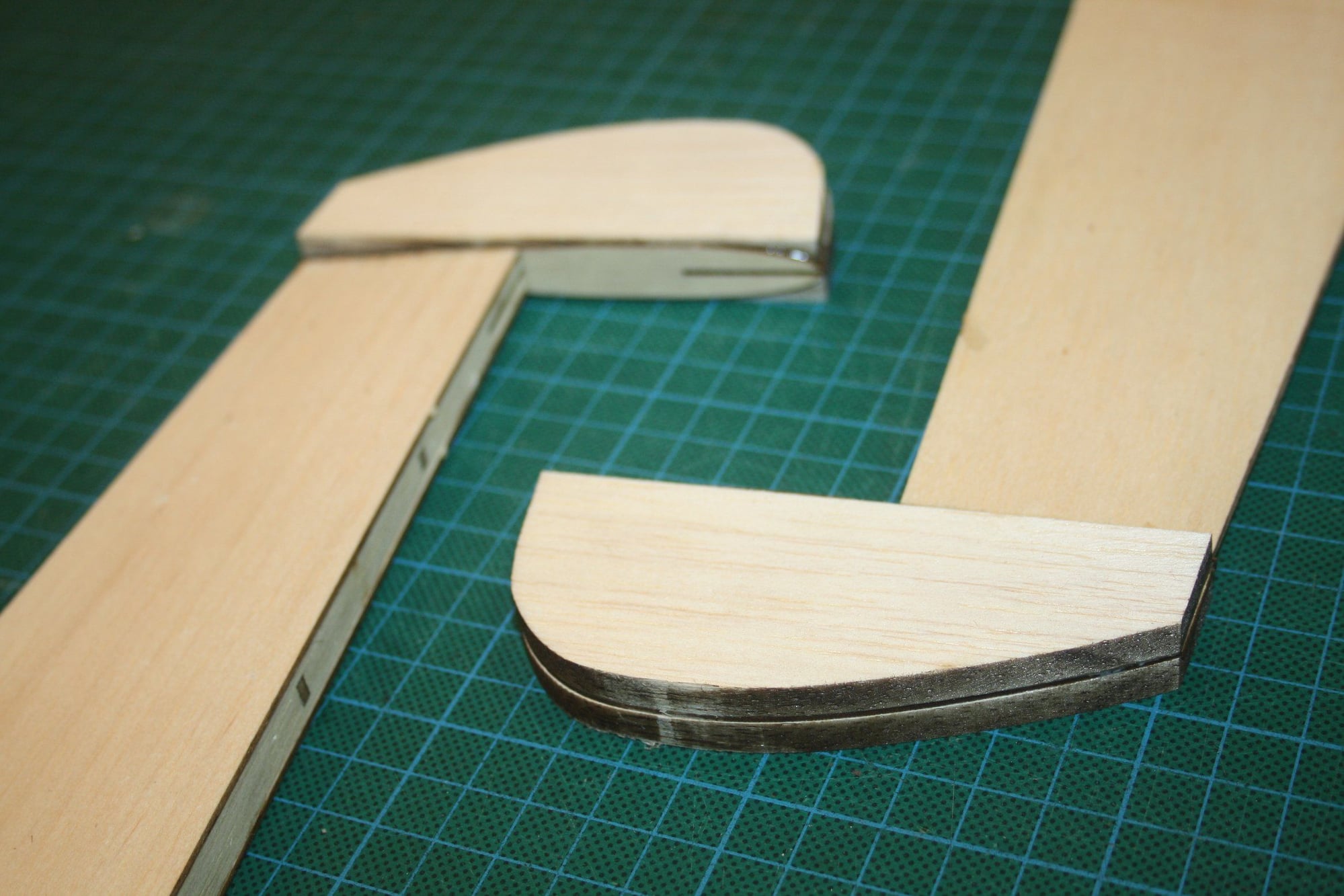
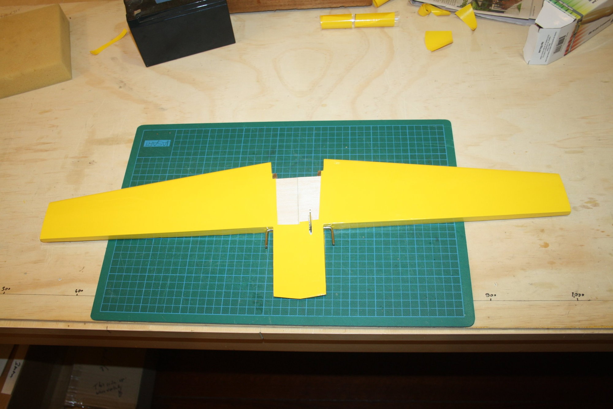
Since I am posting, some photos of the stabiliser tips and elevators assembly, to the point where the sheeting is ready to be beveled to match the ribs:
Cheers,
Eran
If you happen to have the DLE 20RA in your aeroplane, and it is not too much of a bother, I would like to see the throttle link / servo arrangement you ended up with, as well as where you ended up having the ignition module. It will save me from having to think about it : )
Since I am posting, some photos of the stabiliser tips and elevators assembly, to the point where the sheeting is ready to be beveled to match the ribs:
Cheers,
Eran
06-25-2022, 12:40 PM
#12
Eran,
I'm sorry I'm not able to help you with throttle linkage. For the past several years, I have gone strictly electric. I still love the sounds and smells that ICEs produce, but my age and health do not allow me to fiddle with them at the field anymore. So, my Beaver is powered by a RimFire .80 on a 6-cell, 6,000mAh battery.
I applaud you making the effort to post photos of your build. I agree that the instruction manual leaves something to be desired. I can clearly remember pausing my build to pull up the online version to magnify the pictures. And even then it was sometimes hard to figure out what was going on. Please carry on.
Again, sorry about not being able to assist with your throttle situation.
Take care,
Bren
06-27-2022, 04:16 AM
#13
Thread Starter
Bren - No worries at all, I hope you find the electric version satisfying. I think it is great that our hobby enables the variety of options we enjoy today.
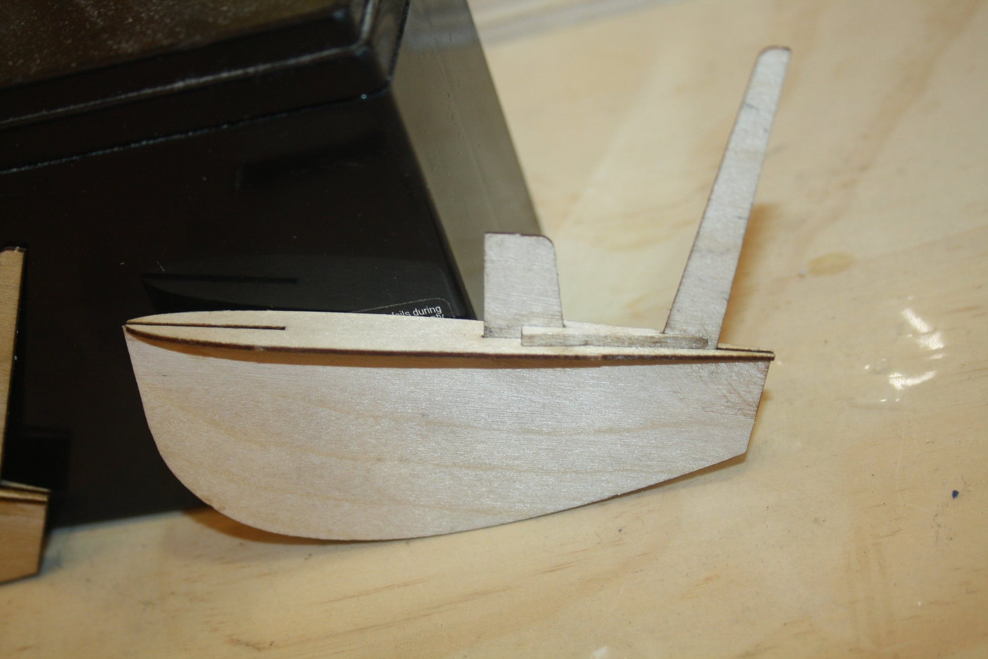
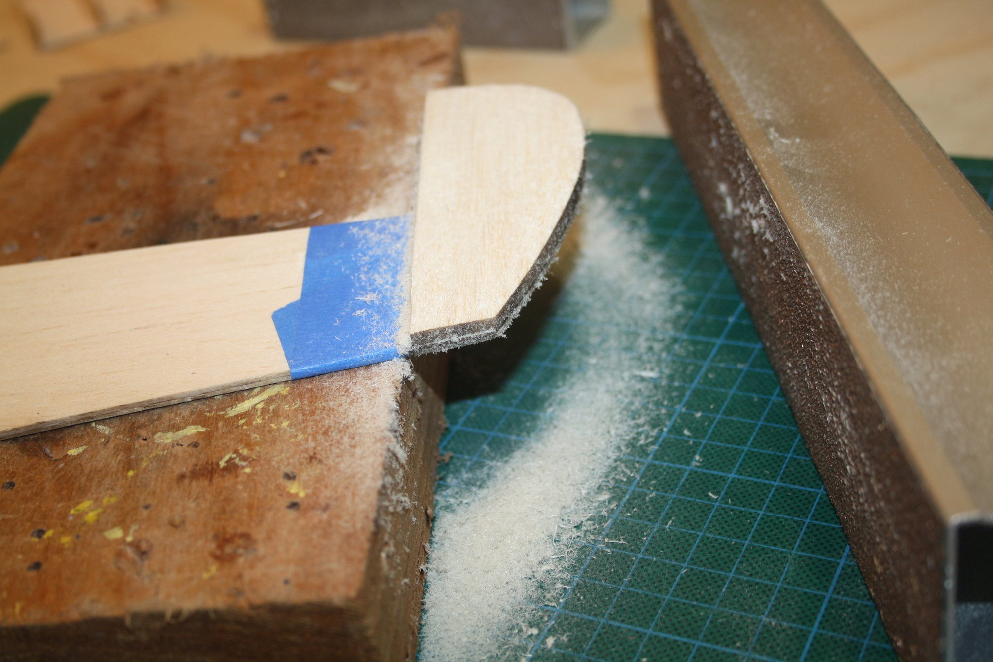
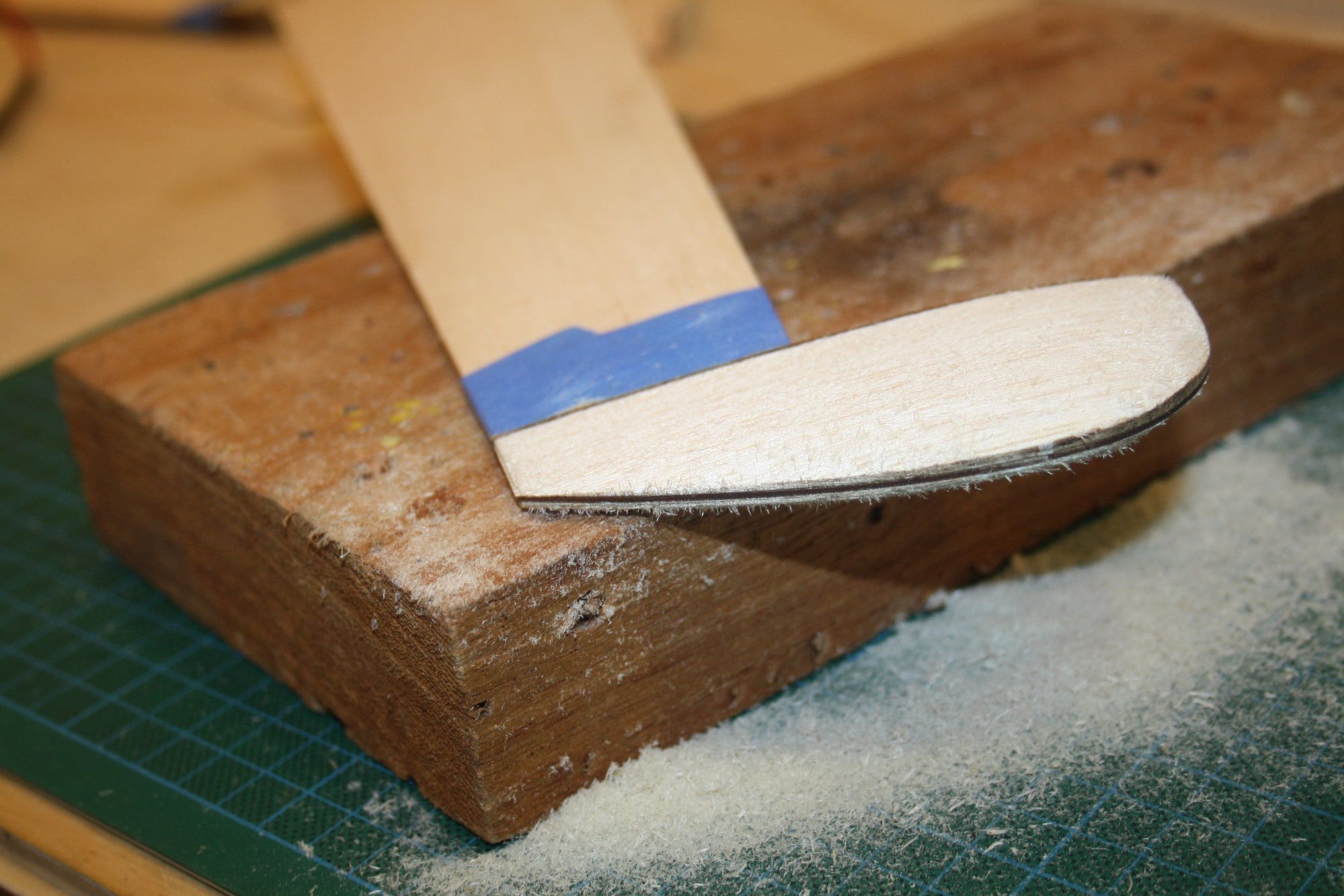
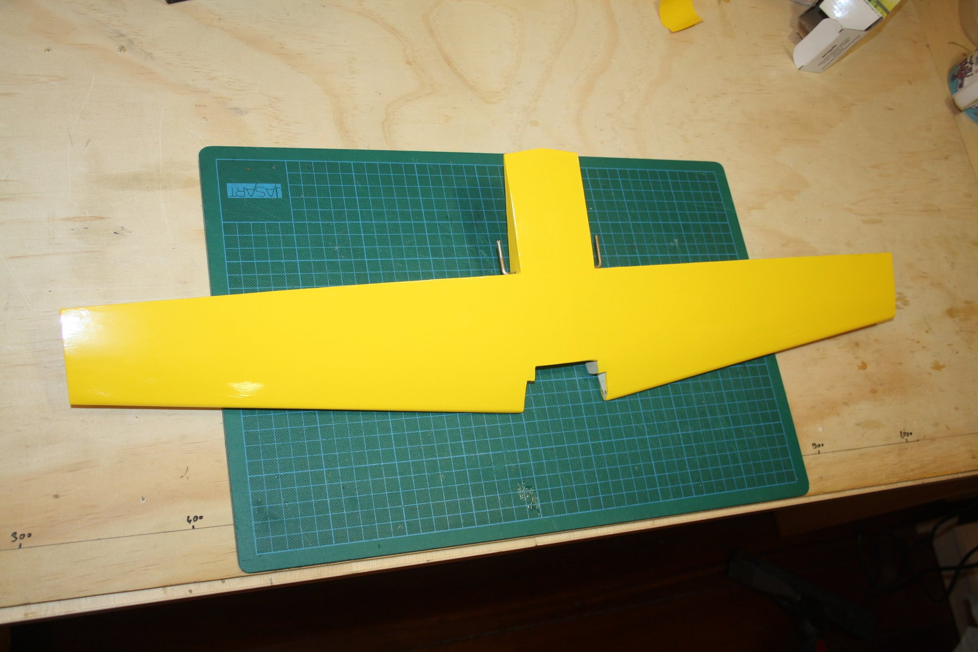
Some more photos of the elevators, with the bevel sanded on the "bottom" sheeting, the tips plywood center in place and fully enclosed by the "top" sheeting.
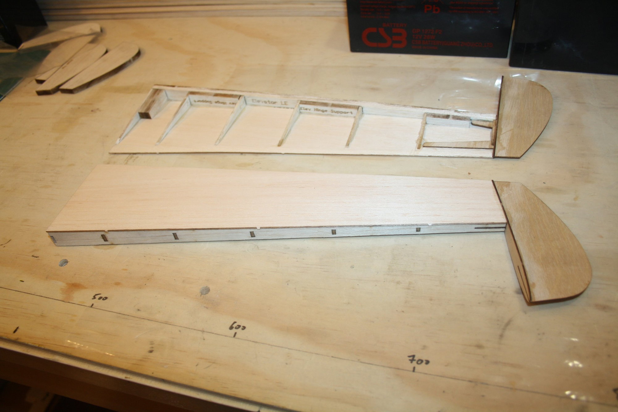
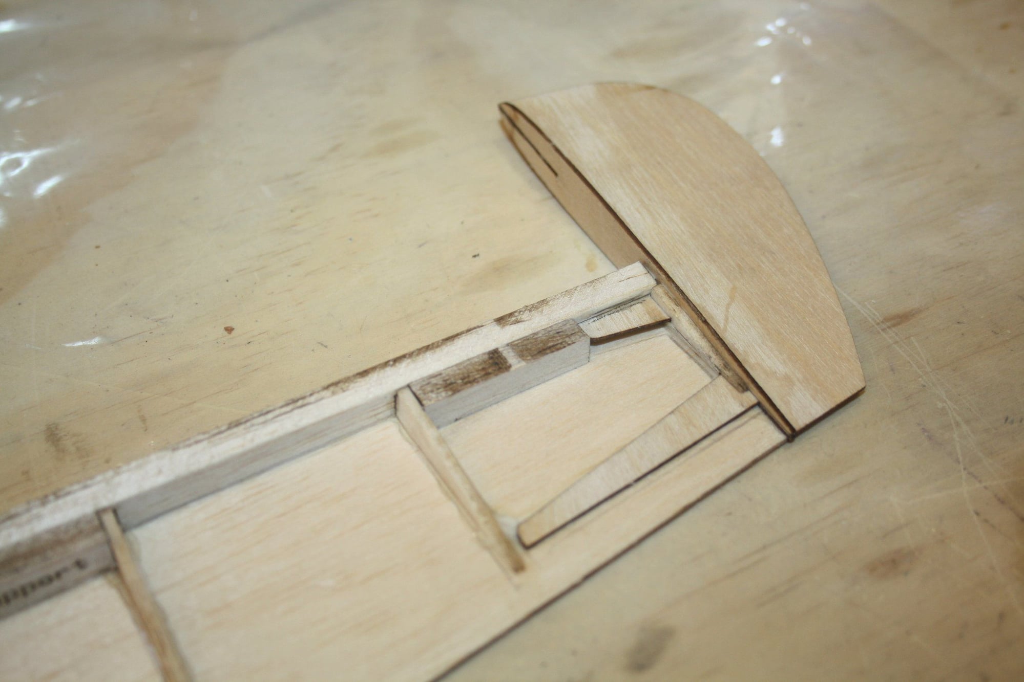
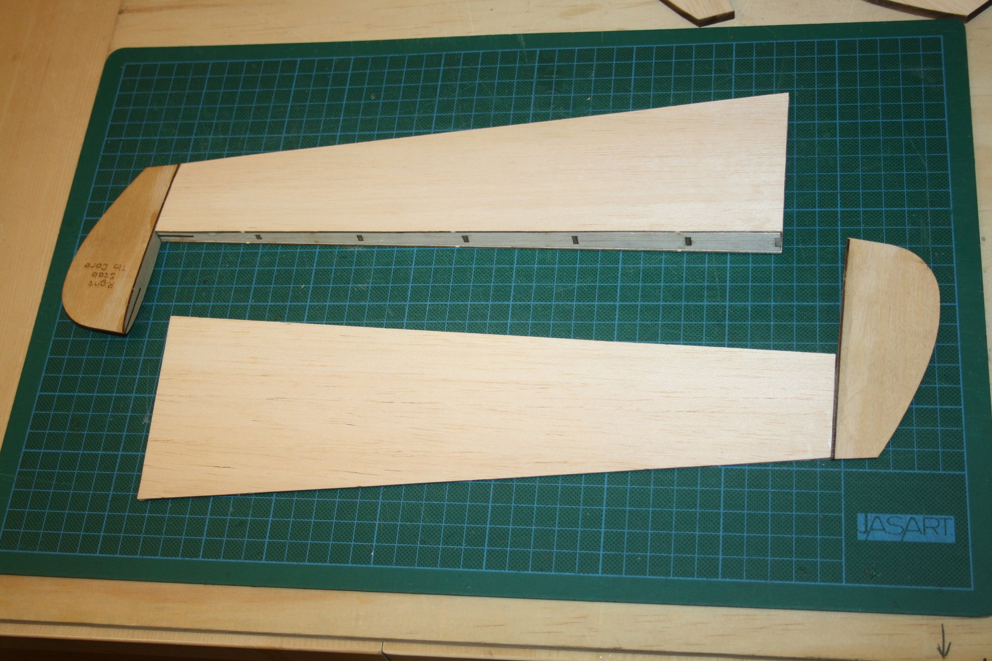
Some more photos of the elevators, with the bevel sanded on the "bottom" sheeting, the tips plywood center in place and fully enclosed by the "top" sheeting.


 07-13-2022, 01:49 AM
#18
Thread Starter
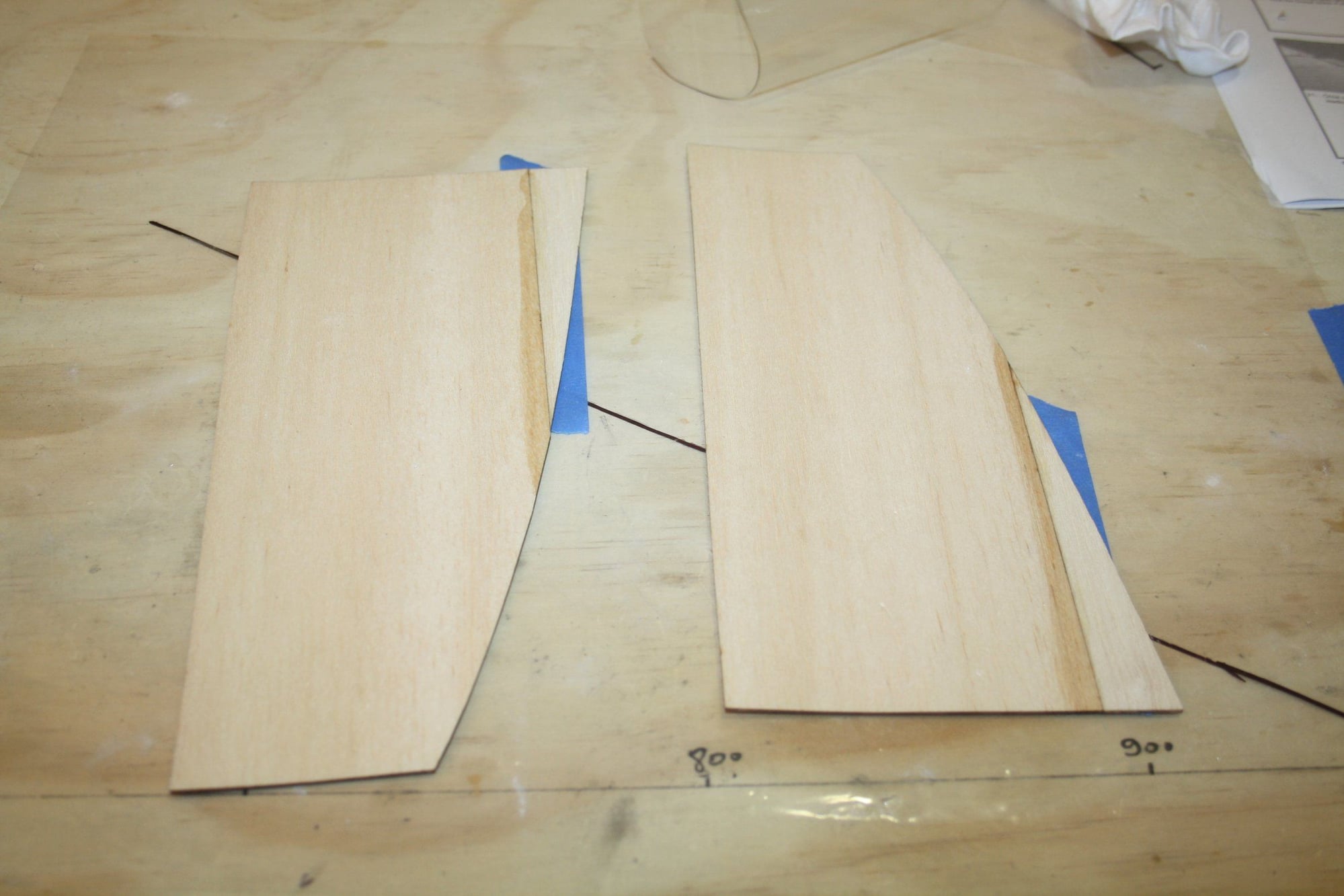
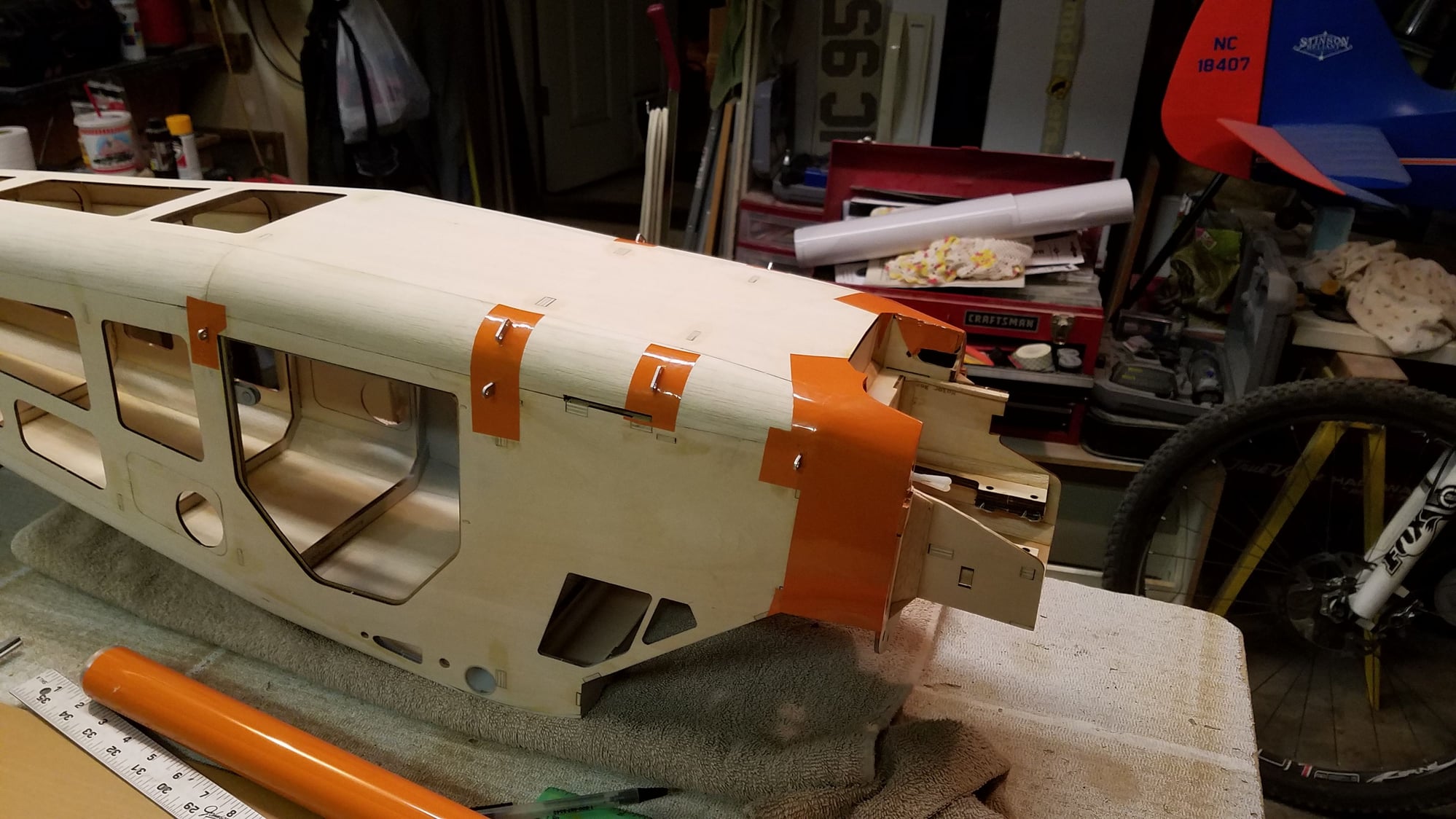
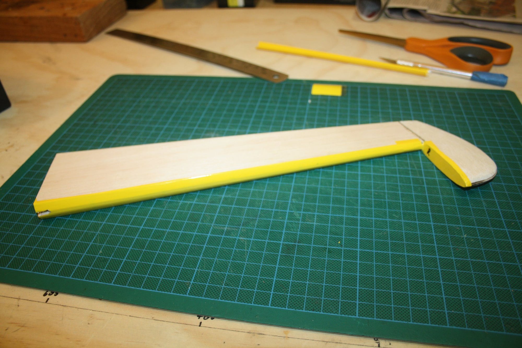
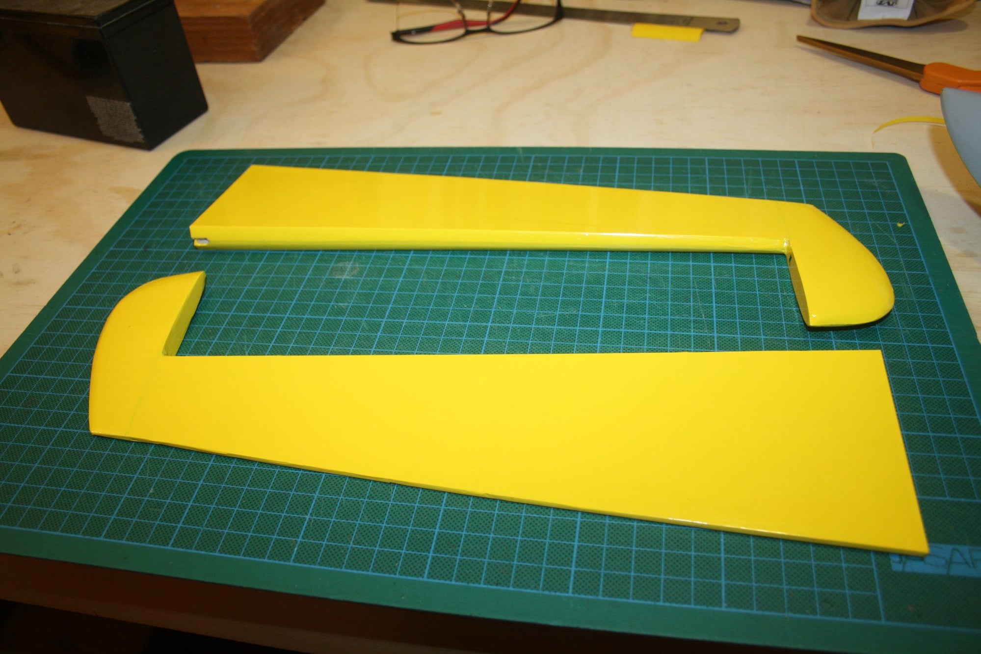
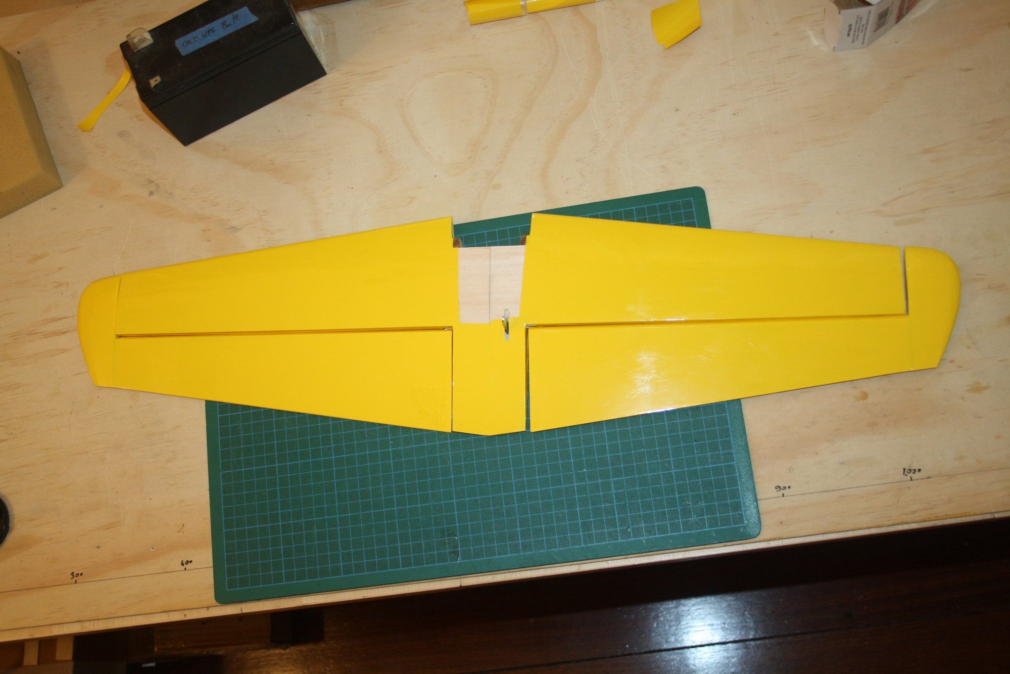
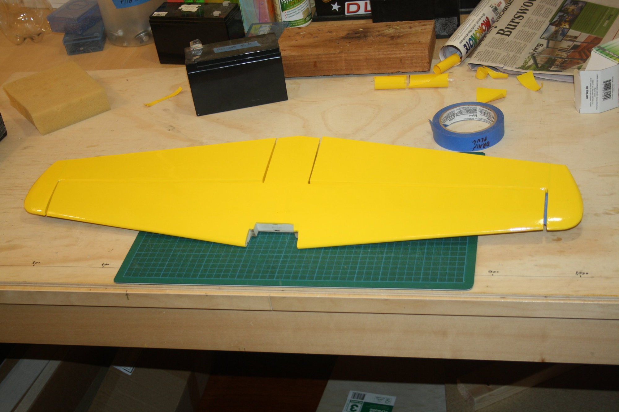
I prefer to cover major components as when they are ready, eventually ending up with an ARF "kit"... Top tip if you are new to covering is to cover the areas with 90 degree angles or that are difficult to cover by using the main covering pieces first.
Cheers,
Eran
Cheers,
Eran
 07-13-2022, 07:54 PM
#20
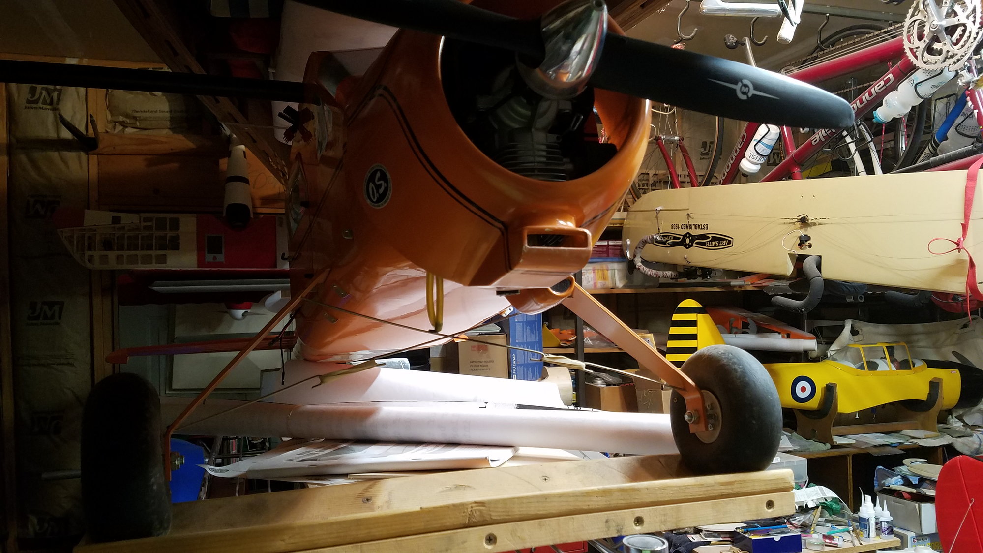
Not sure if this helps on the throttle servo as I used an OS GT22, the ignition is on top of the motor mount inside the cowl and the servo is a metal gear hitec 85 inside the cabin next to the fuel tank
 looks like I lost a piece of nose weight.

looks like I lost a piece of nose weight.Last edited by bryanmiick; 07-13-2022 at 07:58 PM.
07-14-2022, 05:18 AM
#22
Thread Starter
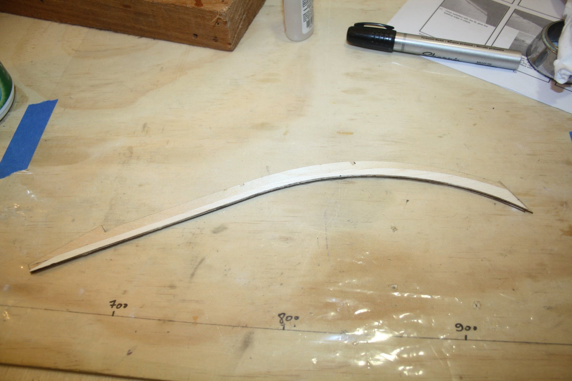
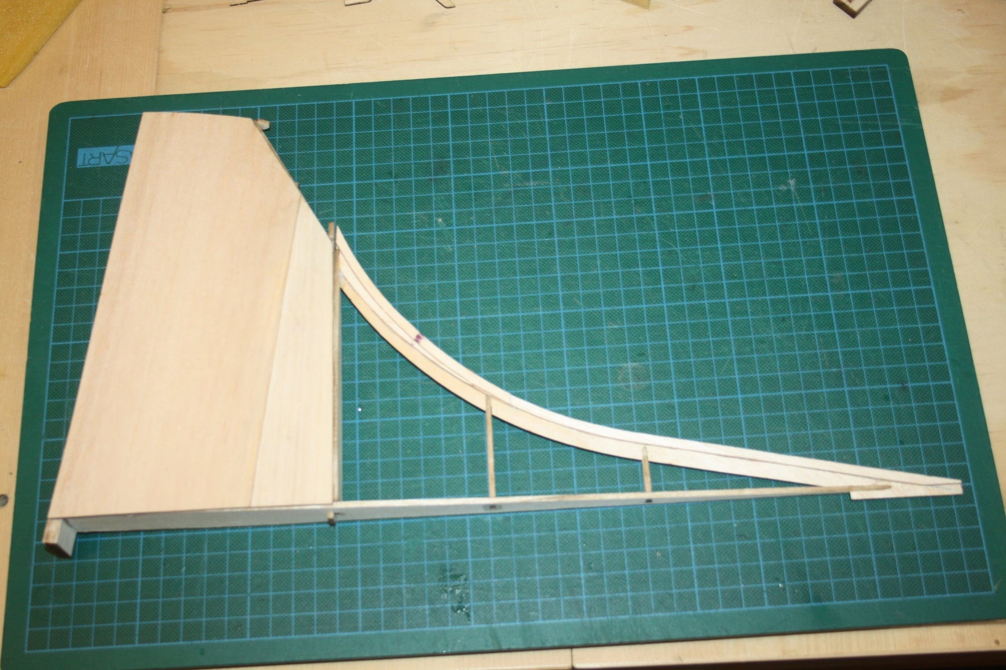
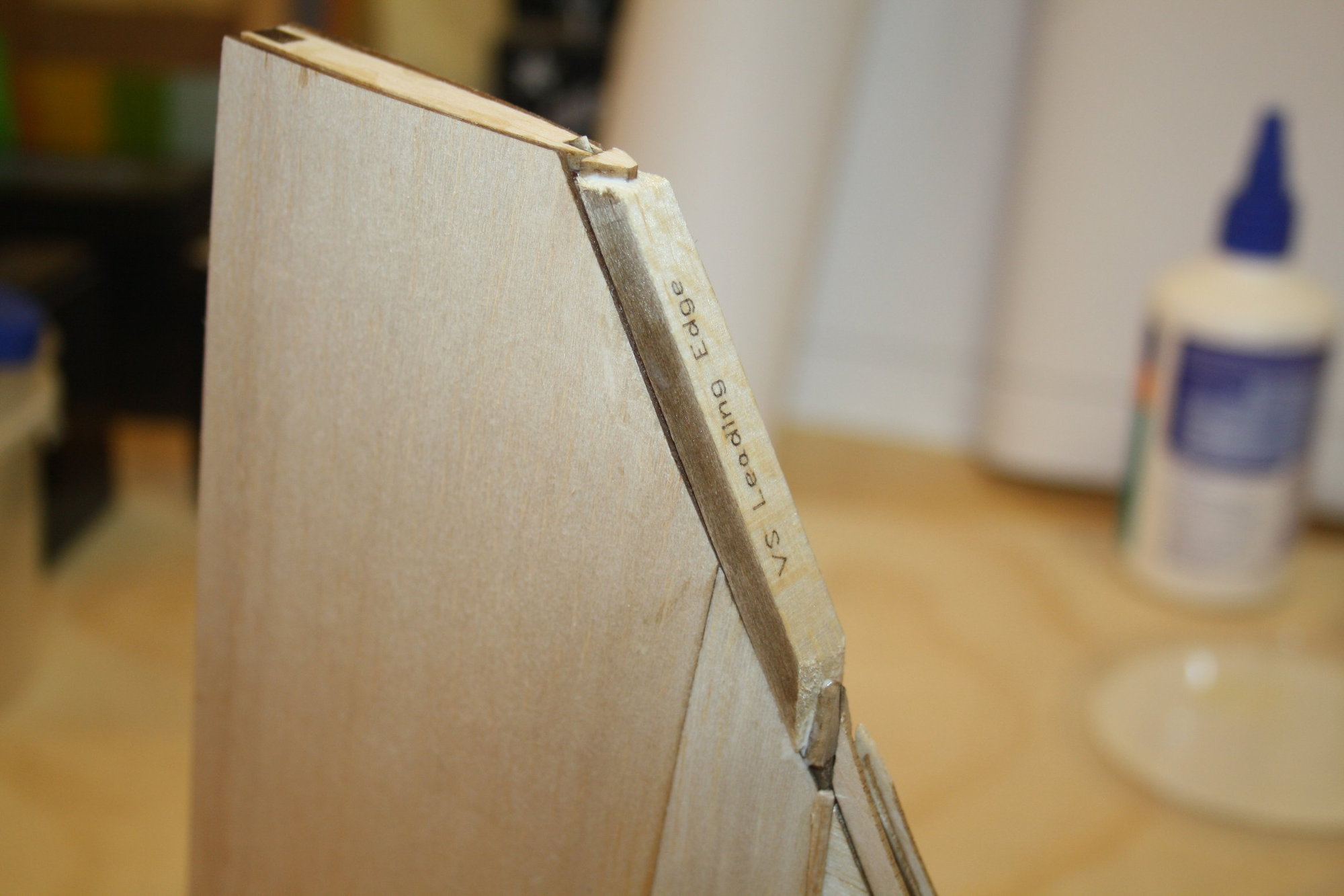
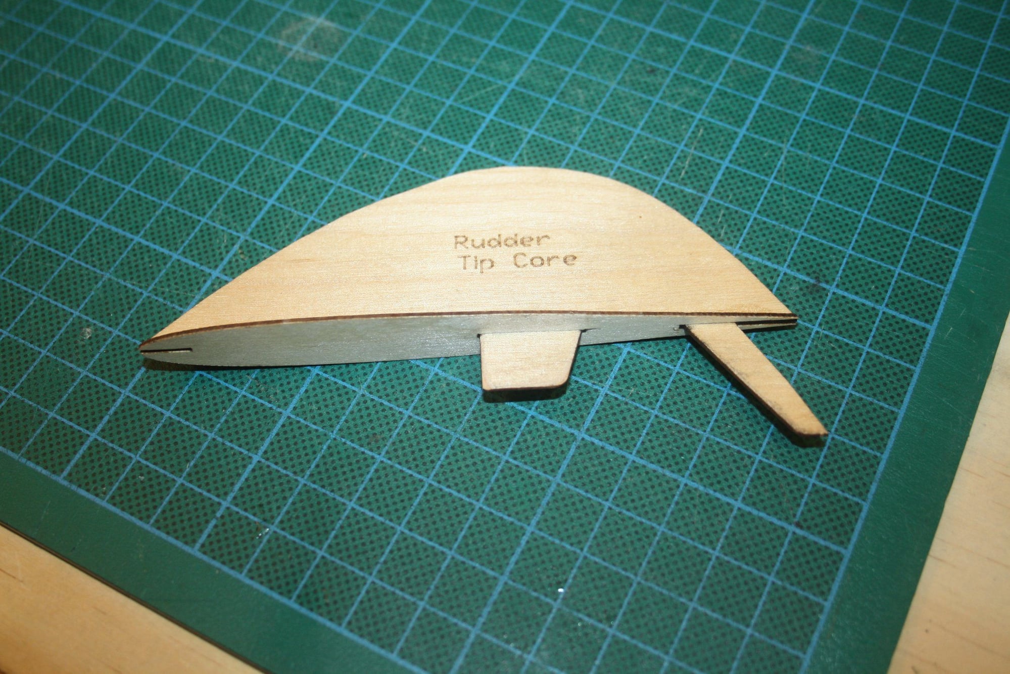
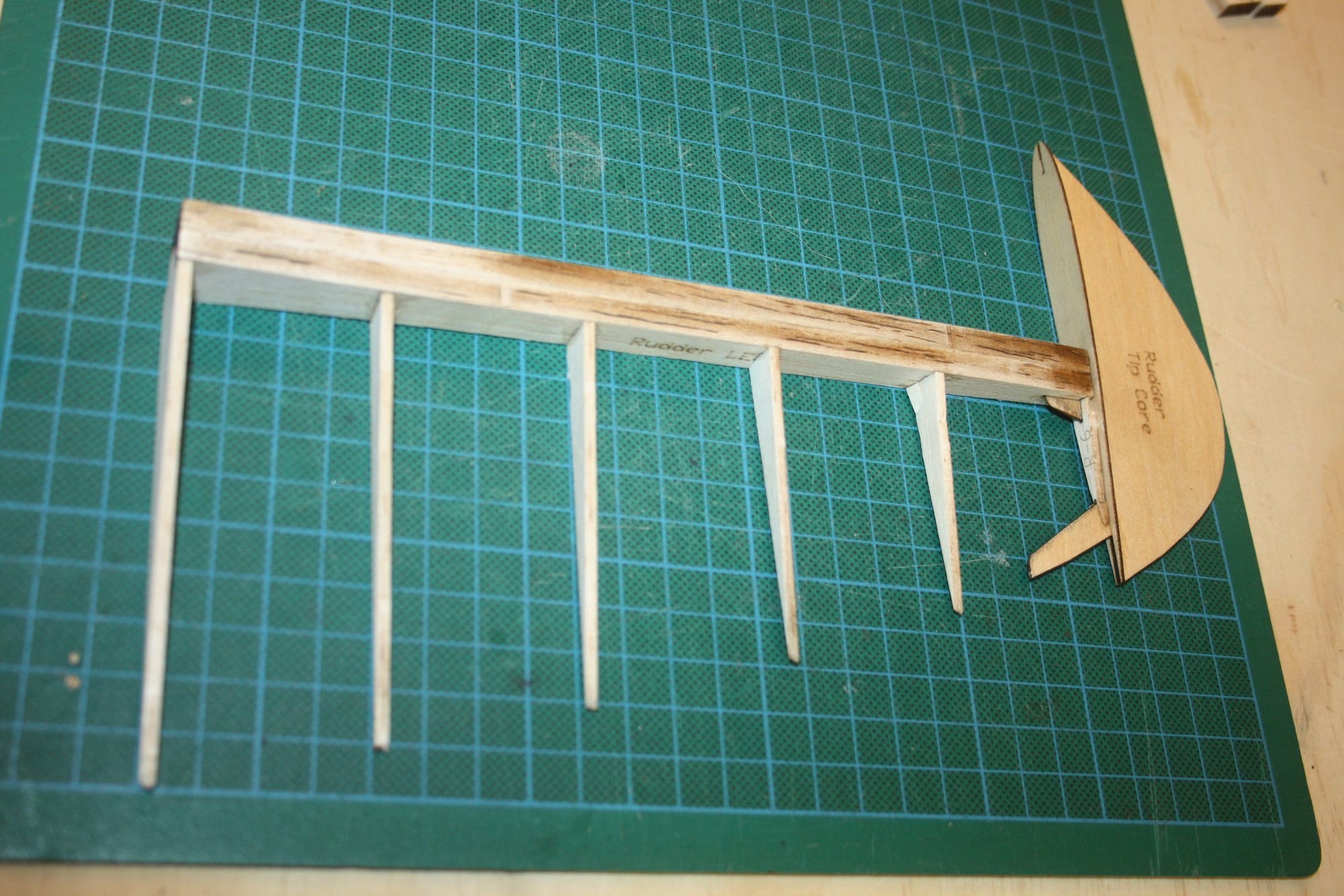
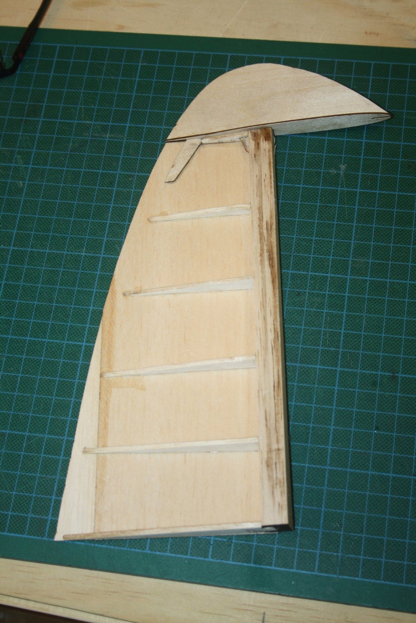
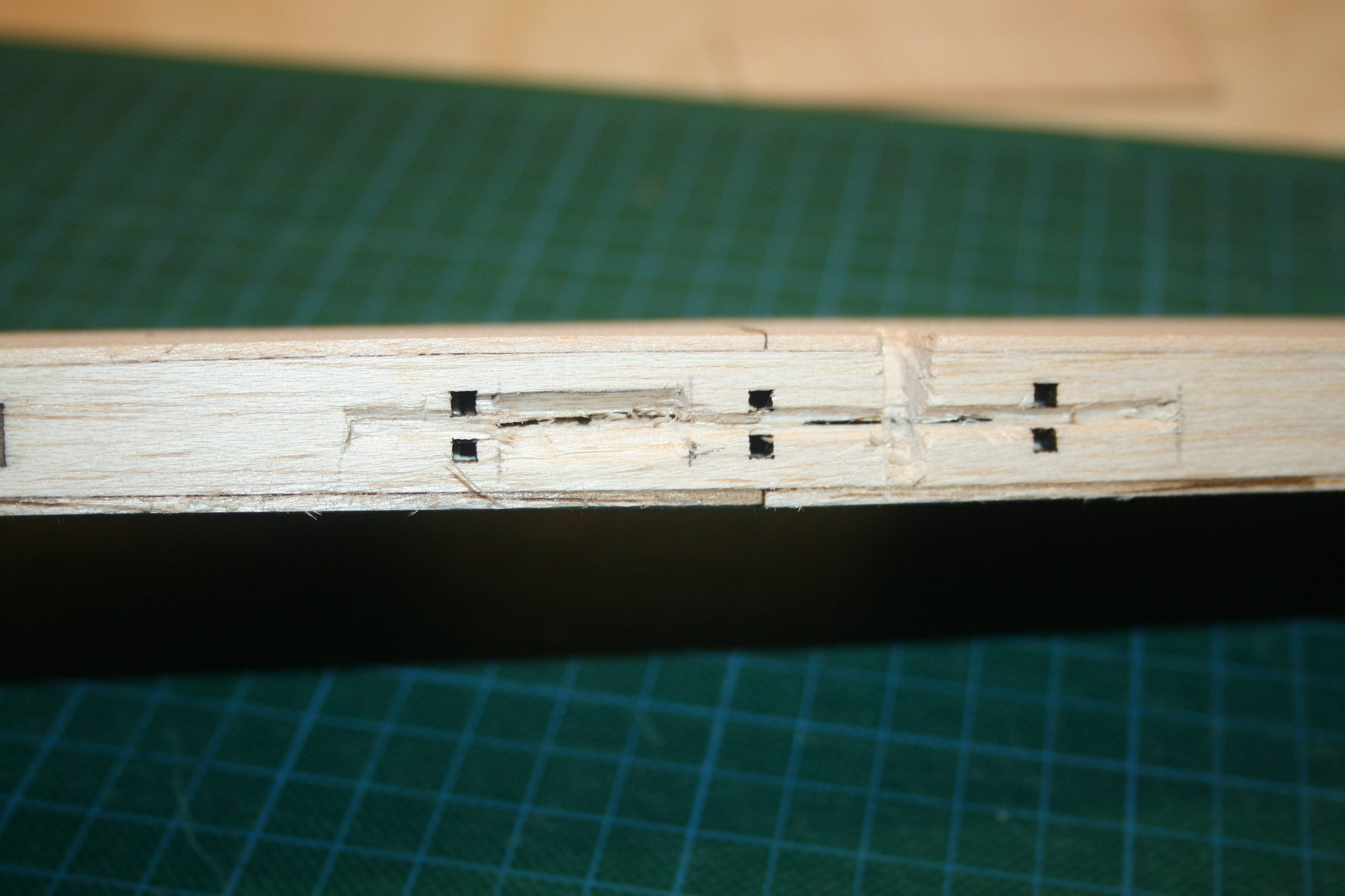
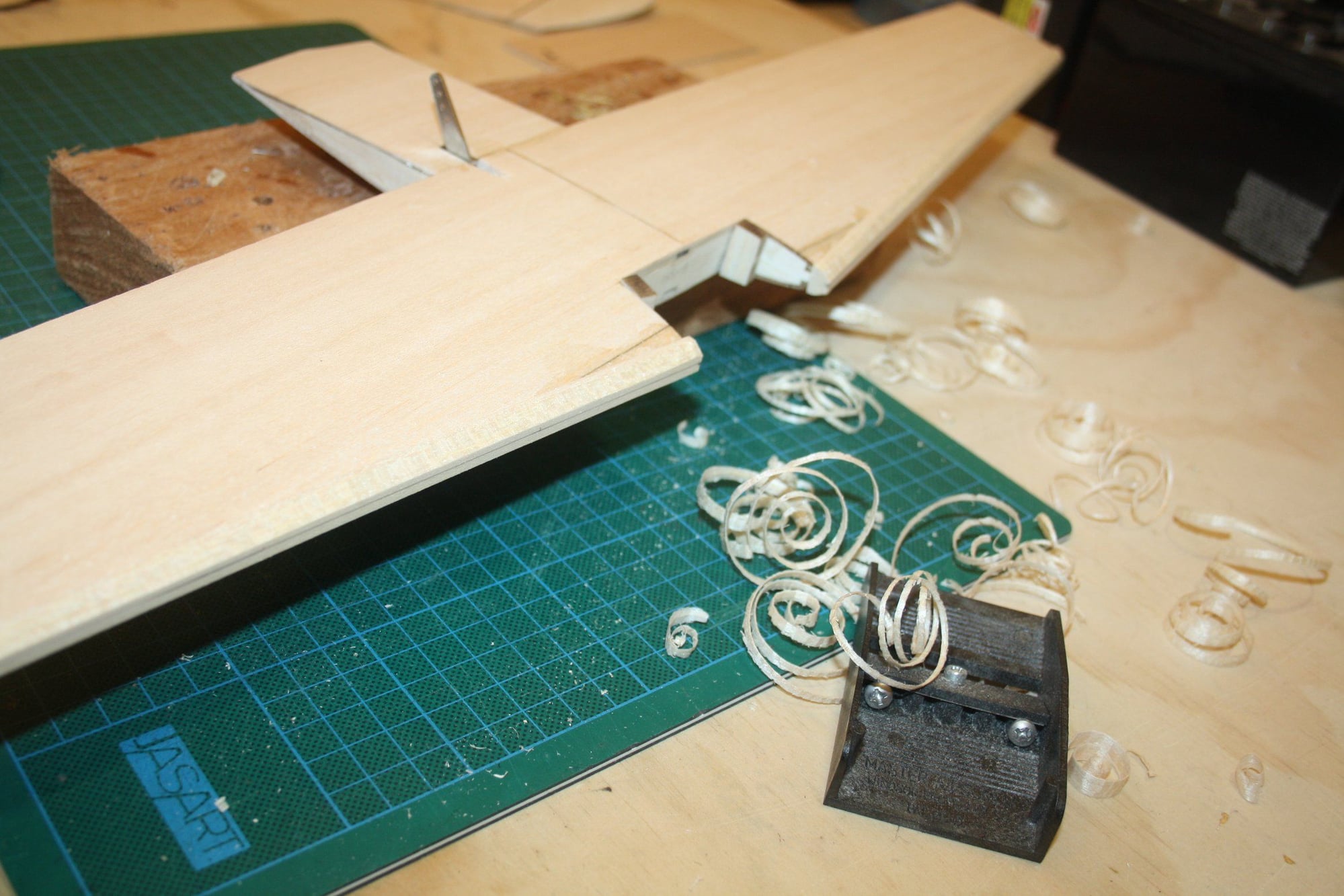
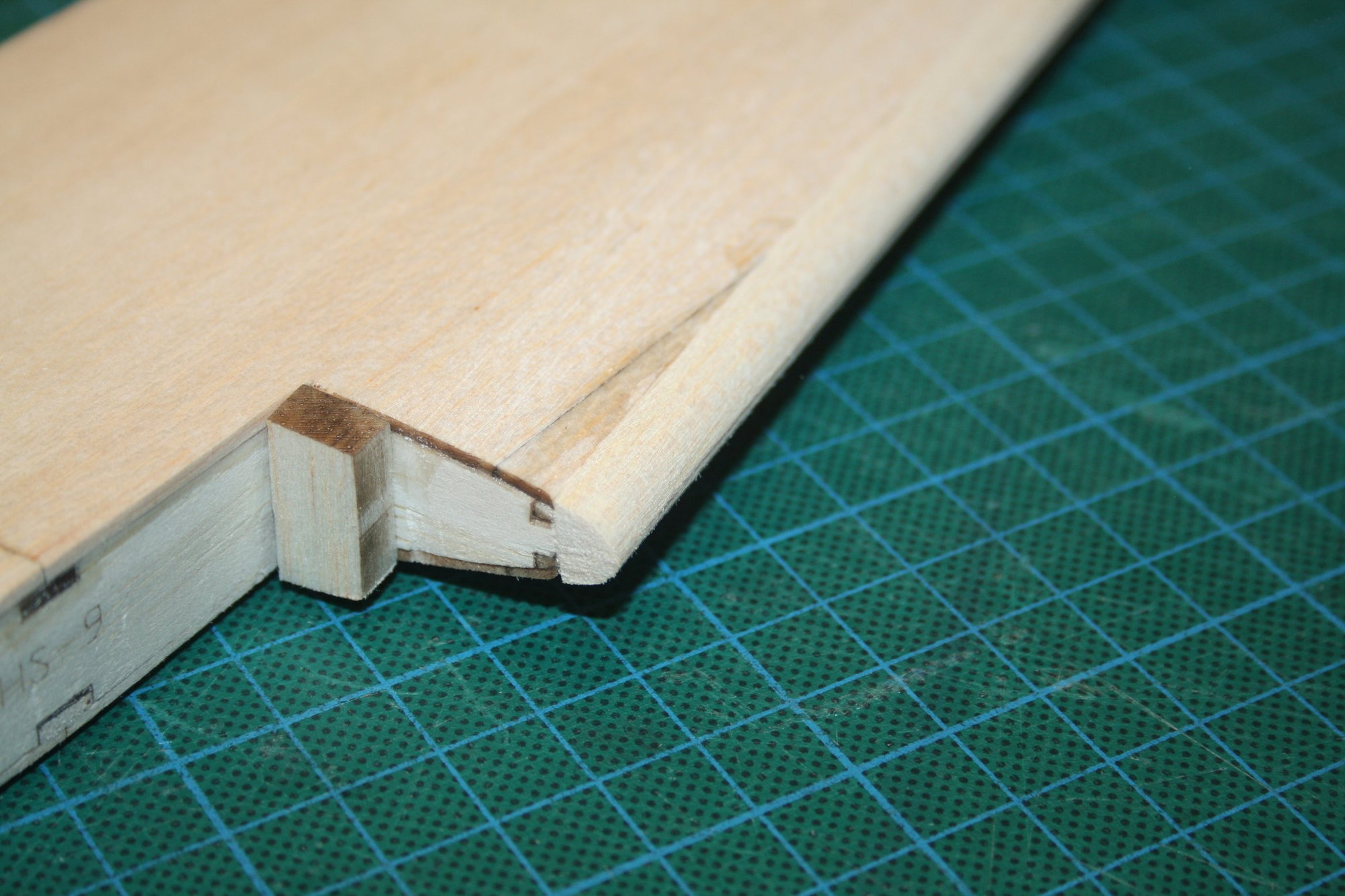
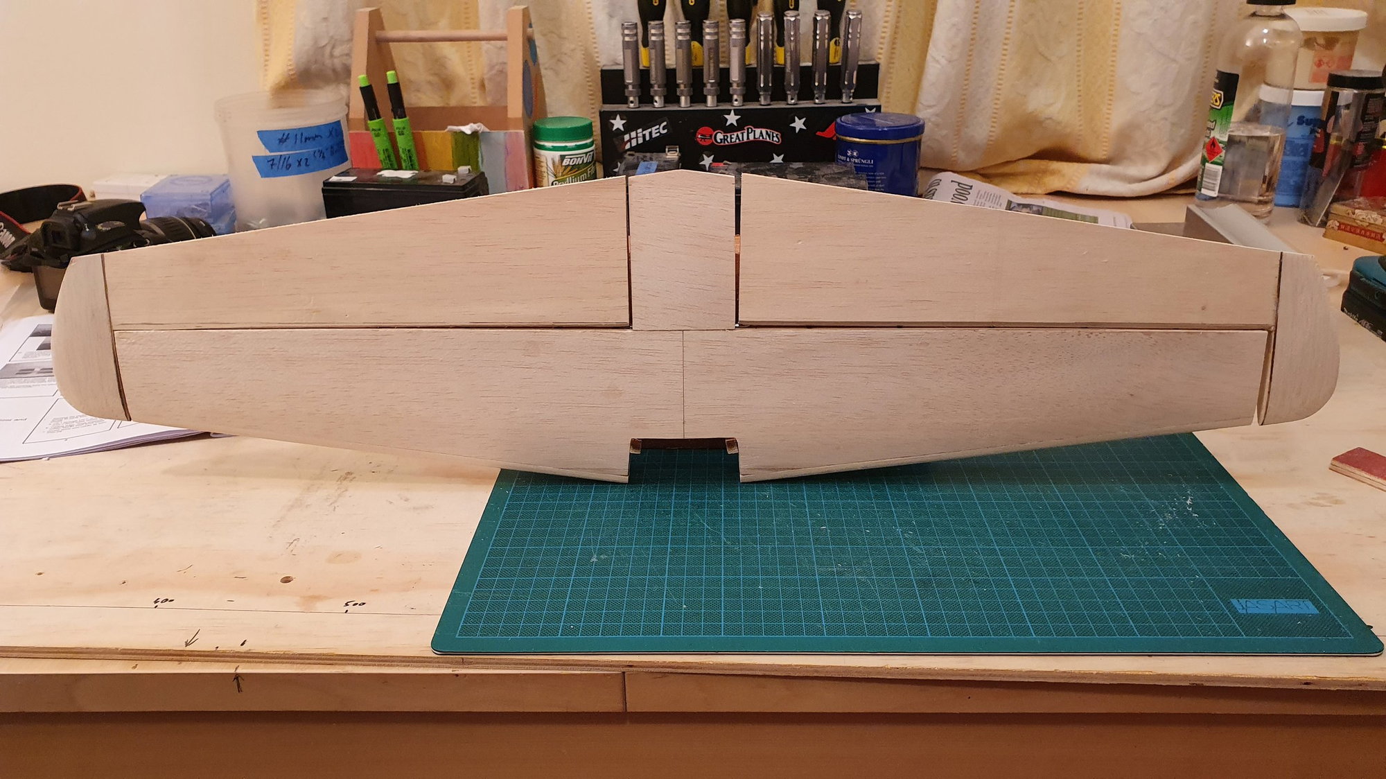
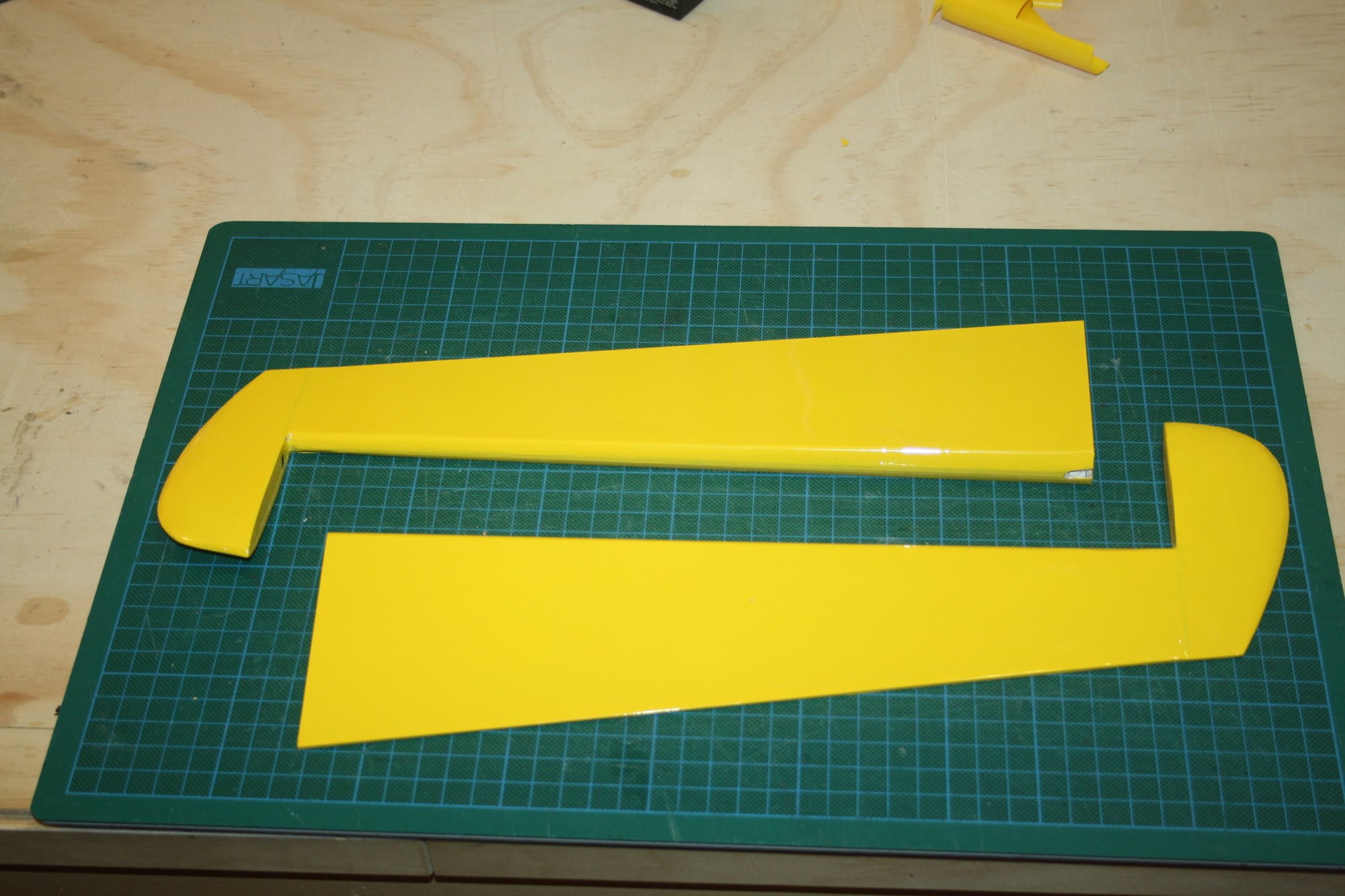
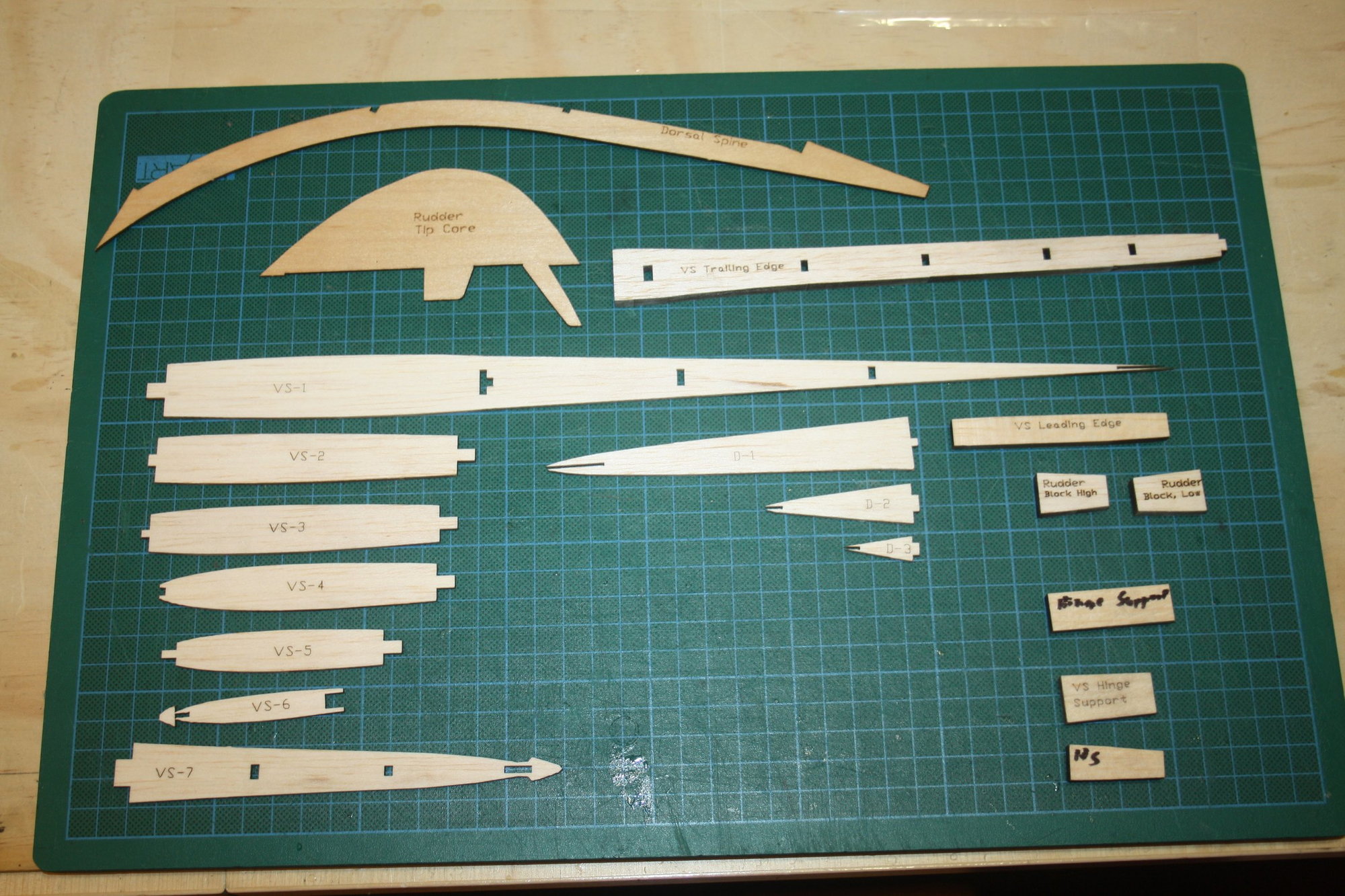
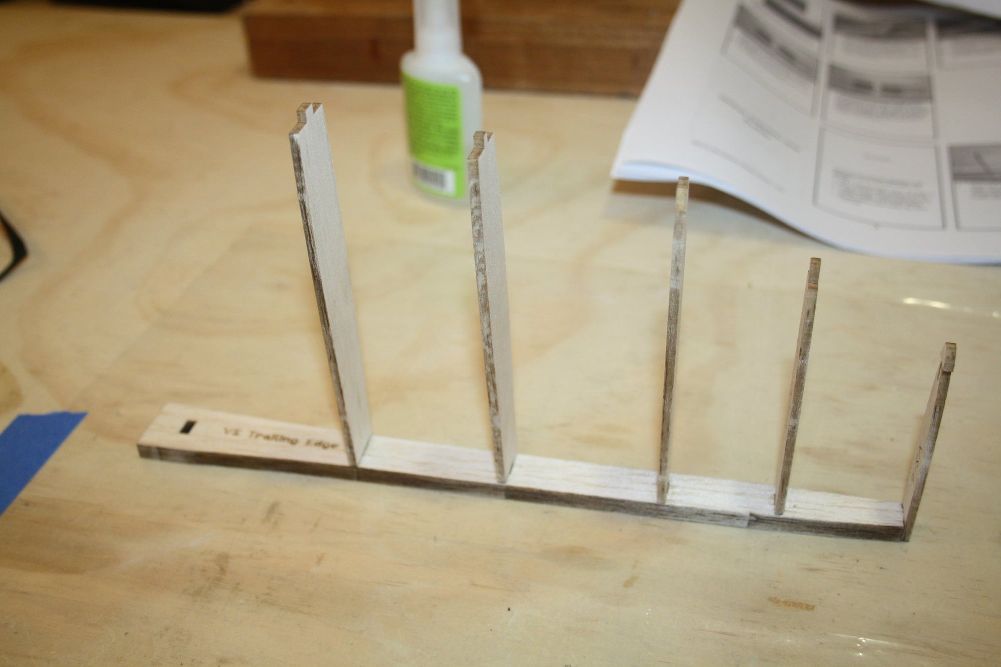
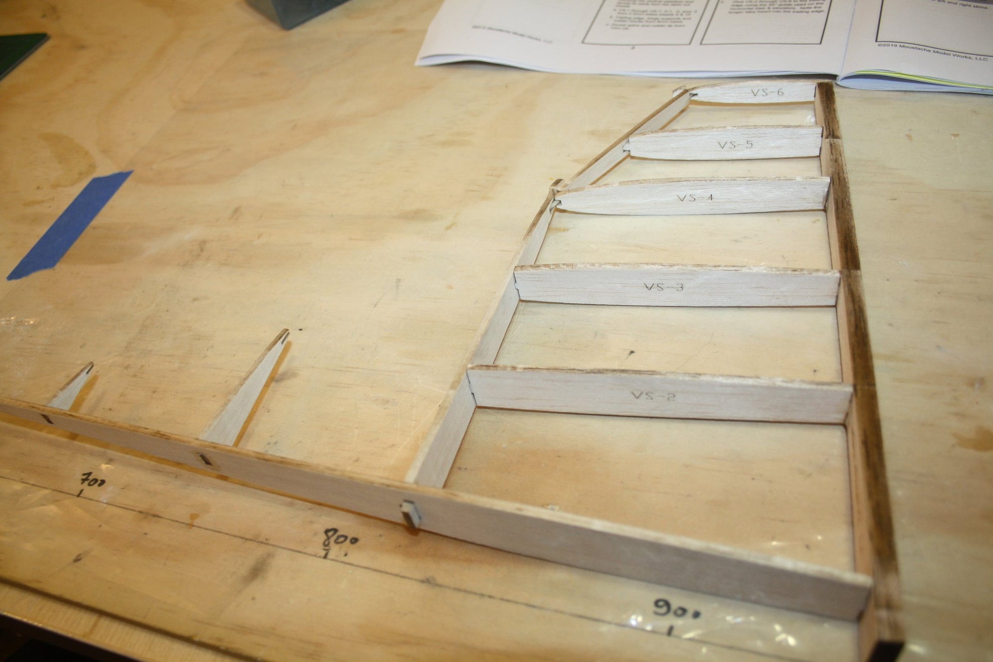
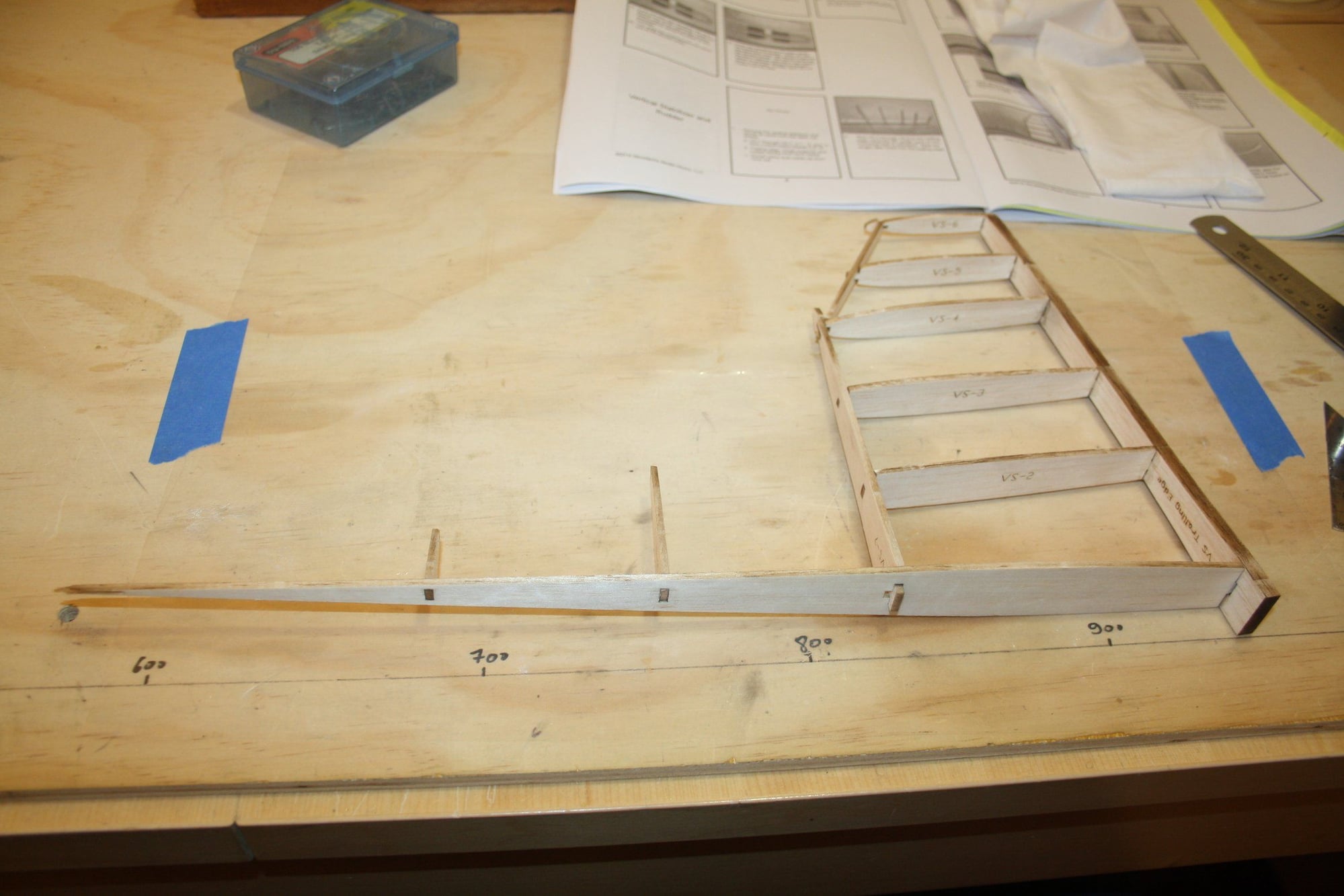
The way that the vertical stabiliser is build was a first for me. I thoroughly enjoyed it. This section demonstrated what is possible with modern 3D design and laser cutting.
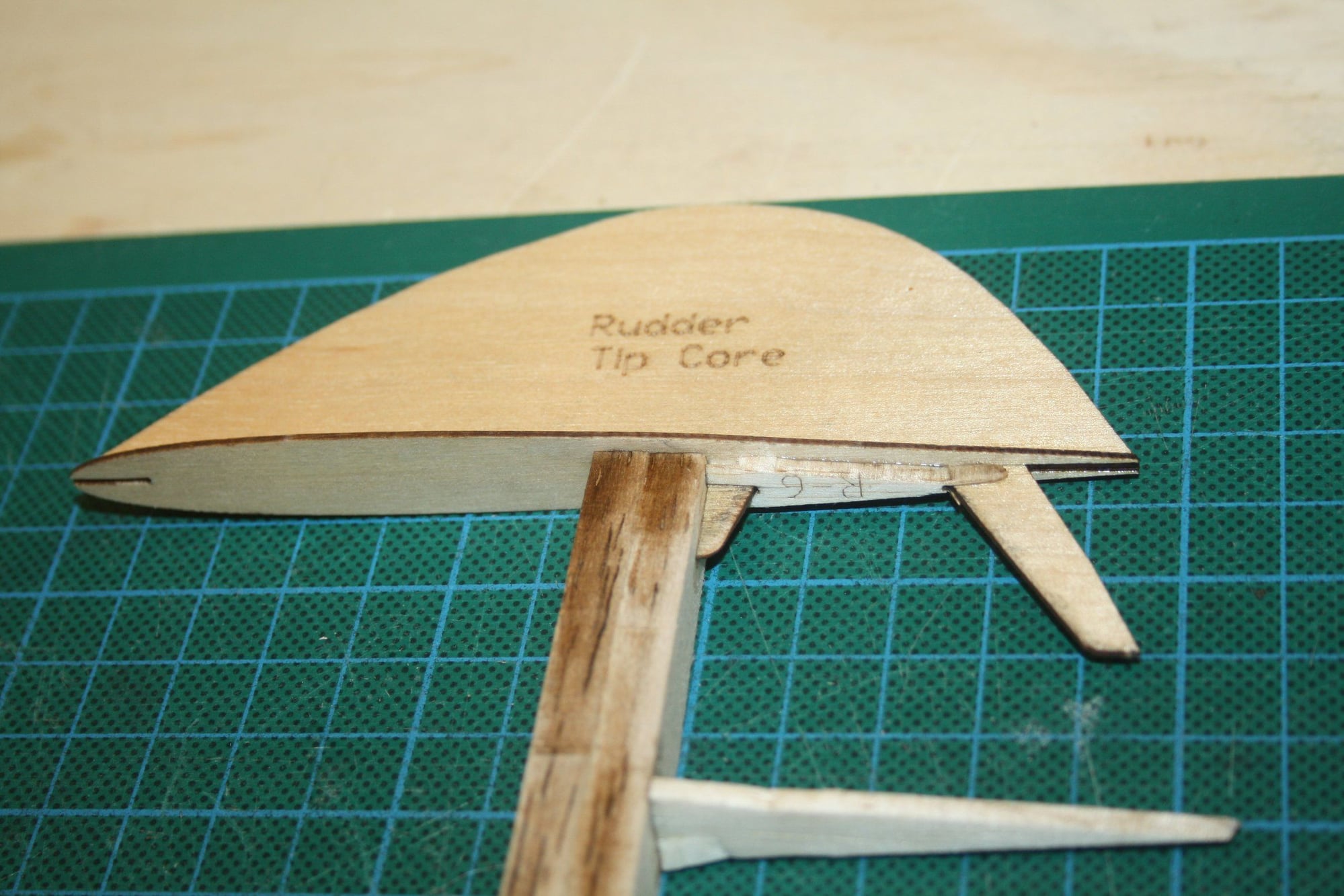
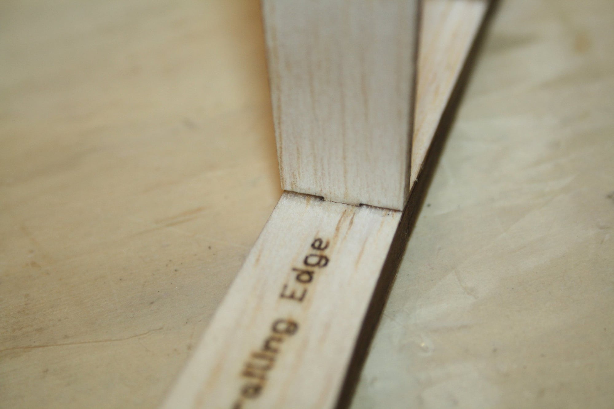
However, the lack off engineering thinking was evident with the variance in material thickness not taken into account for tolerances. The trailing edge was thinner then the designer took into consideration resulting in a gap as seen in the photos. All ribsv required minor sanding to fix this issue.

Cheers,
Eran
However, the lack off engineering thinking was evident with the variance in material thickness not taken into account for tolerances. The trailing edge was thinner then the designer took into consideration resulting in a gap as seen in the photos. All ribsv required minor sanding to fix this issue.
Cheers,
Eran
07-17-2022, 02:50 AM
#23
Thread Starter
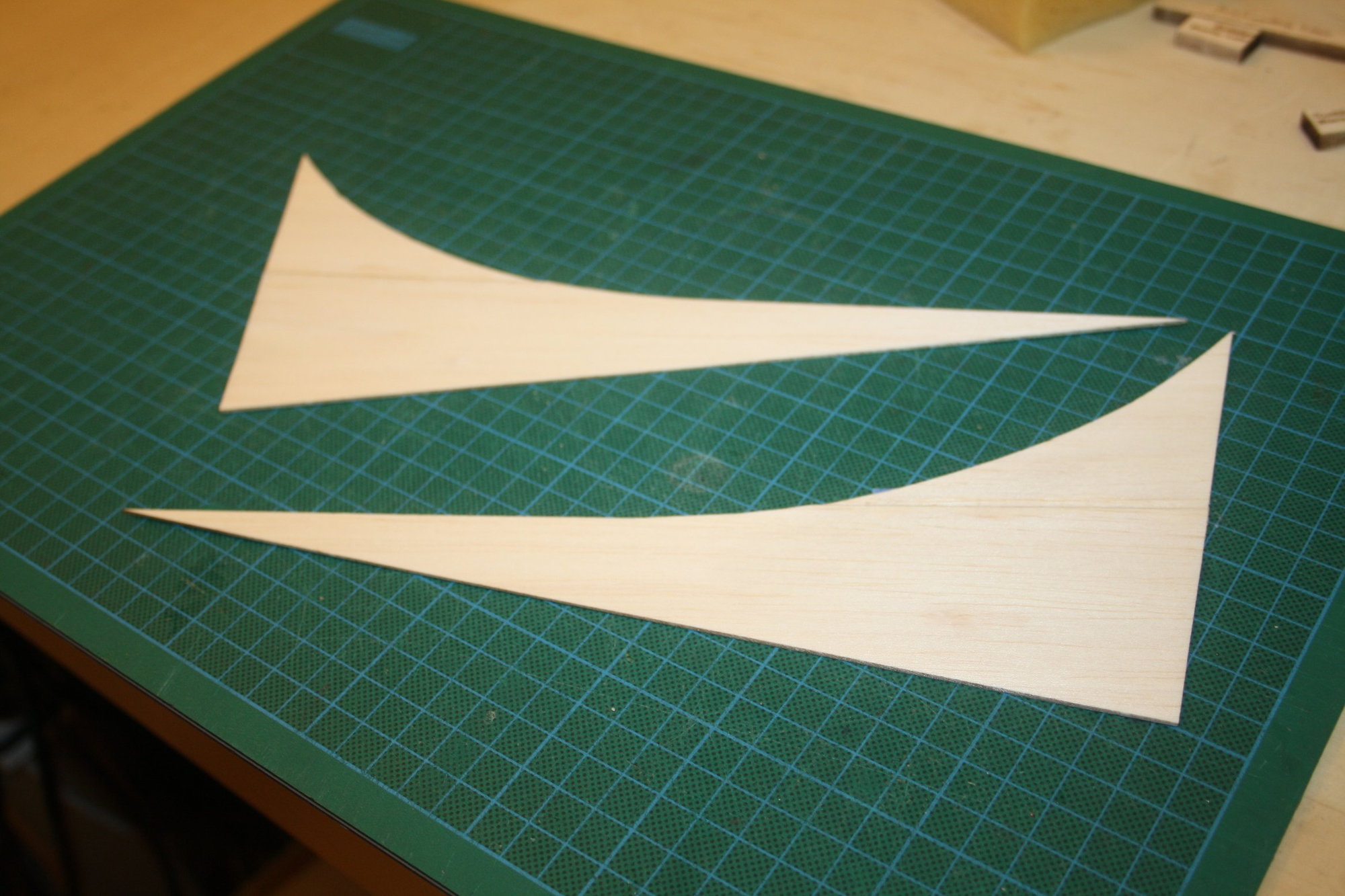
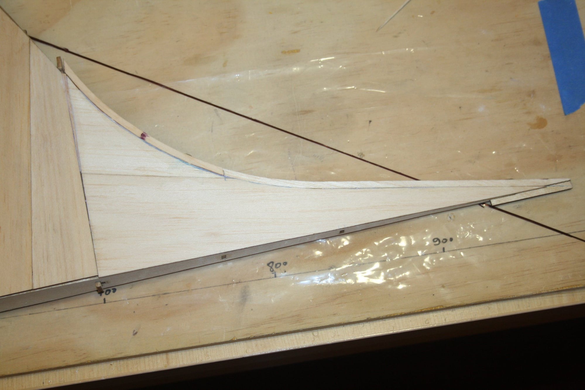
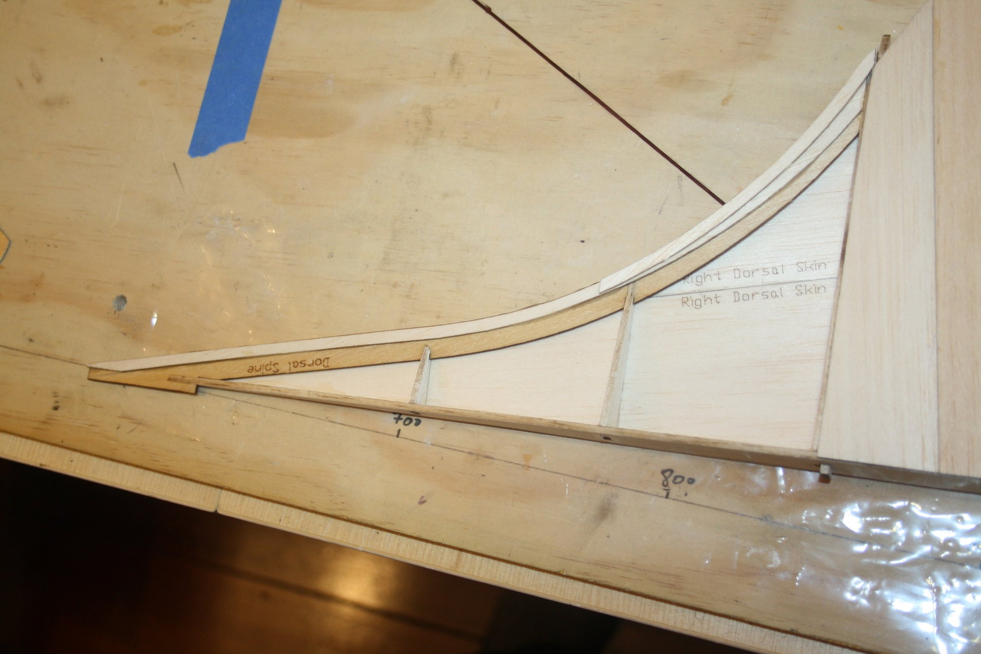
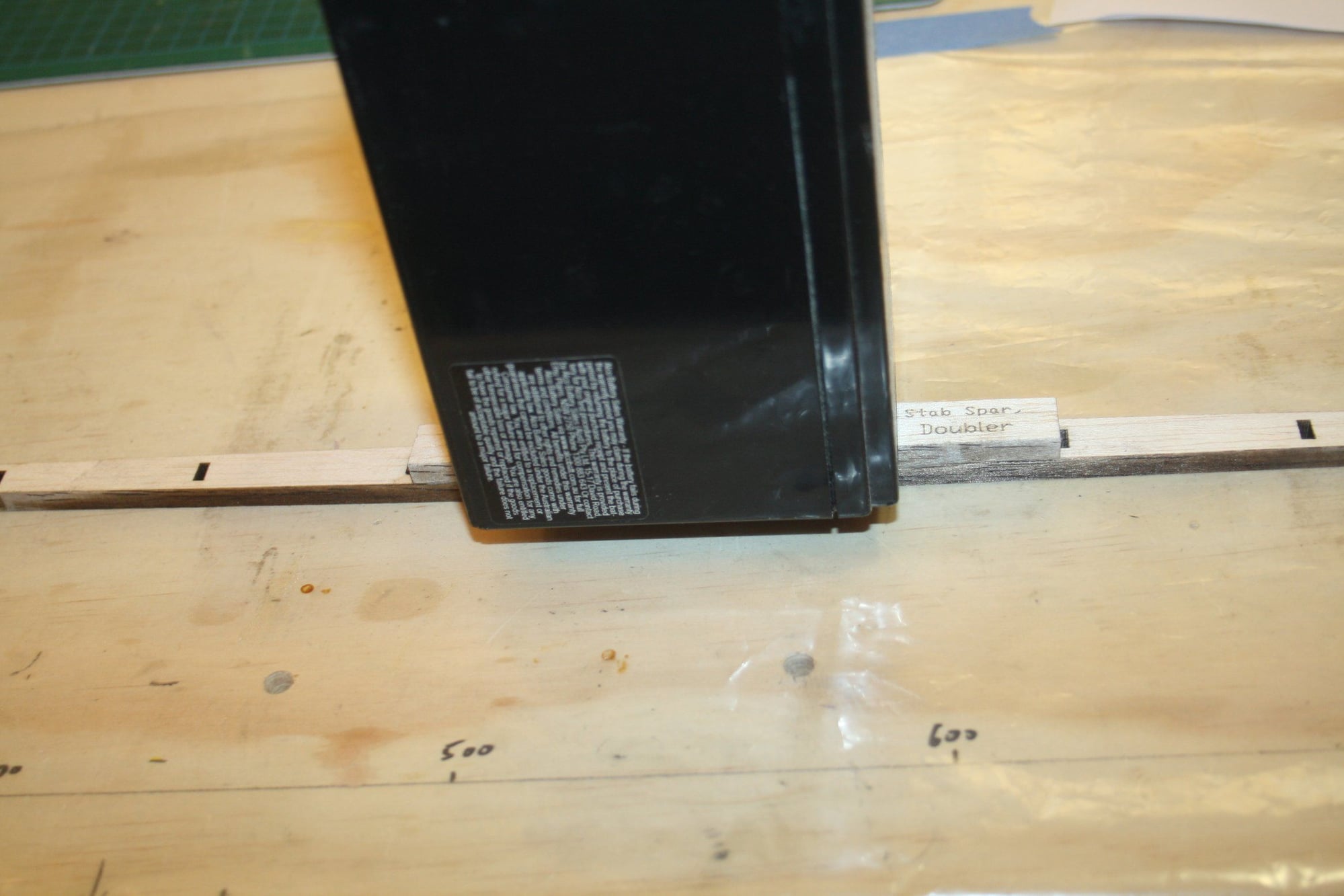
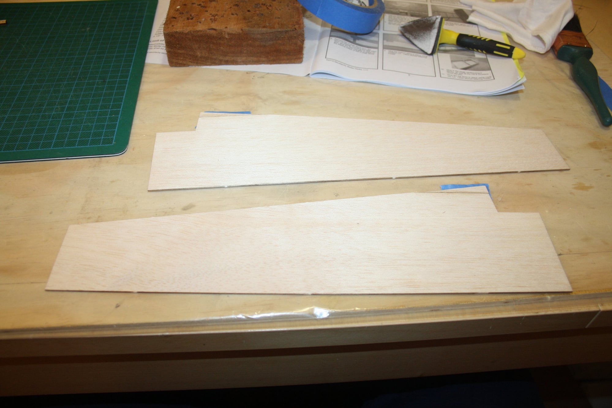
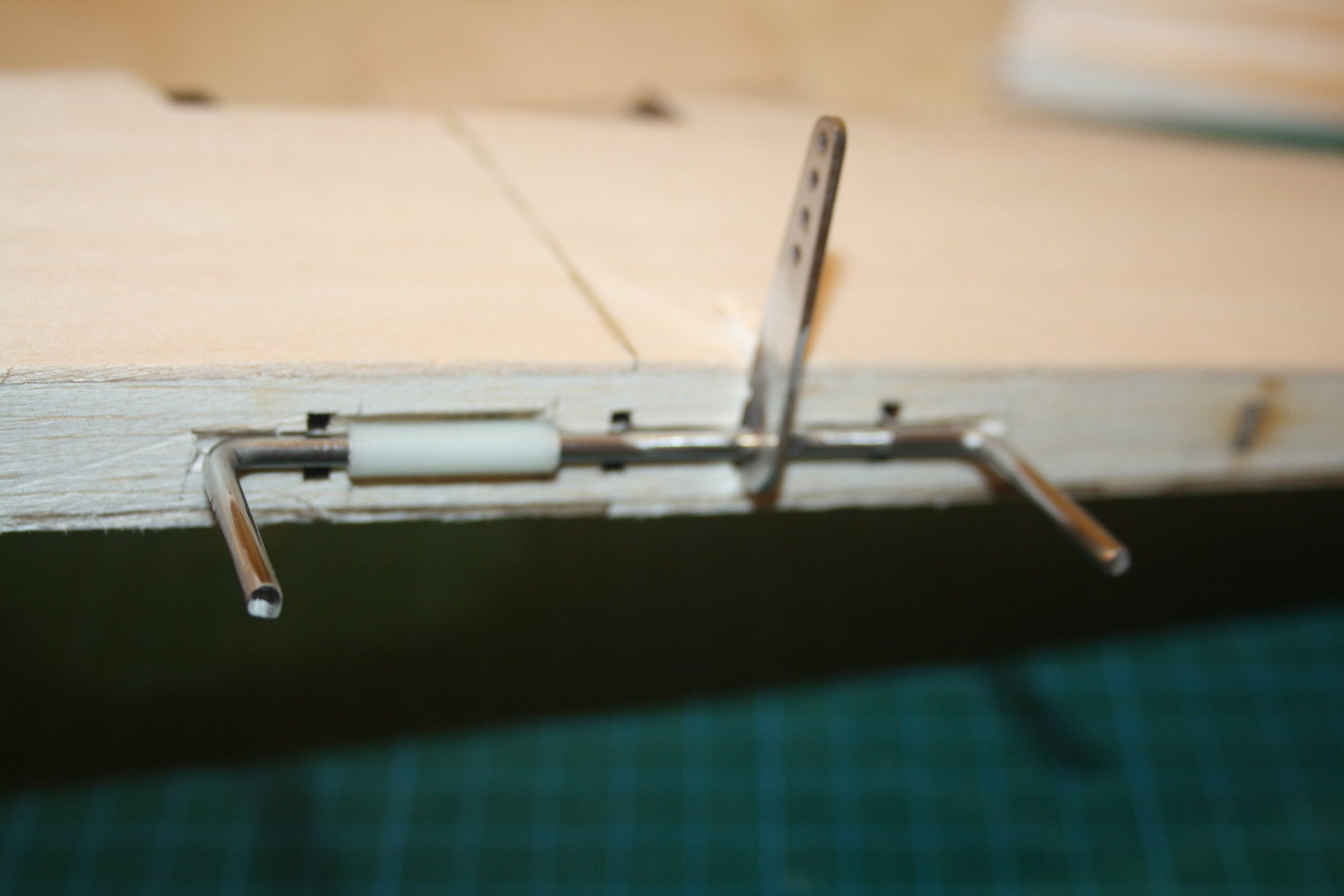
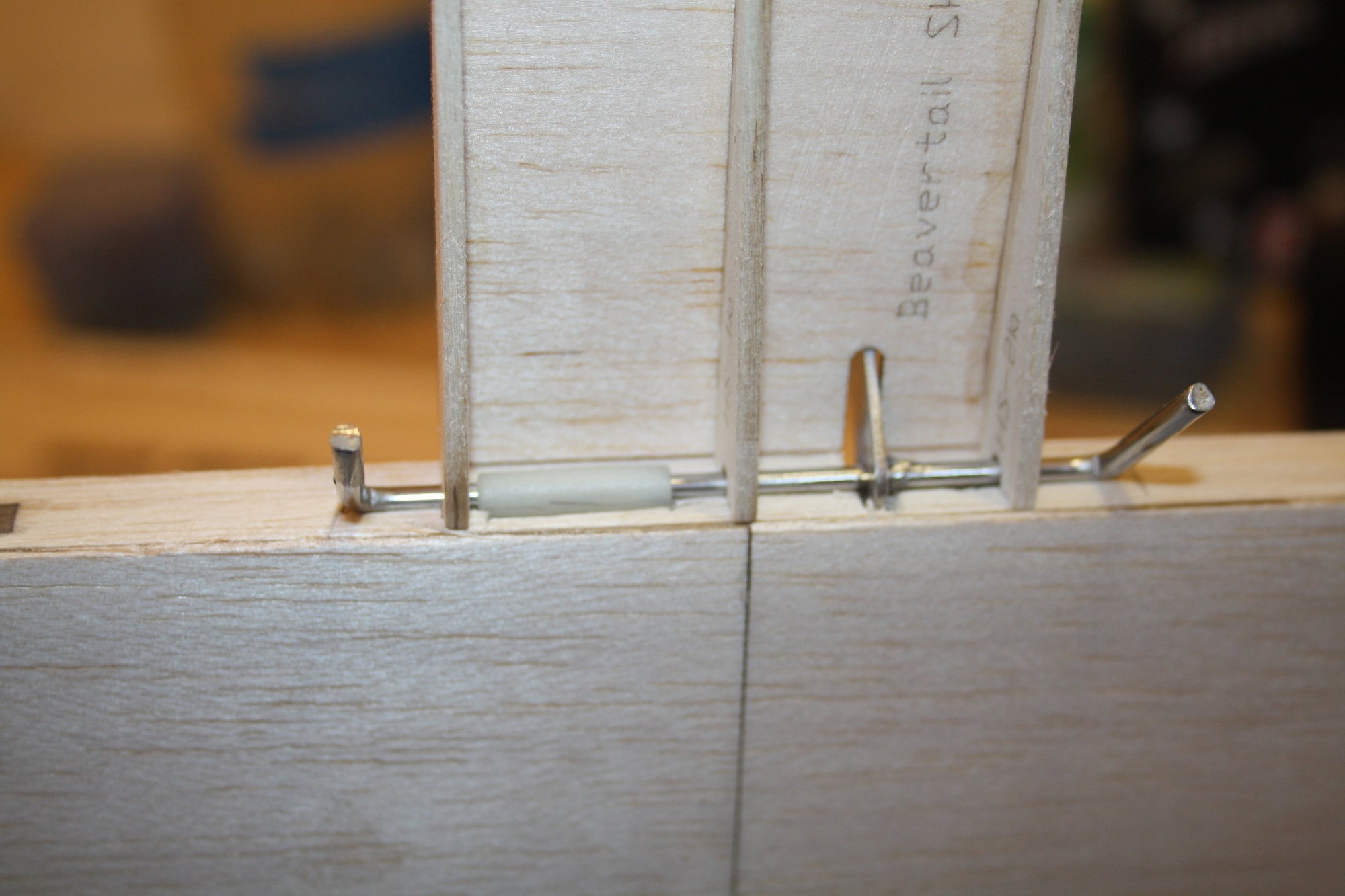
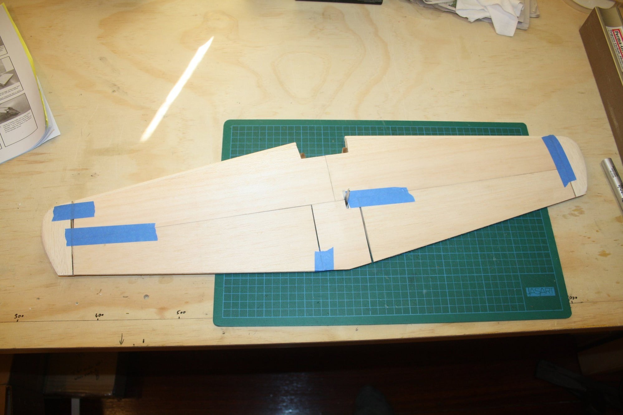
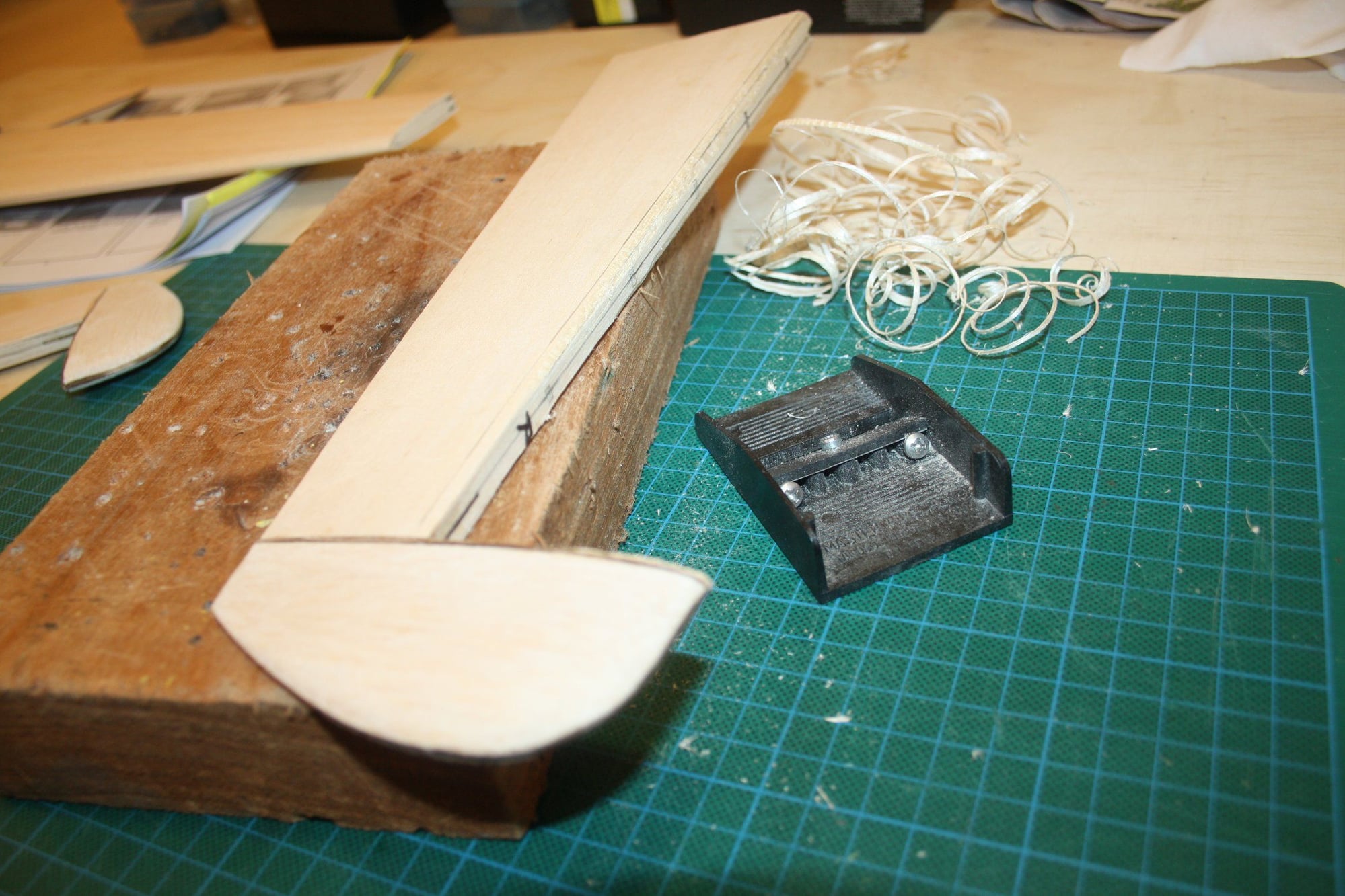
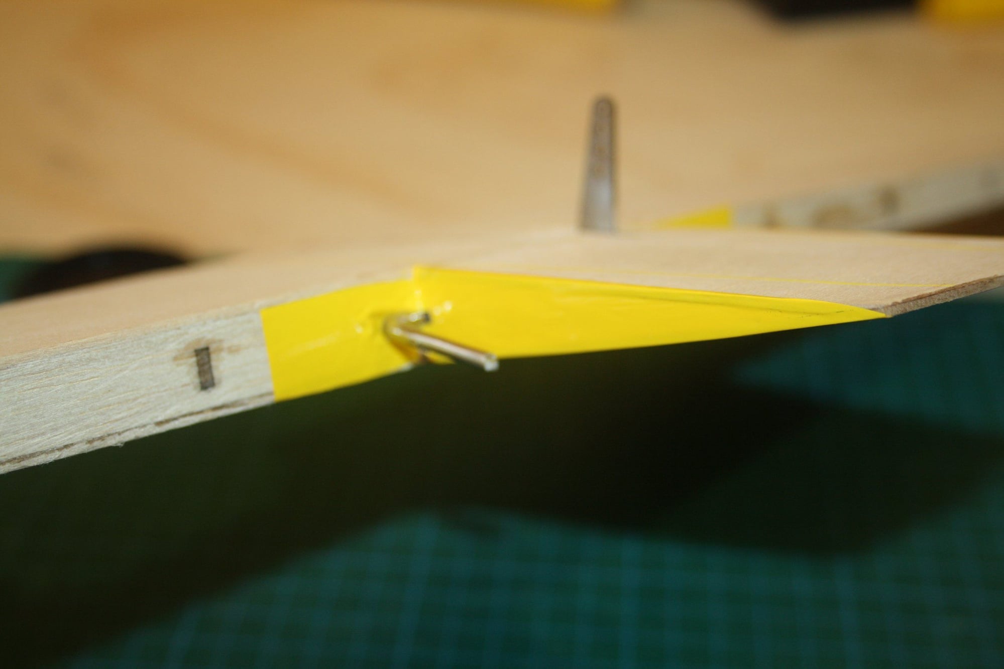
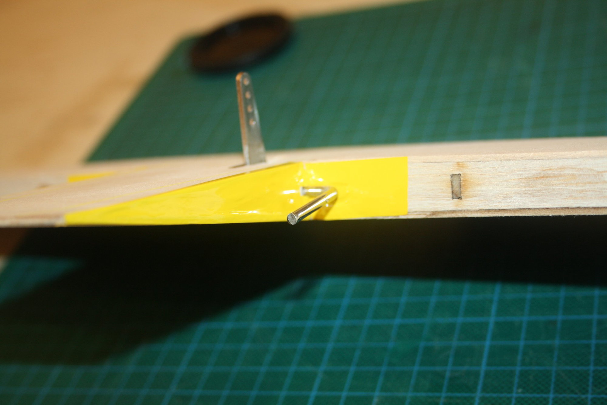
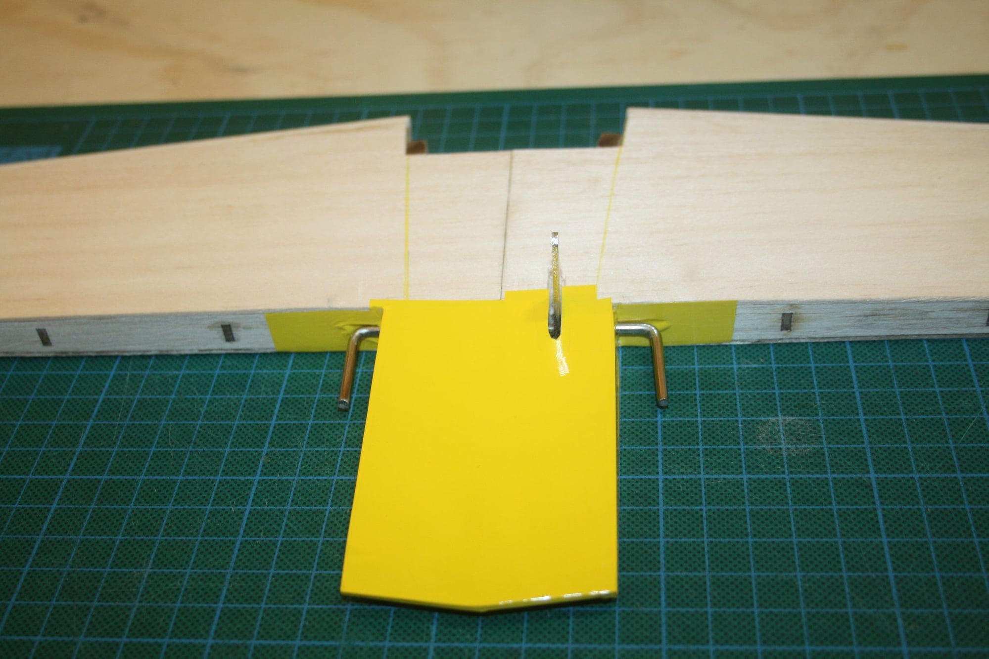
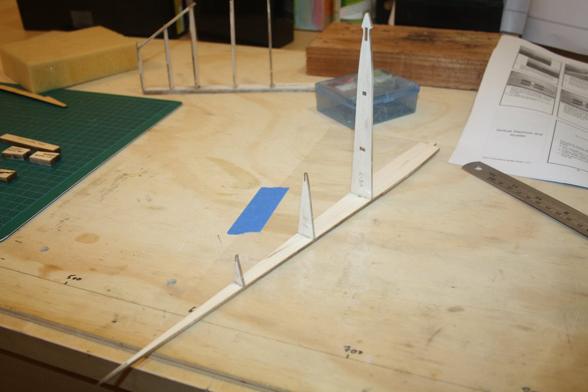
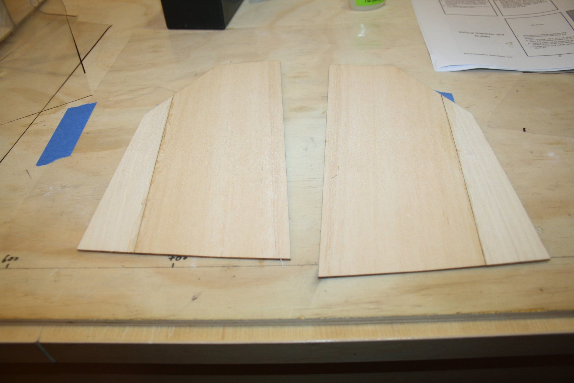
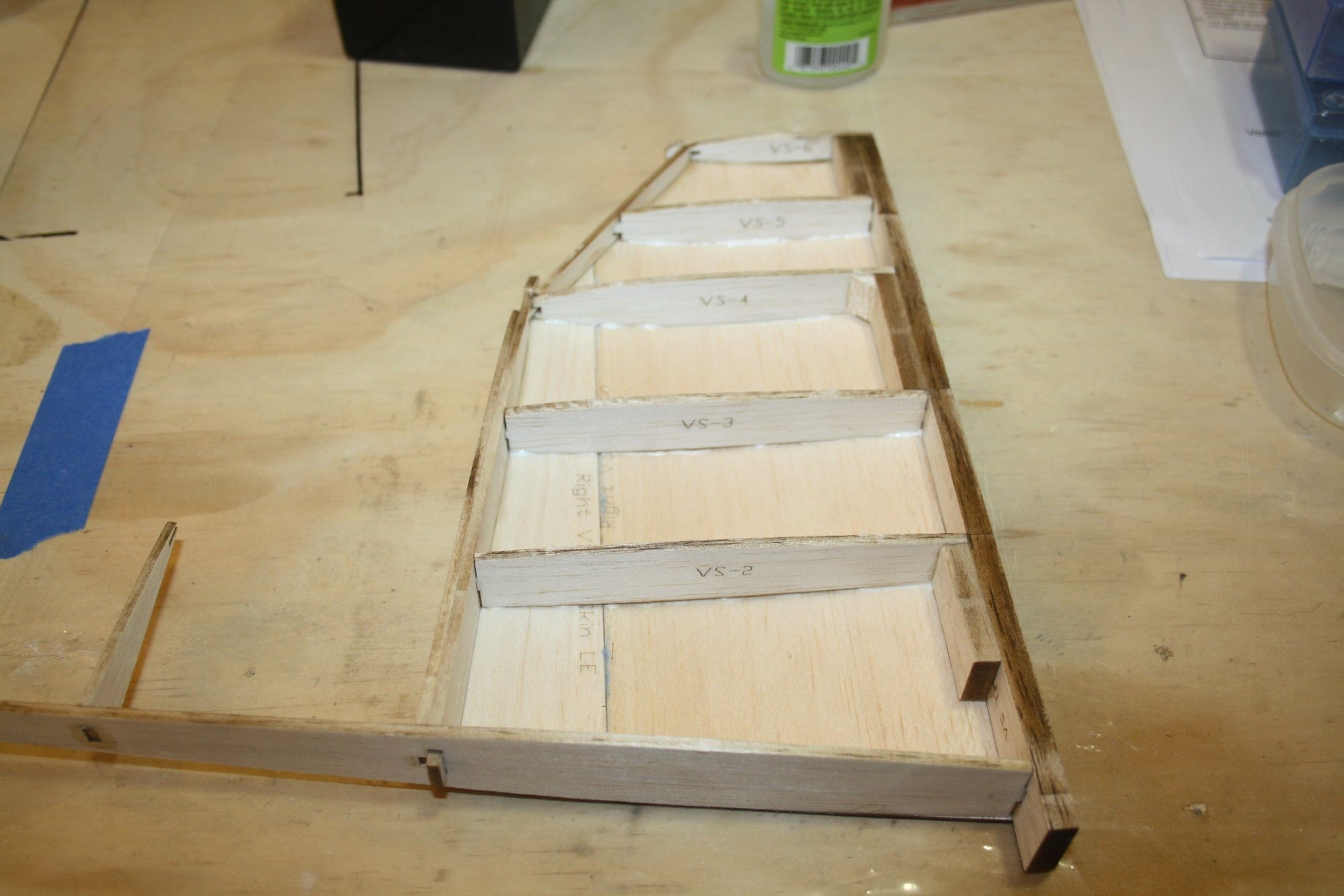
More work on the vertical stabiliser. Note the balsa blocks glued to the TE to provide material for the hinges to be glued into.
The sheeting is again laser cut pieces and the fit was very good.


Cheers,
Eran
The sheeting is again laser cut pieces and the fit was very good.
Cheers,
Eran