BUSA 1/4 scale L-4 build
 09-07-2022, 03:51 PM
#1
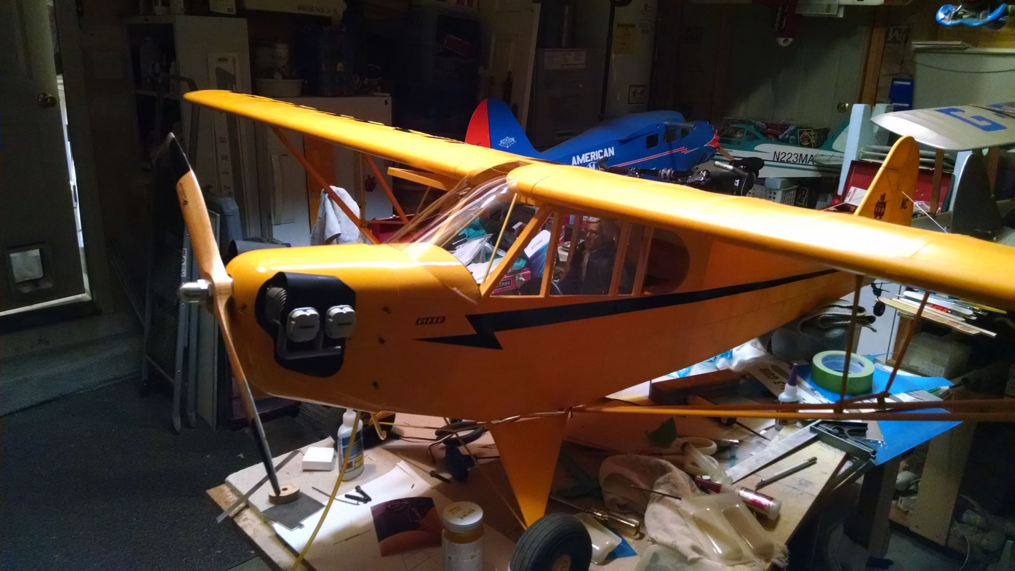
I hope I haven't bitten off more than I can chew here. It's been almost 14 years since I last built a model airplane. But, I'm giving it my best shot, and don't plan to hurry. I bought this kit at a club swap meet around 2005; the plans are yellowed and the instructions read like you already know what to do (they don't tell you much). I contacted BUSA and ordered a set of plans that allow modification of the J-3 to an L-4. I also got a much-updated instruction manual, it even has pictures ! The original instructions are simple typewritten (remember typewriters?) pages stapled in the corner. The new plans are the same in all respects to the originals, except in the construction of the upper fuselage and cabin roof.
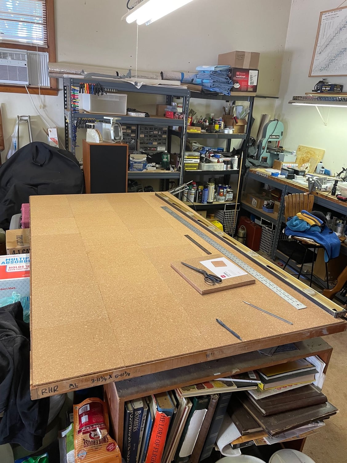
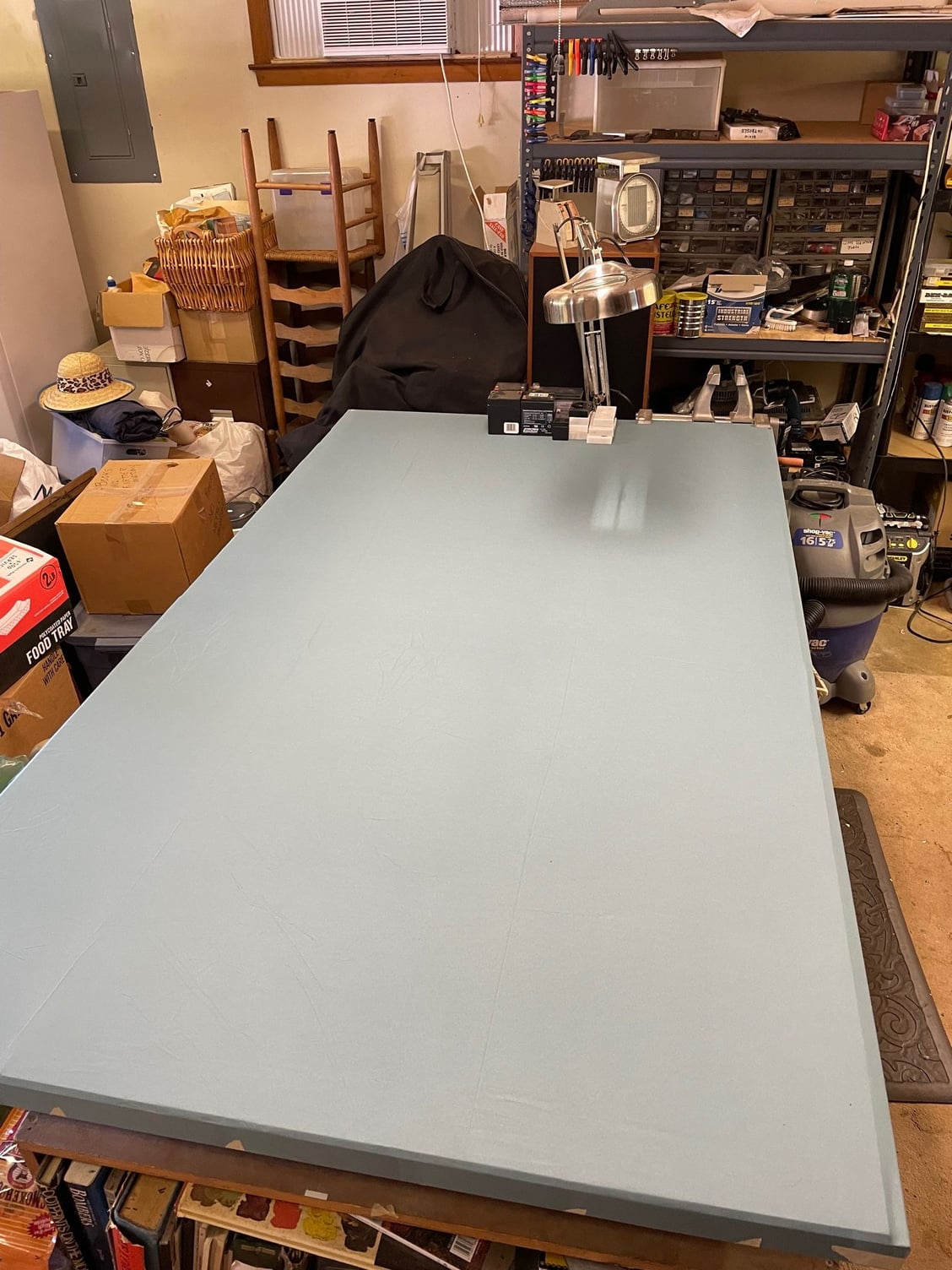
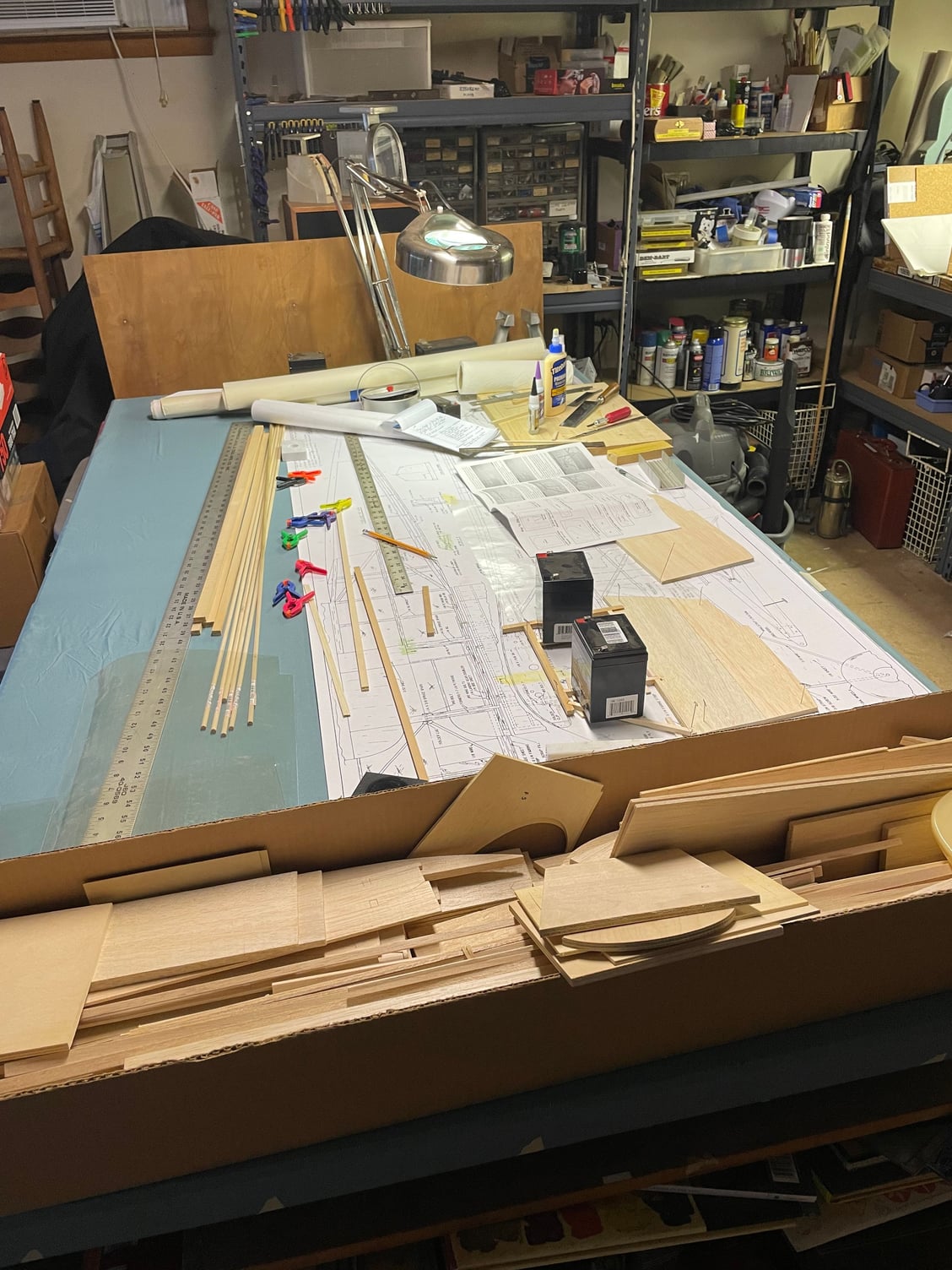
I've been collecting supplies revising my building table and reading the instruction manual and plans for several weeks now, both to familiarize myself with the construction and to build the nerve to start cutting and gluing stuff together. First, my building table. I have an old office desk in my garage, I set it up on cinder blocks to make it taller. On top of the desk lies a large door; I used to work in a hospital O.R., and during a renovation, managed to grab this door, which was going to be disposed of. It's four feet wide and seven feet long, and takes two people to lift it because it has a 1/8" layer of lead sheet in the center. When I was building years ago, I had a piece of black house sheathing on top, which allowed me to pin things down. That is long gone, and this time around, I decided to cover the top in cork. I found 1 foot square pieces of cork 5/32" thick and used spray adhesive to "pave" the tabletop with them. Then I covered the whole thing with an old bedsheet, pulled it tight and stapled it around the perimeter of the table. It cleans off easily, allows things to more easily be slid than directly on the cork. I roll the plans out over all that, and then use wax paper over the plans when I glue things together. I like this big table, I can get to both long sides easily. I plan to build both wing halves at the same time, so I can make them identical and not worry about forgetting something on one side.
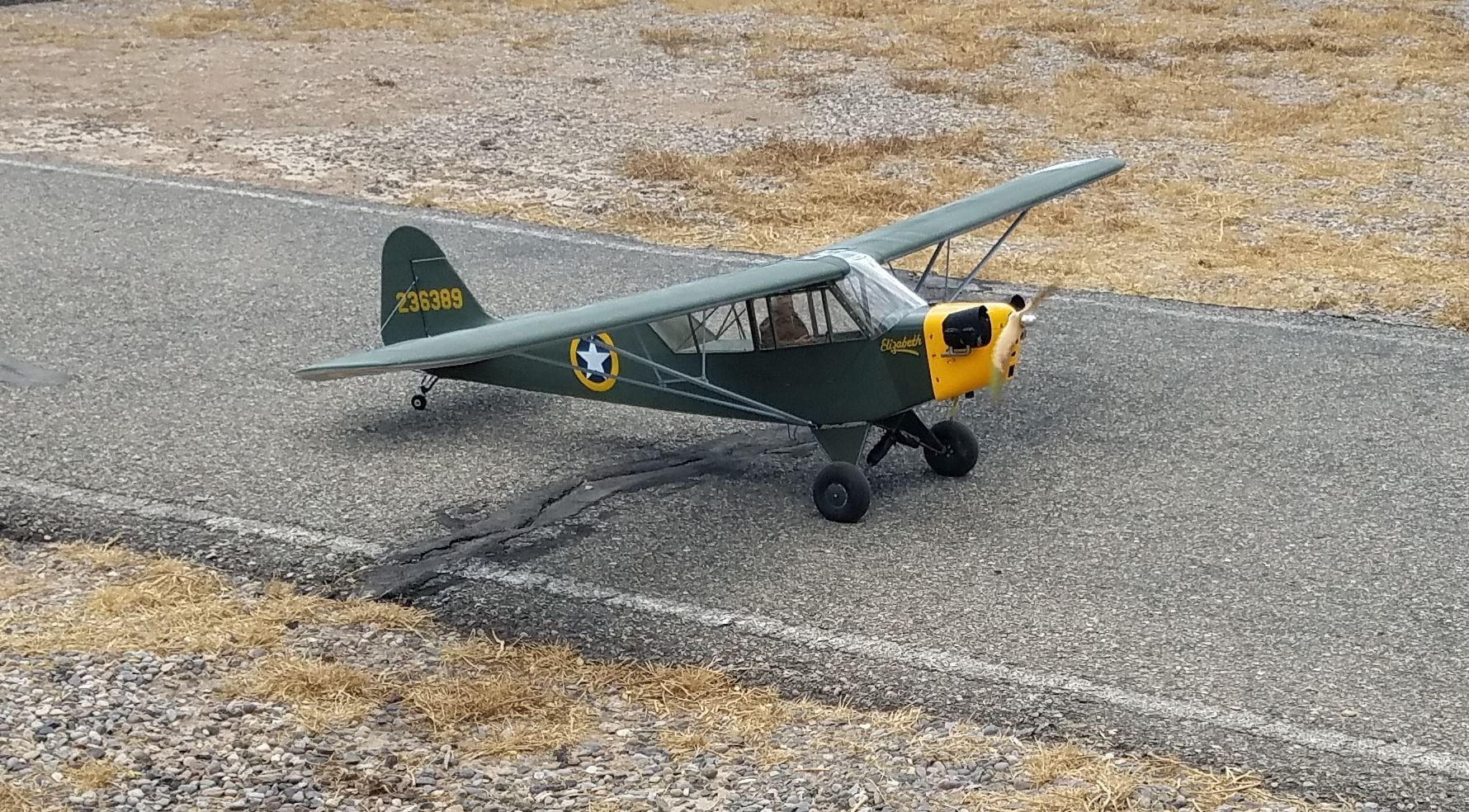
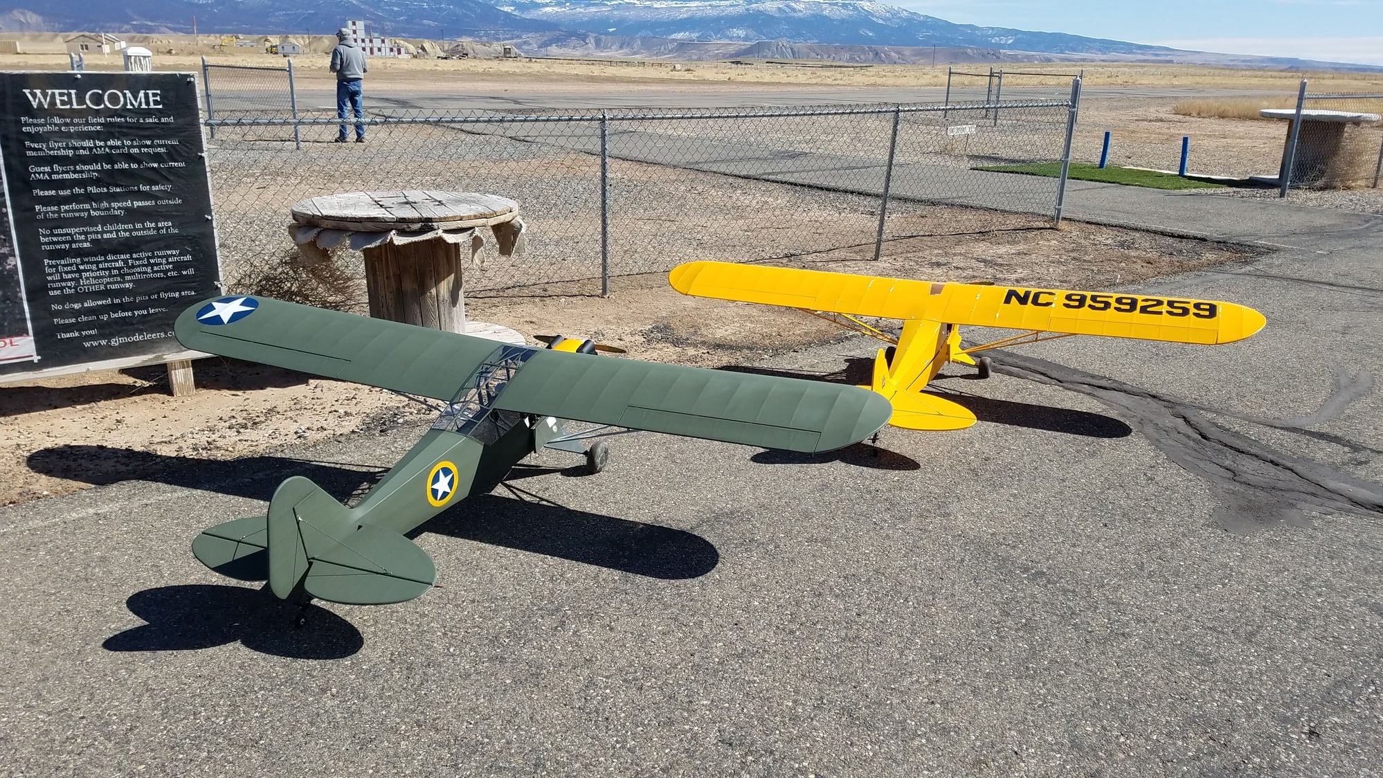
My goal is to build this as a flyable model, but with a much greater level of detail, enough that it can be used as a display in a museum, which is why I'm building it. When finished, it will be donated to our local aviation museum. I have no intentions of flying it myself; I sold all my flight equipment years ago and don't intend to replace any of it. It will be covered in Koverall, doped and painted. I've covered most of my models in the past in Koverall and am very familiar with it. I'm not completely sure how I'll "decorate" it, if I can find historical information on a North Carolinian who flew an L-4 during WWII and pictures, I'll honor him with it. Otherwise, I'll probably make it as "Rosie The Rocketer", an L-4 which mounted 6 recoilless rocket launchers (Bazookas) and was credited with blowing up at least one German tank. I have quite a few pictures of that to detail by.
Feel free to chip in with advice and questions and suggestions. Now for a few pictures.
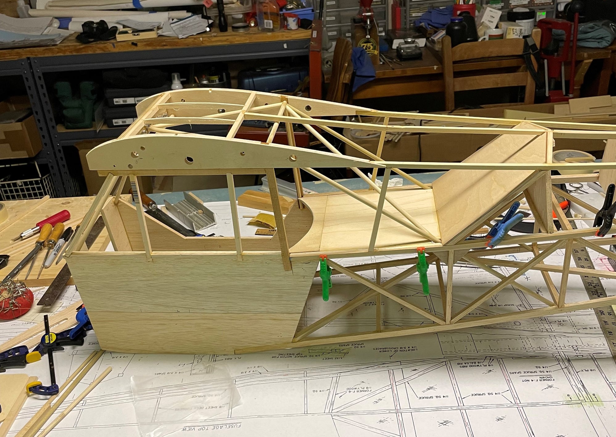
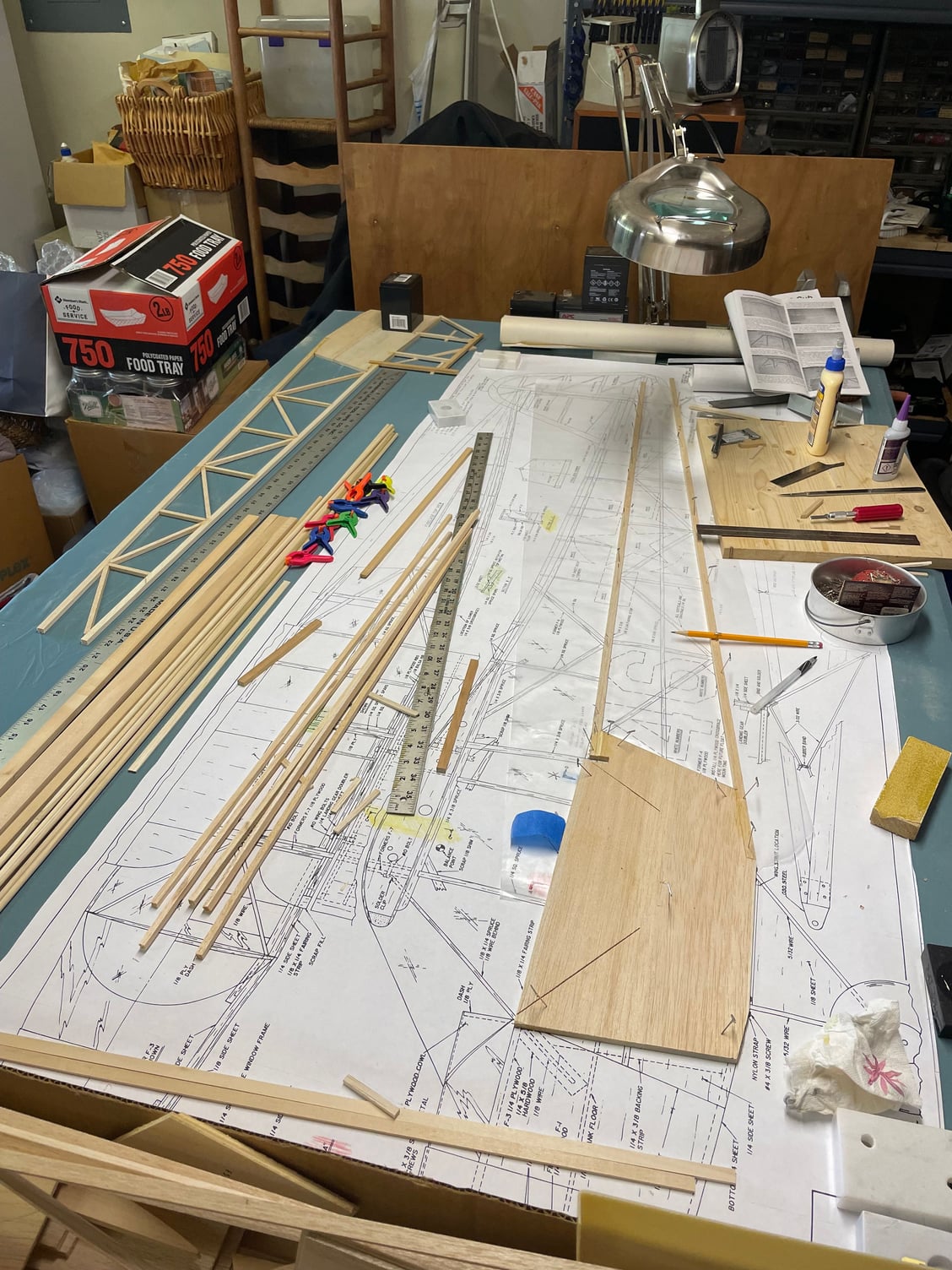
Pardon the mess, this work area gets a lot of use. I also do stained glass, reload ammunition for all my firearms, do some airbrush painting (not very good yet), but the table is now reserved for this build.
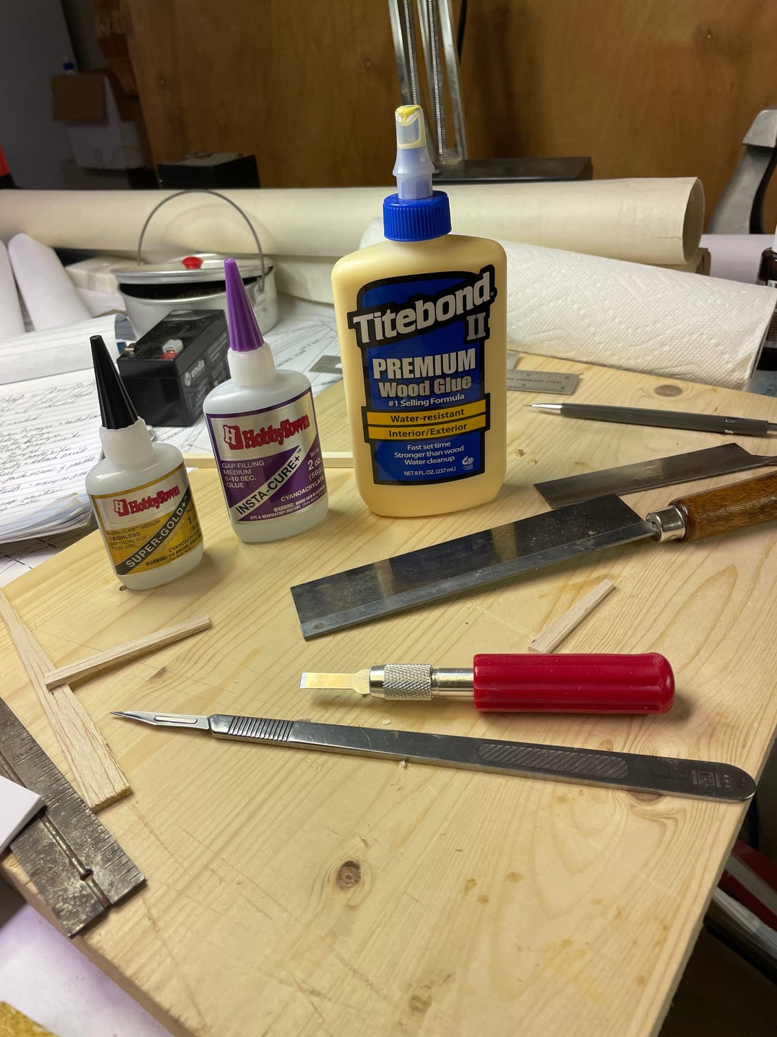
These are the glues I'll use. BUSA encourages using CA glues, but sometimes when I need more working time, I'll use the wood glue.
Big box of sticks, a plan, and already have a mess going:
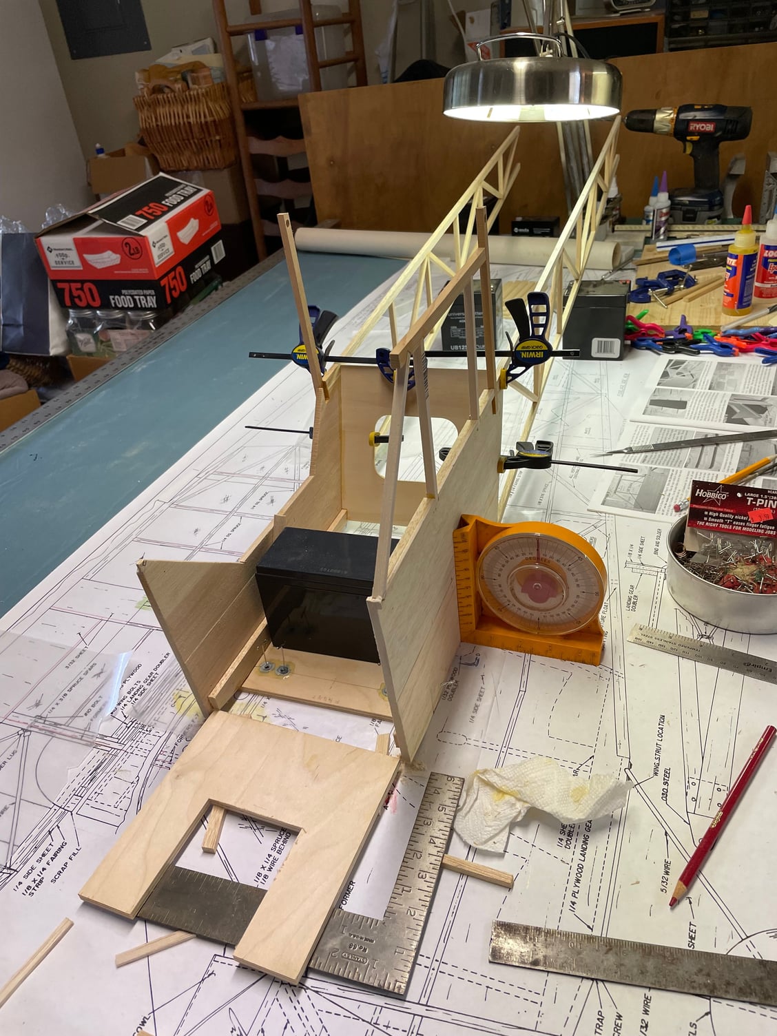
The instructions start you on the cabin sides. In addition to T-pins, I have several old burglar alarm system batteries to hold stuff down, as well as some pieces of marble that used to be the bases of my daughters' dance trophies.
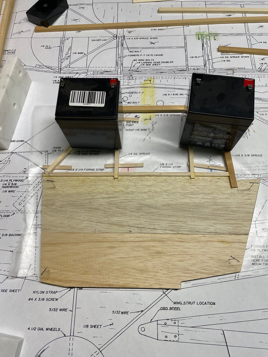
The wire landing gear won't get used, I have a set of Robart gear for this. Does anyone have a suggestion for a scale tailwheel supplier?
More to come, stay tuned.
I've been collecting supplies revising my building table and reading the instruction manual and plans for several weeks now, both to familiarize myself with the construction and to build the nerve to start cutting and gluing stuff together. First, my building table. I have an old office desk in my garage, I set it up on cinder blocks to make it taller. On top of the desk lies a large door; I used to work in a hospital O.R., and during a renovation, managed to grab this door, which was going to be disposed of. It's four feet wide and seven feet long, and takes two people to lift it because it has a 1/8" layer of lead sheet in the center. When I was building years ago, I had a piece of black house sheathing on top, which allowed me to pin things down. That is long gone, and this time around, I decided to cover the top in cork. I found 1 foot square pieces of cork 5/32" thick and used spray adhesive to "pave" the tabletop with them. Then I covered the whole thing with an old bedsheet, pulled it tight and stapled it around the perimeter of the table. It cleans off easily, allows things to more easily be slid than directly on the cork. I roll the plans out over all that, and then use wax paper over the plans when I glue things together. I like this big table, I can get to both long sides easily. I plan to build both wing halves at the same time, so I can make them identical and not worry about forgetting something on one side.
My goal is to build this as a flyable model, but with a much greater level of detail, enough that it can be used as a display in a museum, which is why I'm building it. When finished, it will be donated to our local aviation museum. I have no intentions of flying it myself; I sold all my flight equipment years ago and don't intend to replace any of it. It will be covered in Koverall, doped and painted. I've covered most of my models in the past in Koverall and am very familiar with it. I'm not completely sure how I'll "decorate" it, if I can find historical information on a North Carolinian who flew an L-4 during WWII and pictures, I'll honor him with it. Otherwise, I'll probably make it as "Rosie The Rocketer", an L-4 which mounted 6 recoilless rocket launchers (Bazookas) and was credited with blowing up at least one German tank. I have quite a few pictures of that to detail by.
Feel free to chip in with advice and questions and suggestions. Now for a few pictures.
Pardon the mess, this work area gets a lot of use. I also do stained glass, reload ammunition for all my firearms, do some airbrush painting (not very good yet), but the table is now reserved for this build.
These are the glues I'll use. BUSA encourages using CA glues, but sometimes when I need more working time, I'll use the wood glue.
Big box of sticks, a plan, and already have a mess going:
The instructions start you on the cabin sides. In addition to T-pins, I have several old burglar alarm system batteries to hold stuff down, as well as some pieces of marble that used to be the bases of my daughters' dance trophies.
The wire landing gear won't get used, I have a set of Robart gear for this. Does anyone have a suggestion for a scale tailwheel supplier?
More to come, stay tuned.
Last edited by khodges; 09-07-2022 at 04:03 PM.

The following users liked this post:
khodges (09-07-2022)
09-07-2022, 06:00 PM
#3
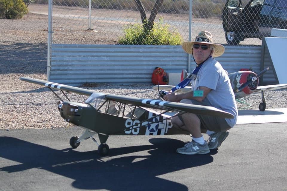
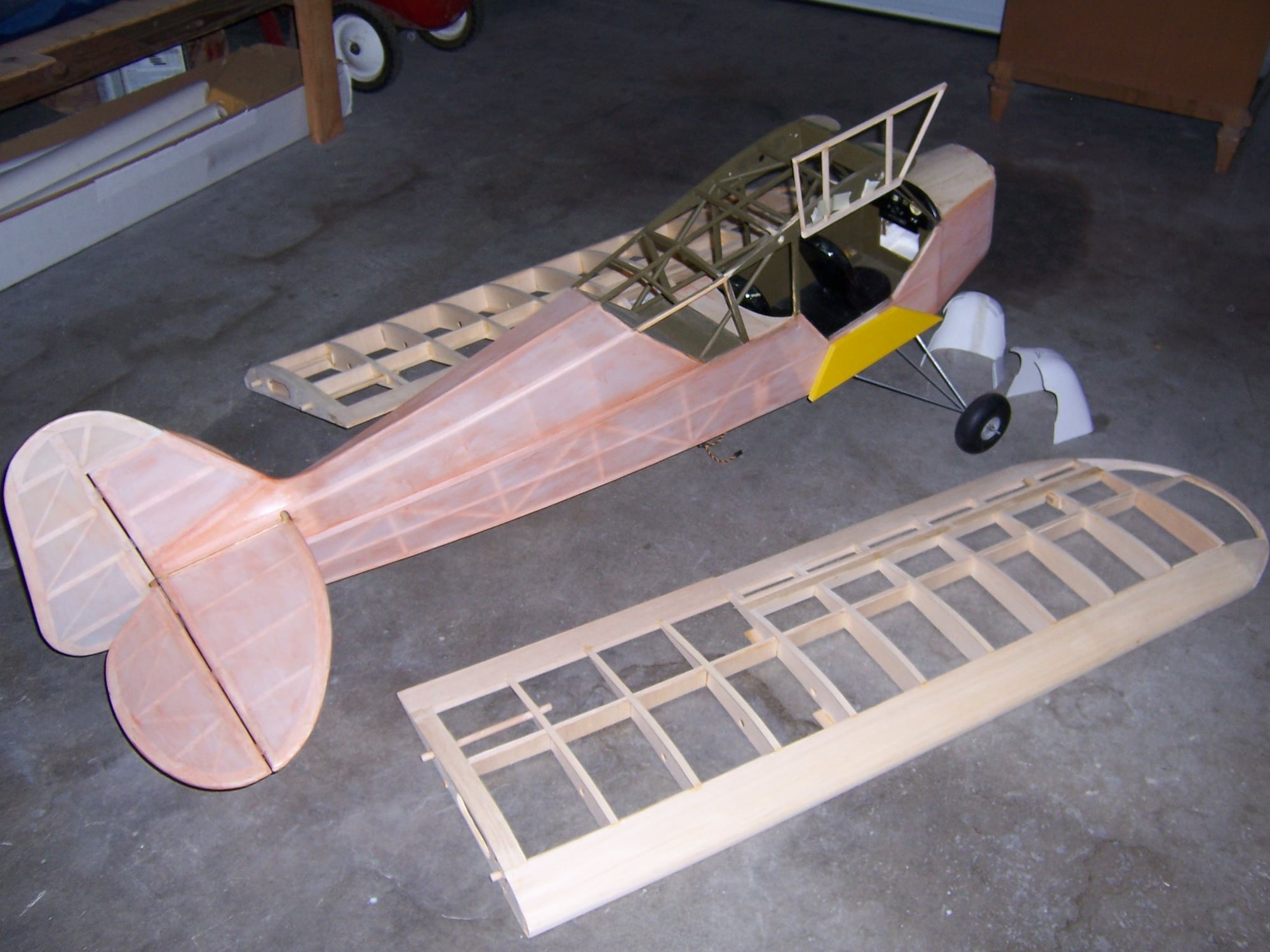
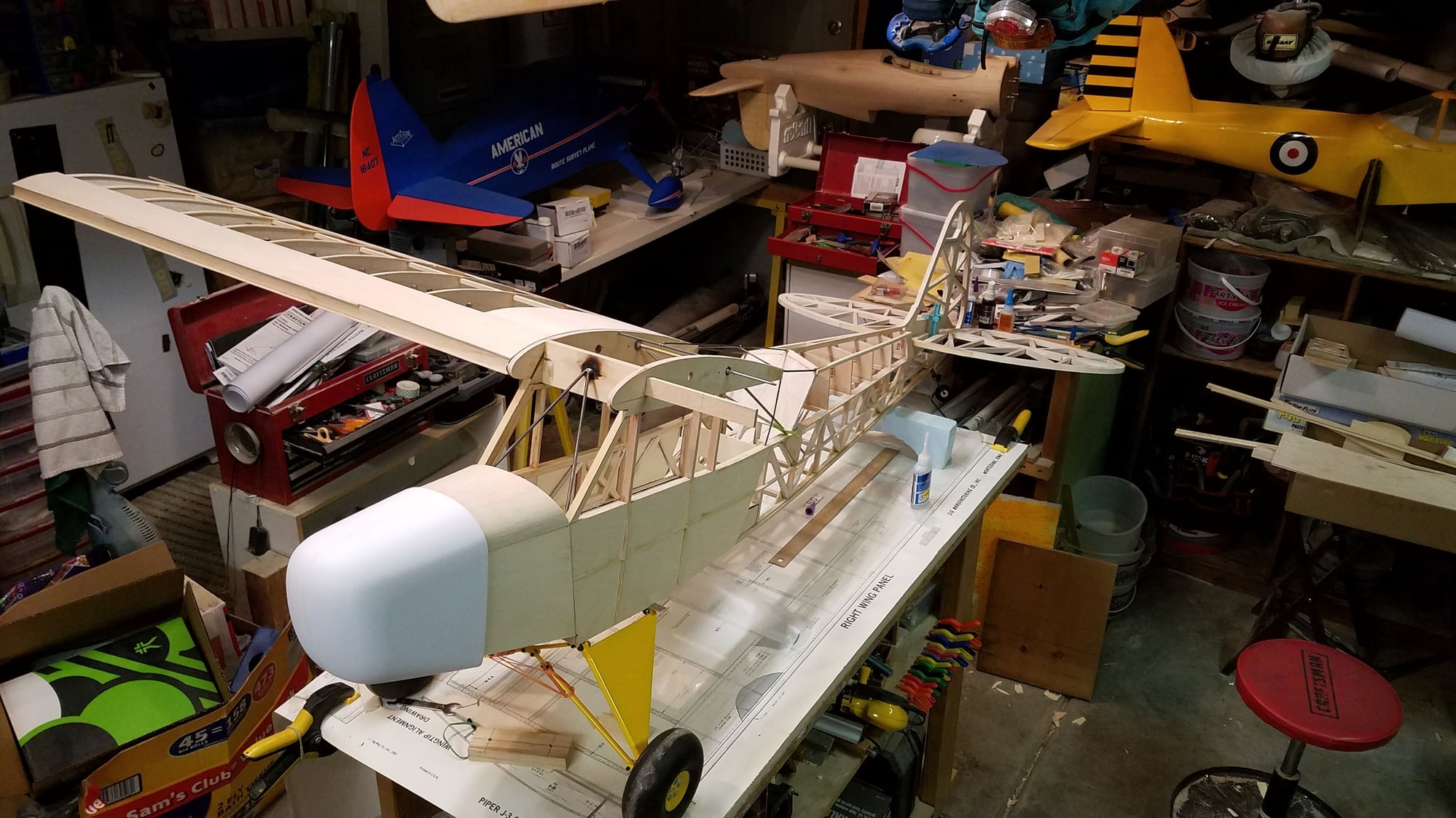
Great-looking airplane, Jerry!! Hoping mine will look a lot like that when it's done. Can you take a picture of the top of the wing center so I can see how you supported the wing while adding the full greenhouse? Or did you build it per BUSA's plan? They do a nice job on the greenhouse behind the wing, but the plans I have still show a skinned center section of the wing, although it is different from the J-3 version. I have probably a hundred or more detail photos I took of an L-4 at a grass strip about 20 miles from me, and several that were at Oshkosh when I was there in 2008. I don't really care how heavy I build it, but I do plan on some accurate details.
I say I won't fly it, but who knows? The museum is interested in the model, but it will be a couple of years before we have the building and hangar finished. There should be enough room to display it, we have a P-3 Orion to display inside, as well as more than a dozen other aircraft, including the first F-105 off the line, the last F-14 to be retired, an A-6, EA-6B, A-7, OV-1 Mohawk, and the F/A-18 Blue Angels #5 solo that was retired in 2020. Ought to have some good company. I've been volunteering at the museum whenever I can, doing everything from showing and describing the planes we have to visitors, to scraping paint in the restoration hangar. I got to climb all over my favorite jet fighter of all time, an F-4 Phantom, helping to get it ready for a new paint job.
I never was as good a pilot as I was a builder, although you have to be pretty bad to not be able to fly a Cub. I did manage to stall-spin my 1/5 scale L-4 I had back then, and the frustration of that was part of the reason I quit flying R/C. If I do prep this one to fly, I have to decide whether to go gas or electric. I like a plane to sound like a plane, so I'll probably do gas, but electric is so much cleaner, and batteries and motors have markedly improved since I last flew.
09-07-2022, 07:25 PM
#4

Sounds like fun, I built a sig into an L-4 a couple of years ago, used music wire to frame the cabin, and covered it bit3h brass strip soldered together for a more open greenhouse.
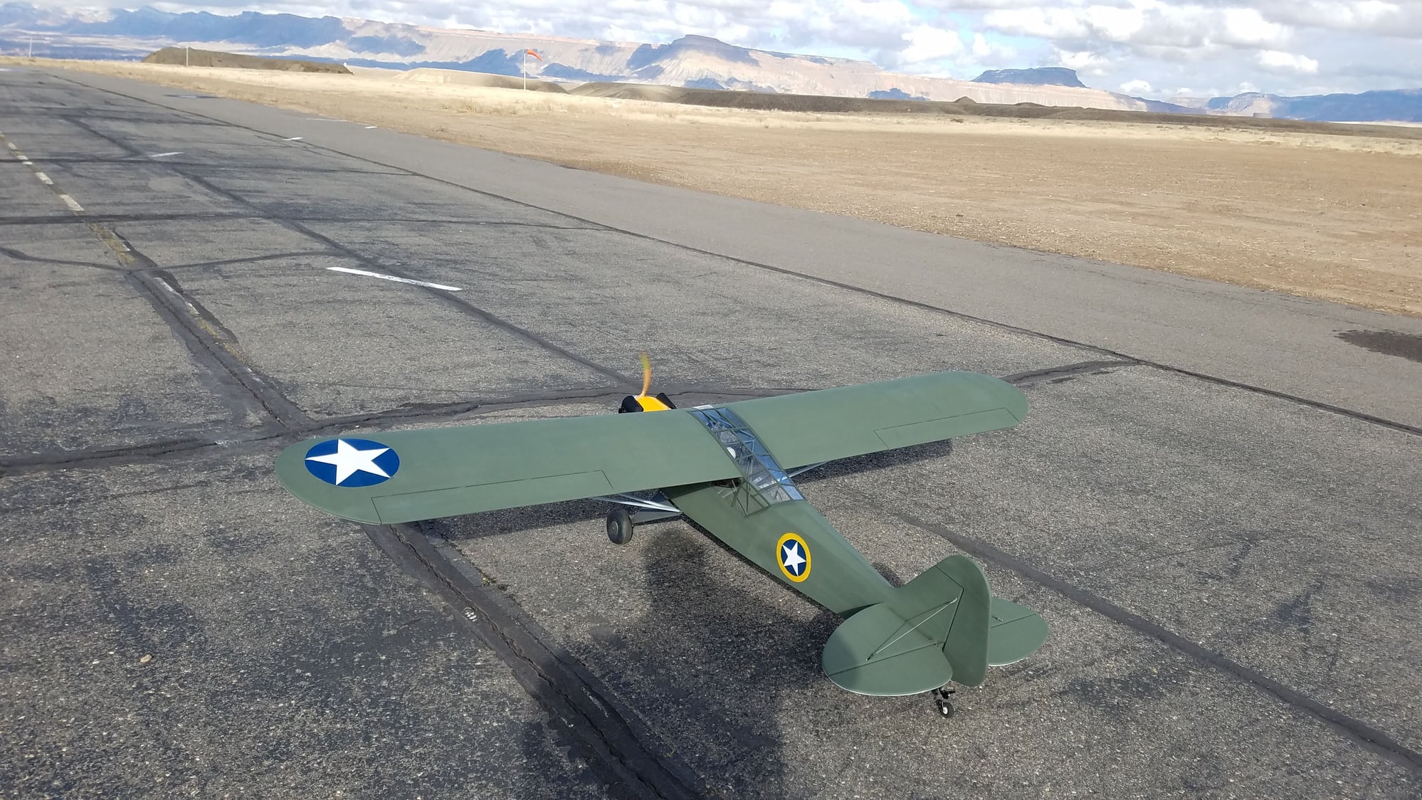
also covered with Koverall and then painted with krylon
hopefully these pictures may give you some ideas
also covered with Koverall and then painted with krylon
hopefully these pictures may give you some ideas
The following users liked this post:
khodges (09-08-2022)
09-08-2022, 04:38 AM
#5
Sounds like fun, I built a sig into an L-4 a couple of years ago, used music wire to frame the cabin, and covered it bit3h brass strip soldered together for a more open greenhouse.
also covered with Koverall and then painted with krylon
hopefully these pictures may give you some ideas
also covered with Koverall and then painted with krylon
hopefully these pictures may give you some ideas
 ,I have much the same in mind for my build, brass tubing and wire, to keep the bulk down and make it look as scale as possible. I like how you gusseted the joints in the fuselage, My plans are to glue up the structure then drill the joints and glue in toothpicks across them for more strength, and to use spruce sticks for the longerons instead of balsa. How much weight did that greenhouse add? I know the Cub has so much wing you can afford to build heavier, and still get away with a relatively small engine and retain good flight characteristics. I powered my 1/5 scale Sig L-4 with a .65 Saito turning a 14" (scale diameter) prop, and it had plenty of power.
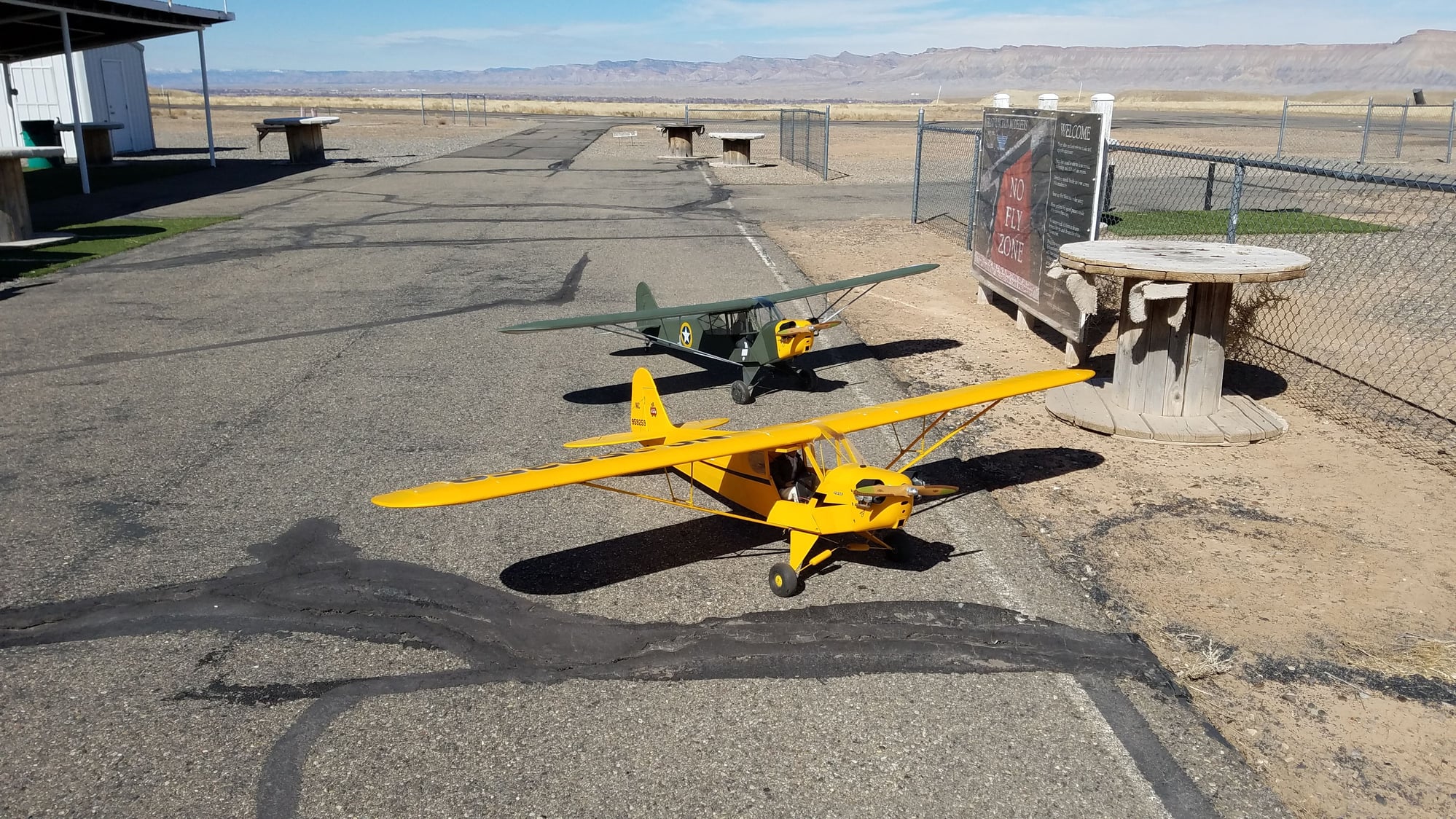
I also love the paint scheme you used, with the old style circled star. Where in the world is your flying field, not a chance of a tree-eating airplane anywhere I can see.. Thatnks for those construction pictures, I plan to study them closely.

 09-08-2022, 01:29 PM
#8
My Feedback: (14)
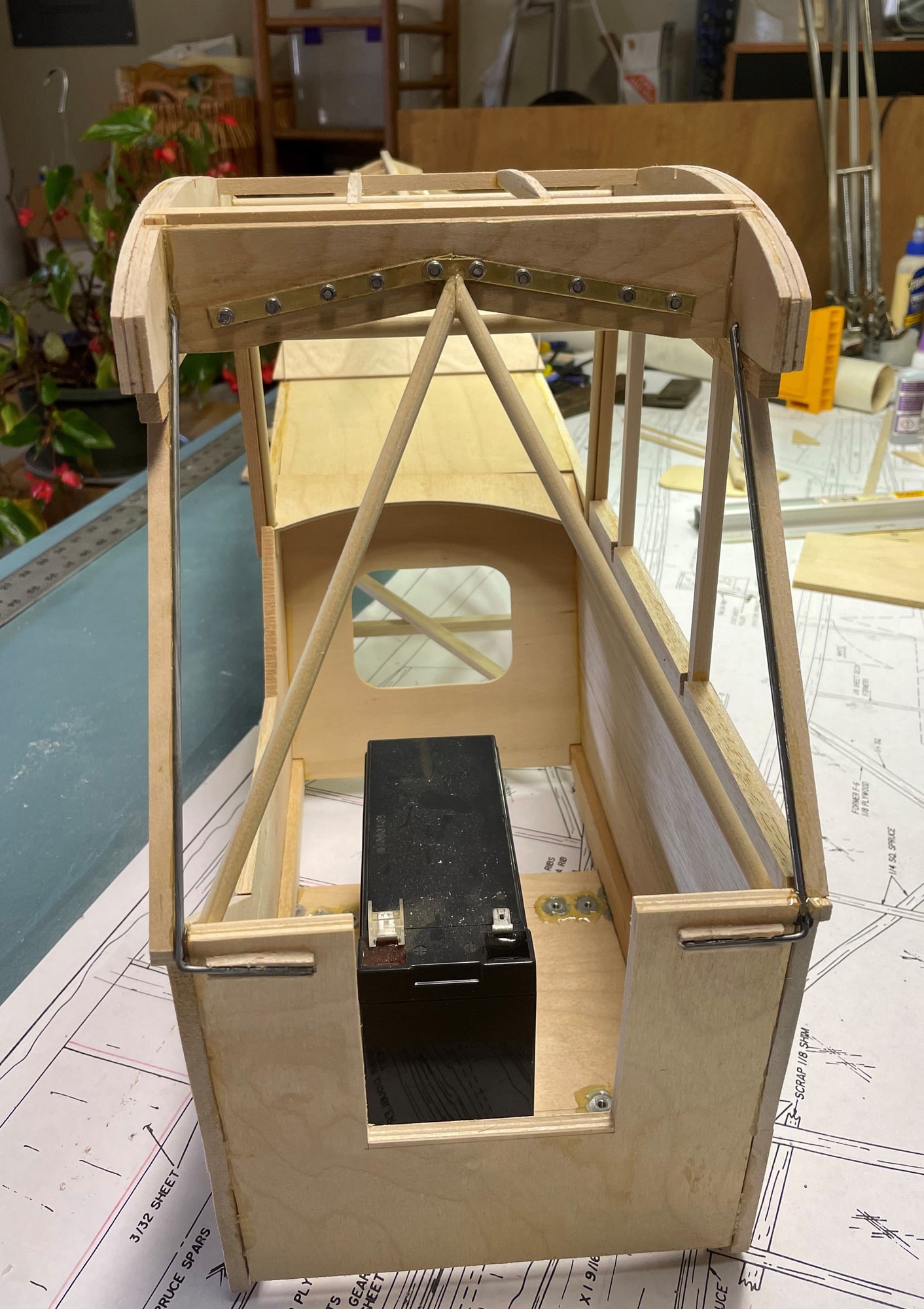
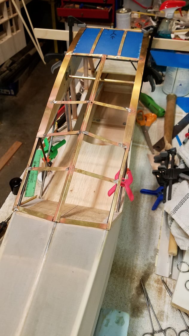
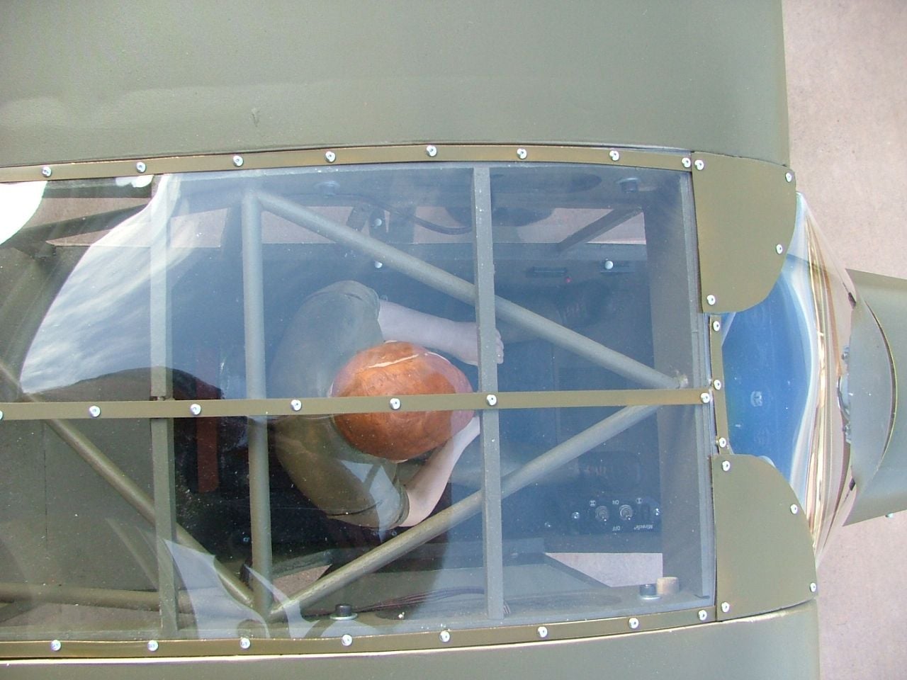
What I did was dowels in the wing that stick out just the thickness of the fuselage sides, so dowels into matching holes in the fuse "ribs" and then bolts from the inside of the fuselage into blind nuts in the wing root rib. You can see the dowel ends sticking out of the wing root ribs in this picture.
09-08-2022, 01:34 PM
#9
My Feedback: (14)
If you look closely at this pic you can see the heads of the 2 allen bolts that hold the wing halves to the fuse and the ends of the dowels sticking slightly into the fuselage. Struts are VERY functional using this set-up and having good, strong struts in important
09-09-2022, 08:14 AM
#10
Jerry, that's almost exactly how I built my 1/5 scale version years ago, but you did a much better job than I. My 1/5 scale was a real learning experience, and I purposely overbuilt it because I wasn't sure whether it would have been strong enough. I'm leaning towards doing the center section "tubing" like you have done, using wood dowels. A diagram I have from a Cub (fullscale) rebuilder site shows fuselage tubing sizes, which vary from 5/8" to 1" depending on the location; there are also varying wall thickness of the tubing, but that doesn't play into modelling in scale. There is only one spot that uses 1" and that is the main spar attach point, most of the rest of the "trapeze structure in the roof is 7/8", with the cabin uprights being 5/8" and the "A" pillar being 7/8". 1/4" dowels would be one inch at full scale, and I think the difference is negligible for the additional strength needed in a model. I thought of soldering the entire trapeze and cabin tubing in brass, but that comes out very heavy and is easily bent, where wood will flex quite a bit without breaking. I think the uprights, that fall behind the cabin window fame on the left and the door on the right, could be downsized to 3/16" if needed, because there is the wooden window frames for the added strength there. Here is where a static model can be more closely scaled, as it will never see the stresses of flight and need the extra strength. I've seen pictures of modelers building 1/3 scale and half scale using aluminum tubing and TIG welding it, but that would be ridiculous at 1/4 scale and I don't possess those skills anyway.
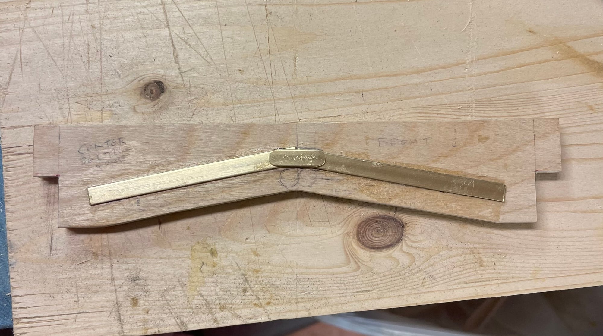
I do know I plan to cut the main spar to look more closely like the full scale Cub, but keep it as one piece. The full size spar extensions meet with a gap and have heavy steel straps that bolt together and to the meeting of the main spar supports and the bottoms of the spar extensions are tapered. I plan to use steel to model the strapping and brackets, which may give enough strength to model the spar join accurately. See the picture below:
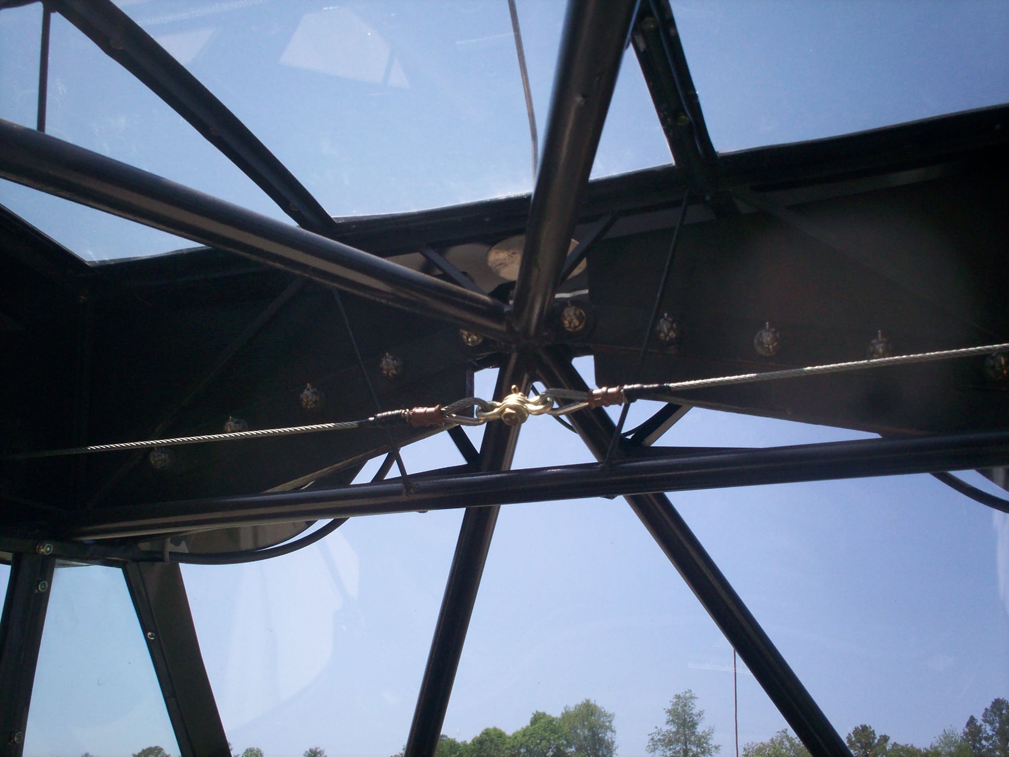
The cable in the picture is the aileron crossover cable and has the fitting that can be disconnected when the wings are removed. I have a front view of this, just can't find it right now.
I do know I plan to cut the main spar to look more closely like the full scale Cub, but keep it as one piece. The full size spar extensions meet with a gap and have heavy steel straps that bolt together and to the meeting of the main spar supports and the bottoms of the spar extensions are tapered. I plan to use steel to model the strapping and brackets, which may give enough strength to model the spar join accurately. See the picture below:
The cable in the picture is the aileron crossover cable and has the fitting that can be disconnected when the wings are removed. I have a front view of this, just can't find it right now.
09-09-2022, 08:23 AM
#11
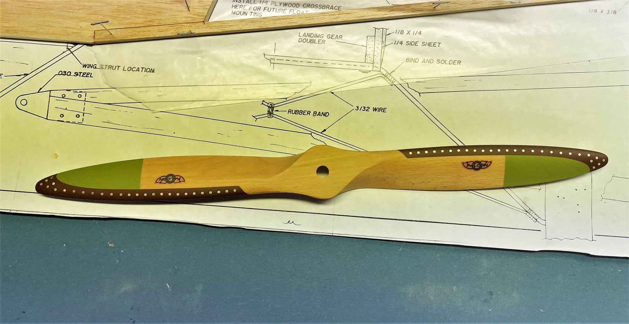
I received the scale propeller I ordered from BUSA; looks really good, but I may apply a brass foil over the painted LE guard to add some detail. I did a couple of display props back in the day that came out pretty good. Here's the BUSA Cub prop:
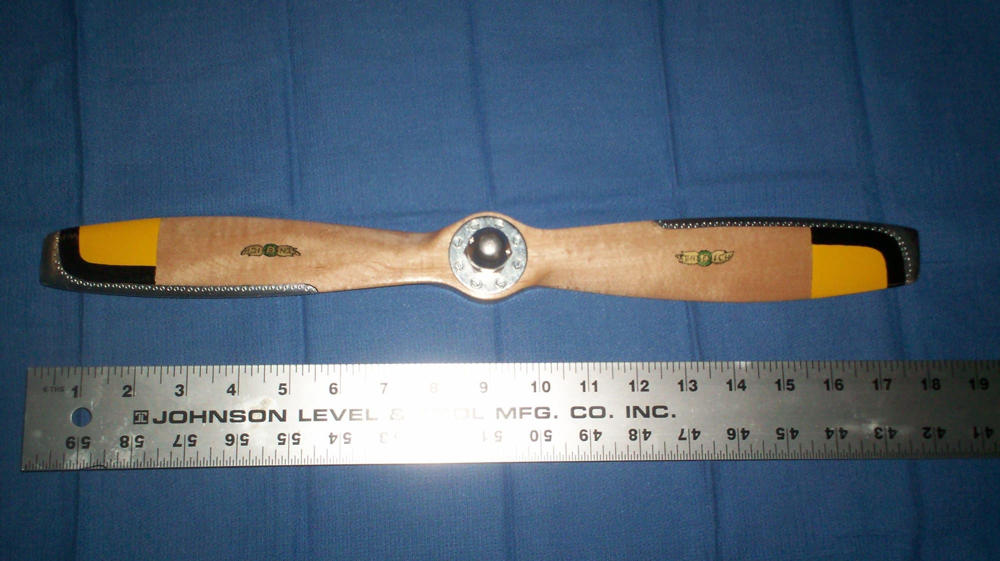
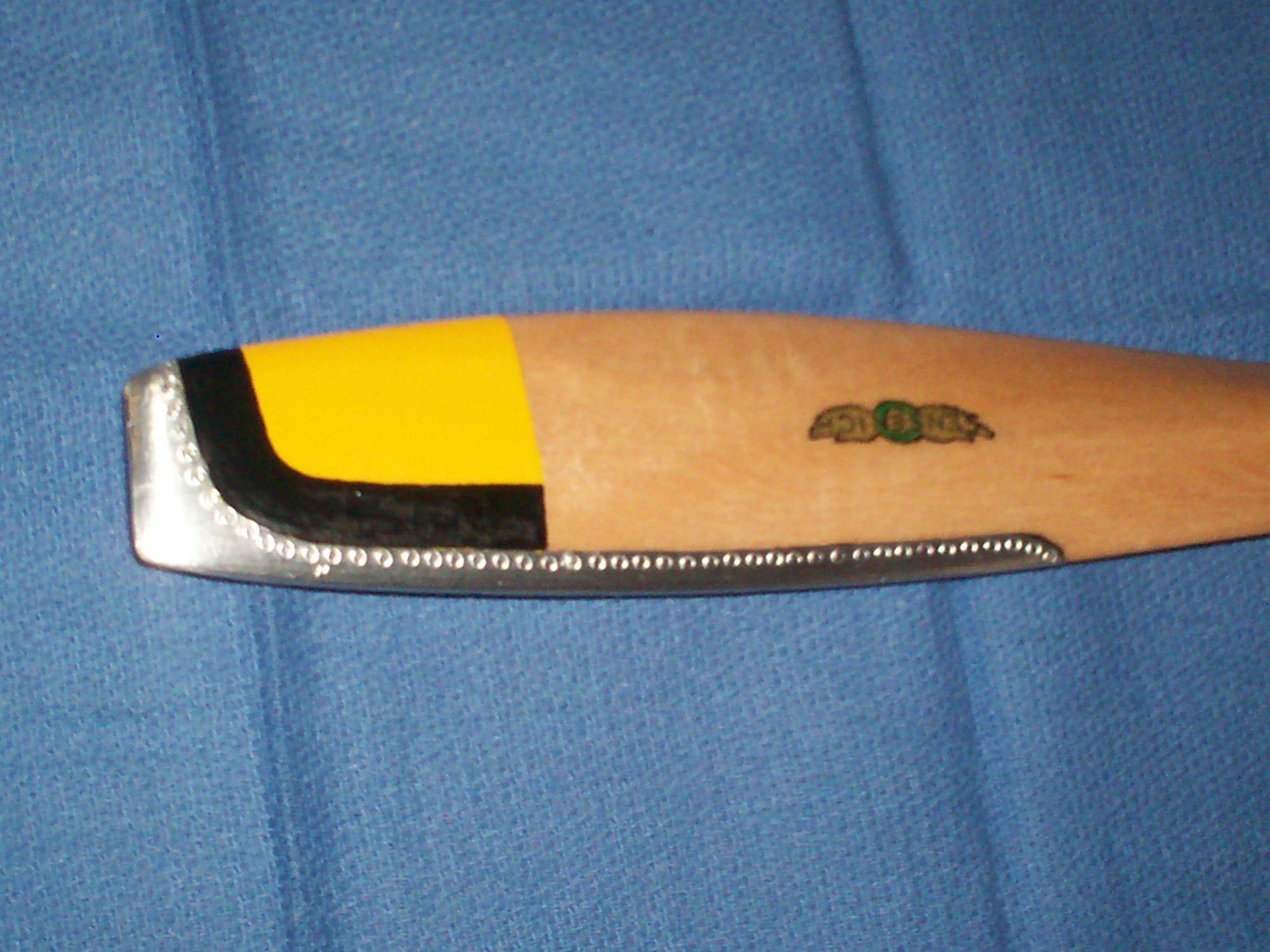
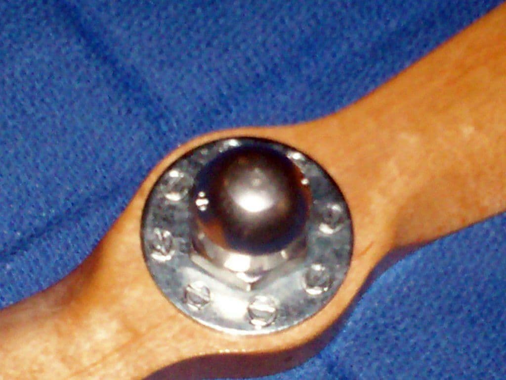
and here is the one I did for a 1/5 scale WACO UMF-3
and here is the one I did for a 1/5 scale WACO UMF-3
Last edited by khodges; 09-09-2022 at 08:28 AM.
 09-10-2022, 01:03 PM
#13
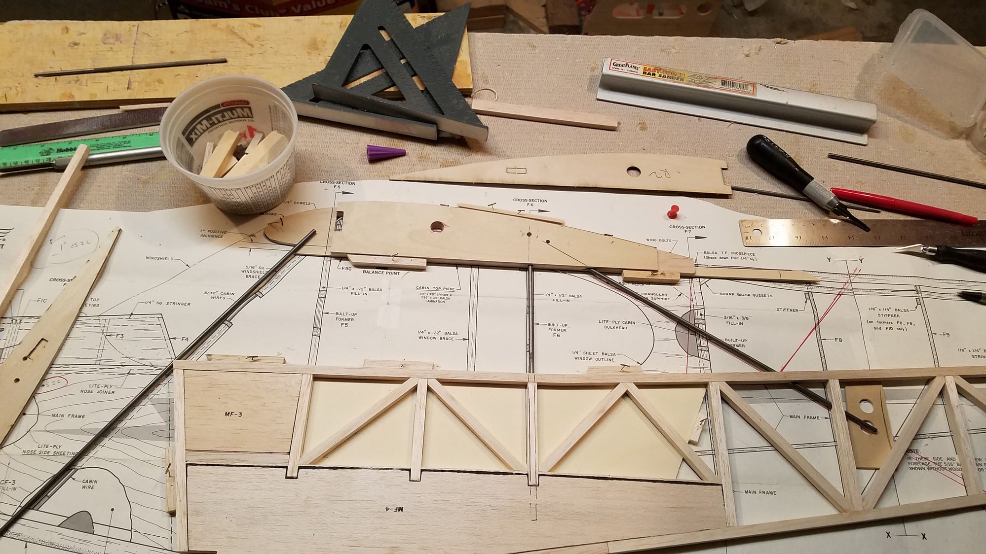
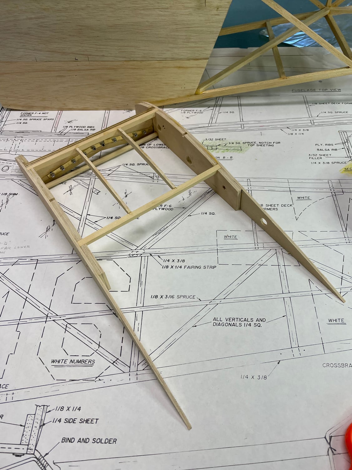
Well, gotta diverge from the plans and manual for a while. I got shorted on my parts; instead of getting a sheet of plywood wing root/fuselage top rib pieces, I got extra wing ribs, of balsa. So, a trip to the local hobby shop for some hobby ply to cut my own. This isn't so bad, really, now I can relocate a couple of holes and delete a couple of notches so I can make the center section closer to the actual configuration.
Buying the plywood was real culture shock. The last hobby ply I bought was about $12.50 for a 1'x2'x1/8" piece of aircraft grade. I paid almost $40 for the exact same thing today, wow. Anyway, got it home, used one of the plywood wing root ribs I did get as a pattern, and traced out replacements, then cut them on my scroll saw. I make my cuts just outside the traced line, then sand to fit. Takes longer but is way more precise. When I get them matched to the pattern, I'll laminate them, and then do a final sanding to fit them exactly on the plans. I'll do my measuring, based on some full-scale photos, and drill holes or cut notches as needed. The main spar will go as per the plan, but there is a round tube just behind and below, plus the cross brace tube where the rear spar on the plan is. When this is all added when the fuselage frame gets boxed together, it will hold things together while more scale bracing is added.
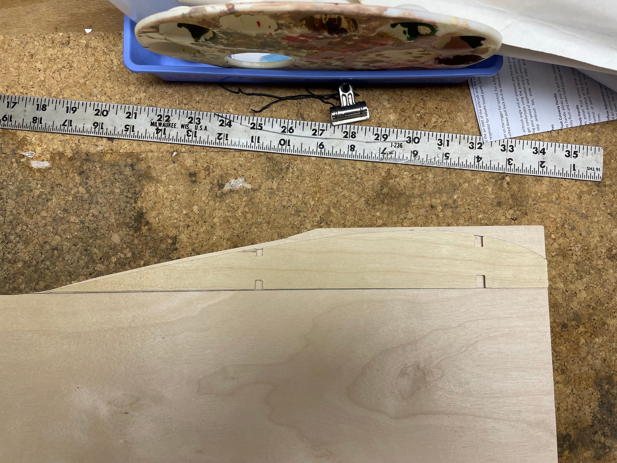
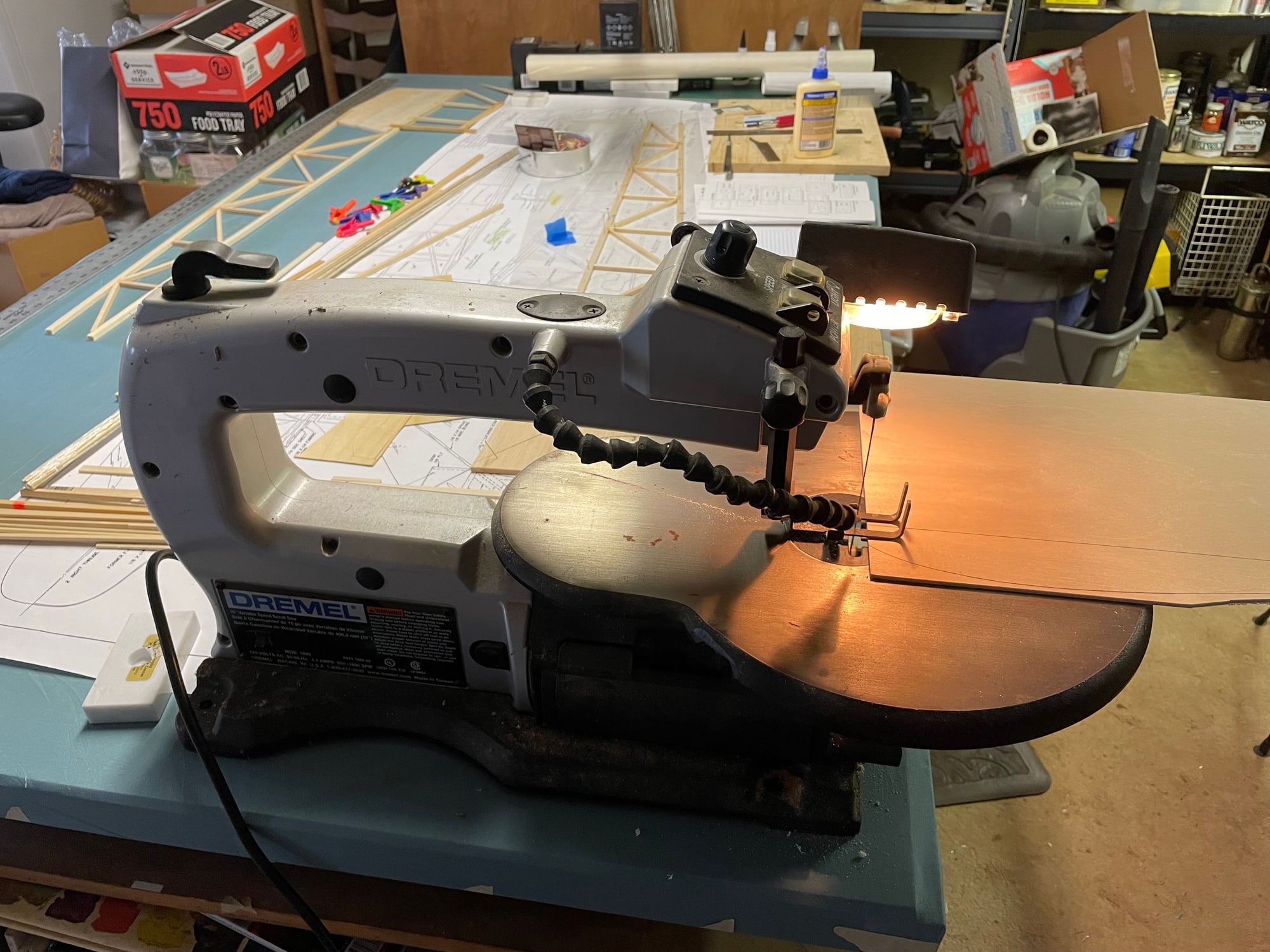
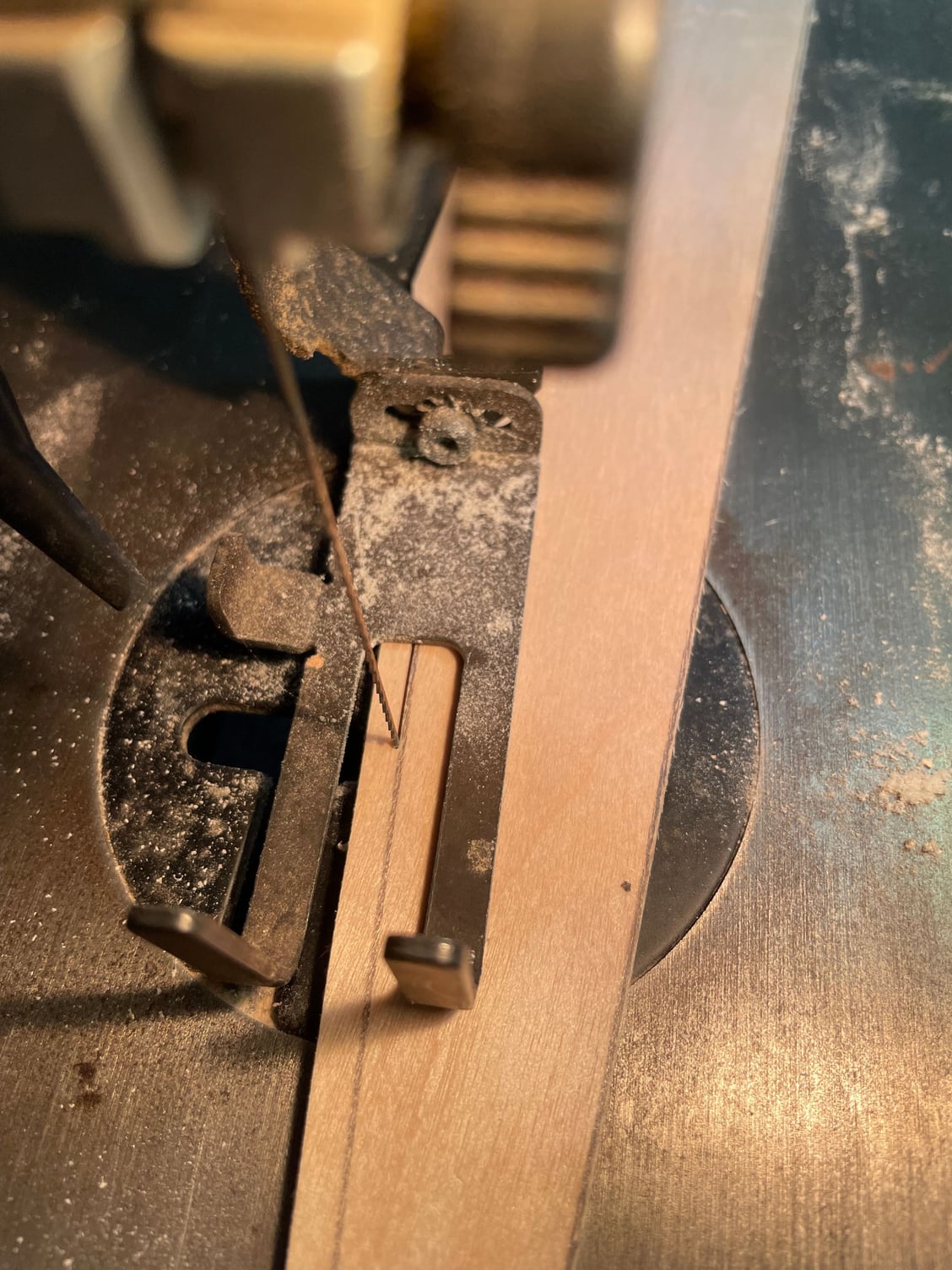
Buying the plywood was real culture shock. The last hobby ply I bought was about $12.50 for a 1'x2'x1/8" piece of aircraft grade. I paid almost $40 for the exact same thing today, wow. Anyway, got it home, used one of the plywood wing root ribs I did get as a pattern, and traced out replacements, then cut them on my scroll saw. I make my cuts just outside the traced line, then sand to fit. Takes longer but is way more precise. When I get them matched to the pattern, I'll laminate them, and then do a final sanding to fit them exactly on the plans. I'll do my measuring, based on some full-scale photos, and drill holes or cut notches as needed. The main spar will go as per the plan, but there is a round tube just behind and below, plus the cross brace tube where the rear spar on the plan is. When this is all added when the fuselage frame gets boxed together, it will hold things together while more scale bracing is added.
09-11-2022, 05:20 PM
#14
I live in Grand Junction CO, if you want trees you have to plant them,the greenhouse added 1 1/2 pounds compared to my j-3. here is a picture of my wing mounting. the wings are similar to the plans where one wing comes off the center section which is built onto the other side, I just built the center section onto the fuselage. The rear alignment plywood was replaced with an all thread rod run thru a brass tube with some washers soldered on the inside of the rib former and a blind nut threaded on the outside so that it can't pull apart, this is placed where a pipe would be on the real one. the front ply could be notched like the real one and decorated but I wanted the full piece for strength. Originally it was glued in but it is now bolted in as I have broken it twice.
I used the stock Sig ply joiner on the front and the all thread rod keeps the rear from rotating. Each wing has 2 6-32 bolts to secure, and the struts are very functional.
the yellow one has about 460 flights, the l-4 has about 50 and is currently waiting for it's 3rd repair. the 1 1/2 lbs makes them fly very different
09-11-2022, 05:29 PM
#15
both cubs are powered with OS GT22 gas engines, they pull fine at 4800' but are not overpowered. J-3 is 16lbs, l-4 is 17.5lbs
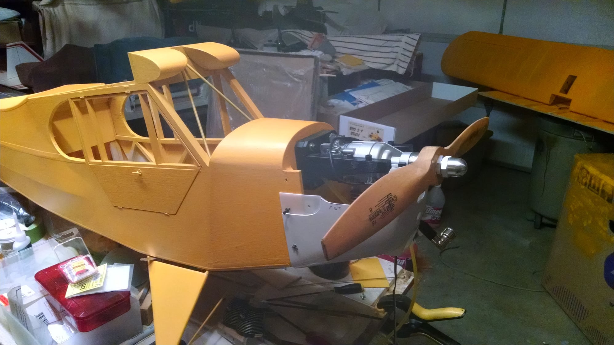
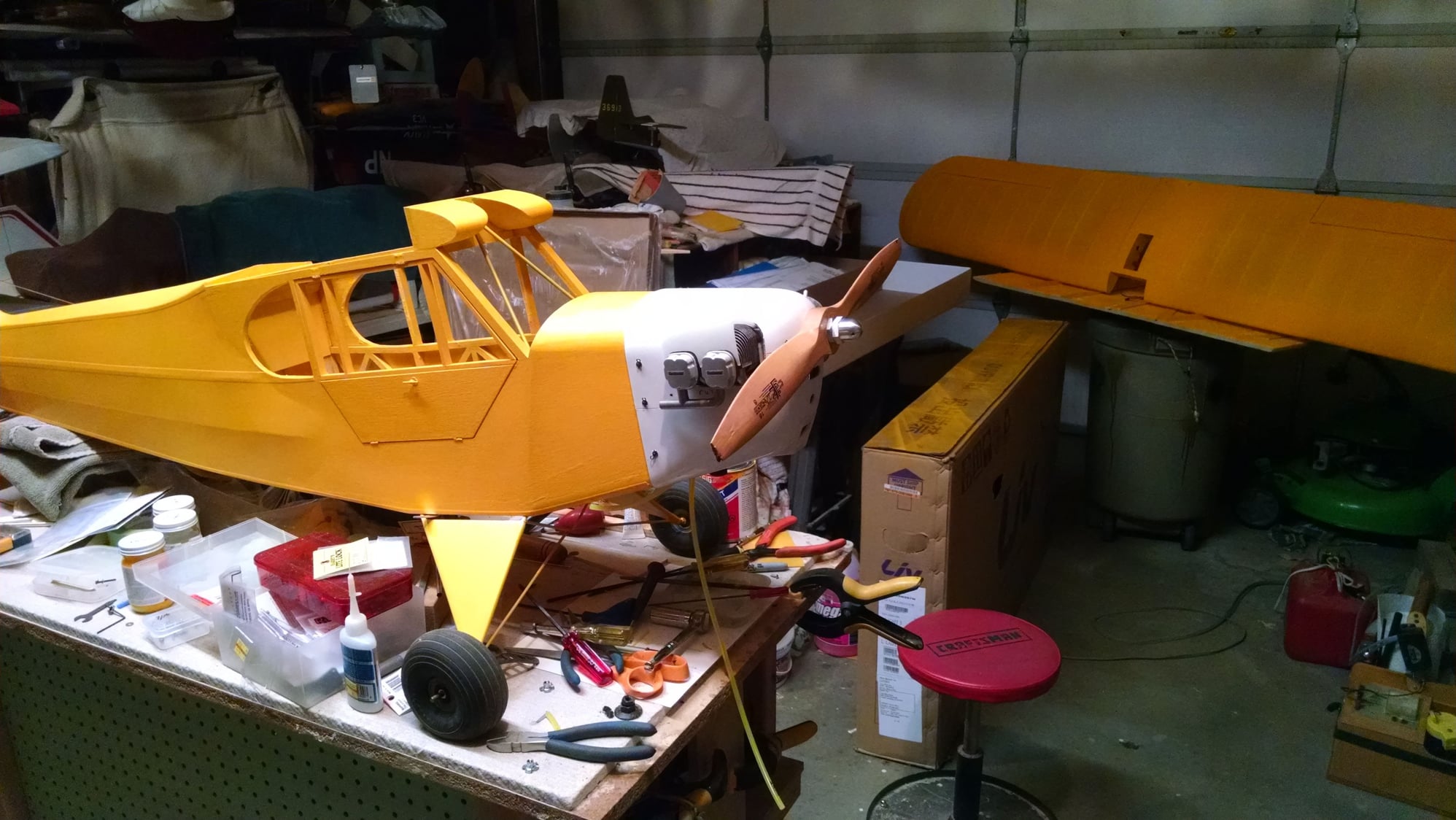
Top Notch Products dummy engine with aluminum eyebrows. eye brows are made to duct air to engine.
Top Notch Products dummy engine with aluminum eyebrows. eye brows are made to duct air to engine.
09-12-2022, 01:45 PM
#16
My Feedback: (14)
Hey Bryan, I grew up in Delta. Joined the Navy right out of high school in '75. Do miss fishing and snowmobiling on Grand Mesa and still have a lot of family in Delta. Wish I could get back more often.
Back to L-4's. The Sig kit is designed a lot different than the BUSA kit, especially the wing center section. Built one Sig 1/4 scale Cub back in the 80's and did not like the wing center and attachment. Think the BUSA kit design is much better, easier to build and easier to make look more scale.
Back to L-4's. The Sig kit is designed a lot different than the BUSA kit, especially the wing center section. Built one Sig 1/4 scale Cub back in the 80's and did not like the wing center and attachment. Think the BUSA kit design is much better, easier to build and easier to make look more scale.
09-12-2022, 07:09 PM
#17
Back to L-4's. The Sig kit is designed a lot different than the BUSA kit, especially the wing center section. Built one Sig 1/4 scale Cub back in the 80's and did not like the wing center and attachment. Think the BUSA kit design is much better, easier to build and easier to make look more scale.
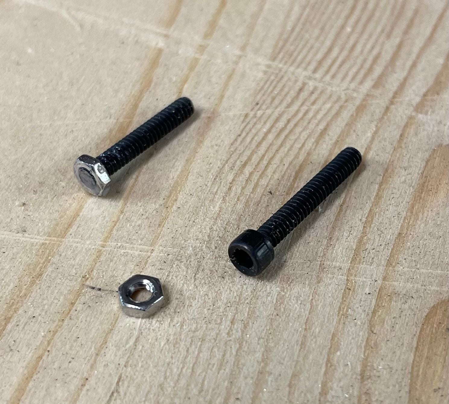
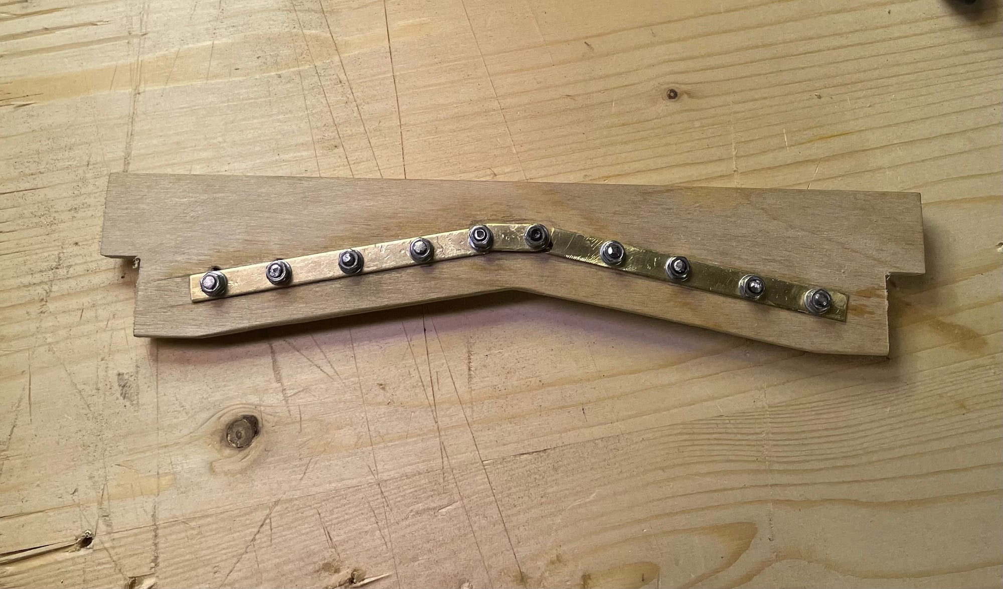
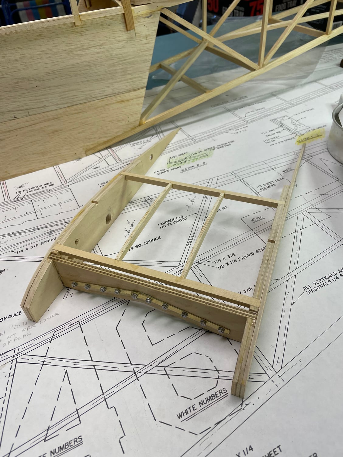
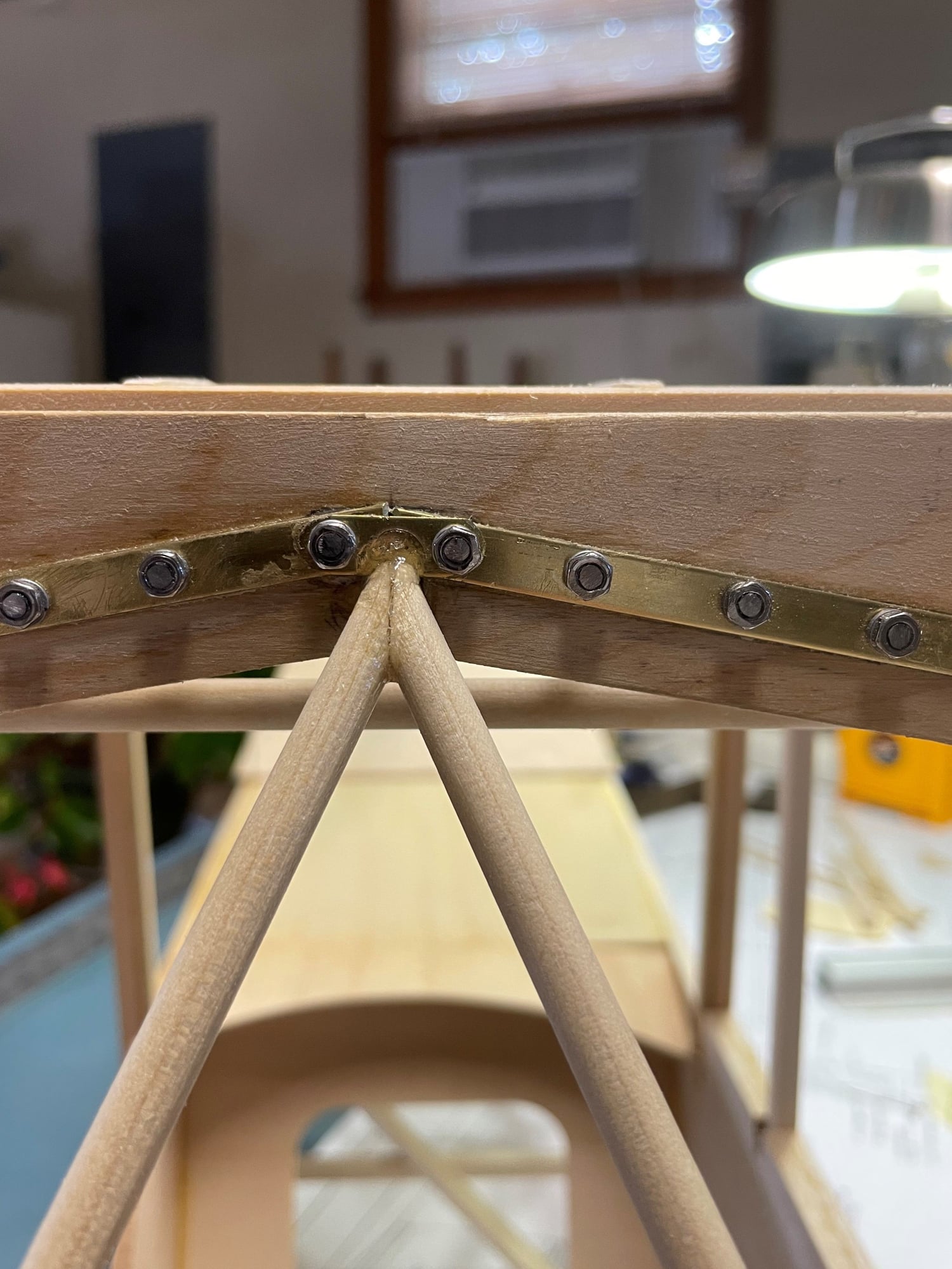
Speaking of center sections, I worked on the center section spar all afternoon, detailing it before attaching it, which is still a little ways off. If you go back a few posts, you'll see the picture i posted of the full size spar attachment. The wing spar stubs joint in the center to the "trapeze", which is firmly anchored to the fuselage framework,. There is a front and rear steel plate that attaches to each spar stub with 4 bolts each side, and a fifth bolt attaches the spar stub to a bracket on the trapeze. The bolts are hex head; I only had socket screws, so I cut the socket head off and threaded a small hex nut and CA'd it in place, to make hex-head bolts in scale. these are 4-40 socket screws, and I used longer than needed, so I could cut them to a proper length. The steel plates are made of brass, glued in place then drilled through the spar and bolted in place. Once fitted in the center section, the trapeze will be built in place, and epoxied to the spar. The epoxy fillets mimic weld joints pretty well. The whole thing gets painted OD green eventually, except the centermost two bolts. I didn't have castle head nuts, so I doubled the small nuts I did have to bulk them up a little. The spar itself is 1/4" ply, the kit shows a 3-piece laminated spar. I will also add a 1/4" dowel just behind and at the bottom of the spar, which is a part of the full scale framework, and will add strength in the spar area on the model.

 09-13-2022, 07:59 PM
#18
Okay, today went sort of slow, had to mow grass. I got the upper door framed, and after using CA to glue it together, I drilled the joints and pinned them, using round toothpicks. I used wood glue to hold them in, working them in and out of the holes to fully distribute the glue. The holes are slightly oversize for this purpose. I used maybe 7/8" of toothpick on each joint, then clipped them flush. I cut the tapered part off before inserting it into the hole.
The corner joints are made "backwards" from the plans; making them the way I did gives a larger glue surface for a stronger joint. Once painted, it's not noticeable anyway.
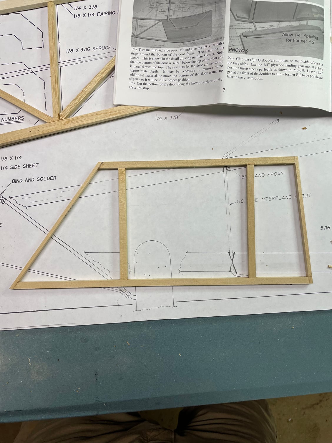
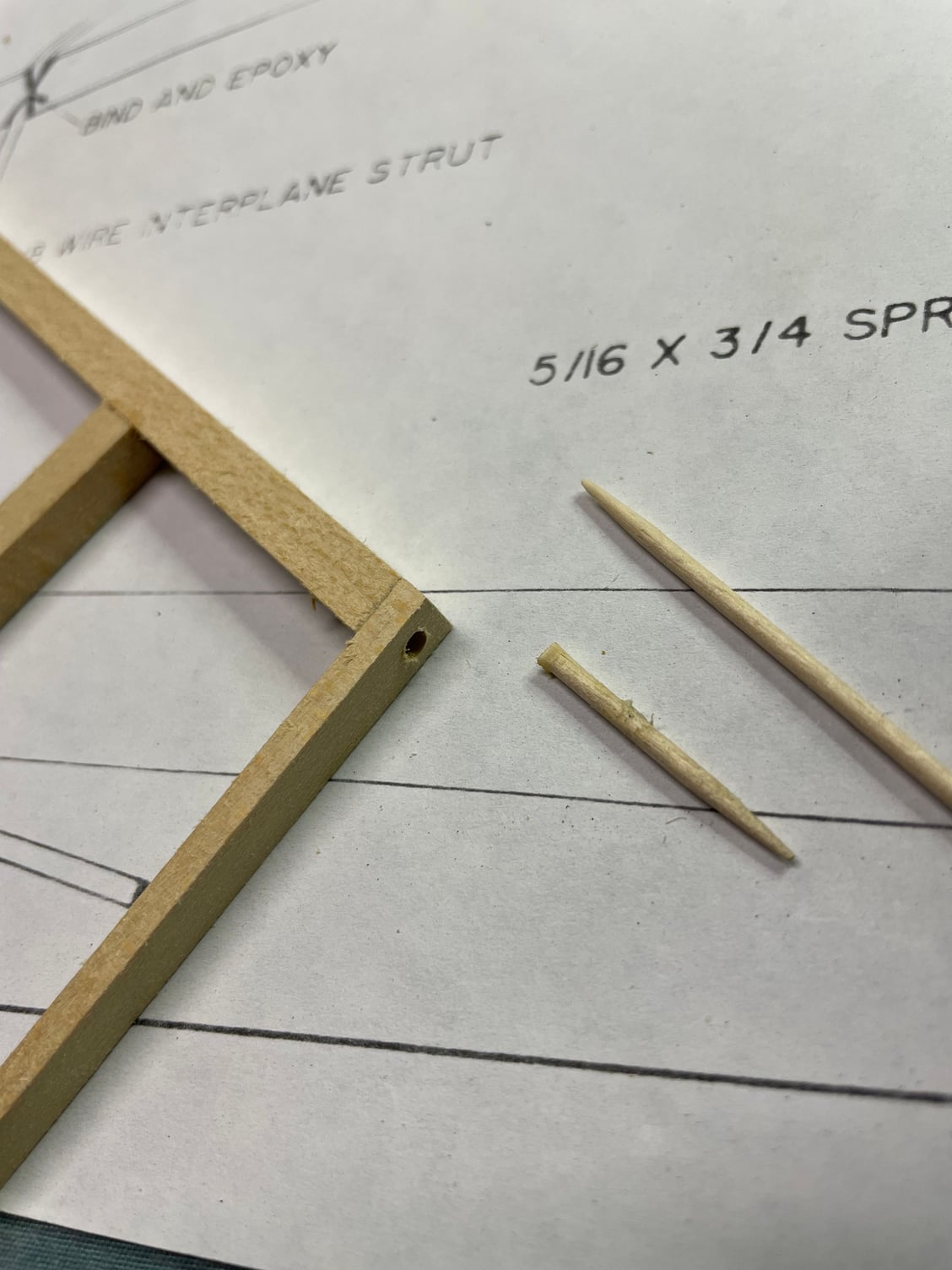
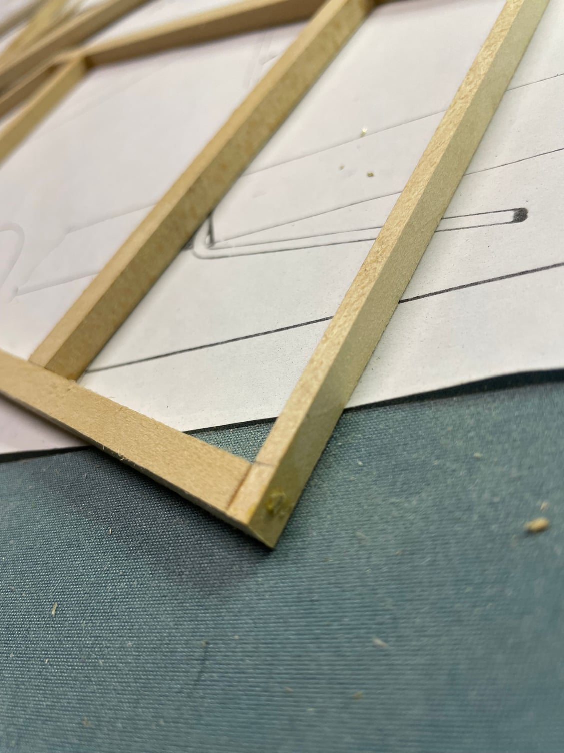
The corner joints are made "backwards" from the plans; making them the way I did gives a larger glue surface for a stronger joint. Once painted, it's not noticeable anyway.
09-15-2022, 05:53 AM
#19
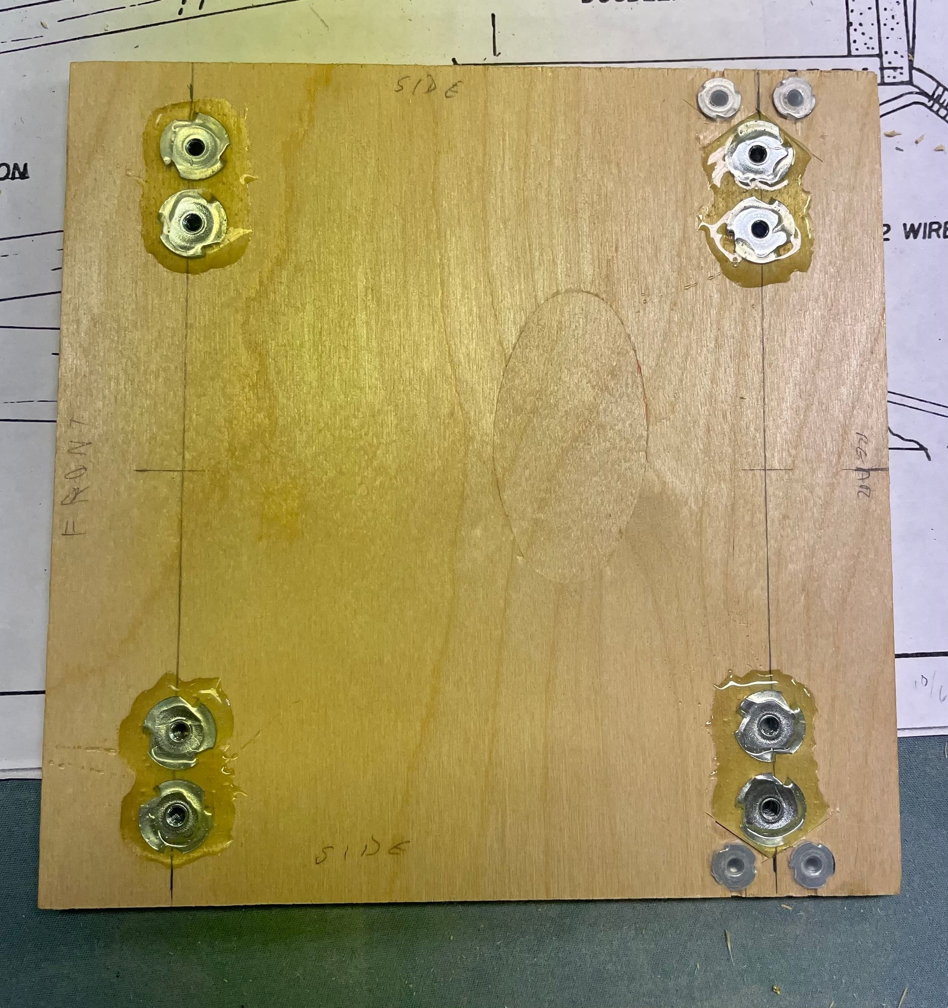
I prepped the bottom plate, or landing gear support yesterday. I'm using Robart scale gear, rather than the soldered wire setup in the kit, so I have to drill holes and install blind nuts, which will be much easier before I glue the bottom to the sides. I am also altering how the wind strurs attach. In the kit, the metal tab on the strut end simply screws to the bottom of the fuselage, which I feel would eventually strip out if disassembled very much. Instead, I'm installing a metal attach point which has to fit under the rear landing gear mounts. That would put them out of level with the front mounts, so I inlet the wood and set the wing strut mount flush, and use two 4-40 screws on each one, which means more blind nuts. I'll shape the bracket later. The landing gear are held with 6-32 screws.

09-17-2022, 07:36 PM
#20
I got the two fuselage sides joined today with the cabin formers and landing gear plate. I had to remake the front former, the one in the kit was warped and pulled the cabin out of true when it was clamped in place, it wouldn't properly align. It is a 1/4" plywood piece, and I didn't have any extra wood that thick, so I cut two pieces 1/8" thick and laminated them with wood glue and put a heavy weight on it until the glue set. It fit perfectly.
09-20-2022, 03:07 AM
#22
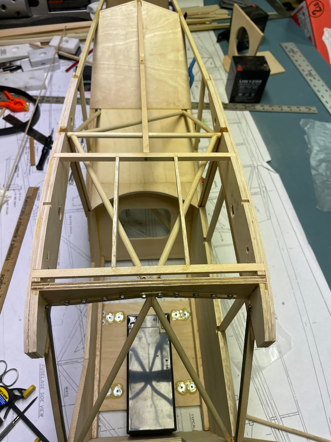
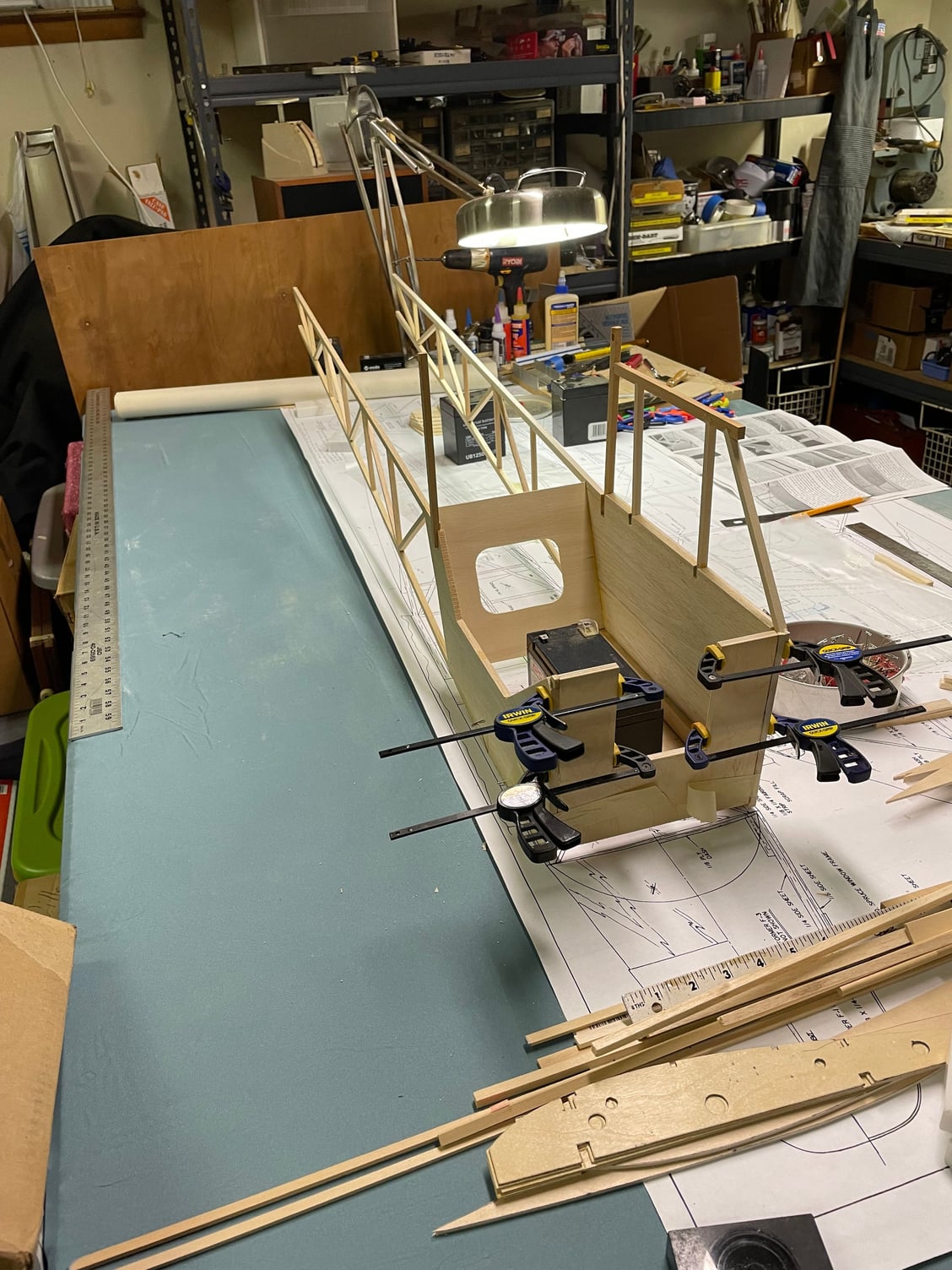
I got the fuselage sides pulled together, with the cross braces and upper fuse formers in place. The forward-most former is omitted when building the L-4, and I have to measure and cut the angled one, which is my next step. I also have to measure and cut the horizontal shelf that goes between the angled former and the rear of the cabin.
I've also determined that I'll use a Saito FG-30 gas 4-stroke for power. I'll probably order it in the next week or so, since I'll have to measure, drill and place blind nuts on the firewall before installing it
I've also determined that I'll use a Saito FG-30 gas 4-stroke for power. I'll probably order it in the next week or so, since I'll have to measure, drill and place blind nuts on the firewall before installing it
Last edited by khodges; 09-20-2022 at 03:11 AM.
The following users liked this post:
RICKSTUBBZ (09-20-2022)
 10-02-2022, 06:40 AM
#24
Not making much progress, no time to dedicate long periods of scratching my head and figuring out where the plans are wrong, and how to correct them. The BUSA plans to convert the J-3 kit to an L-4 are sport-scale at best, but there are some rather significant differences in the fuselage profile between the J-3 and L-4. The L-4 has a more straight spine profile, to accommodate the "greenhouse". The formers in the kit do not reflect this. and are therefore not correct. I have around 100 photos, made from multiple angles, of L-4's profile and structure. made from several examples of the type at various airshows and airports. I have noted that even within the L-4, there are variations between the sub-types (L-4B, L-4J, etc), but the profiles are all similar to each other, and all are different from the J-3. These profile differences all occur between the empennage and the trailing edge of the wing. So, I'm using a technique of "proportioning" to measure pictures where there is a known dimension, to determine the proper size of the same part of the model based on its scale.
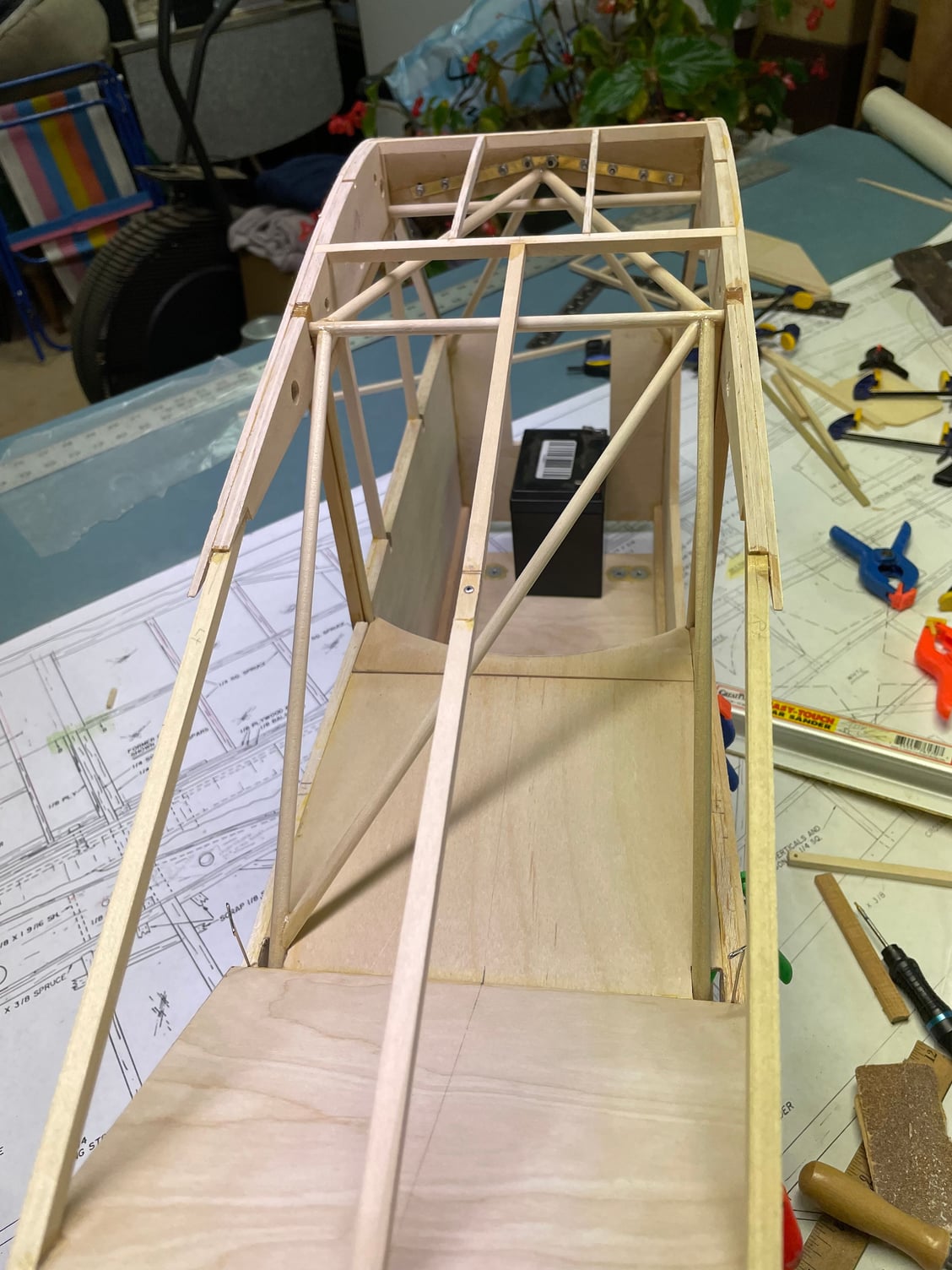
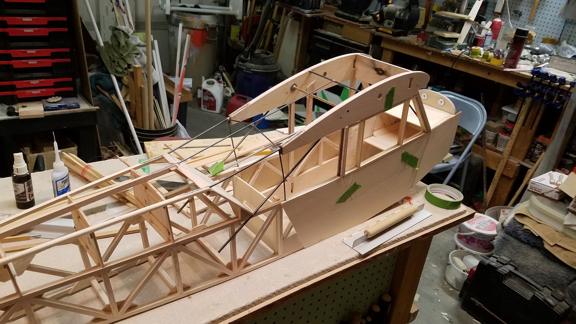
Anyway, still working on that, so I can cut new pieces. Meanwhile, I installed the center section and used some 2-56 size rod to reinforce the "A" pillars, since in scale they are pretty small.

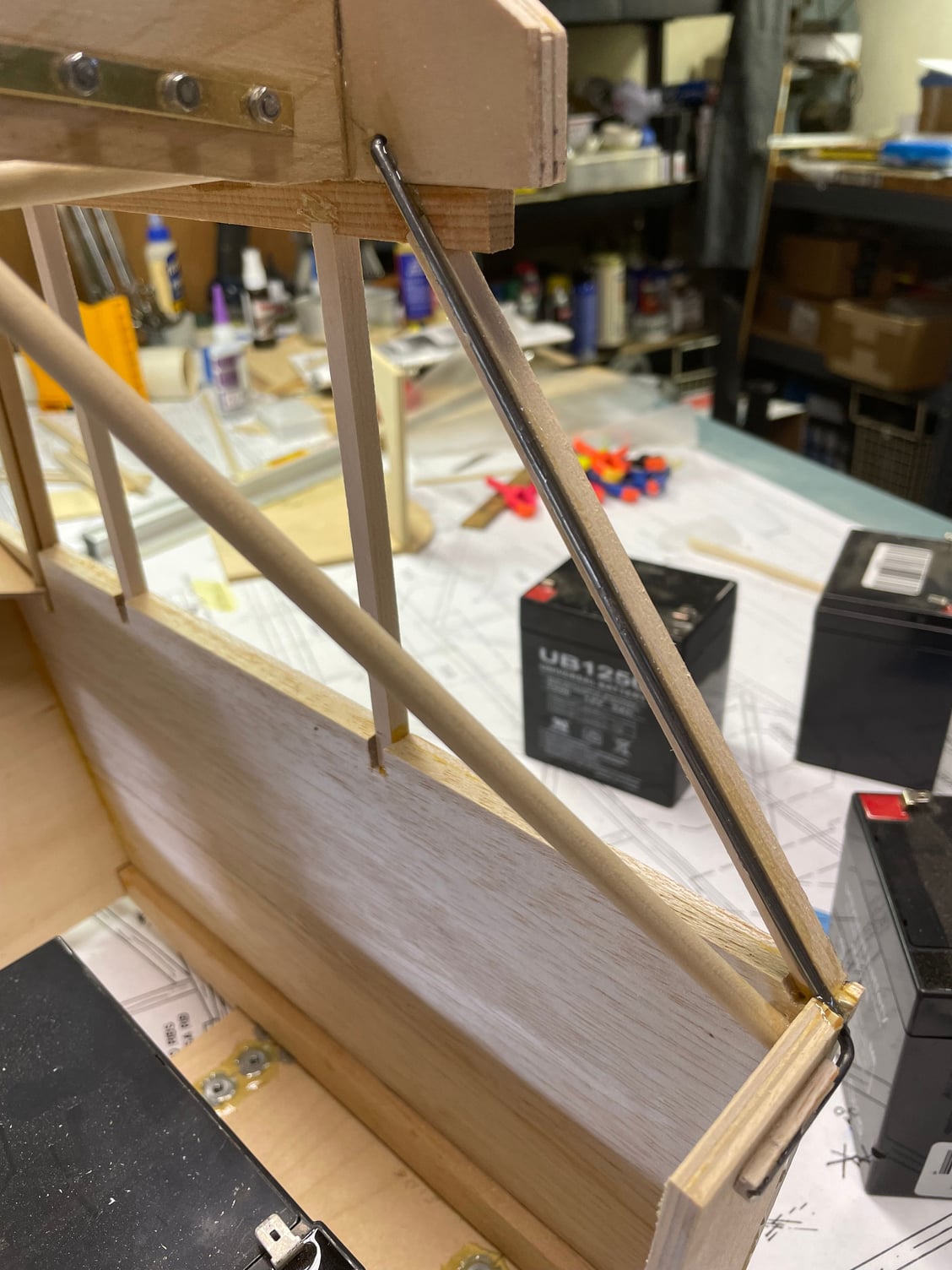
Anyway, still working on that, so I can cut new pieces. Meanwhile, I installed the center section and used some 2-56 size rod to reinforce the "A" pillars, since in scale they are pretty small.
10-08-2022, 08:06 PM
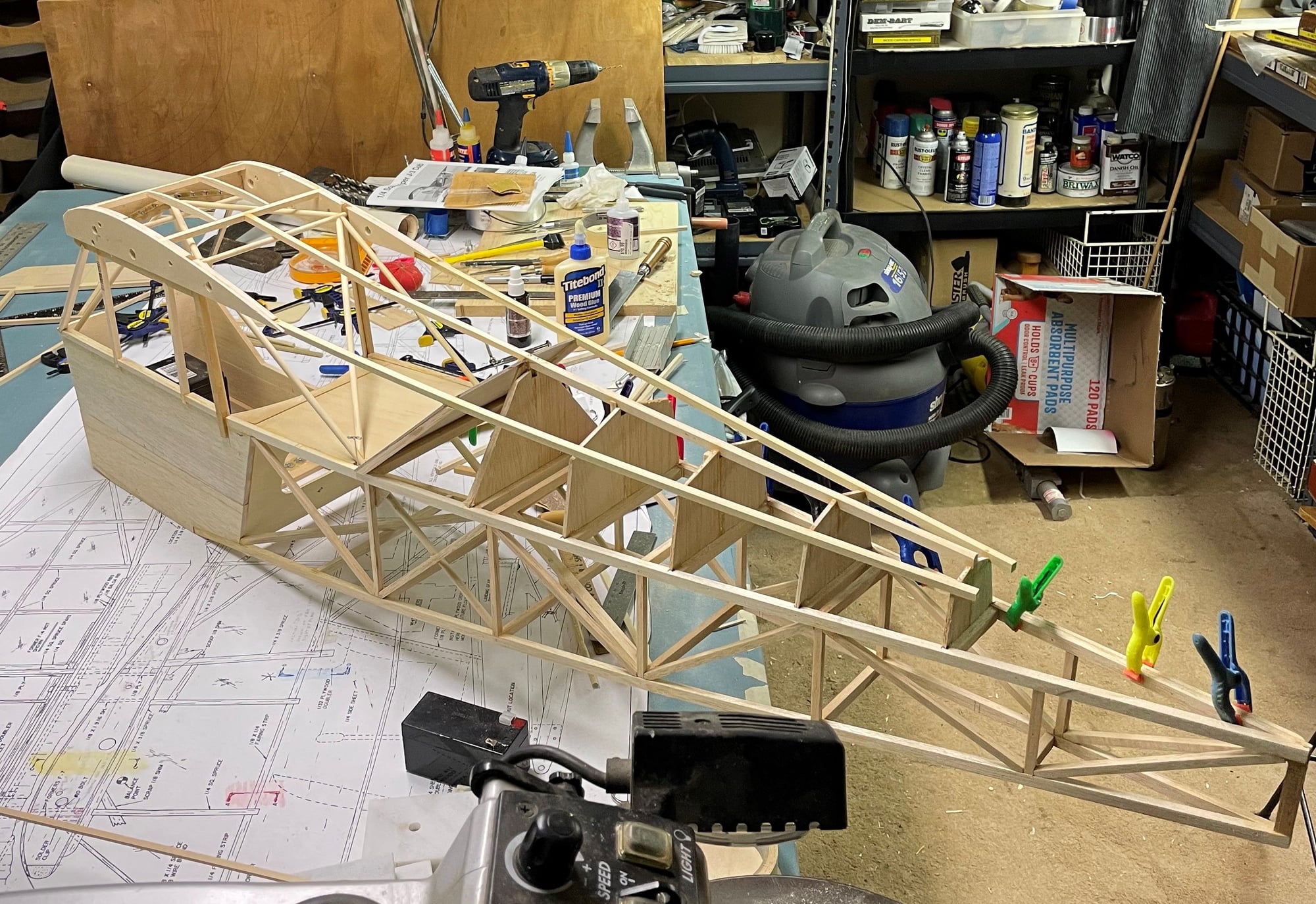
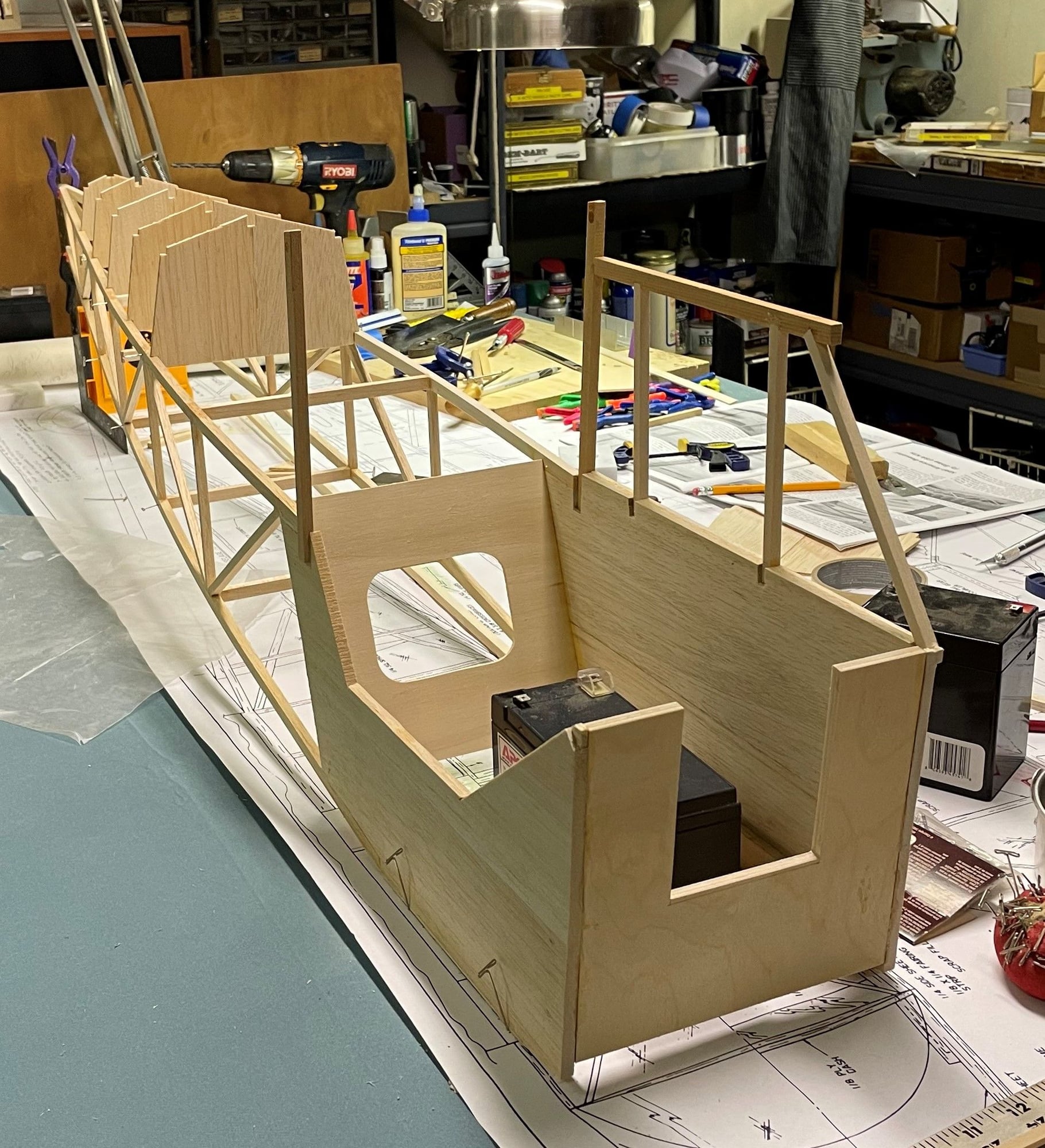
#25
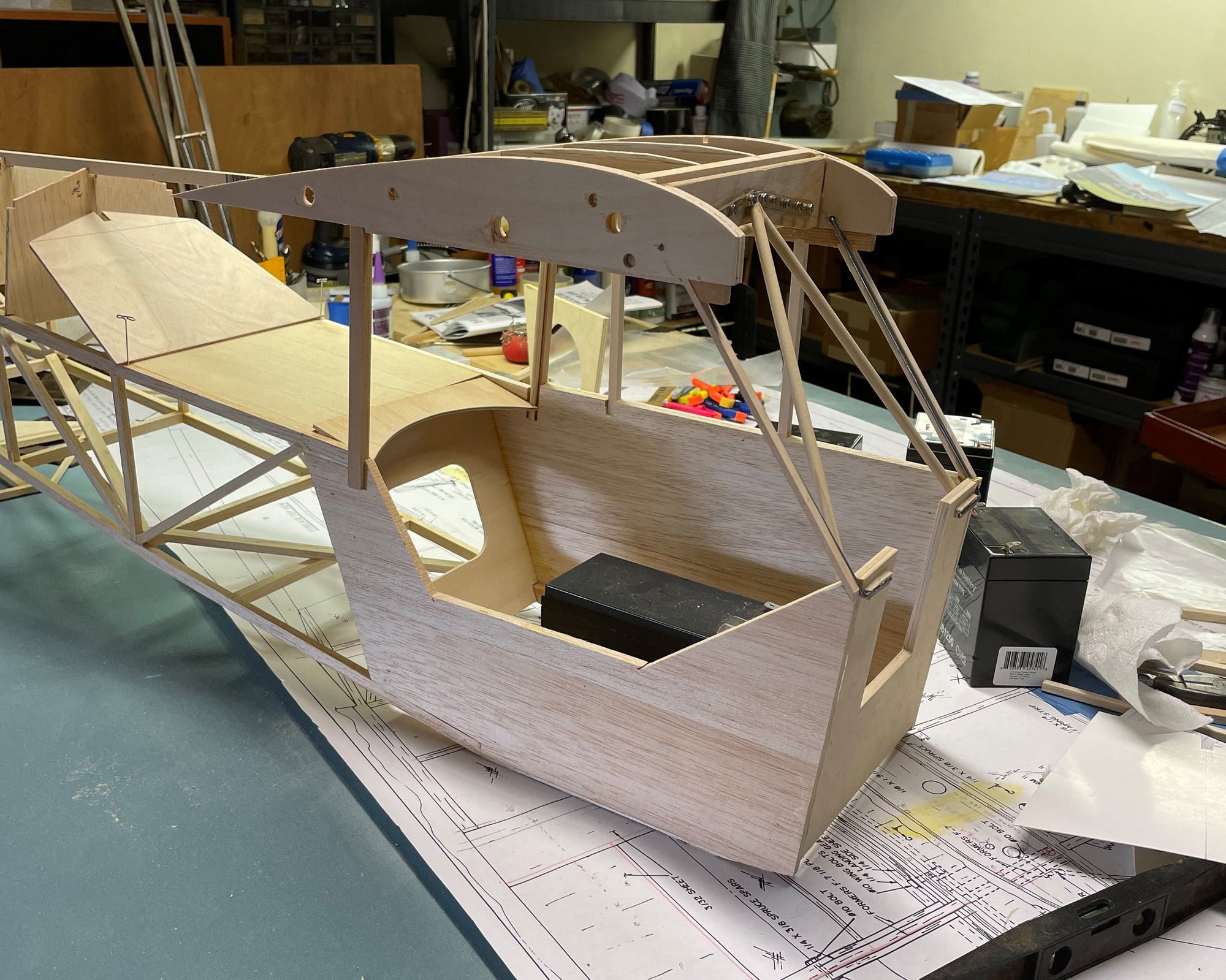
Finally, some significant progress. The engine I decided on is on backorder, and I want to get it before working on the firewall and engine compartment. As I mentioned before, some of the dimensions on the plans are off from the full scale, and the plans don't build the complete greenhouse in the wing center section. I changed several things and after very careful measuring, and mocking up with cardboard and masking tape, I have the basic fuselage and top section framed. There is still some window framing to do on top, but I was at a good place to quit for tonight.