


resistor to reduce 6 volt t0 5 volt
 09-06-2013, 03:36 PM
#1

Thread Starter
I have a 6volt battery on my system and need to reduce the voltage to 5 volt because my lost plane locator cannot work with 6 volts how do I figure what resistor to use on this to reduce voltage to 5 volts. my battery to receiver is Nimah Hi energy battery 2200 mAH 6 volt. Thank you Ken
 09-06-2013, 03:44 PM
#2

I'm pretty sure you want a diode. If you do a search in the gas engine forum you will be able to find out what value diode some guys are using to reduce voltage for ignitions. When you find what you are looking for I would suggest you put it in the + line to your locator only and leave the rest of the system on 6V.
09-06-2013, 04:55 PM
#3
My Feedback: (2)
The problem is that the voltage drop across a resistor is dependent on the current through the resistor: V=IR. So, you would need to know the current that you lost plane transmitter takes in order to determine the value of the resistor. But if the current changes during the operation of your lost plane locator (which it very well may), then the 5 volts won't be 5 volts.
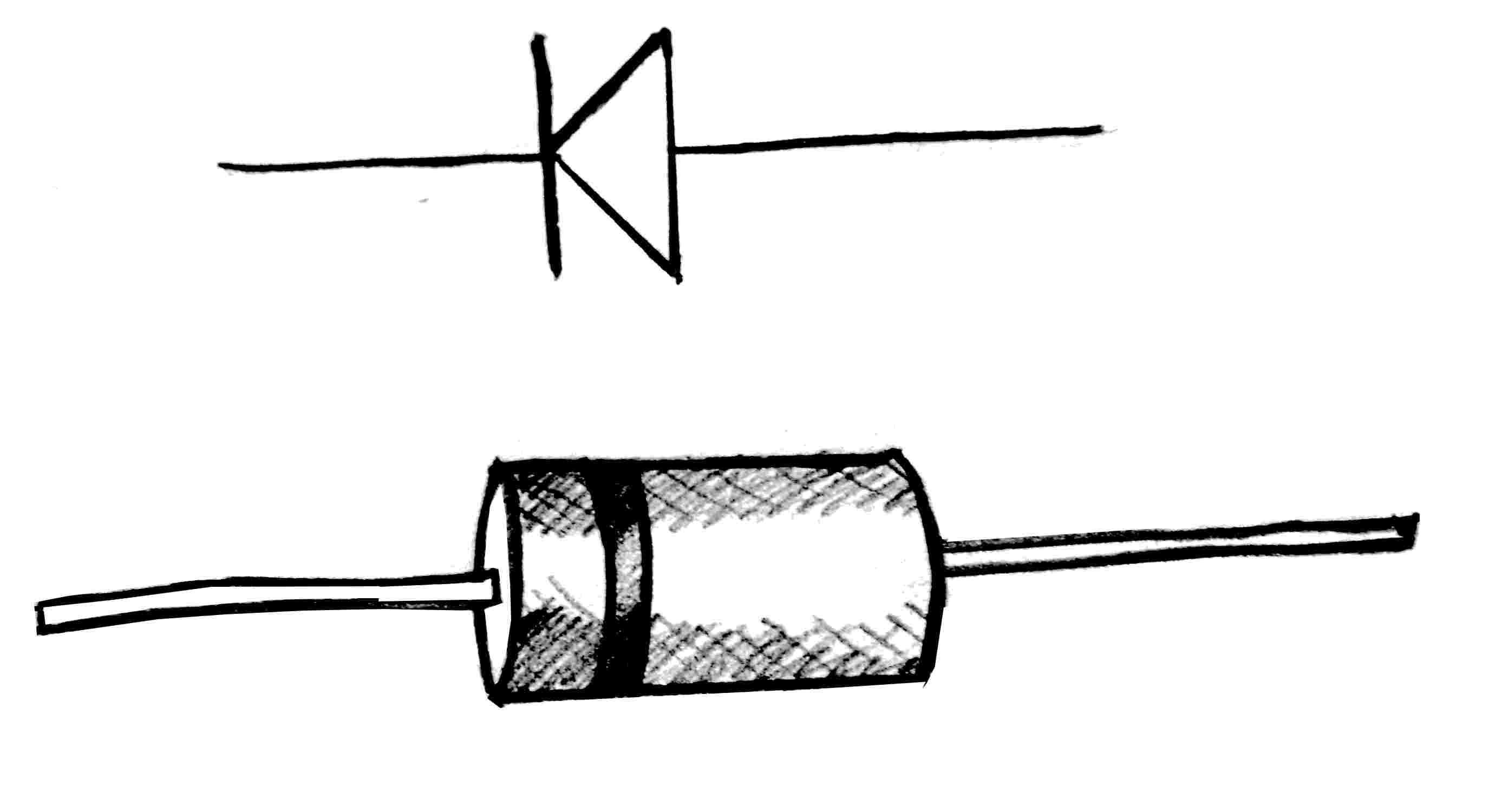
A silicon diode drops about 0.7 volts regardless of the amount of current through it. So one or two diodes (in series) might be what you want. Radio Shack sells them. A common type that should work for you is 1N400X where X can be any digit from 1 to 7. They are only good for 1 amp. If you draw more than 1 amp through one it will likely fail.
A silicon diode drops about 0.7 volts regardless of the amount of current through it. So one or two diodes (in series) might be what you want. Radio Shack sells them. A common type that should work for you is 1N400X where X can be any digit from 1 to 7. They are only good for 1 amp. If you draw more than 1 amp through one it will likely fail.
09-06-2013, 05:19 PM
#4

Get (2) diodes and they can be 1N400X where "X" is a number 1-7. Any of them will work in this application. If you have a Radio Shack around they should have the 1N4004 or 4007. You will want to solder them in series , Each diode will have a flat bar printed on the body toward one of the leads. You want to position the diodes one below the other but so that the black bars are both pointing up. Solder them together in the middle. Then, as mentioned above, insert the diodes into the power lead for the alarm. Snip the red lead between the alarm and the servo plug, Solder in the diodes so the bar is pointing toward the alarm or away from the servo plug. Shrinkwrap this after you are done. Now you can keep 6 volts powering everything else but only around 4,8-5 volts will be going to the alarm.
 09-07-2013, 07:22 AM
#6
Radio Shack also has a bridge rectifier that works very well for making a voltage drop. A BR is a grouping of four diodes in a single component. A how to with pictures http://pages.suddenlink.net/arlyn/rcvotagedrop.html
09-07-2013, 12:17 PM
#8
Thread Starter
Thank you for the info will this work with my Nimah 6v 2200 pack or will it bring the voltage down too much these cells are not voltage of the life ?
thanks again Ken
thanks again Ken
 09-07-2013, 08:20 PM
#11
Moderator
Did you ever think of just buying a lost plane indicator that can work with 6v? It sounds like you're going to a lot of trouble to use a piece of equipment that isn't designed right to begin with.
09-08-2013, 05:10 AM
#12
A diode voltage drop will work for any battery technology. They are normally not used with LiPo because a regulator works well because adequate 'voltage overhead' exist (2-3v difference between input and output). When the difference is less than 2v, the diode scheme works.
One more point about using a bridge to make up the diode voltage drop. Diodes are fairly rugged as long as the rated current capacity isn't exceeded but any electronic component can fail and with diodes failure usually means to open rather than short, which of course would de-power whatever was being powered.
The bridge diode scheme having two parallel legs offers some redundancy should one diode fail.
09-08-2013, 07:00 AM
#13
The way I increase reliability (redundancy) is to use 2 batteries, 2 switches, and 2 wire paths to the Rx. I install diodes in each path to drop the voltage and to guard against the possibility of a short draining both packs. This way any component in the system can fail and I still have power to the Rx. I normally use two 1100 or 1300 mah LiFe batteries which weigh about the same as a comparable size NiMH battery.
09-08-2013, 11:19 AM
#14
My Feedback: (7)
Why do you need to lower the voltage of a LiFe battery? I have been flying all my airplanes with LiFe batteries for years and have never had a problem. I did have a helicopter with a gyro that would not take the LiFe unregulated voltage but that was a specific Futaba gyro and tailrotor servo.
09-08-2013, 11:55 AM
#15
I lower the voltage when I use the LiFe's with my electronic ignition modules...they're designed to use less than 6 volts. My Hitec servos are recommended to use less than 6 volts. My JR retract servo won't work on more than 5 volts so I had to lower the voltage going to it. When I use dual battery packs I use the diodes to protect against shorts. I've also used diodes to reduce voltage going to the tail rotor motor on small heli's.
09-08-2013, 05:31 PM
#16
Moderator
Which Hitec servos aren't supposed to go over 6 volts? You don't mean the spec where they are rated for 4.8 or 6 volt packs do you? Those specs mean the voltage put out by 6 volt NiCd or Nimh packs, which top out at 7.2 volts. That's right there with what a 2 cell LiFe puts out, so there is no possibility of damage there. Yes, servos that are 4.8v only will need the voltage dropped, and there are lots of ignition modules that can't take more than the voltage of a 4.8v pack.
09-08-2013, 06:09 PM
#17
You can read more at these links:
http://www.rcuniverse.com/forum/airt...ml#post9990923
http://www.rcgroups.com/forums/showthread.php?t=1561733
Hitec says that any servo rated for 6v will have degraded life when used at higher voltage.
Here are some quotes:
As mentioned many times, the higher the voltage, the higher the current and faster burnout of all servo with a designated voltage input of 4.8-6.0v., as linked as an aside, JR do not warrant the greater majority of their servo if used above 4.8V.
Few if any models require non HV servo to be run above 5v but in need. would never recommend any be run with LiFe04 or Lipo without a switchmode regulator set to max 6.0v. This especially if using Optima Transceivers etc..
Yes, have heard the argument many times "have done this for one or two seasons, but have also heard just as often of failures, blaming the servo or RX and seen the results more times than users would report to fellow club members. A pity I can not record and post on line some of the many conversations..local aftermarket battery technician/supplier also confirms same discussions..
5 cell NiMH quickly drop to 6.0v whereas LiFE04 do not drop to 6.0.
Only the HS-7955, 7940, 7950, and 7954 servos are rated for 2S lipo.
(A123) Peak voltage is over 7V yes, but A freshly charged 5 Cell NiCd/Mh pack is 6.75v and quickly settles down from there once a load is applied. This is much different than the A123's which start and stay at a much higher voltage.
None of the Hitec servos rated for 6V would require a regulator if using a 5 Cell Ni Cd/Mh. The 225 servos for example pack a lot of punch in a small package but their size means a smaller motor which is more susceptible than a standard size servo with similar torque to overheating if pushed hard. Torque alone should not be the deciding factor when choosing a servo.
Since the 625MG is a standard sized servo it is more capable of handling the A123's but if you're asking it to perform close to it's max then the life would be reduced. Just as any servo... if you need 100in/oz of torque and that's all you have then the servo is operating at 100% where if you use a servo with 200in/oz it's working half as hard so things like motors and amps don't get as hot and the likelihood for failure is considerably lower.
09-09-2013, 12:29 AM
#19
My Feedback: (41)
I see the 4 amp rating on a suggested solution)potential problem using bridge rectifier or diodes!!). I think that's a limitation that attention needs to be paid to. If you start adding any digital servos to the mix or have something in the system draw a few amps it could mean trouble. I HAVE been flying and several club members have been flying with LIFE and JR or Hitec servos and have had no hint of problems. Ignition is another story or other items that could be a problem. I use LIFE 1800 for onboard glow and receiver/servo power combined, at times. Works great. I would be concerned about diodes etc in the receiver/servo area. However to each his own!
Why use a 30C LIFE 1100-1800 pack and then put a 4 amp limited device in the circuit?
Why use a 30C LIFE 1100-1800 pack and then put a 4 amp limited device in the circuit?
09-09-2013, 03:07 AM
#20
I'm not an EE, but it seems to me that the four amp rated bridge rectifier is likely capable of more than four amps when configured as a voltage drop. In normal configuration as an AC supplied bridge, each of the four diodes in the bridge can carry four amps. As a voltage drop, with two parallel legs of two series diodes, the load is shared between two branches and it therefore seems to me that the capacity theoretically doubles albeit less than so given the probable need to dissipate more heat.
I've the ability to test my theory and will do so sometime using a six amp load.
I've the ability to test my theory and will do so sometime using a six amp load.
09-09-2013, 04:31 AM
#21
I'm not saying that what you're doing won't work (even though Hitec does recommend against it)...just that having full dual redundancy seems to be a better solution.
 09-09-2013, 06:56 PM
#23
Senior Member
My Feedback: (1)

Join Date: May 2009
Location: Miami,
FL
Posts: 377
Likes: 0
Received 0 Likes
on
0 Posts
I'm glad there are more interested about electrical system of their RC using other option... I remember when I was in young I used diode other than rectifier to protect equipment from reverse polarity. Now I'm using it also on my F-18 hornet just like most of us did on their plane. I'm using mine for my backup battery to prevent from flowing the current back to the battery and preventing also to operate when voltage is within 6V from the output of main battery with regulator. I used 6A 50V diode at + feeder wire from the backup battery.
09-09-2013, 07:19 PM
#24
Senior Member
My Feedback: (1)
Join Date: May 2009
Location: Miami,
FL
Posts: 377
Likes: 0
Received 0 Likes
on
0 Posts
To answer OP, you can use resistor as voltage divider to gives you 5V output but it must be lower resistance to increase voltage regulation or you might need to put zener and capacitor for constant output depending on your power requirements. I discourage to use it since we have lots of available ready to use items in the market,and aside from that power dissipation is higher...
09-09-2013, 07:38 PM
#25
Senior Member
My Feedback: (1)
Join Date: May 2009
Location: Miami,
FL
Posts: 377
Likes: 0
Received 0 Likes
on
0 Posts
Using bridge type rectifier diode is similar to using single diode on one terminal aside from both terminals were provided with diode each causing to cut 2x0.7v from the terminal voltage. It is used to convert AC to full wave rectification, in other words you can interchange your battery polarity with no problem. Just a single diode is enough to do the job for each battery provided it's stalled properly and specified correctly. BTW, it's not used to replace the function of regulators because they are different although both can be used in power supply.
Very well said radfordc...!
Very well said radfordc...!
Last edited by rctech2k7; 09-09-2013 at 07:58 PM.