


In-Line Twin projects
 10-03-2014, 03:55 PM
#201
Senior Member
Thread Starter

Join Date: Aug 2013
Posts: 444
Likes: 0
Received 0 Likes
on
0 Posts
Fuel filters arrived so nearly ready for some runs, just got to bolt things down fully.
For now I've temporarily mounted one temperature and one tacho sensor. The rig will only take one tacho reading so the tiny servo you can see in the pic on the bench will be operating a switch to choose front or rear engine RPM readouts. RPM telemetry is there for tuning, not balancing, as the two different engines will only coincide by accident, they are bound to run at different RPM's throughout normal use. Frankly listening is better for balancing a true engine pair, but for this purpose I'll be able to see the engines' performance acting together under way.
The two servos have their control rods, and the radio set so both throttles are operated on the one stick, with a rotary knob on the transmitter assigned to adjust the engine balance. The servos are each set to achieve a linear action on the throttle for now, I'll adjust the curves as the engines run in more, and will again once the boat is under way. Two side levers on the transmitter control independent engine shut downs.
I'm looking forward to seeing what can be done with the pumps. The tanks are mounted on a movable arm so I can position them easily at different heights. I've gone for regular aircraft tanks but with a fixed pickup pipe, no clunk. Unable to find a decent shaped and sized car tank I'm resigned to pumping fuel to fill in the more usual fussy way, plus these tanks are a perfect size.
At last, after this is proven one way or another, I'll know what can be done to finalise the boat's design. The ultimate aim would be to have the tanks as low as the test model, but with better throttle responses. If I can get lower even better.
 10-04-2014, 10:44 AM
#202
Senior Member

Join Date: Dec 2013
Posts: 432
Likes: 0
Received 0 Likes
on
0 Posts
Those tanks look to be quite a distance there J, is that the proposed distance only in line with the engines in the end assembly? With the fixed pickup pipe that should eliminate quite a bit of agitation in the fuel.
10-04-2014, 01:58 PM
#203
Senior Member
Thread Starter
Join Date: Aug 2013
Posts: 444
Likes: 0
Received 0 Likes
on
0 Posts
The tanks in the pic are at carb height. so the close one is right next to the pump, it does look like they are bigger tanks but lower in that image.
Fuel foaming is nowhere on the cards here. even the test boat had zero foaming, so this better mount certainly won't have that as a problem. In the test I ran today the tanks are further than they will be, and much shorter fuel line runs than I'm using.
I put a couple of tanks through both engines in a regular fuel setup today, in a running in stylee. They are pretty much there now but the 32 is certainly further behind. I got them to a place where they were throttling reliably, with maybe some tweaking on the 32's idle setting needed.
Switching to pumped operation to the Perry manual way had the 40 running OK, but the 32 would not settle due to gross overfuelling. To achieve the first stage of the recommended setup routine the needle valve was nearly closed with the pump still delivering too much on as low a setting as I dare. The method they give is to run the engine to full throttle on a stated rich setting on the needle, adjust the pump to achieve a rich setting if it's not there, then back in the needle to max RPM. The next op is to adjust the idle setting. So at the this point I've not got to the second stage as I couldn't get max RPM without the needle being nearly shut. I've no idea how far the adjusting screw on the pump will move out, suffice to say that it feels too loose beyond where I was.
So I introduced the T off's to relieve some of that pressure, but simply routed it back to the free vented tank, no header. This improved things significantly, I am now able to rev out the 32 and get some degree of a rev range, there's a bit in the midrange it's still not happy with, but OK at idle and max. I'm now in a position to try the idle setting, something for another time as I'd made quite enough noise in the neighbourhood for the day.
All through this the 40 behaved impeccably, with each setup change it dialed in easily and gave a full rev range throughout, lovely engine. The 32 is on probation as it's an angry little sod in need of some discipline
The delivery from these pumps is surprising, the return lines clearly show a solid stream of fuel entering the tank, so the remaining bit is tempering that flow. What I do have now is the confidence that I can use the header tank with freefall overflow idea from way back, as there's more than enough fuel flow to allow that.
Btw the thrust from the correct props for the first time was very encouraging, no measurements, but a possibly greater cumulative thrust than I noted on the test boat
Last edited by Jeremy_H; 10-04-2014 at 03:26 PM.
10-04-2014, 07:41 PM
#204
Senior Member
Join Date: Dec 2013
Posts: 432
Likes: 0
Received 0 Likes
on
0 Posts
One curious thought comes to mind, has the 32 been run without the front engine running during your testing? Just wondering if the airflow from the front engine may be impacting the performance of the 32 in a negative manner at different throttle settings ") If the 32 is set up independently with a stand alone tank without a pump and then introduce the 40 to evaluate the difference in performance of the 32 it may provide a clue as to why it's acting up. You've likely already gone through all this, just a thought
If the 32 is set up independently with a stand alone tank without a pump and then introduce the 40 to evaluate the difference in performance of the 32 it may provide a clue as to why it's acting up. You've likely already gone through all this, just a thought
If the 32 is set up independently with a stand alone tank without a pump and then introduce the 40 to evaluate the difference in performance of the 32 it may provide a clue as to why it's acting up. You've likely already gone through all this, just a thought
10-05-2014, 06:09 AM
#205
Senior Member
Thread Starter
Join Date: Aug 2013
Posts: 444
Likes: 0
Received 0 Likes
on
0 Posts
The 32 is the front engine, it's the one that is in effect a normal installation, and not impacted by the second engine.
However, it's academic now as I sussed it.
After I posted here last night a dug around a bit deeper on the net regarding the bypass system. What I hadn't come across before was the position the T off should be in, and the missing element proved to be that. It seems the best place to leak off the surplus pressure is as close to the needle valve as possible, with the very best position being on the carb itself. Buried in Perry's site a little was a note on bypass systems, and there it's reported as needing to be 1" from the NV. On these engines I went for rear mounted NV's for safety, but that's left me with a handicap in the length of tubing between the needle and the carb which moves a Tee off position over two inches from the carb. Add the length of tubing I had and it was way off the mark. Reading around this need for the bypass to be close seems universal, so whilst the 40 seems quite happy like it is as soon as I moved the tee off to immediately before the NV on the errant 32 and re-ran the setup procedure it all came good. I changed the 40 to this close T arrangement too but it didn't seem to make any difference to the engine that was working already.
I now have what I need, and with the tests carried out with tanks at deck level I can revert back to the original design of cockpit without any silly pseudo air intakes. It just all got a lot simpler.
By the time I'd finished today I had engines behaving as if they were in a regular installation. The only remaining issue on the 32 is the thing that pretty much all RC engines do, over cool if on idle for a long time, needing to be coaxed back into throttling out. The rear 40 doesn't do this, it keeps heat in the head much better being reversed I guess, but this is a minor problem which can be cured with on board glow power. I've been looking at an auto system which rolls off according to RPM and I might go that way for the hell of it, but it's costly so I may just have a couple of micro servos on switches in the radio box 'Y'd into the throttle servos, to give an on/off for low revs for little cost. It would be nice to be able to launch without running a high idle when carrying this thing to the lakeside.
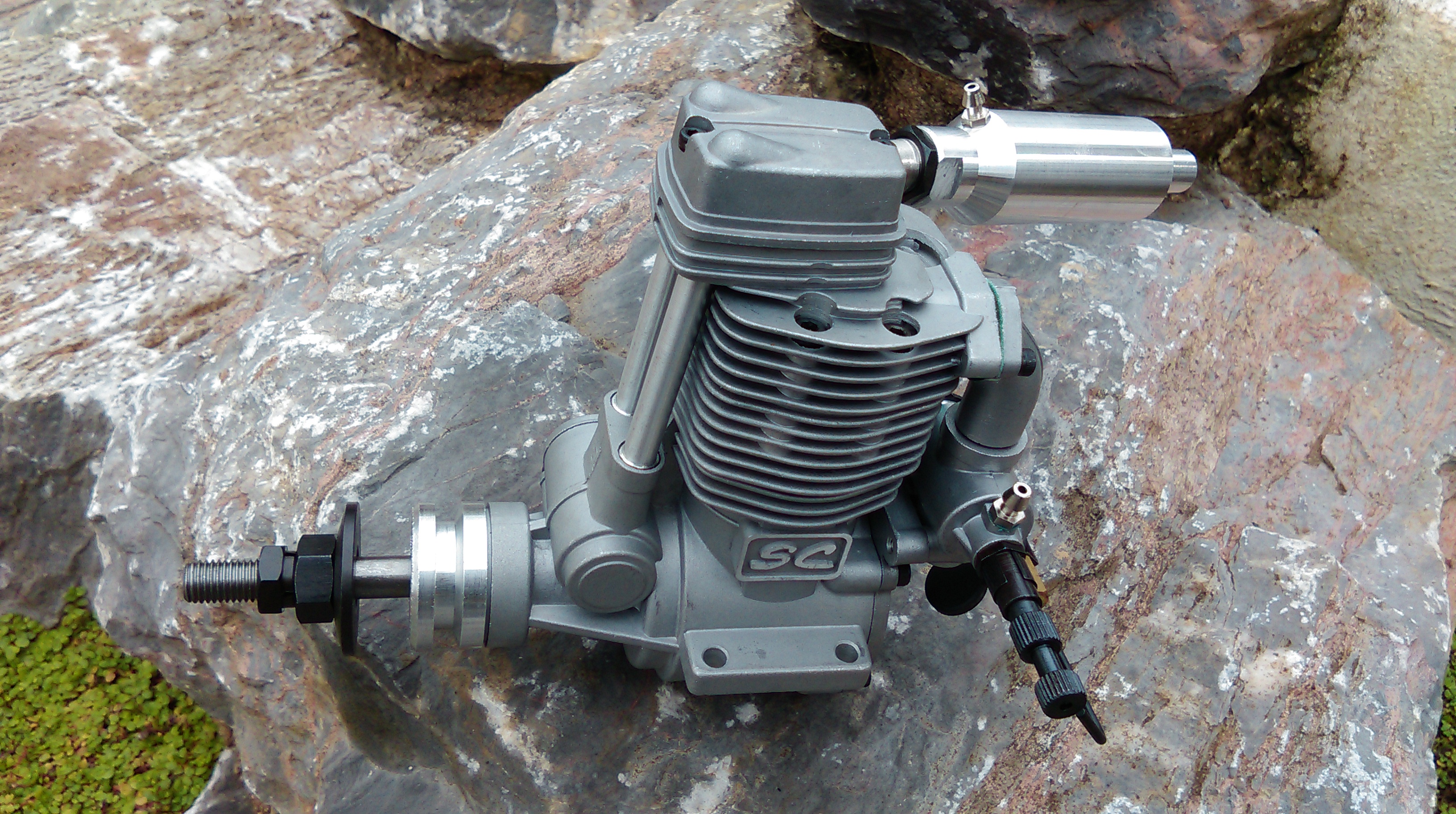
https://www.youtube.com/watch?v=4a-mfEhPY3k&feature=youtu.be And now a complete diversion, for an Airboat to come. I've always wanted a Four Stroke Nitro motor, but the cost has put me off, so having such success with the budget SC motors I have now ('Super Crap' as they are called) I've bought their version of a 91. I've no idea what I'm going to put it in
However, it's academic now as I sussed it.
After I posted here last night a dug around a bit deeper on the net regarding the bypass system. What I hadn't come across before was the position the T off should be in, and the missing element proved to be that. It seems the best place to leak off the surplus pressure is as close to the needle valve as possible, with the very best position being on the carb itself. Buried in Perry's site a little was a note on bypass systems, and there it's reported as needing to be 1" from the NV. On these engines I went for rear mounted NV's for safety, but that's left me with a handicap in the length of tubing between the needle and the carb which moves a Tee off position over two inches from the carb. Add the length of tubing I had and it was way off the mark. Reading around this need for the bypass to be close seems universal, so whilst the 40 seems quite happy like it is as soon as I moved the tee off to immediately before the NV on the errant 32 and re-ran the setup procedure it all came good. I changed the 40 to this close T arrangement too but it didn't seem to make any difference to the engine that was working already
.I now have what I need, and with the tests carried out with tanks at deck level I can revert back to the original design of cockpit without any silly pseudo air intakes. It just all got a lot simpler.
By the time I'd finished today I had engines behaving as if they were in a regular installation. The only remaining issue on the 32 is the thing that pretty much all RC engines do, over cool if on idle for a long time, needing to be coaxed back into throttling out. The rear 40 doesn't do this, it keeps heat in the head much better being reversed I guess, but this is a minor problem which can be cured with on board glow power. I've been looking at an auto system which rolls off according to RPM and I might go that way for the hell of it, but it's costly so I may just have a couple of micro servos on switches in the radio box 'Y'd into the throttle servos, to give an on/off for low revs for little cost. It would be nice to be able to launch without running a high idle when carrying this thing to the lakeside
.https://www.youtube.com/watch?v=4a-mfEhPY3k&feature=youtu.be And now a complete diversion, for an Airboat to come. I've always wanted a Four Stroke Nitro motor, but the cost has put me off, so having such success with the budget SC motors I have now ('Super Crap' as they are called) I've bought their version of a 91. I've no idea what I'm going to put it in
10-05-2014, 12:27 PM
#206
Member
Join Date: Aug 2013
Posts: 65
Likes: 0
Received 0 Likes
on
0 Posts
Hello.
Interesting and perfect work Jeremy. I'm interesting in these pumps. In which engines they can be used. I thought about capacity of the engines. How much that pump cost and where can I buy it ? ? ?
I dream about that engine for Airboat, but in Poland it cost a bit.
http://www.topmodel.fr/en/product-de...to-fg-57ts-gas
We're waiting on next updates and finished Airboat.
10-05-2014, 01:54 PM
#207
Senior Member
Thread Starter
Join Date: Aug 2013
Posts: 444
Likes: 0
Received 0 Likes
on
0 Posts
Hehe, that Saito engine is lovely  . It would need to be a very large RC airboat, it needs the same size prop as this:
https://www.youtube.com/watch?v=XhU2rk8pH1I&list=UUw8b4mq7g44FwvGq97q6aKw
The Perry VP30 pumps I have are for two strokes, they say it can be used on engines between .15 cu in and 3.00 cu in. For petrol there's there's the VP40SG, for four stroke nitro the VP20, and for four stroke petrol the VP22SG : http://www.perrypumps.com/prod02.htm
. It would need to be a very large RC airboat, it needs the same size prop as this:https://www.youtube.com/watch?v=XhU2rk8pH1I&list=UUw8b4mq7g44FwvGq97q6aKw
The Perry VP30 pumps I have are for two strokes, they say it can be used on engines between .15 cu in and 3.00 cu in. For petrol there's there's the VP40SG, for four stroke nitro the VP20, and for four stroke petrol the VP22SG : http://www.perrypumps.com/prod02.htm
10-05-2014, 02:56 PM
#208
Senior Member
Join Date: Dec 2013
Posts: 432
Likes: 0
Received 0 Likes
on
0 Posts
Pardon my confusion  At least you've got it sorted, well done! Let me know what'll be a good candidate for the 4 stroke, I've got an OS and a Thunder Tiger both 4 strokes in the box looking for a home.
At least you've got it sorted, well done! Let me know what'll be a good candidate for the 4 stroke, I've got an OS and a Thunder Tiger both 4 strokes in the box looking for a home.
10-05-2014, 03:21 PM
#209
Senior Member
Thread Starter
Join Date: Aug 2013
Posts: 444
Likes: 0
Received 0 Likes
on
0 Posts
Cheers arc. OS four strokes are really nice from what I understand. So far I've only seen thumpers on boogie board boats, but I see mine heading in the direction of a CAT, maybe something like this:
https://www.youtube.com/watch?v=2l7h4dVD35Q Or this multistep design:
https://www.youtube.com/watch?v=VLBohFg8FxY Or how about this beasty
https://www.youtube.com/watch?v=uq29qQZm2IM
anyway, I'm diverting again, stick to it Jerry lol!
https://www.youtube.com/watch?v=2l7h4dVD35Q Or this multistep design:
https://www.youtube.com/watch?v=VLBohFg8FxY Or how about this beasty
https://www.youtube.com/watch?v=uq29qQZm2IM
anyway, I'm diverting again, stick to it Jerry lol!
10-05-2014, 03:51 PM
#210
Senior Member
Thread Starter
Join Date: Aug 2013
Posts: 444
Likes: 0
Received 0 Likes
on
0 Posts
10-07-2014, 02:48 PM
#213
Senior Member
Thread Starter
Join Date: Aug 2013
Posts: 444
Likes: 0
Received 0 Likes
on
0 Posts
That prop on the Russian boat is a curiosity, two blades rotating together. I wonder what that's about.
Calculated and tested Marek? I guess it depends on what you expect from it, power vs weight is the old issue of two and four strokes, with the different torque curves they each have. Fun, quieter and a great sound is enough to appeal to me, so a boat with character over performance would suit me well. If it has both then great
Some more progress on the twins today, started making parts for the pylon anchor points which need to go into hull next. And just to add to the oddities on this one a combined brake/rudder idea. More on that once I've proven it's viable and I've talked myself into it
.
10-07-2014, 03:59 PM
#214
Senior Member
Join Date: Dec 2013
Posts: 432
Likes: 0
Received 0 Likes
on
0 Posts
I kind of suspect the double prop on the Russian boat acts in a similar manner to a standard 4 blade only I would suspect the second prop to pickup disturbed air unless it's appropriately placed for timing of the air stream
You are aware most people experiment with one or possibly two items at one given time, I have to tip the hat and give you kudos for everything your putting into this boat
You are aware most people experiment with one or possibly two items at one given time, I have to tip the hat and give you kudos for everything your putting into this boat
10-08-2014, 11:58 AM
#215
Senior Member
Thread Starter
Join Date: Aug 2013
Posts: 444
Likes: 0
Received 0 Likes
on
0 Posts
I'd like to sound you out about my rudder idea. What's in my head is two rudders right next to each other, as close as they can be. Each has own servo, in normal operation they move together, using the motion curves to ensure they stay parallel. When braked one goes hard right the other hard left to splay them out ??
10-08-2014, 01:05 PM
#216
Senior Member
Join Date: Dec 2013
Posts: 432
Likes: 0
Received 0 Likes
on
0 Posts
Happy to return the favor m8 Off the cuff, dual rudder One suggestion comes immediately to mind is to set the rudders similar to an elevon mode (rc plane) and I should think all that would be req'd is about 15 degree's if it can be set up on a switch with preset position, variable wouldn't be req'd. Another consideration is to have the control arm on the rudder's 1/3 or so offset to allow the water to assist easing strain on the servo's. Do you still have an experimental platform to give it a go, could be a rudimentary setup to test strength and degree? Hope that helps Cheers
Just hit me, back to sailing days with a dagger board only sideways and at a slight forward incline angle to drive the bow down a tad at the same time. It can be variable or switch controlled to a preset depth and could be easily set with a direct attachment such as a bell crank or likewise to one servo. The dagger board slot placed inside the hull hidden and almost at the transom would alleviate all stress on parts associated and allow you to go back to one rudder. This method would maintain steering functionality and with minor structural strengthening it's very doable, I like it
Off the cuff, dual rudder One suggestion comes immediately to mind is to set the rudders similar to an elevon mode (rc plane) and I should think all that would be req'd is about 15 degree's if it can be set up on a switch with preset position, variable wouldn't be req'd. Another consideration is to have the control arm on the rudder's 1/3 or so offset to allow the water to assist easing strain on the servo's. Do you still have an experimental platform to give it a go, could be a rudimentary setup to test strength and degree? Hope that helps CheersJust hit me, back to sailing days with a dagger board only sideways and at a slight forward incline angle to drive the bow down a tad at the same time. It can be variable or switch controlled to a preset depth and could be easily set with a direct attachment such as a bell crank or likewise to one servo. The dagger board slot placed inside the hull hidden and almost at the transom would alleviate all stress on parts associated and allow you to go back to one rudder. This method would maintain steering functionality and with minor structural strengthening it's very doable, I like it
Last edited by arcdude; 10-08-2014 at 02:22 PM. Reason: brain fart!
10-09-2014, 07:14 PM
#217
Senior Member
Join Date: Dec 2013
Posts: 432
Likes: 0
Received 0 Likes
on
0 Posts
Here is another idea and completely off the wall What if you could fabricate a rudder that splits in two, as in one flat side facing the other half and the other side (outside) curved as normal How's that for thinking outside the box, yup someone's officially lost it With your shop situation fabricating something like this shouldn't be too far gone If a scissor type control mechanism was used to open and close combined with an elevon over ride to engage the brake this may be possible? Here is a rather crude drawing (no snickering), it shows the split in open and closed positions and the reason for the one leading edge tucked in behind the other is to prevent resonance between the two surfaces. It certainly wouldn't have to open very much and in actual fact only the one side need open to be effective in braking although steering may be temporarily compromised. Certainly would be an original! Time for my med's 

What if you could fabricate a rudder that splits in two, as in one flat side facing the other half and the other side (outside) curved as normal How's that for thinking outside the box, yup someone's officially lost it With your shop situation fabricating something like this shouldn't be too far gone If a scissor type control mechanism was used to open and close combined with an elevon over ride to engage the brake this may be possible? Here is a rather crude drawing (no snickering), it shows the split in open and closed positions and the reason for the one leading edge tucked in behind the other is to prevent resonance between the two surfaces. It certainly wouldn't have to open very much and in actual fact only the one side need open to be effective in braking although steering may be temporarily compromised. Certainly would be an original! Time for my med's
10-10-2014, 05:32 PM
#218
Senior Member
Thread Starter
Join Date: Aug 2013
Posts: 444
Likes: 0
Received 0 Likes
on
0 Posts
That's actually a good way of doing it. With a piano hinge type arrangement the halves would pivot on the same centreline. There would be a mechanical way of actuating it too which would negate the need for a lot of servo setting up:

I've used a cam there to offload some of the forces from the brake servo. The only loss with this is no balancing force on the rudder, so max force on the steering servo.
I've used a cam there to offload some of the forces from the brake servo. The only loss with this is no balancing force on the rudder, so max force on the steering servo.
10-10-2014, 08:18 PM
#219
Senior Member
Join Date: Dec 2013
Posts: 432
Likes: 0
Received 0 Likes
on
0 Posts
Close there m8, here is another rather crude drawing A cam may lessen the strain more so than a sliding tray, unless there was a passive hydraulic cylinder assist that could be used like a steering stabilizer? If the pivot point is about 1/3 back from the leading edge all the way down through the length of the rudder whereby the front tabs extruding out the front in the bottom half will assist with the water pressure when the brake is applied offering some measure of balance, depicted somewhat in the drawing, hope it makes sense. As far as max force on the steering servo I would be inclined to leave that as the weak point in the event the system was taxed too much (where do you want it to break if it needs to), it shouldn't be much more force than a hard bank maneuver on a standard rudder if they are only being splayed out to about 15 degree's or so. If I could only take the image in my head and transpose it to paper, we all have our challenge's I guess, cheers

A cam may lessen the strain more so than a sliding tray, unless there was a passive hydraulic cylinder assist that could be used like a steering stabilizer? If the pivot point is about 1/3 back from the leading edge all the way down through the length of the rudder whereby the front tabs extruding out the front in the bottom half will assist with the water pressure when the brake is applied offering some measure of balance, depicted somewhat in the drawing, hope it makes sense. As far as max force on the steering servo I would be inclined to leave that as the weak point in the event the system was taxed too much (where do you want it to break if it needs to), it shouldn't be much more force than a hard bank maneuver on a standard rudder if they are only being splayed out to about 15 degree's or so. If I could only take the image in my head and transpose it to paper, we all have our challenge's I guess, cheersLast edited by arcdude; 10-10-2014 at 08:22 PM.
10-11-2014, 04:11 PM
#220
Senior Member
Thread Starter
Join Date: Aug 2013
Posts: 444
Likes: 0
Received 0 Likes
on
0 Posts
I would just use two servos, the cam means fewer problem with mechanical setting of servos, with the radio rig I'm using it's easy to accommodate..
Anyway, an interesting diversion. I'm having a brake so the servo is there, I'll chew on the way to make the split rudder, whilst sticking to the twin rudder way for now. I touched on having some of the rudder forward of the pivot, in my head I had a number of split forward sections, perhaps three each side. Quite a challenging thing to make though. I'd need to retain some form of breakaway whatever happens.
Anyway, an interesting diversion. I'm having a brake so the servo is there, I'll chew on the way to make the split rudder, whilst sticking to the twin rudder way for now. I touched on having some of the rudder forward of the pivot, in my head I had a number of split forward sections, perhaps three each side. Quite a challenging thing to make though. I'd need to retain some form of breakaway whatever happens.
10-12-2014, 12:49 PM
#221
Member
Join Date: Aug 2013
Posts: 65
Likes: 0
Received 0 Likes
on
0 Posts
Hello Jeremy.
All is right Jeremy, but your solutions are very complicated as for Airboat. After a lot of tests we concluded that we must to focus on weight of model, and lower the center of gravity as well as increase propeller performance, even it would be associated with designing new propellers especially for Airboats for example:
http://www.hobbyking.com/hobbyking/s...r_CCW_1pc.html
But this is our way of thinking about Airboats.
Sorry for our english, but i think you understand what we try to tell.
10-12-2014, 02:39 PM
#222
Senior Member
Thread Starter
Join Date: Aug 2013
Posts: 444
Likes: 0
Received 0 Likes
on
0 Posts
Yeah sure Marek, no problem. You want high performance, I am not chasing that, my interest is novelty, something different. I want things to perform correctly, but not necessarily at the edges of speed or efficiency. If I wanted that in a boat it would not be an airboat. My way 
I'm thinking on weight that it should be the right weight, not just the lightest.
Interesting that you talk about propellers, I've been looking at helicopter rotor heads for variable pitch, it will not be for high performance though, just for control.
I'm thinking on weight that it should be the right weight, not just the lightest.
Interesting that you talk about propellers, I've been looking at helicopter rotor heads for variable pitch, it will not be for high performance though, just for control.
