


Newbie Boat Build
 09-17-2021, 09:14 PM
#1
Hey everyone! looking to get some information before I start drilling holes and stuff in my boat....haha
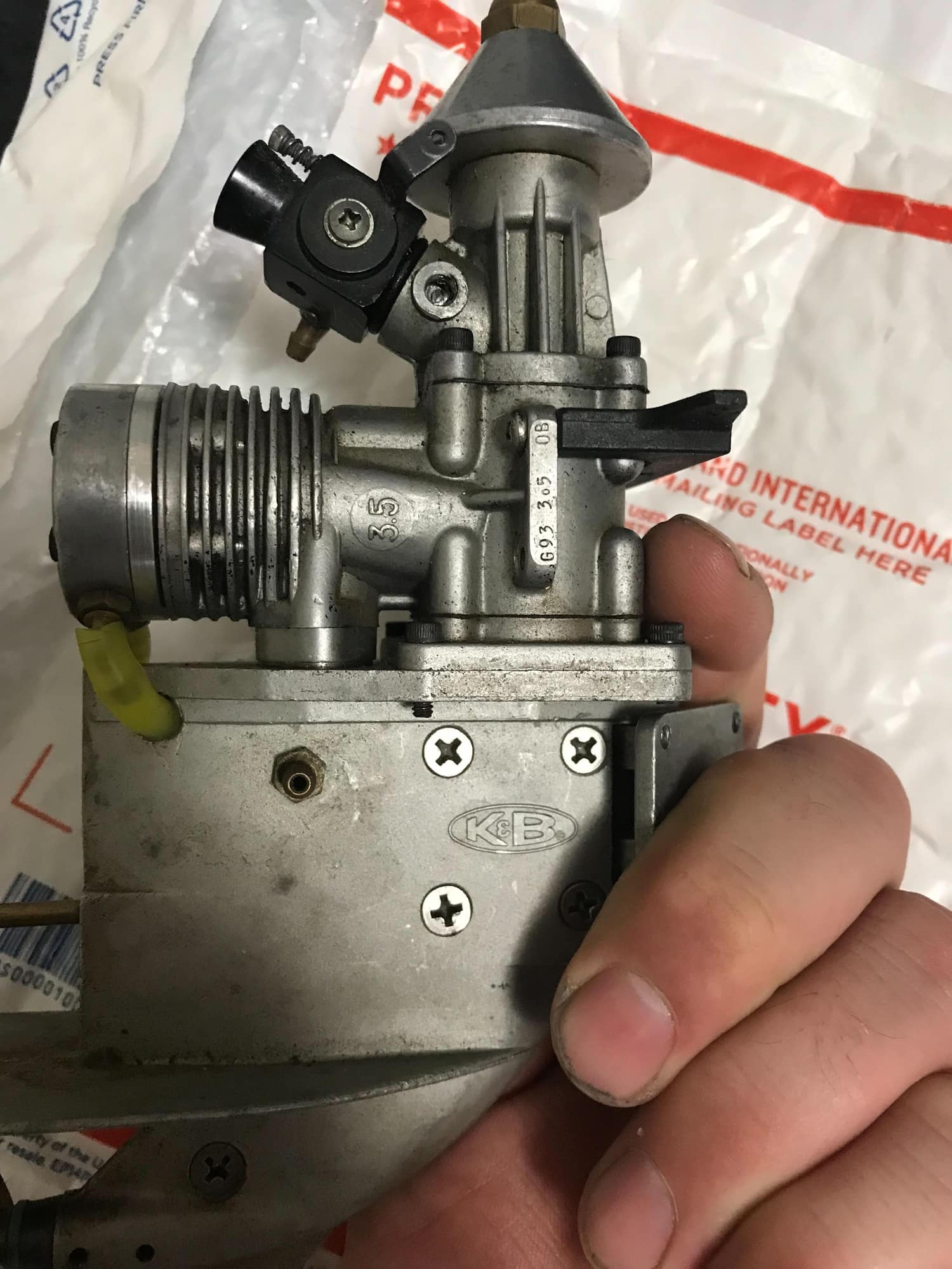
No but seriously, I need some guidance on the build I am doing. I have an older 80's K&B 3.5 Engine. I thought it would look really cool and neat on a 29.5" carbon fiber hull. Also, the motor is on a swivel and has placement for connecting a steering system which is quite simple since it would just be a servo connected directly to the motor by a rod making the motor physically move for steering. I have lots of experience with RC Nitro cars and a little bit with planes but zero with RC boats.
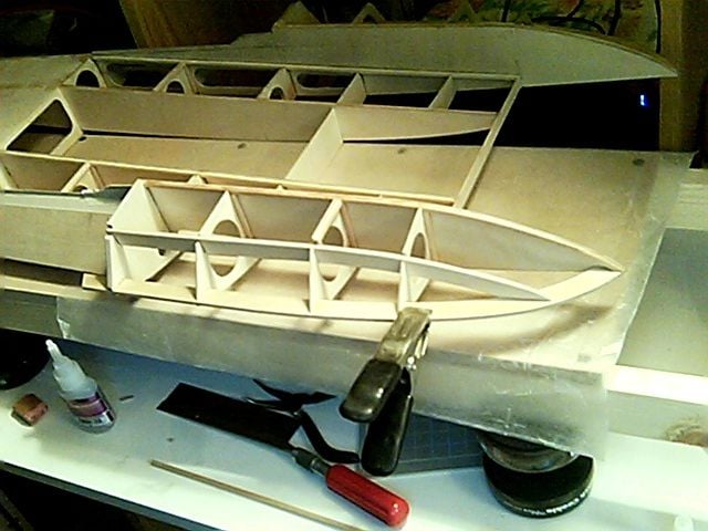
So question one, the carbon fiber looks a bit thin, should I reinforce the inside with some fiber glass? I seen another forum about it a few years ago when I bought all this stuff but yet to configure it all obviously. I seen someone painting the fiberglass spread stuff all over on the inside of the hull. Should I do this?
Question two, will this 3.5 K&B be decent power for this boat? If so how do I got about mounting it? Mainly meaning how far below the hull should my prop be? I was going to 3D print a rubber motor mount to place between the swivel on the motor and the hull of the boat, just so that there was some cushion there and wouldn't crack or break the carbon fiber hull over time.
These are really my main concerns, I design and 3D print stuff all the time so making mounts for every thing to go in the hull shouldn't be an issue for me. I just want to make sure that when I have the motor mounted to the boat, that's its in the correct spot the first time so I'm not drilling unnecessary holes in my boat.
No but seriously, I need some guidance on the build I am doing. I have an older 80's K&B 3.5 Engine. I thought it would look really cool and neat on a 29.5" carbon fiber hull. Also, the motor is on a swivel and has placement for connecting a steering system which is quite simple since it would just be a servo connected directly to the motor by a rod making the motor physically move for steering. I have lots of experience with RC Nitro cars and a little bit with planes but zero with RC boats.
So question one, the carbon fiber looks a bit thin, should I reinforce the inside with some fiber glass? I seen another forum about it a few years ago when I bought all this stuff but yet to configure it all obviously. I seen someone painting the fiberglass spread stuff all over on the inside of the hull. Should I do this?
Question two, will this 3.5 K&B be decent power for this boat? If so how do I got about mounting it? Mainly meaning how far below the hull should my prop be? I was going to 3D print a rubber motor mount to place between the swivel on the motor and the hull of the boat, just so that there was some cushion there and wouldn't crack or break the carbon fiber hull over time.
These are really my main concerns, I design and 3D print stuff all the time so making mounts for every thing to go in the hull shouldn't be an issue for me. I just want to make sure that when I have the motor mounted to the boat, that's its in the correct spot the first time so I'm not drilling unnecessary holes in my boat.
 09-18-2021, 07:37 PM
#2

Time for some clarifying questions:
- What type of hull is this CF boat?
- You say the K&B engines can swivel. Is it one of these?
The following users liked this post:
Geakster (09-20-2021)
09-18-2021, 08:13 PM
#3
yeah I ran in to that problem last night. I have another account but I cant get the recovery link to work, it sends it to me but when I click on it, its says the link wasnt valid.....lol I've tried from multiple web browsers.
Any how, yes that photo is the motor I have. that exact build and style.
The hull is "29.5" mono high deep V hull"
I really appreciate the help.
Any how, yes that photo is the motor I have. that exact build and style.
The hull is "29.5" mono high deep V hull"
I really appreciate the help.
09-18-2021, 08:49 PM
#4
Okay, that gives me a place to start.
That style of engine, referred to as an outboard, was normally used on a tunnel hull style boat. That doesn't mean you can't use it, just that it's not normally done.
Now, for a bit of experienced advice on your project:
That style of engine, referred to as an outboard, was normally used on a tunnel hull style boat. That doesn't mean you can't use it, just that it's not normally done.
Now, for a bit of experienced advice on your project:
- Fiber glass won't help strengthen the transom enough to handle the stress from the engine. You will need to install a plywood doubler no less than 1/8th inch thick(3/16 to 1/4 would be better, more than that is overkill) that covers as much of the inside of the transom as possible. You would need to sand the inside of the transom with a medium grit sandpaper to roughen it up and epoxy in the doubler. What you need to remember(and most don't know) is that CF is actually very brittle. Hit something and it can break easier than plain FG will. This is the reason for the transom covering doubler, it spreads the load over as much area as possible.
- Neither the hull nor the engine has any inherent buoyancy. You will need to add flotation to the hull. Your best bets are cut up pool noodles or insulation foam. This can be installed either in the bow, under the deck, or along the hull sides. Either way, it needs to be secured into the hull to prevent sinking in case the hull is damaged. One thing I would avoid is the expanding foam some use. It can actually damage the hull if exposed to heat(bright sun on a warm day for example) as it will cause the foam to expand further. I've seen it blow the deck off a scale hydroplane more than once
- You will need to use a high torque servo to handle the steering. You're servo will have to be able to move the engine weight as well as overcome the force of the water when you turn the boat. I've had handling issues with my 1/8th scale hydroplane when I didn't have a strong enough servo, more than once damaging the boat. A standard servo will be enough for the throttle function.
- With all of the above, you will need to get it all installed in the boat while keeping the balance point at roughly 1/3rd of the hull length from the transom. Further forward can cause the boat to plow or submarine while further back can cause it to hop or blow over
- A word of caution when using a K&B engine. Parts can be hard to come by since K&B was bought by MECOA so, understandably, you won't want to push the engine too hard or you could end up with a "vintage paper weight"
- Almost forgot this one. DON'T PUT ANYTHING BETWEEN THE HULL AND ENGINE!!!!!! The engine works as both the drive and the rudder. To put a vibration absorbing substance between the hull and engine will cause issues with the engine mount holes, the boat's transom and the engine's adjustments required to get it to work well with the hull. Obviously, paint or finishing materials won't be a problem as it has no "give" to it, so it won't allow the engine mount to move, unlike a softer material
Last edited by Hydro Junkie; 09-18-2021 at 09:06 PM.
The following users liked this post:
Geakster (09-20-2021)
09-18-2021, 09:09 PM
#5
so I understand every thing but the doubler part. Is that going to be a sort of brace? I tried looking up photos and I may have the correct idea or be completely wrong lol. I'f I'm correct it would be a sort of brace in the shape of the inside of the boat covering top, bottom and both sides and would be expoied in. I have a cnc machine so I can measure out the inside of the boat and cut it out so it fits nearly perfect. in the example i was looking at there was multiples of these braces 3 or 4 of them work from the nose back to about 1/3 of the way of the boat.
I like the pool noodle idea, I'll have to grab some from the local store before its too late.
I like the pool noodle idea, I'll have to grab some from the local store before its too late.
09-18-2021, 09:42 PM
#6
A doubler is a piece of material laminated to another piece of material to increase the strength of the second piece. Let me give you an example of how this works, using your boat hull and a 1" ball bearing:
Hope that makes sense
- You glue the ball bearing on a table top.
- After the glue dries, place the rear(transom) of your boat on the ball bearing and push against the bearing with the force being applied to the boat's nose. If you look at the transom, from above, you will see that it is pushed inward with the furthest place in being where the ball is in contact with the transom and the amount of deflection decreases as you move toward the sides, bottom and deck
- Now, take the boat off of the bearing and epoxy a piece of ply onto the inside of the transom. We're not talking running the length of the boat, only along the inside of the transom. After the epoxy has had a full day or two to cure, we repeat the process from the previous step.
- When pushing down on the boat's nose, the transom will be stiffer, not allowing the inward deflection. In fact, the only way the transom will bend is if the plywood, epoxy or CF fails.
Hope that makes sense
The following users liked this post:
Geakster (09-20-2021)
09-18-2021, 10:39 PM
#7
Ahhhhh its a much simpler fix then what I was imagining lol not to mention on the complete other side of the boat then what I was thinking. I'm just not used to the terms yet. But I'm pretty sure I understand now. Basically I'm going to make the back of the boat (Transom) thicker by adding another wall to it essentially, to keep it from flexing like you were describing. This is even easier then what I was thinking since this is an easily accessible area. I could definitely see how the motor could cause this area to break and flex now that you point it out. So this should be the only part I reinforce? when put the hull up to the light, its pretty thin and you can see light right thru it. I know they should be lite weight I just spent a decent amount of money on it and don't want it to blow apart haha. I just want every thing to be as perfect as possible for what I'll be capable of on my first build.
Last edited by Geakster; 09-18-2021 at 11:11 PM.
09-18-2021, 11:19 PM
#8
I found this motor mount on ebay "Prather style Adjustable K&B 3.5 Outboard Motor Engine Mount MECOA PRA-5190"
Should I use this mount so that I have some room to adjust the motor?
Should I use this mount so that I have some room to adjust the motor?
09-19-2021, 12:18 AM
#9
I'm glad that made sense and didn't come across as condescending. Many first timers come into the forum with preconceived ideas on how things should be and, if they are told otherwise, they leave. Some of the time it's due to the way the person answering the question comes across, others because they think what they see on the internet or that what they think they know from other areas of the R/C world is all they need to know . I've been in the R/C community for almost 40 years and will be the first to say I don't know everything. With that all said, I'm going to be limited on how much I can help you. I work primarily with plywood hydroplane hulls I build from plans so I deal with a whole different animal. I do know that others will probably chime in as well and some are well versed in vee hulls and/or outboards
Enough on all of that. I think you will find that boats have more in common with planes than with cars or buggies. Like a plane, the boat requires balancing as mentioned earlier. This is the first spot I am limited on. As I said in a previous post, you will want to have the boat balance at roughly 9-10" forward of the transom. I know the boat also needs to be balanced left to right to prevent excessive rolling. You want the boat to roll in while turning toward the direction of the turn but not when going straight. With an inboard boat, you can adjust the weight to one side or the other where you locate the radio gear and water resistant box it's mounted in, the fuel tank, etc. Not sure how to do this with an outboard motor.
You were wondering about strengthening the hull with FG. Not sure it's going to need that but what you might want to look at is adding internal framing such as what I use in my hydroplanes.
The following users liked this post:
Geakster (09-20-2021)
09-19-2021, 10:23 AM
#10
You've been an amazing help and have already helped me rethink my approach to this project and have shed light on areas I may not have thought of my self. I very much appreciate it. I like to do things correctly the first time around so I'm going to continue to research for another week or two before I start modifying the hull in any way.
For now I will prolly just design the transom support on the computer and print it out and make sure it fits nice and snug all the way around the back. Do you think it would be much difference from printing it out on a 3D printer vs cutting it out of plywood for the transom support? I have a "polysmoother" machine that I can put 3D printed parts in to and it smooths out the 3D printed ridges with a chemical process slightly melting every thing together in to a solid piece that looks much like it was to come from a store rather then made on a 3D printer.
I'm going to also start designing the internal braces from the nose down a bit. I'm not going to mount any thing together just yet until I get a rough estimate on where every thing will need to go as plans can always change. I have to order some more parts and weigh them out to kind of plan every thing to balance as you were saying. So I need to get fuel tank, servos, batteries etc and weigh them to figure out their place in the boat.
Again, I really appreciate all the information and help!
09-19-2021, 12:59 PM
#11
To the question on 3D printing vs ply, it really depends on the material you print it from. If the material has more than a slight flex to it, I would say don't use it. You have to remember, the boat was designed for an inboard engine, not an outboard, so the transom is going to be fairly weak. Even as an inboard, you would still need to install a doubler to handle the rudder and strut/stinger stresses
The following users liked this post:
Geakster (09-20-2021)
09-20-2021, 12:41 AM
#12

Join Date: Jul 2007
Location: Blackpool Lancs, UNITED KINGDOM
Posts: 1,432
Likes: 0
Received 32 Likes
on
32 Posts
If the printed item is at least as strong as the ply and can be laminated onto the transom surface as well as the ply, it will work. If not, no, it won't. Ply tends to be much stronger than the material that is made from suggests. Giving it a coat of epoxy or similar to mount it and waterproof it strengthens it.
I imagine that mounting a printed plate would not have that effect, but it depends on the type and thickness of the plastic used. And the actual design - a ribbed plate with the ribs in the right place "might" be both stronger and more reliable, but does depend on knowing what the likely stress points are going to be before design happens.
I imagine that mounting a printed plate would not have that effect, but it depends on the type and thickness of the plastic used. And the actual design - a ribbed plate with the ribs in the right place "might" be both stronger and more reliable, but does depend on knowing what the likely stress points are going to be before design happens.
The following users liked this post:
Geakster (09-20-2021)
09-20-2021, 04:08 PM
#13
Yeah I'm just going to have the cnc machine cut out plywood in the same shape as the transom. I Know its a simple couple cuts but I'm not the greatest with cutting wood directly with a hand held tool, at least not to the perfection I'd want. its really just easier to use the plywood then to overthink a simple solution, which I can have a habit of doing when I want some thing to look professional. I'll just paint it black or maybe even hydro dip it just to make it match the carbon fiber. I'm willing to spend a little more and work a little longer if its going to make the boat look really clean inside and out.
Last edited by Geakster; 09-20-2021 at 04:11 PM.

 09-24-2021, 05:31 AM
#18
Member
Mounting up and drilling carbon fiber is a science. Read up about it before you go willy nilly.
https://www.corrosionpedia.com/galva...olymers/2/1556
https://www.corrosionpedia.com/galva...olymers/2/1556
The following users liked this post:
Geakster (09-24-2021)
09-24-2021, 05:37 AM
#19
Member
Okay, that gives me a place to start.
That style of engine, referred to as an outboard, was normally used on a tunnel hull style boat. That doesn't mean you can't use it, just that it's not normally done.
Now, for a bit of experienced advice on your project:
That style of engine, referred to as an outboard, was normally used on a tunnel hull style boat. That doesn't mean you can't use it, just that it's not normally done.
Now, for a bit of experienced advice on your project:
- Almost forgot this one. DON'T PUT ANYTHING BETWEEN THE HULL AND ENGINE!!!!!! The engine works as both the drive and the rudder. To put a vibration absorbing substance between the hull and engine will cause issues with the engine mount holes, the boat's transom and the engine's adjustments required to get it to work well with the hull. Obviously, paint or finishing materials won't be a problem as it has no "give" to it, so it won't allow the engine mount to move, unlike a softer material
09-24-2021, 07:32 PM
#20
I have multiple types of 3D printers that are capable of all sorts of different materials between them. Would I want to make some thing out of a rubber to cushion between the hull and the mount? or would I want to make it out of some thing like plastic that has some give to it?
09-24-2021, 08:28 PM
#21
NEITHER ONE!!!
The reason Birdo said to use SS(short for Stainless Steel) is, if I'm reading him correctly, because the stock aluminum mount could flex and crack. Stainless steel won't flex or crack like the stock aluminum, so it's not an issue. Likewise, when I said to not put anything between the engine mount and hull, it was for the same reason, the hull isn't strong enough to handle the stress. I was, however, not aware of the mount being made from aluminum. If anything gets placed between the hull and mount, I would assume Birdo is saying it has to be solid and not able to bend or flex. I'm sure he will correct me if I'm wrong
The reason Birdo said to use SS(short for Stainless Steel) is, if I'm reading him correctly, because the stock aluminum mount could flex and crack. Stainless steel won't flex or crack like the stock aluminum, so it's not an issue. Likewise, when I said to not put anything between the engine mount and hull, it was for the same reason, the hull isn't strong enough to handle the stress. I was, however, not aware of the mount being made from aluminum. If anything gets placed between the hull and mount, I would assume Birdo is saying it has to be solid and not able to bend or flex. I'm sure he will correct me if I'm wrong
The following users liked this post:
Geakster (09-25-2021)
09-25-2021, 05:02 AM
#22
Member
Carbon Fiber in contact with Aluminum will cause big time corrosion. Carbon Fiber conducts electricity, so they're going to fight for electrons.
That KB engine has a pivot, where the mount and engine meet. You could re-create the aluminum transom mount in Stainless Steel or put a piece of stainless between the hull and mount. Make sure you use Stainless bolts.
I'm saying Carbon Fiber doesn't work well with certain metals. If you see Carbon fiber in contact with Aluminum, there usually fiberglass in between to isolate it. Fiberglass looks clear, so it can be hard to tell.
I wouldn't use anything 3d printed with that motor. Those things rip. It's been 20 years since I've seen a tunnel hull running with a 3.5 KB on it. I don't trust anything 3d printed....they're meant for prototyping. Change my mind.
Last edited by birdo; 09-25-2021 at 05:06 AM.
The following users liked this post:
Geakster (09-25-2021)
The following users liked this post:
Geakster (09-25-2021)
09-25-2021, 11:27 PM
#24
I appreciate this information. I'll do as you recommend as I know you all have much more experience with this stuff....that's why I'm here asking you pros all the questions. 
As for the 3D printers only being for prototyping I'd have to (personally) disagree on that. I have a few 3D printed drones, 3D printers made from 3D printed parts, Molds that I make with the 3D printer to make various objects etc...the more 3D printing is around the more materials are created to do various different things but understanding the limits of what your trying to achieve is important.
A lot of my work with the printers is to make the object I intend to create on the printer after I have designed it on CAD program, then mold it and use the mold to recreate the object in a new material that is best suited for the application it is intended for.
with all that being said, my cnc machine is made completely from conduit metal, roller blade bearings and....3D printed parts. obviously the machine has its limits, mainly being a snail compared to a all metal cnc machine. but I can cut/mill wood, aluminum and even a little steel on this machine that was built for under $500. cutting steel is slow....really slow but it can do it with reasonable tolerance.
If you get bored check out the MPCNC Primo, AKA the "Mostly printed CNC Machine" its a surprisingly useful machine for its low costs. A quick google will bring it up as it has a pretty decent size community behind it.
Again thanks for everyone's knowledge and help on this build, I definitely wouldnt be able to accomplish this with out yall.
Last edited by Geakster; 09-25-2021 at 11:30 PM.
10-04-2021, 01:58 PM
#25


I've never liked the Prather OB motor mount, too many short bolts to deal with and hard to adjust, the Du-Bro mount was a lot better.
The transom on that mono may be a little shallow to hang an OB on. There are kits if you want to build a tunnel boat. ML Boatworks is one.
The transom on that mono may be a little shallow to hang an OB on. There are kits if you want to build a tunnel boat. ML Boatworks is one.