


Sailplane Wing Design Round II
 06-02-2012, 03:19 AM
#26
Member
Newbie question: It looks like essentially all of the work to strengthen the wing is aimed at the spar. Under normal flight loads (that is, when not crashing into things), is it fair to say that's the only part that really matters?
In other words, the accident involving wing 1 came in normal flight when the wing folded at an inboard piece. If the spar had been of sufficient strength to hold, might some other part of the wing have failed?Or is the spar bearing essentially all of the flight loads? Is there no point in strengthening ribs (for example) beyond just normal good construction?
(assume I'm not talking about failures of hinges or other control surface moving parts).
I ask because I was kind of amazed to see the "Continuous Webbing - Split Ribs" idea.
 06-02-2012, 08:20 AM
#27
Senior Member
Join Date: Jan 2011
Location: Cody,
WY
Posts: 294
Likes: 0
Received 0 Likes
on
0 Posts
BTW, using the vertical grain balsa shear web will not strengthen the web if you use a thru-rib design. The rib will have the weakest shear strength and a shear failure will begin there. You could use horizontal grain balsa between the ribs (maybe even foam), which will still be stronger than the rib in shear.
In reality, I don't think that you will be generating enough stress to cause the shear web to fail. The key will be keeping the caps firmly interfaced with web (wrapping).
I also think that your spar caps are larger than necessary if they are wrapped.
In reality, I don't think that you will be generating enough stress to cause the shear web to fail. The key will be keeping the caps firmly interfaced with web (wrapping).
I also think that your spar caps are larger than necessary if they are wrapped.
06-02-2012, 10:59 AM
#28

Thread Starter

Join Date: Feb 2012
Location: Fairfield, CT
Posts: 416
Likes: 0
Received 0 Likes
on
0 Posts
ORIGINAL: sylvie369
...It looks like essentially all of the work to strengthen the wing is aimed at the spar. Under normal flight loads (that is, when not crashing into things), is it fair to say that's the only part that really matters?..
...It looks like essentially all of the work to strengthen the wing is aimed at the spar. Under normal flight loads (that is, when not crashing into things), is it fair to say that's the only part that really matters?..
When I first looked at split rib designs I thought, "well that's no good, the front & rear of the wing will just fall off". I'm still not 100% clear why this doesn't occur but I'm guessing the top & bottom sheeting may play a role. Also one rib butt-joined to the spar is probably quite weak but tied together with the rest of them via the LE or TE I guess they help support each other? My last thought is if the ribs are epoxied to the spar, that bond is stronger than the rib itself, so if its going to break, its the rib that'll fail, not the joint. I'm just guessing though *shrug*.
ORIGINAL: wyowindworks
...In reality, I don't think that you will be generating enough stress to cause the shear web to fail...
...In reality, I don't think that you will be generating enough stress to cause the shear web to fail...
06-02-2012, 11:02 AM
#29
Thread Starter
Join Date: Feb 2012
Location: Fairfield, CT
Posts: 416
Likes: 0
Received 0 Likes
on
0 Posts
Well inspired by BMatthews' excellent suggestions I have a slightly modified plan for my wing-rod joiner section...
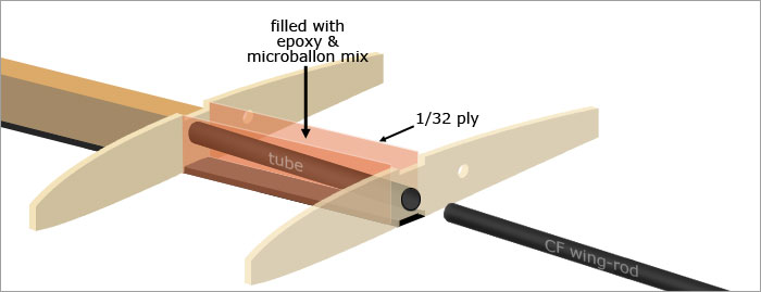
I like this idea because it avoids the hassle of needing to accurately drill holes in hardwood blocks at exacting angles. A nightmare to get right using wood but with Matthews' liquid method, all I need do it place the two wing panels together, insert the tubes & wing-rod & pack in the goop.
I like this idea because it avoids the hassle of needing to accurately drill holes in hardwood blocks at exacting angles. A nightmare to get right using wood but with Matthews' liquid method, all I need do it place the two wing panels together, insert the tubes & wing-rod & pack in the goop.
06-02-2012, 11:56 AM
#30
Senior Member
ORIGINAL: Nodd
I like this idea because it avoids the hassle of needing to accurately drill holes in hardwood blocks at exacting angles. A nightmare to get right using wood but with Matthews' liquid method, all I need do it place the two wing panels together, insert the tubes & wing-rod & pack in the goop.
I like this idea because it avoids the hassle of needing to accurately drill holes in hardwood blocks at exacting angles. A nightmare to get right using wood but with Matthews' liquid method, all I need do it place the two wing panels together, insert the tubes & wing-rod & pack in the goop.
The technique you've pictured has been around for a very long time. The rods used to be piano wire. Back then there was tubing from the rack to fit whatever size rod you figured was appropriate. It's quite an easy job once you've worked out handling the process.
Keep in mind that up until CF reared it's expensive head, we used spruce spars and balsa webbing. Once we got your component sizes worked out, wing failures were really not a problem. Sometimes having a stiffener that is too stiff causes problems. It is significant that your wing failure appears to have happened during what sounds like normal flight.
BTW, it's a good idea to pick up a handfull of ordinary wooden dowels to have on hand when doing the work. They make quick and easy end plugs. Gap filling CA seals the plug in a heartbeat and you'll have no worries the 'liquid' might lock the rod in the tube.
06-02-2012, 12:07 PM
#31
Senior Member
ORIGINAL: Nodd
I like this idea because it avoids the hassle of needing to accurately drill holes in hardwood blocks at exacting angles.
I like this idea because it avoids the hassle of needing to accurately drill holes in hardwood blocks at exacting angles.
06-02-2012, 08:21 PM
#32
Thread Starter
Join Date: Feb 2012
Location: Fairfield, CT
Posts: 416
Likes: 0
Received 0 Likes
on
0 Posts
Yeah I recall flying gliders & whatnot back in the '80s using piano wire wing-rods. I don't think I flew with the same amount of dihedral twice LOL. Worked out nicely though, the gliders got more stable with each high-start launch :-P
I'm not really surprised that my old wing failed during normal flight. Since discussing it here online in excruciating detail I've realized it had several major design flaws including a weak C shaped spar, poorly attached webbing, gappy butt-joined sheeting & areas of high strength that ended abruptly causing stress points. Failure was inevitable. I'm chocking it up to a learning experience & trying not to dwell on the what ifs. New wing, new design, moving on...
Good call on the top & bottom filler pieces to displace some of the microballoon goop around my wing tubes. That'll save me some glue. I'll probably use your tube plugging tip too. Much appreciated, thanks.
06-02-2012, 09:32 PM
#33


Join Date: Oct 2002
Location: Chilliwack, BC, CANADA
Posts: 12,425
Likes: 0
Received 22 Likes
on
19 Posts
The trick about drilling precision holes in two different wing panels is what led me to use the goop and tubing method in the first place. And yeah, there's certainly no foul at all about packing much of the space with more balsa to limit the amount of goop required.
To confirm DaRock's ideas on spruce vs carbon I've got a 2meter glider which was converted with a new fuselage to electric motor launch some years back. The airfoil is an Eppler 201 which is a little thicker than most at 12.5'ish percent. But this two meter model has lived through winch launches and a couple of rather nasty pull outs all with nothing more than carefully selected 1/8x1/4 spruce caps top and bottom and double webbing front and back. The key was to use thin ply for the first few rib bays and very rock hard balsa for the next few, then hard balsa and so on out to the tips where lighter balsa did the job just fine.
There was this one time when we were flying in some rather washing machine like air. I was trying to core a nasty tight thermal. I'd gotten up to around 400 feet when it suddenly stepped sideways and went into a vertical dive. Full up elevator did nothing at all. The model very quickly lost 200 or more feet with me holding full up. Suddenly the elevator caught and the model reversed direction in the blink of an eye to straight up vertical. I can't even begin to imagine the G forces that occured during that reversal. But it does show what rather modest amounts of good quality aircraft grade spruce can withstand if you brace and support it correctly.
For the heck of it here's a picture of the model. It's an old RO-8 from a kit. Mind you the kit wood and parts were SOOOO bad that in the end I found I'd bought nothing more than a set of plans and some trailing edge stock. The rest was a total write off. This wing uses a wholely open structure with multi turbulator spars to support the covering and avoid much of the usual sag. This is the pure and original glider version as shown here. I later built a lengthed electric power fuselage for the wings and stabilizer.
06-03-2012, 03:05 AM
#34
Member
ORIGINAL: Nodd
When I first looked at split rib designs I thought, "well that's no good, the front & rear of the wing will just fall off". I'm still not 100% clear why this doesn't occur but I'm guessing the top & bottom sheeting may play a role. Also one rib butt-joined to the spar is probably quite weak but tied together with the rest of them via the LE or TE I guess they help support each other? My last thought is if the ribs are epoxied to the spar, that bond is stronger than the rib itself, so if its going to break, its the rib that'll fail, not the joint. I'm just guessing though *shrug*.
When I first looked at split rib designs I thought, "well that's no good, the front & rear of the wing will just fall off". I'm still not 100% clear why this doesn't occur but I'm guessing the top & bottom sheeting may play a role. Also one rib butt-joined to the spar is probably quite weak but tied together with the rest of them via the LE or TE I guess they help support each other? My last thought is if the ribs are epoxied to the spar, that bond is stronger than the rib itself, so if its going to break, its the rib that'll fail, not the joint. I'm just guessing though *shrug*.
If I'm understanding the discussion properly, part of the issue is spar caps (the CF, in this case) debonding under flight loads from the spruce spar itself, thus leaving the spruce spar to bear the load. And wrapping is aimed solely at keeping that debonding from happening. Correct?
06-03-2012, 07:16 AM
#35
Senior Member
Join Date: Jan 2011
Location: Cody,
WY
Posts: 294
Likes: 0
Received 0 Likes
on
0 Posts
ORIGINAL: sylvie369
If I'm understanding the discussion properly, part of the issue is spar caps (the CF, in this case) debonding under flight loads from the spruce spar itself, thus leaving the spruce spar to bear the load. And wrapping is aimed solely at keeping that debonding from happening. Correct?
If I'm understanding the discussion properly, part of the issue is spar caps (the CF, in this case) debonding under flight loads from the spruce spar itself, thus leaving the spruce spar to bear the load. And wrapping is aimed solely at keeping that debonding from happening. Correct?
06-03-2012, 10:22 AM
#36
Member
My Feedback: (3)
Join Date: Sep 2002
Location: Laramie, WY
Posts: 73
Likes: 0
Received 0 Likes
on
0 Posts
First I would put the main spar at the thickest part of the rib about 25% to 30% of the way back from the leading edge. Instead of doing all the work wrapping a built-up spar, use a CF tube for the spar. A CF tube about 50% diameter of the average wing rib thickness of the wing panel sounds fine. Just cut round holes in the middle of the ribs 25% back from the leading edge. Slip all the ribs on the tube and glue. Then between the ribs on top and bottom of the CF tube glue balsa filler strips to get the spar to the same thickness as the ribs. Sheet the front part of the wing in the “D” tube configuration over lapping the main spar. The carbon fiber tube wing spar is also use as the wing jointer tube. This type of build up is easy to do, very strong and light, it will also flex under heavy loads without snapping.
06-03-2012, 11:34 AM
#37
Senior Member
Join Date: Jan 2011
Location: Cody,
WY
Posts: 294
Likes: 0
Received 0 Likes
on
0 Posts
The downside to the tube spar is that it yeilds a much lower specific stiffness (less stiffness for more weight) than cap/web spar. With a tube you have the least amount of carbon in area of the greatest stress. You also end up with carbon (heavier than balsa) in areas of low stress. With a cap/web spar you end up putting a majority of the carbon in the areas with the greatest stress and have lighter materials in areas with the least stress.
06-03-2012, 01:56 PM
#38
Thread Starter
Join Date: Feb 2012
Location: Fairfield, CT
Posts: 416
Likes: 0
Received 0 Likes
on
0 Posts
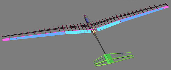
When rethinking my wing design after the crash I spent some time researching sailplanes that use CF tubes for spars. Here's one design I was studying...
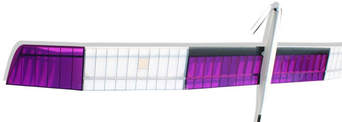
I really like the simplicity of the spar, was very tempted to take that route with my new wing. For now though I don't want to abandon the cap-spar/webbing option. I feel I need to get that right before moving on or it'll bug me to no end. I can see myself having a go at a CF tube spar wing in the future though. I like the idea a lot. Here's a better view of the spar...

I suppose there's no reason why you couldn't progressively step down the size of a CF tube spar as you move out towards the tips. Another approach might be to use tapered CF tubing like you see for sale as tail-booms. Anyway I don't want to stray too far from my current design but yeah I'm a fan of using a tube as a spar. They say round is good. Thanks for the suggestion.
I really like the simplicity of the spar, was very tempted to take that route with my new wing. For now though I don't want to abandon the cap-spar/webbing option. I feel I need to get that right before moving on or it'll bug me to no end. I can see myself having a go at a CF tube spar wing in the future though. I like the idea a lot. Here's a better view of the spar...
I suppose there's no reason why you couldn't progressively step down the size of a CF tube spar as you move out towards the tips. Another approach might be to use tapered CF tubing like you see for sale as tail-booms. Anyway I don't want to stray too far from my current design but yeah I'm a fan of using a tube as a spar. They say round is good. Thanks for the suggestion.
06-03-2012, 03:05 PM
#39
Member
My Feedback: (3)
Join Date: Sep 2002
Location: Laramie, WY
Posts: 73
Likes: 0
Received 0 Likes
on
0 Posts
Hi Nodd
After thinking about your wing I do see a problem. It seems that you’re spacing the ribs too far apart. I think that your doing this to save weight but what you’re doing is remove strength from the wing and adding the weight right back on to the spar. The ribs “do” add strength to the wing by supporting the stress-skin, whether it is plastic iron-on or balsa sheet. The bigger the space between the ribs, the easier the stress-skin between the ribs can be displaced out of shape, in turn collapsing the stress-skin and breaking the wing. Don’t forget about the strength the shin adds to the wing when it is properly supported. I like the carbon tube idea when spacing the ribs far apart. Just saying
After thinking about your wing I do see a problem. It seems that you’re spacing the ribs too far apart. I think that your doing this to save weight but what you’re doing is remove strength from the wing and adding the weight right back on to the spar. The ribs “do” add strength to the wing by supporting the stress-skin, whether it is plastic iron-on or balsa sheet. The bigger the space between the ribs, the easier the stress-skin between the ribs can be displaced out of shape, in turn collapsing the stress-skin and breaking the wing. Don’t forget about the strength the shin adds to the wing when it is properly supported. I like the carbon tube idea when spacing the ribs far apart. Just saying
06-03-2012, 03:35 PM
#40
Thread Starter
Join Date: Feb 2012
Location: Fairfield, CT
Posts: 416
Likes: 0
Received 0 Likes
on
0 Posts
I don't know, a 3½" rib spacing doesn't strike me as all that far apart but I hear ya.
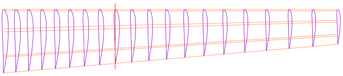
My current thinking is I may start out with closely spaced ribs at the root & steadily increase the spacing exponentially as we approach the tip. So in the center of the wing the ribs might be just an inch apart & then by the time we get to the tips there maybe as much as five inches between them. Its all part of my new "taper the strength" philosophy. The other good thing about that is you end up with more or less the same rib count as linear rib spacing. The complicated part is figuring out the size & spacing of each rib but that's what the computer is for.
My current thinking is I may start out with closely spaced ribs at the root & steadily increase the spacing exponentially as we approach the tip. So in the center of the wing the ribs might be just an inch apart & then by the time we get to the tips there maybe as much as five inches between them. Its all part of my new "taper the strength" philosophy. The other good thing about that is you end up with more or less the same rib count as linear rib spacing. The complicated part is figuring out the size & spacing of each rib but that's what the computer is for.
06-03-2012, 07:38 PM
#41
Thread Starter
Join Date: Feb 2012
Location: Fairfield, CT
Posts: 416
Likes: 0
Received 0 Likes
on
0 Posts
A HUGE THANK YOU to everyone for helping me redesign this wing.
Enough talk though, now its time to build, woohoo!
I spent a few hours tonight working up the new design in my CAD software. Here's a few teaser views...
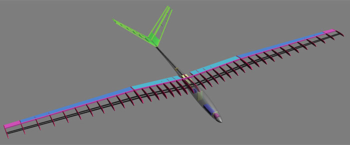
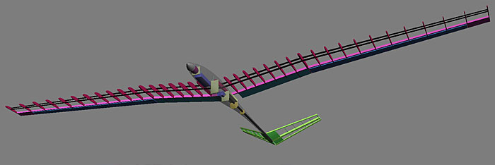
I'll probably order the CF & wood early this week, can't wait to get started building or should I say re-building :-)
Enough talk though, now its time to build, woohoo!
I spent a few hours tonight working up the new design in my CAD software. Here's a few teaser views...
I'll probably order the CF & wood early this week, can't wait to get started building or should I say re-building :-)
06-04-2012, 12:02 PM
#42
Thread Starter
Join Date: Feb 2012
Location: Fairfield, CT
Posts: 416
Likes: 0
Received 0 Likes
on
0 Posts
Check's in the Mail!
I ordered the supplies for the new wing, should have those later this week.
Some of you maybe interested in how much scratch building in wood costs. Here's my shopping list for the new wing...
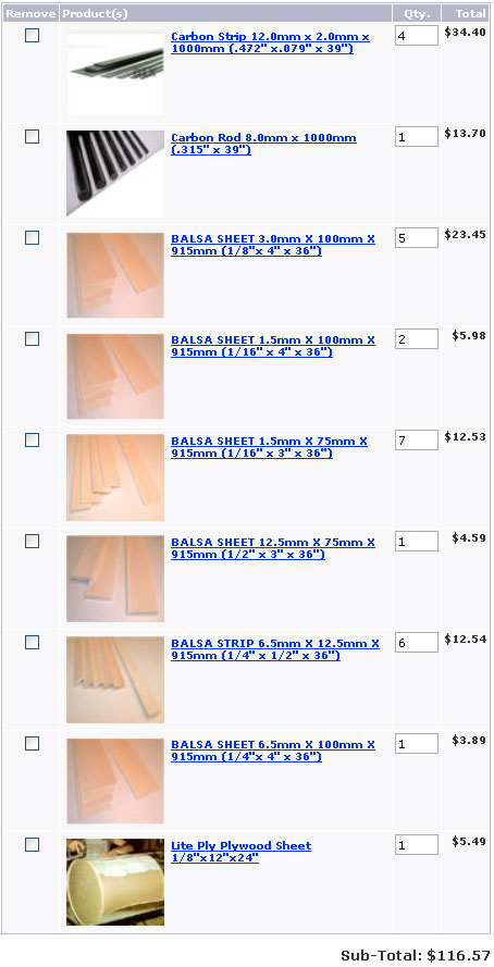
This order was placed with RCFoam.com. I've dealt with them before & like their level of service & products. There's lots of other online retailers for the this stuff too. Oh & of course don't forget to support your LHS (local hobby shop), I try to buy my parts there when I can.
I ordered the supplies for the new wing, should have those later this week.
Some of you maybe interested in how much scratch building in wood costs. Here's my shopping list for the new wing...
This order was placed with RCFoam.com. I've dealt with them before & like their level of service & products. There's lots of other online retailers for the this stuff too. Oh & of course don't forget to support your LHS (local hobby shop), I try to buy my parts there when I can.
06-11-2012, 10:07 AM
#43
Thread Starter
Join Date: Feb 2012
Location: Fairfield, CT
Posts: 416
Likes: 0
Received 0 Likes
on
0 Posts
Balsa in a Box
The wood & CF for my new wing arrived today, woohoo!..
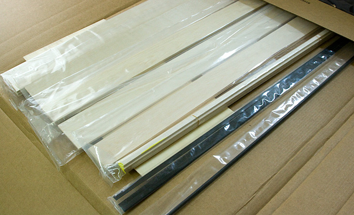
This is the second time I've ordered from RCFoam.com. Once again I'm impressed with the packaging & the quality of the wood. The carbon fiber looks real nice too.
Now that I have the parts in hand I can finalize my plans. I wanted to wait until I could take actual real world measurements from the wood & CF. Unlike the first, this wing will be tight & precise. Here's an initial layout for the ribs...
I'm headed off on a fishing trip this week so won't be able to build until later in the week, will post more when I get back.
The wood & CF for my new wing arrived today, woohoo!..
This is the second time I've ordered from RCFoam.com. Once again I'm impressed with the packaging & the quality of the wood. The carbon fiber looks real nice too.
Now that I have the parts in hand I can finalize my plans. I wanted to wait until I could take actual real world measurements from the wood & CF. Unlike the first, this wing will be tight & precise. Here's an initial layout for the ribs...
I'm headed off on a fishing trip this week so won't be able to build until later in the week, will post more when I get back.
07-02-2012, 06:40 PM
#44
Thread Starter
Join Date: Feb 2012
Location: Fairfield, CT
Posts: 416
Likes: 0
Received 0 Likes
on
0 Posts
Why no progress?
A quick update, its been a few weeks since my building supplies arrived. Unfortunately they're still sitting on my workbench. I've been a tad distracted by a DLG project but that's almost complete so I should be able to get back to the wing shortly.
Oops!
I just noticed, looking at my supplies, that I only ordered four CF spar-caps. This will be a three part wing so I need a total of six, not four, grumble, grumble, grumble. Turns out my over-site might be one of those happy accidents though...
While poking around the Net looking to order another two 12mm x 2mm CF strips I came across some really cool tapered CF. These strips are 12mm wide & start off 1.5mm thick then taper off to 0.5mm over around a meter. So I ordered four figuring I'll use these for my outboard wing sections, tapering off as we approach the wing-tips. I'll use my non tapered CF for the center wing section.
I'm liking this, should save me some weight as surprisingly, 12mm x 2mm x 1m CF does actually weight a fair amount. Using tapered spar-caps should be pretty slick. Now of course I have to wait for them to arrive. I should be able to get going on the center wing though. We like happy accidents.
07-04-2012, 09:06 AM
#45
Junior Member
My Feedback: (2)
Join Date: Jun 2003
Location: Sterling Hgts.,
MI
Posts: 4
Likes: 0
Received 0 Likes
on
0 Posts
For supporting your wing rod tube, rather than trying to drill a hole at an angle or using the epoxy method, I would use a hardwood wedge over and under the tube with a milled slot to match the O.D. of the tube, epoxy or AC in place then go with your cap and wrap as per your plans. I personally machine a wingrod system that puts the wing rods at the desired dihedral angle and run my wing rods straight up inside the wing 10 to 12 inches. My webs between the spars support the tube and everything is capped and wrapped as is standard. I use a hardened ejector pin for my wing rods. My wing rods are removable from the fuse and are held in place by set screws. My fixtures are made out of aluminum or titanium and attached to the fuse bulkhead thats closest to the rod position. It's way overkill but the system has worked in several sailplanes so far with no issues.
07-06-2012, 07:52 PM
#46
Thread Starter
Join Date: Feb 2012
Location: Fairfield, CT
Posts: 416
Likes: 0
Received 0 Likes
on
0 Posts
Sounds like you have a pretty sweet system going there. I think however, I'm going to stick with my plans to use an epoxy system as that doesn't require any precision machining. At this point I'm all about doing things the easy way & getting this bird back in the air ASAP. I'll keep your over/under wedge system in mind for future builds though, thanks.
07-06-2012, 07:54 PM
#47
Thread Starter
Join Date: Feb 2012
Location: Fairfield, CT
Posts: 416
Likes: 0
Received 0 Likes
on
0 Posts
Construction Begins!
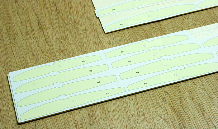
No more delays, its time to get this wing built! Today I started cutting ribs. First I printed them onto 8½ x 11 sheets then contact cemented them to my wood...
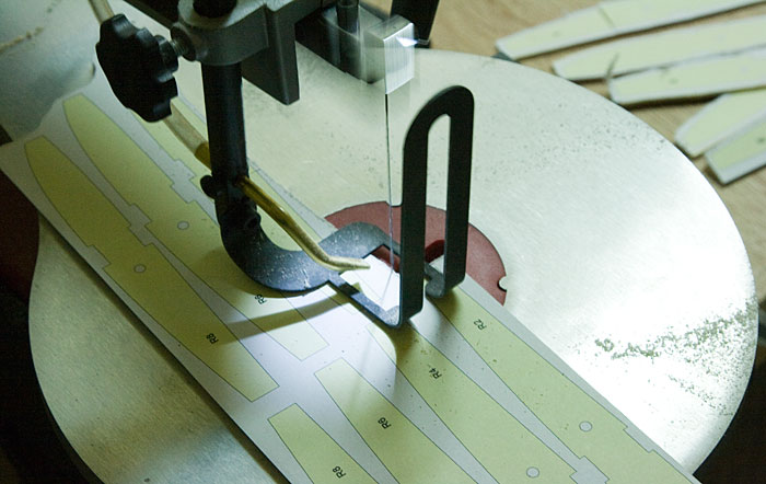
Next I rough cut them on my scroll saw...
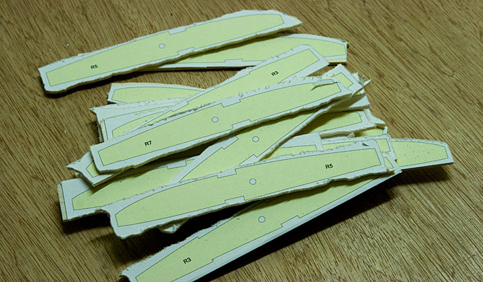
Here's the ribs for the wing center section. At this point they don't need to be accurately cut...
Next I head to the belt sander where the shape is refined...
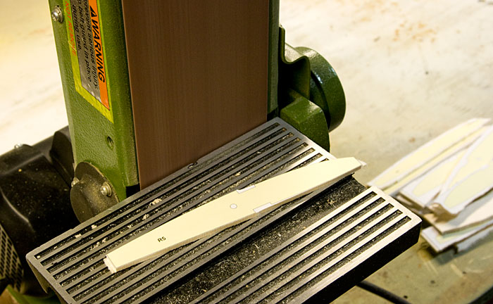
Here's the center wing section rib set. I still need to cut the spar notches & the servo wire holes but its a start...
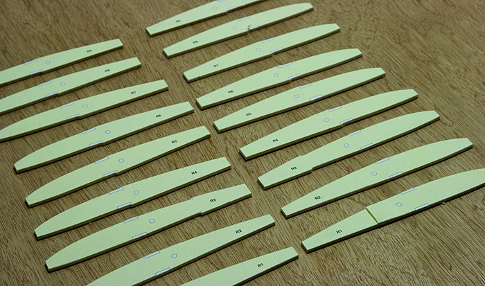
Feels great to be putting this bird back together. Can't wait to have her flying again. Summer is rolling by fast, I want to get back to enjoying her while its still nice out.
No more delays, its time to get this wing built! Today I started cutting ribs. First I printed them onto 8½ x 11 sheets then contact cemented them to my wood...
Next I rough cut them on my scroll saw...
Here's the ribs for the wing center section. At this point they don't need to be accurately cut...
Next I head to the belt sander where the shape is refined...
Here's the center wing section rib set. I still need to cut the spar notches & the servo wire holes but its a start...
Feels great to be putting this bird back together. Can't wait to have her flying again. Summer is rolling by fast, I want to get back to enjoying her while its still nice out.
07-07-2012, 12:48 PM
#48
Join Date: Oct 2002
Location: Chilliwack, BC, CANADA
Posts: 12,425
Likes: 0
Received 22 Likes
on
19 Posts
Nodd, you really need to start slicing your own strip stock from sheet. It reduces the pricing by a LOT! Plus you can select the wood a lot more wisely. Not to mention that you can work with oddball widths if needed. It's truly a win, win, win sort of deal.
07-07-2012, 01:08 PM
#49
Junior Member
My Feedback: (2)
Join Date: Jun 2003
Location: Sterling Hgts.,
MI
Posts: 4
Likes: 0
Received 0 Likes
on
0 Posts
Actually, my first set of spar tube blocks were cut and milled on a Dremel drill press with a guide clamped onto the table. You could just use wedge blocks with no slot and block the tube in with wood then use epoxy and micro baloons to fill in around the tube. You will still be using a short pin for the wing rod so webbing, capping and wrapping will be required. If you don't get a gorilla foot on the winch pedal it may even last a long time. Tapping the pedal is the key with these short wing rods to keep them flying for a very long time.
The build is great by the way. I really like your design and may try your pod and boom design on a plane of my own, if that's alright.
The build is great by the way. I really like your design and may try your pod and boom design on a plane of my own, if that's alright.
07-07-2012, 01:47 PM
#50
Thread Starter
Join Date: Feb 2012
Location: Fairfield, CT
Posts: 416
Likes: 0
Received 0 Likes
on
0 Posts
ORIGINAL: BMatthews
Nodd, you really need to start slicing your own strip stock from sheet. It reduces the pricing by a LOT! Plus you can select the wood a lot more wisely. Not to mention that you can work with oddball widths if needed. It's truly a win, win, win sort of deal.
Nodd, you really need to start slicing your own strip stock from sheet. It reduces the pricing by a LOT! Plus you can select the wood a lot more wisely. Not to mention that you can work with oddball widths if needed. It's truly a win, win, win sort of deal.
ORIGINAL: DrlSgt
Actually, my first set of spar tube blocks were cut and milled on a Dremel drill press with a guide clamped onto the table. You could just use wedge blocks with no slot and block the tube in with wood then use epoxy and micro baloons to fill in around the tube. You will still be using a short pin for the wing rod so webbing, capping and wrapping will be required. If you don't get a gorilla foot on the winch pedal it may even last a long time. Tapping the pedal is the key with these short wing rods to keep them flying for a very long time.
Actually, my first set of spar tube blocks were cut and milled on a Dremel drill press with a guide clamped onto the table. You could just use wedge blocks with no slot and block the tube in with wood then use epoxy and micro baloons to fill in around the tube. You will still be using a short pin for the wing rod so webbing, capping and wrapping will be required. If you don't get a gorilla foot on the winch pedal it may even last a long time. Tapping the pedal is the key with these short wing rods to keep them flying for a very long time.
ORIGINAL: DrlSgt
The build is great by the way. I really like your design and may try your pod and boom design on a plane of my own, if that's alright.
The build is great by the way. I really like your design and may try your pod and boom design on a plane of my own, if that's alright.
Pod Build 1
Pod Build 2