


New Yellow Aircraft Mako (F-16) EDF Project (Full Build)
 12-13-2013, 10:33 AM
#51

Thread Starter

It doesn't take much! A little bit of time, a little bit of money. I would be happy to quote you on an F-15 build. My email is [email protected]
 12-15-2013, 11:12 PM
#52
Join Date: Nov 2013
Location: Fair Oaks, CA
Posts: 144
Likes: 0
Received 0 Likes
on
0 Posts
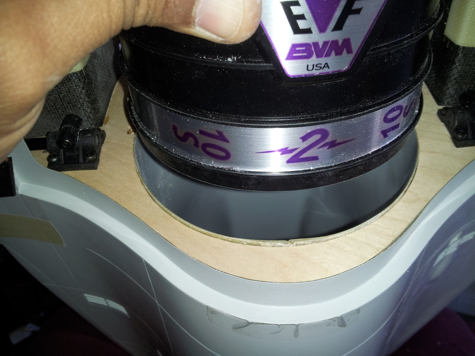
Got a fan ordered for this project now. Found a good deal on a brand new BVM EVF 2 for about $1,000 so we'll give that a whirl. Once Shaun gets the fan, the build should really 'take off!'
12-16-2013, 08:08 AM
#53
Thread Starter
Hi,
Yep, although I'll be posting pics of the [slow] progress so far. All of the internals aft of the rear main bulkhead are installed with the glue curing as of a few minutes ago.
Yep, although I'll be posting pics of the [slow] progress so far. All of the internals aft of the rear main bulkhead are installed with the glue curing as of a few minutes ago.
12-19-2013, 09:34 AM
#55
Thread Starter
Hi,
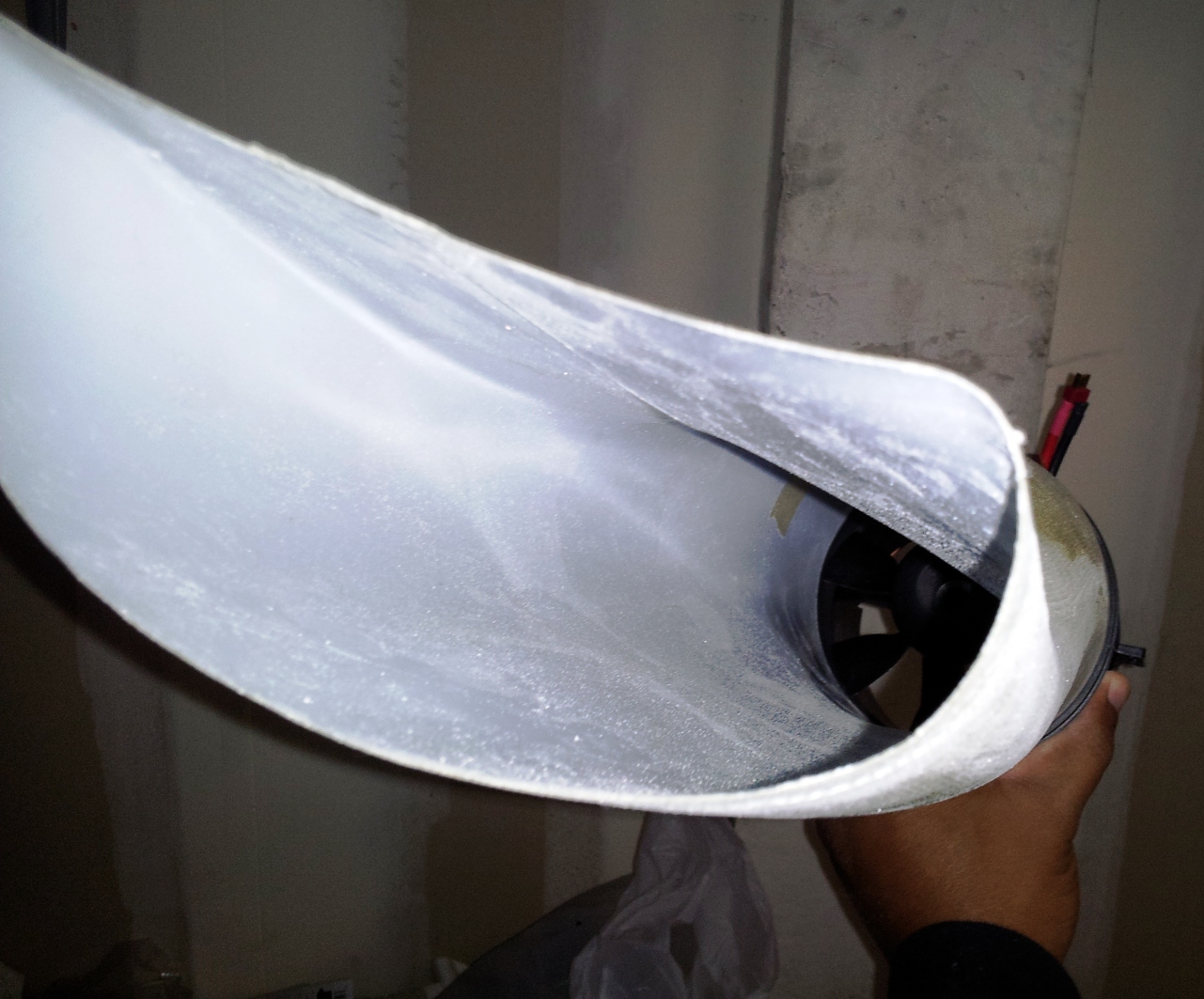
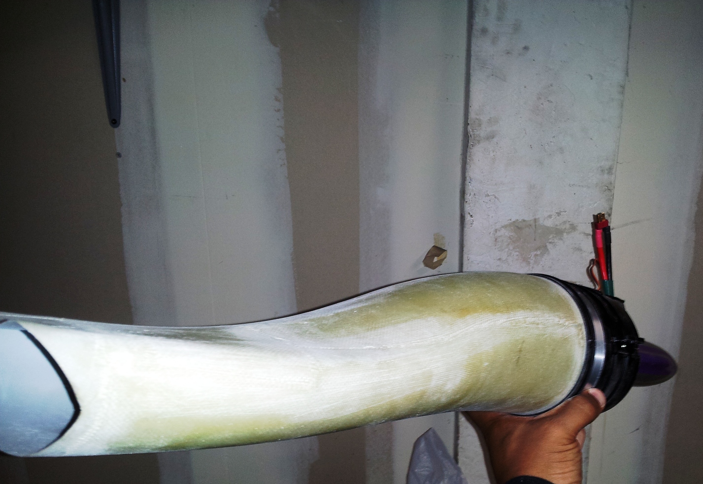
The BVM inlet needs to be reinforced for DF use, otherwise that fan would implode it on the first run-up. I glassed the outside of it with cloth and resin. The top of it will be epoxied to the intake so it doesn't require glass all the way to the front. The stock inlet has some bumps molded in for the steering arm, but the BV inlet does not, so I'm going to have to solve that problem since the steering rubs pretty hard. This BV inlet is quite a bit smoother, though, and should make a decent improvement on performance.


The BVM inlet needs to be reinforced for DF use, otherwise that fan would implode it on the first run-up. I glassed the outside of it with cloth and resin. The top of it will be epoxied to the intake so it doesn't require glass all the way to the front. The stock inlet has some bumps molded in for the steering arm, but the BV inlet does not, so I'm going to have to solve that problem since the steering rubs pretty hard. This BV inlet is quite a bit smoother, though, and should make a decent improvement on performance.
12-20-2013, 08:53 AM
#56
Thread Starter
Hi,
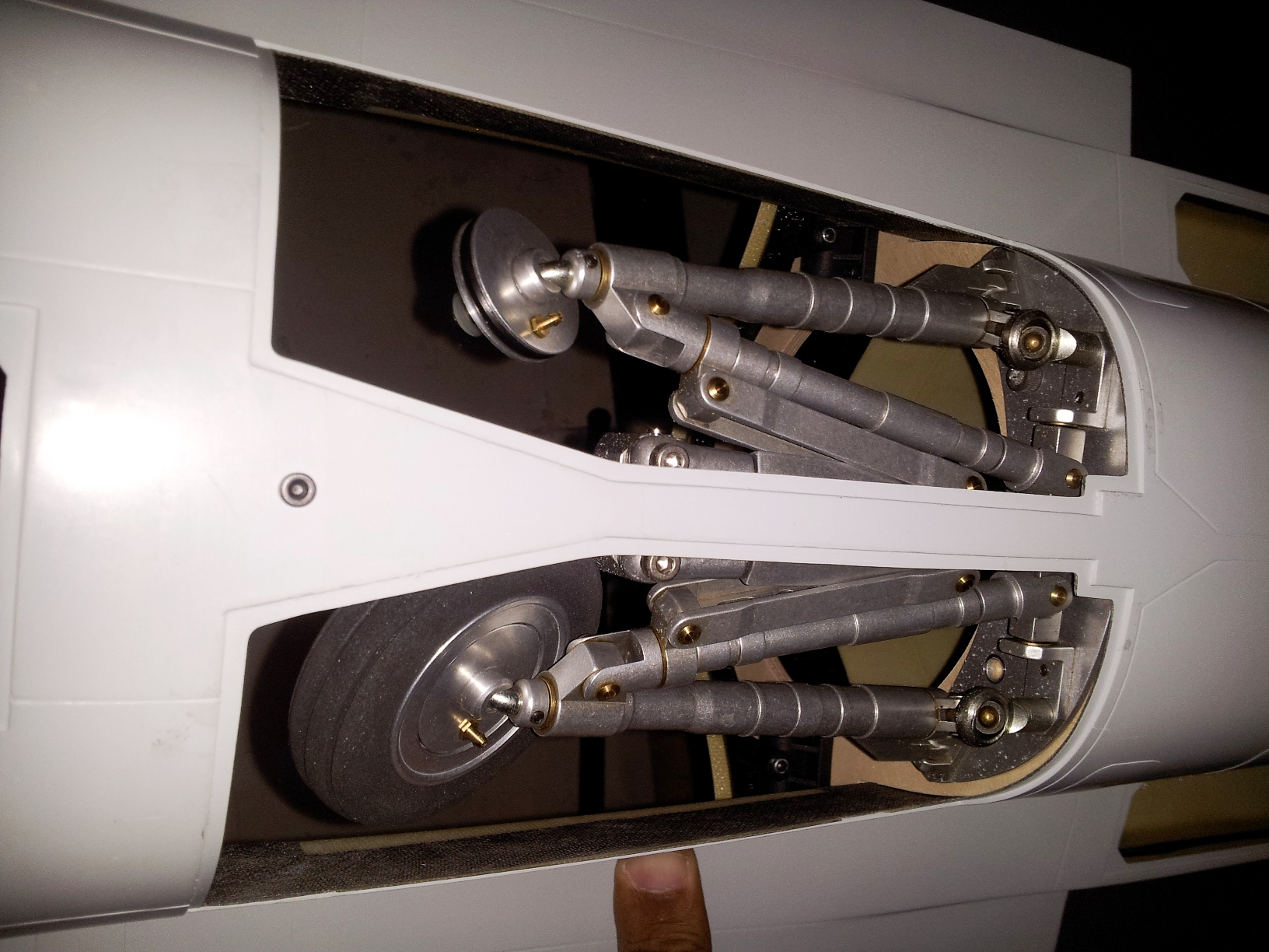
The stock duct has two concave divots molded in on the bottom to clear the main wheels when retracted. I was concerned about this because I'm not using the stock duct (since it's too big for the BVM fan) and I wasn't sure how to modify a mylar tube to accommodate the wheels. It turns out that the smaller diameter of the fan solves the problem on its own. The wheels clear as-is!
The inlet fits into the face of the fan shroud, instead of the other way around. That makes for an even smoother flow to the impeller. It looks like the big fairing is going to be a problem getting in and out of the small hatch, but I'll figure it out.
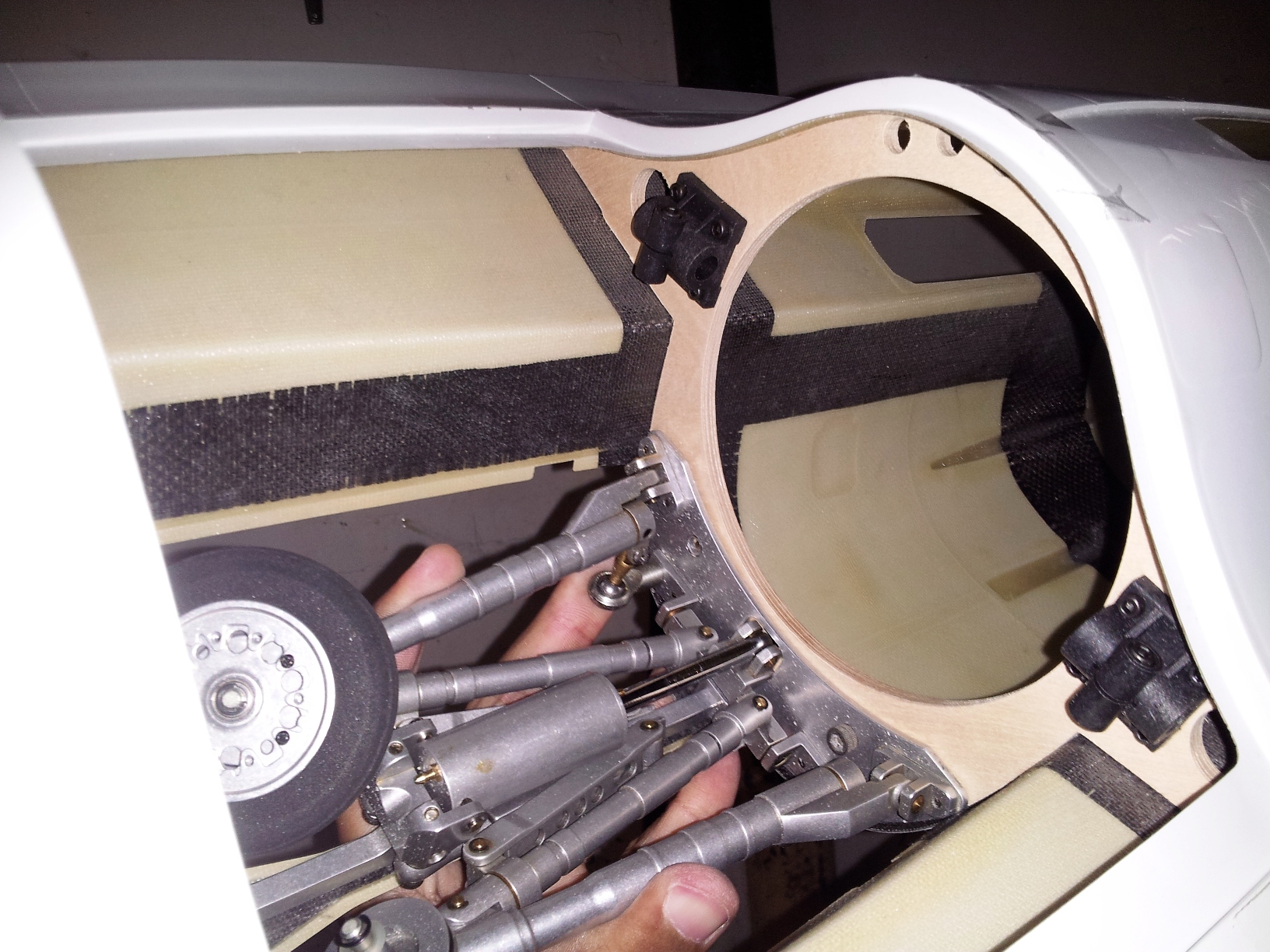
12-20-2013, 10:37 PM
#57
Join Date: Nov 2013
Location: Fair Oaks, CA
Posts: 144
Likes: 0
Received 0 Likes
on
0 Posts
Looking good Shaun! The inlet duct looks pretty smooth, it is a little hard to tell from the picture whether or not you have modified the inlet to clear the landing gear yet.
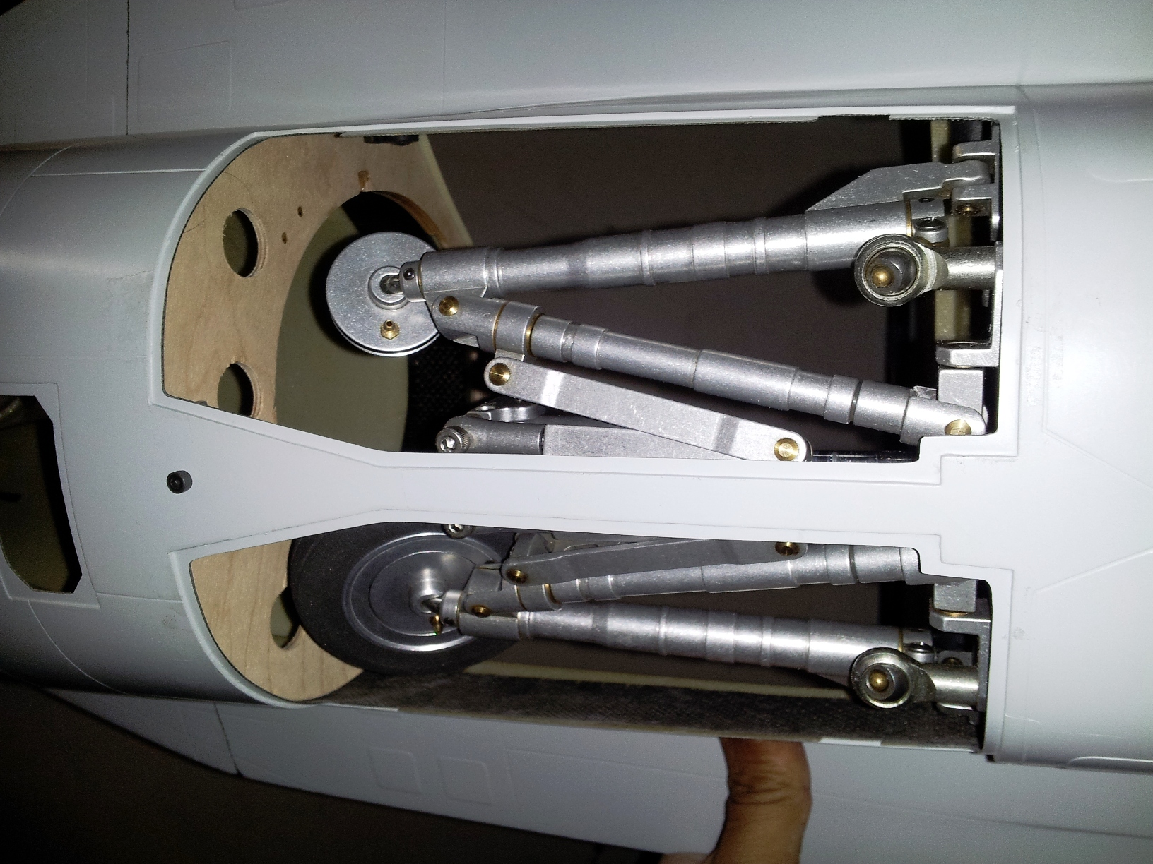
Those landing gear look like a work of art!
Those landing gear look like a work of art!
12-21-2013, 07:43 AM
#58
Thread Starter
Hi,
No the modification (which now seems unnecessary) would have been to the duct--not the inlet. The duct I mean is the one just aft of the fan unit. In the stock ducting, the duct and the exhaust tube are two separate pieces. In your plane, there'll be one long mylar tube instead of a two-piece fiberglass duct.
No the modification (which now seems unnecessary) would have been to the duct--not the inlet. The duct I mean is the one just aft of the fan unit. In the stock ducting, the duct and the exhaust tube are two separate pieces. In your plane, there'll be one long mylar tube instead of a two-piece fiberglass duct.
12-24-2013, 08:03 AM
#59
Thread Starter
Hi,
Work is progressing along nicely. Unfortunately, the BV inlet isn't going to work after all--at least not without cutting it up and adding some blisters to accommodate some stuff inside. That whole 'two objects occupying the same space at the same time' thing. The stock inlet has a ramp/blister for the nose-gear and a few sharp turns that the BV one doesn't (to conform to the interior of the fuse), so it's not as smooth. That being said, though, I doubt there will be much practical difference in flight based on what I've seen in real-world examples. Before I ever built an EDF powered version of this plane, I heard all of the scholarly explanations about how the stock inlet was unusable and could never feed the fan and blah blah blah. Finally, one builder who was experienced with the model messaged me and advised that I simply make sure not to tell the inlet any of this information and it would, in its ignorance, just fly the plane fine. That's pretty much what happened! Oh well, it would have been neat to have that neato inlet in there.
On this plane, the wing spars are solid carbon rods (6mm and 8mm) which are epoxied into hard balsa blocks. Those blocks are carved to shape (to conform to the airfoil curves) then epoxied into pre-cut slots in the foam core. Before any of this, though, you have to install the spar receiver clamps onto the formers. Once all that's done, you use the wings to locate the formers. I put the spars in the clamps, then slid the wings onto the spars/blocks and taped the wings into place. With the wings and the main gear holding the formers in position, I tack-glued the formers into position, then removed the wings and came back with hysol to permanently glue all the wood to the inside of the fuse.
The tail is basically done the same way. There are titanium stab shafts that are glued into hard balsa blocks. There is a counter-rotation pin that gets recessed into the root end of the block and subsequently glued to the root facing, too. The flat-spots for the stab set screws were not long enough, so I elongated them with a dremel. Fun to see the violet sparks when you grind titanium!
12-24-2013, 08:09 AM
#60
Thread Starter
Hi,
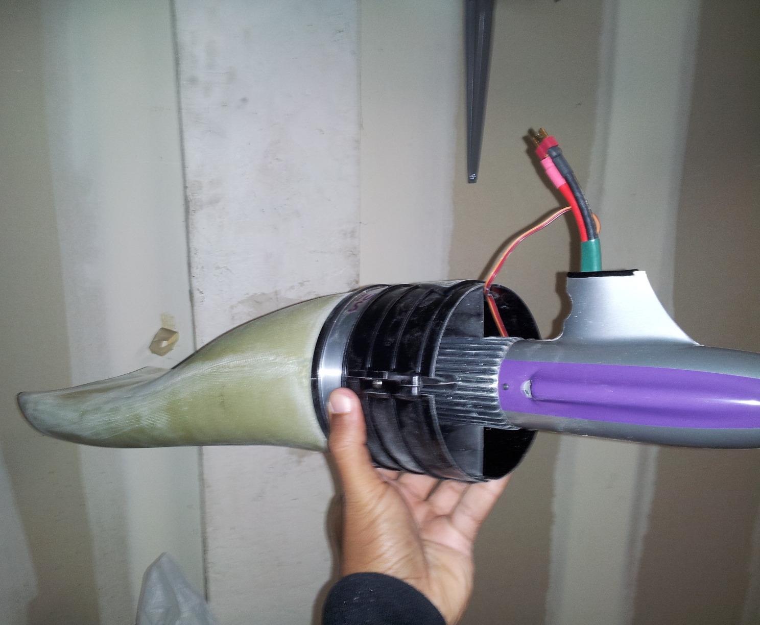
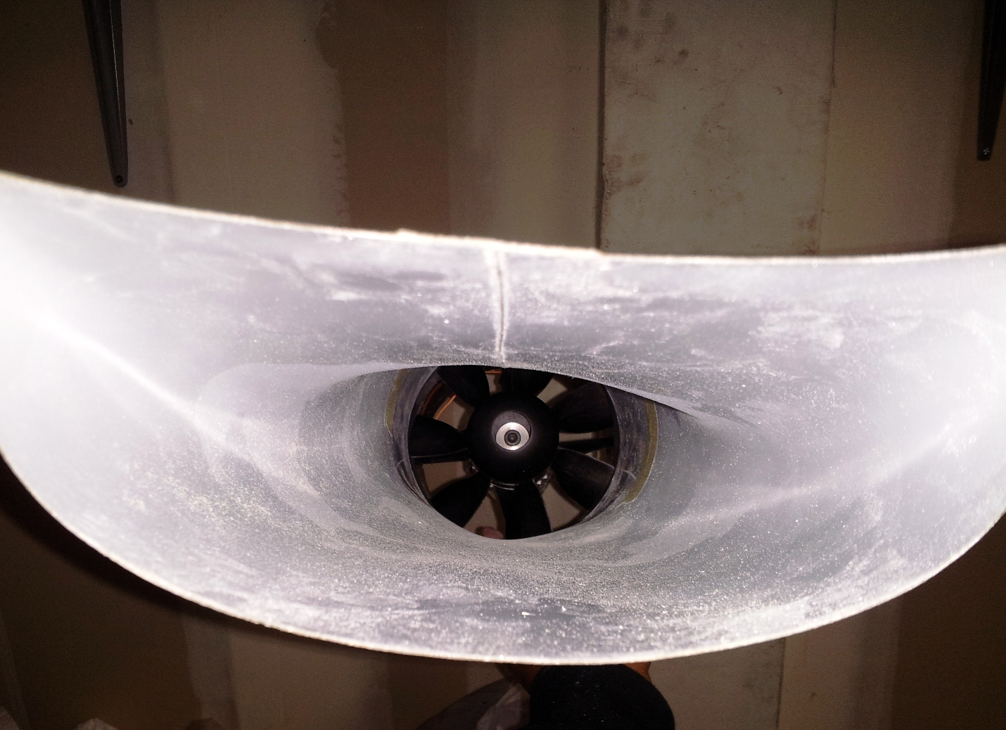
In these pics, you can see the gap between the inlet and the fan. I need to figure out the best way to neck that down to the fan with the least turbulence. There's a 4-5mm gap all around. Ideally, I'd like to slide the fan back about 2.5" so my adapter needs to be somewhat conical.
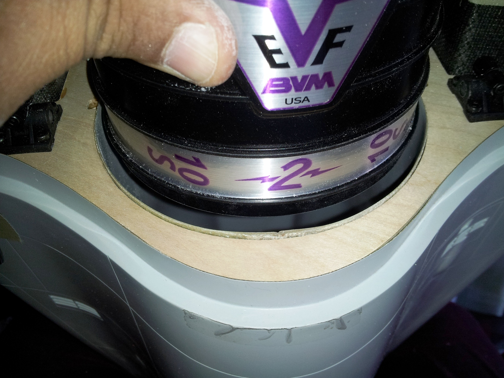
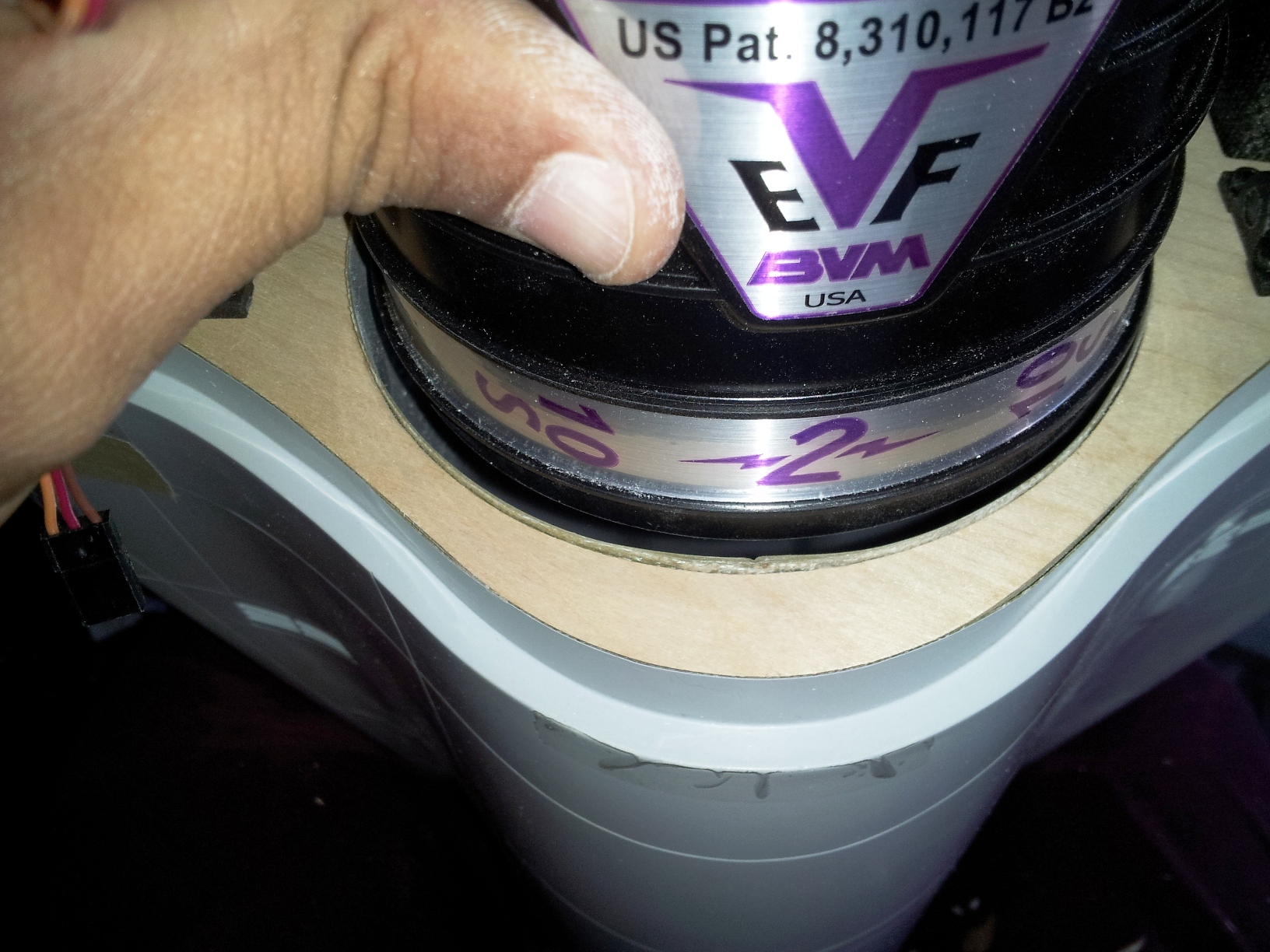
In these pics, you can see the gap between the inlet and the fan. I need to figure out the best way to neck that down to the fan with the least turbulence. There's a 4-5mm gap all around. Ideally, I'd like to slide the fan back about 2.5" so my adapter needs to be somewhat conical.
12-24-2013, 10:22 AM
#63

My Feedback: (12)
Join Date: Jul 2002
Location: Alexandria,
VA
Posts: 706
Likes: 0
Received 0 Likes
on
0 Posts
How big do the bumps need to be in the inlet? Of they aren't too big just use a heat gun to soften the resin and push it in with a big spoon or something of the appropriate size to get your bump.
12-24-2013, 11:54 AM
#64
Thread Starter
Hi,
Yeah, we're not talking little bumps here and there. If you look at the pic of the jet sitting on its wheels, you can see the bumps that the stock inlet needs to clear the nose gear stuff. Between the bumps and the curvature needed, I'd pretty much have had to turn the BV inlet into basically the same thing as the stock one.
Yeah, we're not talking little bumps here and there. If you look at the pic of the jet sitting on its wheels, you can see the bumps that the stock inlet needs to clear the nose gear stuff. Between the bumps and the curvature needed, I'd pretty much have had to turn the BV inlet into basically the same thing as the stock one.
12-24-2013, 12:57 PM
#65

Shaun BVM sells an inlet extension for their fans that has a funnel shape to it that I used on my YAF16 when I flew it with the EVF. They make it big so you can trim it down hover you want. I fit it inside the stock yellow duct buy tipping the plane on its nose and pouring some epoxy around it kind of the same way you install the inlet into the fuselage .It worked great and also moves the fan back to help with CG. If the batteries are going over the inlet in the nose you will need the fan installed further back for CG.
12-24-2013, 04:19 PM
#66
Thread Starter
Hi,
Yeah, I saw those back in the DF days. Already noted the fan position/CG consideration since I was using receiver packs located at the tail-cone last time. Good tip. Do you still have any video of yours flying on EVF? Which EVF unit did you use?
Yeah, I saw those back in the DF days. Already noted the fan position/CG consideration since I was using receiver packs located at the tail-cone last time. Good tip. Do you still have any video of yours flying on EVF? Which EVF unit did you use?
12-24-2013, 07:29 PM
#67
I don't have any video anymore. It flew well was just heavy with the bigger 6500 packs I had. Was around 18 lbs and that's just to much for this plane on landing. But I also had the wrong CG back then. I had the EVF 5612. If I was doing another one it would be turbine just for the fact of getting the batteries in and out is a pain.
12-24-2013, 07:48 PM
#68
Join Date: Nov 2013
Location: Fair Oaks, CA
Posts: 144
Likes: 0
Received 0 Likes
on
0 Posts
Gunradd, do you know the difference between the EVF 5612 and their EVF 2 & 3? Is the 2 &3 just newer fan designs?
The advertised weight of the EVF 2 that Shaun is installing is 2lbs 3oz with ESC installed. I don't think Shaun has weighed it to double check advertised weight vs actual. I would think that the weight should be fairly close to a Stumax 110 fan that is 1.5lbs w/o ESC. I am also planning on running 2 Revolectrix 5s 5000mAh 60c batteries as long as they fit.
I'm hoping it's going to be in the 15lbs range.
12-24-2013, 09:44 PM
#69
Thread Starter
Hi,
I'd be surprised if it's that light RTF. The good news is that the one in my videos is at 16.5 pounds and lands nice and light. The trick is to not try to fly it like a foamie or a trainer. It's a jet. As long as you treat it like one, she's a kitty cat!
I'd be surprised if it's that light RTF. The good news is that the one in my videos is at 16.5 pounds and lands nice and light. The trick is to not try to fly it like a foamie or a trainer. It's a jet. As long as you treat it like one, she's a kitty cat!
12-25-2013, 03:06 PM
#70
Thread Starter
Hi
Got into the shop for a couple of hours after opening presents and all. The stabs are pre-sheeted, but the leading edge balsa stick has to be epoxied on and sanded to shape. I got that done for both stabs, then capped the balsa rudder and sanded it to shape. I'm super particular about leading-edge radiuses and such. They have to be perfectly round (not bullet-shaped) and the radius has to be a perfect semi-circle relative to the thickness change in the surface--so the tip of the rudder is round and the thicker root is round, too.


Got into the shop for a couple of hours after opening presents and all. The stabs are pre-sheeted, but the leading edge balsa stick has to be epoxied on and sanded to shape. I got that done for both stabs, then capped the balsa rudder and sanded it to shape. I'm super particular about leading-edge radiuses and such. They have to be perfectly round (not bullet-shaped) and the radius has to be a perfect semi-circle relative to the thickness change in the surface--so the tip of the rudder is round and the thicker root is round, too.
 12-26-2013, 08:29 AM
#73
Thread Starter
Ha! I totally thought of that, and it would have solved the problem for the nose-gear obstructions, but I would have had to recess the top of the inlet as well to clear the internal area where the 'aux inlets' are. In my final analysis, making the BV inlet work would have been tantamount to transforming it into the stock inlet except for the diameter of the back of it being correct. It occurred to me that if it was really going to work, someone would have done it before now...

Yesterday, I got the vertical fin spar installed. This consists of an 8mm carbon tube glued into a balsa block which is carved to fit inside the fin. The tube is clamped onto the stab/fin bulkhead, and it's pretty solid when it's done. I used V-poxy to glue it on.
Last night, I tackled one of the trickier steps in this build which is the rudder torque rod installation. This is one of the few areas where the design is less-than-ideal in my opinion, although it obviously works as-is. Since the rudder hinge line is swept aft, the servo ideally ought to be up in the fin in order keep the linkage geometry at 90 degrees. In this case, that's not going to happen unless you want the servo itself in the fin which is ugly as hell if you ask me. This one uses a torque rod with the servo in the base of the dorsal. You end up with the linkage being closer to 120 degrees to the servo. I've seen even more severe angles still work, especially if you use good ball linkages, but I've never liked it so I modify it a little. First, I move the torque rod further down into the dorsal than is called out for. The rod assembly is an aluminum shaft with brass bushings and I glued one bushing at the very bottom of the rudder cutout, then make a wood brace to support another brass bushing at the lowest point the spar will allow the torque rod to rest. Then I use a servo that can squeeze into the inside of the fiberglass fin. Between bringing the torque rod arm down and the servo up, I've gotten the geometry darn close to 90.
12-26-2013, 04:16 PM
#75
Thread Starter
Hi,
The aileron end caps are a wee bit tedious, but also kind of a fun step. The wings are plug-in, and to do that without having any linkage showing, the flaperons are removed in order to install or remove the wings. The flaperon is held on by a small wire that slides through three hinges and some guide tubes. It's actuated by a torque rod that engages a sleeve in the fiberglass end-cap. It's somewhat tricky to set up, but once done, it's a trouble-free and clean way to have removable wings without any linkage showing.


The aileron end caps are a wee bit tedious, but also kind of a fun step. The wings are plug-in, and to do that without having any linkage showing, the flaperons are removed in order to install or remove the wings. The flaperon is held on by a small wire that slides through three hinges and some guide tubes. It's actuated by a torque rod that engages a sleeve in the fiberglass end-cap. It's somewhat tricky to set up, but once done, it's a trouble-free and clean way to have removable wings without any linkage showing.
Last edited by Shaun Evans; 12-26-2013 at 06:32 PM. Reason: Added pics