


BVM Plug and Play F16


 04-14-2021, 09:16 PM
#380
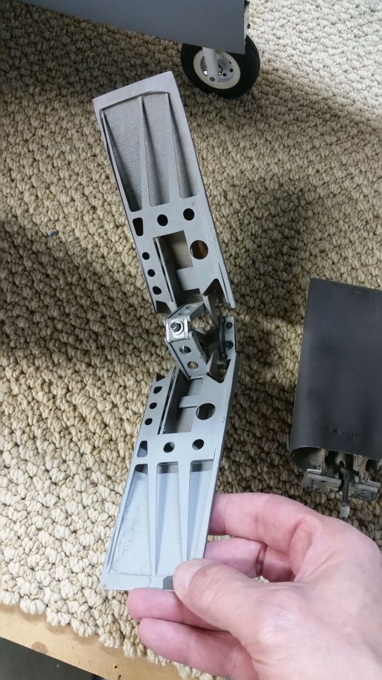
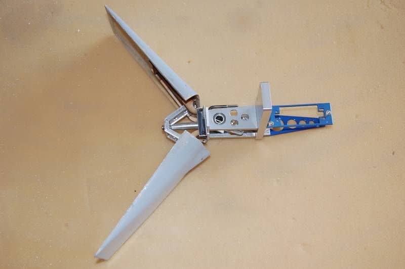
Well I got the BVM version of the 1/6th size F16 when I bought mine, so I'm not going to be able to help you. Considering the attach method for the 1/6th vertical stab on the 1/6th, making operational speed brakes would be a challenge as the above poster mentioned.
10-11-2021, 06:15 PM
#386
Oh, for what it's worth; mine is the PNP version.
Last edited by Zeeb; 10-11-2021 at 06:18 PM.
 10-12-2021, 05:56 PM
#389

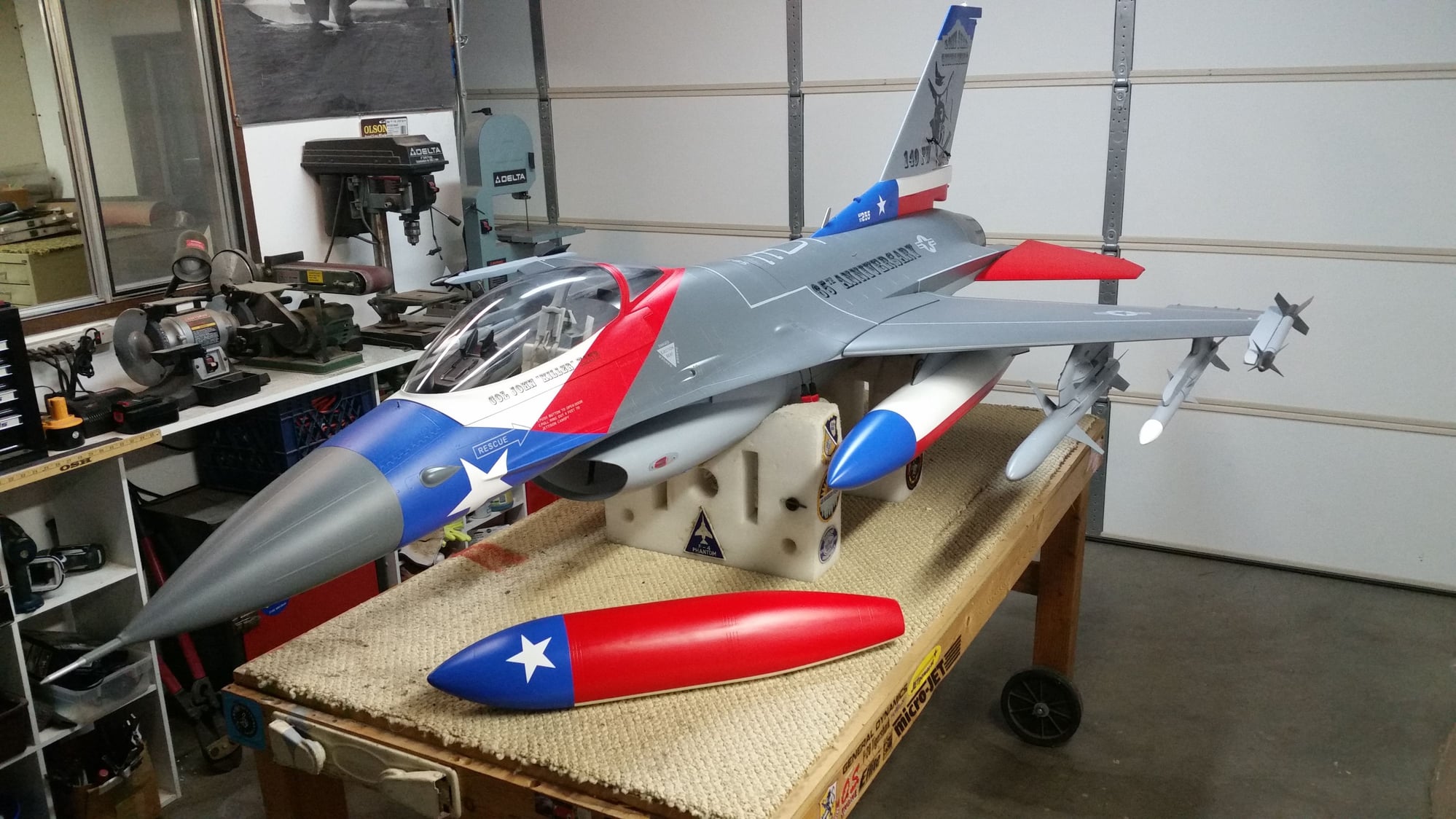
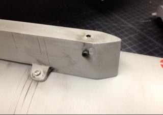
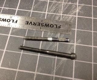
then i took a long 4-40 bolt and cut the head off and filed a flat on one end (like you would for a wheel axel). That then threads into the fuse with the end with the flat sticking out and to one side. My pylon has a set screw in the side that tightens against that flat. The tank stays mounted to the pylon.
So to install i thread the headless bolts in, then slide the tank/pylon assembly on and tighten the set screw in the pylon. Hope that make sense. The silver paint shows me when to stop screwing the headless bolt in.
Last edited by smchale; 10-12-2021 at 05:58 PM.
10-12-2021, 06:34 PM
#390
Thank you for sending the information!
Ok that would work but curious how you got up in the fuse or was it empty when you installed the inserts.
My holes are on the back sides of the formers that is impossible to reach with everything installed.
Ok that would work but curious how you got up in the fuse or was it empty when you installed the inserts.
My holes are on the back sides of the formers that is impossible to reach with everything installed.
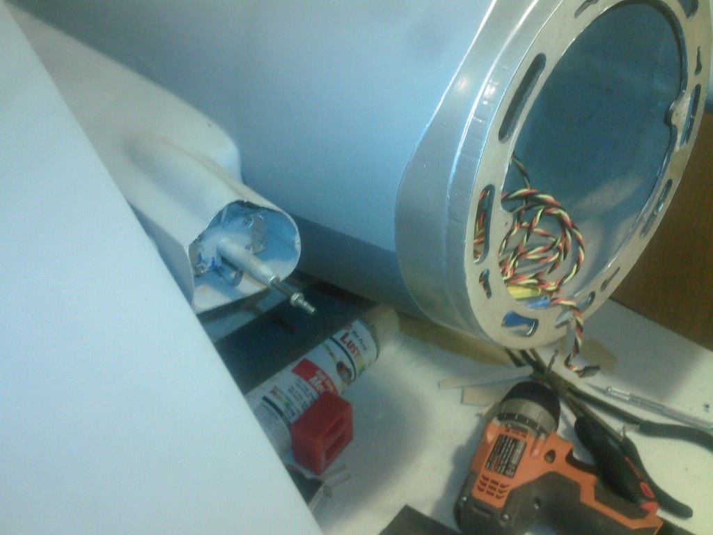
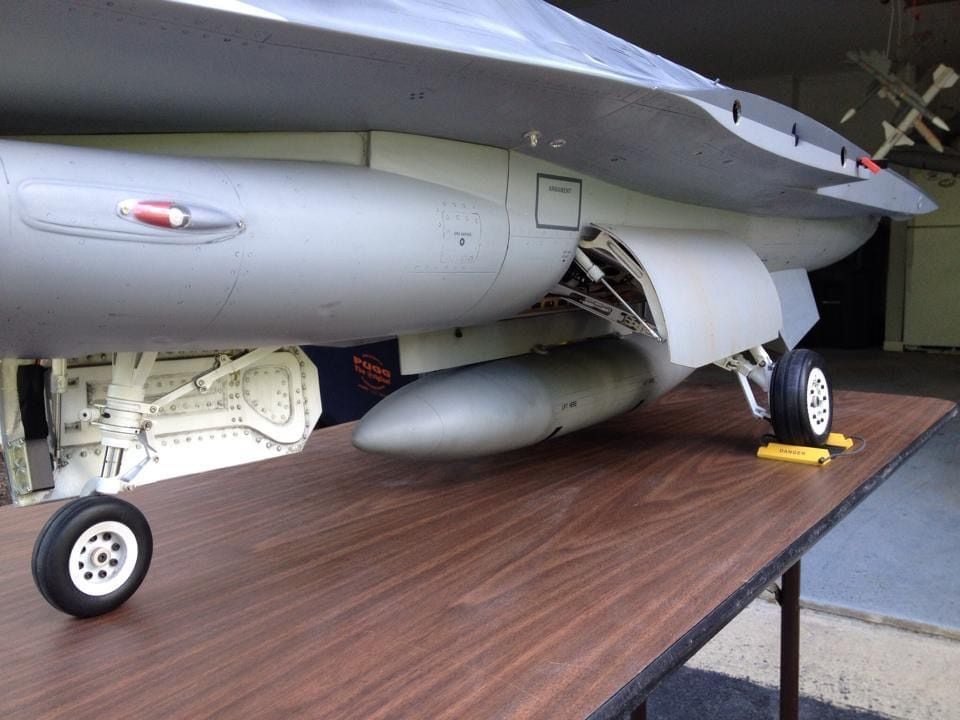
i mounted a pair of BVM 1� knurled threaded inserts into the bottom of the fuse.
then i took a long 4-40 bolt and cut the head off and filed a flat on one end (like you would for a wheel axel). That then threads into the fuse with the end with the flat sticking out and to one side. My pylon has a set screw in the side that tightens against that flat. The tank stays mounted to the pylon.
So to install i thread the headless bolts in, then slide the tank/pylon assembly on and tighten the set screw in the pylon. Hope that make sense. The silver paint shows me when to stop screwing the headless bolt in.
10-13-2021, 02:43 AM
#391
It was so long ago, but without the turbine in it’s accessible to both locations. One is right in front of the former that holds the back of the inlet ducting and the other is right behind the rear LG former. I used a long 3” 4-40 bolt in one end of the insert to guide it in position and then another screw in the bottom to hold it tight. The long screw also helped me make sure it was vertical before gluing. Then i added a bead of hysol around the knurled spacer. Once cured i could remove both bolts.
10-13-2021, 10:41 PM
#393
Yep, I have removed the turbine, helps on angle, but it's the stuff on the other side of the formers at the bottom of fuse and the fact the holes are right up against those formers. Pretty small holes so can enlarge them or move them.
I was thinking similar to Sean's method, and the way the wing tanks are done with tabs that hang, and the pylon is slotted to fit with a hole/screw on the side to secure.
I was thinking similar to Sean's method, and the way the wing tanks are done with tabs that hang, and the pylon is slotted to fit with a hole/screw on the side to secure.
10-13-2021, 10:46 PM
#394
It was so long ago, but without the turbine in it�s accessible to both locations. One is right in front of the former that holds the back of the inlet ducting and the other is right behind the rear LG former. I used a long 3� 4-40 bolt in one end of the insert to guide it in position and then another screw in the bottom to hold it tight. The long screw also helped me make sure it was vertical before gluing. Then i added a bead of hysol around the knurled spacer. Once cured i could remove both bolts.
