


T1 Models Euro Fighter build
 03-26-2018, 05:22 AM
#101


I finished up the wing servos by mounting the servo covers. One of the wings seemed to have a very thin skin at the leading edge of the cover, and the screw would not hold. I cut a slot and slipped a piece of wood in to give the screw something to bite to. A bit of trimming was needed so the cover would fit flush. I mounted the trailing edge covers using Zap Goo. They look nice, not sure they'll stay. That's what's nice about the Goo, I could take them off if needed with no damage. It took some work to make sure they moved smoothly with the surface.

Cover installed
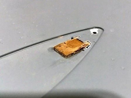
Added wood to give screw some bite
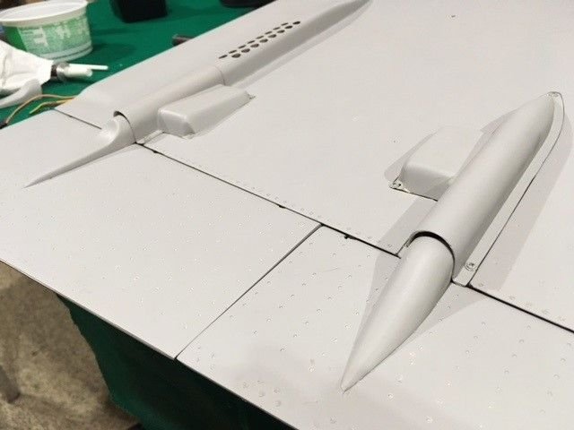
Trailing edge covers installed
Cover installed
Added wood to give screw some bite
Trailing edge covers installed
 03-26-2018, 05:29 AM
#102
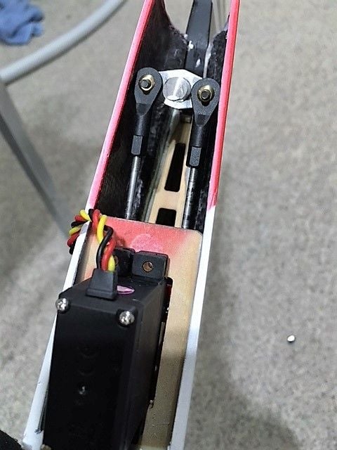
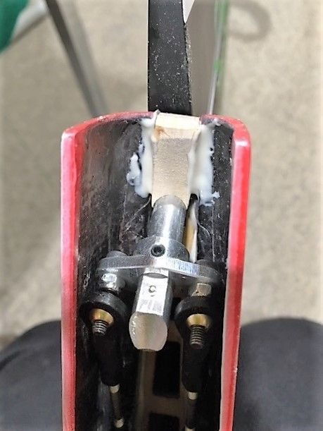
On to the Rudder servo. The horn provided is not very wide, so I was able to find a servo horn with the same width between the holes. I needed to mount it in a way that it's all removable even after the rudder is glued on. I used screws with lock nuts that provide studs handing down, then I can slide the ball links on and off even after the rudder is glued. I moved the horn on the rudder a bit farther up than the flats provided, made my own. I also only used the back set screw. That way I'll be able to take it off if needed. One screw can actually hold better than two anyway. I trimmed just a bit off of the rod hooked to the rudder so that it would not hit the fuse. Once I had everything lined up and working smoothly, I was confident to glue on the rudder. If needed, I can take it all apart. It's a nice system.
To add a bit of strength and take away some strain on the hinges I added a piece of wood as shown in the last photo.

To add a bit of strength and take away some strain on the hinges I added a piece of wood as shown in the last photo.
03-26-2018, 05:46 AM
#103
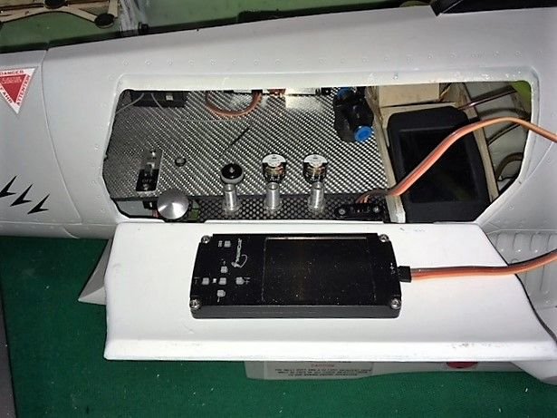
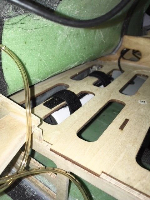
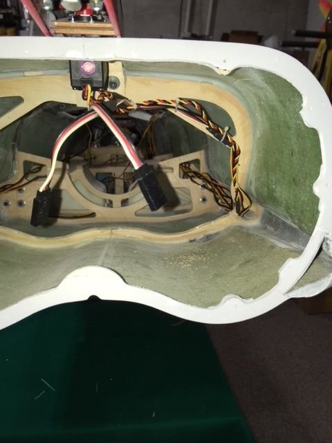
If you built a jet before, you know it's a challenge to get everything to fit. It's important to figure out where all the controls will be, and make everything accessible. The hatch on the side is the best place to access the controls, so I wanted most of the things I needed to get at located there. I added a piece of carbon fiber to move the air fill valves closer to the edge of the door. I also mounted a jack to plug in the Jet Central control panel. I could have bought a small one to carry on board, but I didn't need it. I'll put some velcro on the hatch and set it there during the start sequence, then unplug it and put it in my pocket before shutting the hatch. I also mounted the air gauges, as well as the receiver power switch and LED towards the front. I made a loop for the fuel fill that will be available there as well. The fuel shut-off valve will be easy to reach inside. Off to the right you'll see the display for the Booma RC battery system, the AR smart switch. This monitors everything on the two receiver batteries.
I mounted the bubble-free tank up in front as well. I made a bracket and used a Velcro strap to hold it in place. I like that I can look inside when the canopy is open and see how well it's filling, as well as make sure there is not much air in there after a flight. In the second photo you can also see where I plan to put the turbine control module and the receiver. There's room on the edge for all of the receiver connection wires to come up from the bottom. Underneath the panel shown I'll mount my main gear air valve. The other four air control valves (brakes, air brake, canopy up, canopy down) will all be in front. I'll show the locations for those soon.
Controls accessible through the hatch

Bubble free tank mount, and everything else
I mounted the bubble-free tank up in front as well. I made a bracket and used a Velcro strap to hold it in place. I like that I can look inside when the canopy is open and see how well it's filling, as well as make sure there is not much air in there after a flight. In the second photo you can also see where I plan to put the turbine control module and the receiver. There's room on the edge for all of the receiver connection wires to come up from the bottom. Underneath the panel shown I'll mount my main gear air valve. The other four air control valves (brakes, air brake, canopy up, canopy down) will all be in front. I'll show the locations for those soon.
Controls accessible through the hatch
Bubble free tank mount, and everything else
03-27-2018, 02:49 AM
#107

Join Date: Feb 2015
Posts: 208
Likes: 0
Received 0 Likes
on
0 Posts
Update this very minute as I posted,
My agent from just confirmed to me that he got hold of Kim, and informed he will be sending them directly tomorrow.
Thanks Jean-Marc. Seriously, if it was not for Kingtechturbines.lu this plane would never have made it.
sorry for the deviation on Hot Rod Todd's build.
My agent from just confirmed to me that he got hold of Kim, and informed he will be sending them directly tomorrow.
Thanks Jean-Marc. Seriously, if it was not for Kingtechturbines.lu this plane would never have made it.
sorry for the deviation on Hot Rod Todd's build.
03-27-2018, 11:03 AM
#108
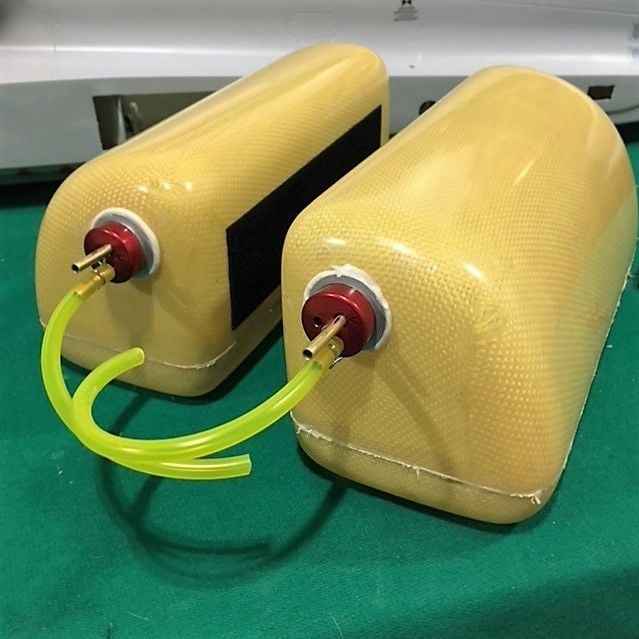
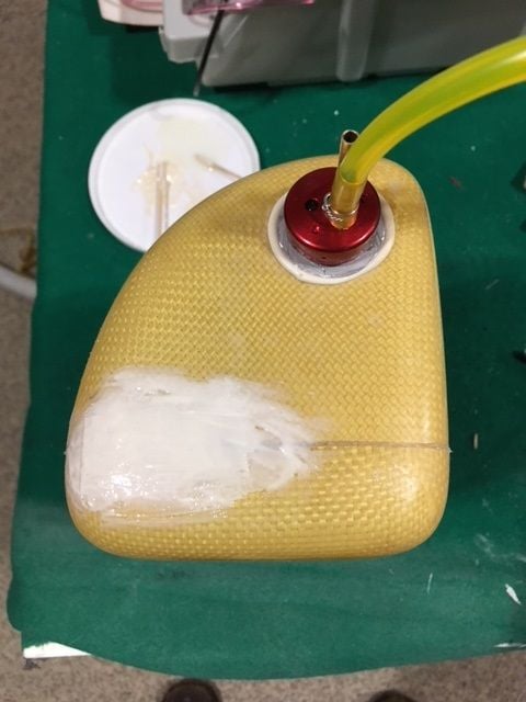
Got the plumbing installed in the fuel tanks. I used Hysol to glue the machined fuel tank inserts in place. Be aware these are not included in the kit, but it's something you need. You can get them from places like Dreamworks RC. I used Sullivan stoppers and typical tank hardware. Prior to installation I'll test them to make sure there are no leaks. I've seen pinhole leaks in Kevlar tanks before, and had to use some Hysol to patch them. These look good, so hopefully they'll be tight. I plan on using Velcro to hold the tanks together, Velcro at the base, and Velcro strap to hold them down. It will be one of the later things I do so I have room to run all the wire and tubing through the plane.
I made a mount for my UP3 main retract sequencer valve. It will be mounted under the main tray using Velcro. I like that I can move it to make it easier to hook up or make adjustments. That will be one of the first things I hook up. The only thing connecting to the main tray will be the source from the fill valve/gauges. Won't be long and I'll have everything in place, so I'll start the long process of routing plumbing, making servo extensions, and routing all the wiring.
Fuel tank with stoppers installed
Air valve mounted with Velcro
03-27-2018, 01:09 PM
#109

Dirk at Pacificrcjets sells threaded inserts along with a fuel vent you hysol to top of tank. That is the best option.
plumb tanks in series works great. The two main tanks are plenty of fuel for about 7 or 8 mins of hard flying with a 160.
good build so far hotrod
plumb tanks in series works great. The two main tanks are plenty of fuel for about 7 or 8 mins of hard flying with a 160.
good build so far hotrod
03-28-2018, 05:01 AM
#110
I plan to plumb the tanks in series as well. 7 or 8 minutes of flight time should be perfect. I used the stoppers I already had, but I agree that the screw type with the separate vent is a great way to go. Dirk should add that as an option, most people would buy it.
On with the build.
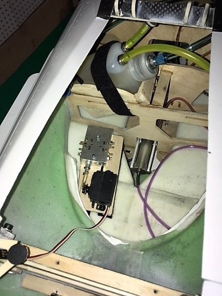
As mentioned, I'll be using two medium air tanks and one large (Robart). I decided to fit the medium tanks under the fuel tank mount, but have them off to the side so they don't interrupt the air-flow from the intakes. To get them in you have to have the gear down and come through the front. I used Velcro to mount them, as well as Velcro straps. One tank is for the wheel brakes and air brake, the other is for the canopy. The main gear tank is large, and mounting locations are limited. I found that it fits nicely along side the turbine. I will use some Zap Goo to hold it in place along with a block that slides in underneath. I'll mount it after I get the wiring and tubing routed from the back.
Next steps: Install the tail and get all wiring and tubing routed to the rear, install the Y-pipe, install the turbine.
Air tank for Canopy
Air tank for Brakes
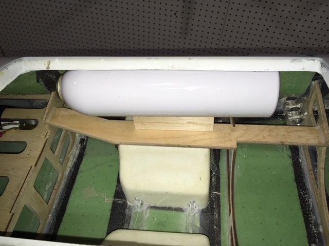
Main air tank
On with the build.
As mentioned, I'll be using two medium air tanks and one large (Robart). I decided to fit the medium tanks under the fuel tank mount, but have them off to the side so they don't interrupt the air-flow from the intakes. To get them in you have to have the gear down and come through the front. I used Velcro to mount them, as well as Velcro straps. One tank is for the wheel brakes and air brake, the other is for the canopy. The main gear tank is large, and mounting locations are limited. I found that it fits nicely along side the turbine. I will use some Zap Goo to hold it in place along with a block that slides in underneath. I'll mount it after I get the wiring and tubing routed from the back.
Next steps: Install the tail and get all wiring and tubing routed to the rear, install the Y-pipe, install the turbine.
Air tank for Canopy
Air tank for Brakes
Main air tank
03-29-2018, 05:23 AM
#111
I mounted the vertical stab so I could start routing the wires from the tail. I had to grind out the hole for the front bolt a bit, but in the end it matched up well. I was happy with how it mounted, it feels secure. I installed the Ashlock connectors that will hook up to the wing. These are secure connectors that minimize the connections you have to make when installing the wing. (Dreamworks RC sells them). You'll need a servo connection crimp tool to make your own. I ran the wires from the tail and secured them (as shown earlier in this post) to prevent them from touching the pipe.
Speaking of the Pipe, upon inspection I noticed some issues that make me afraid to use it. I contacted Dirk and he was quick to respond. Hopefully I'll get it resolved, because it could delay my build progress. I can install the pipe from the back, so it doesn't stop me from moving on with other steps. I'll have to hold off installing the turbine though. The pipe location basically sets the turbine location.
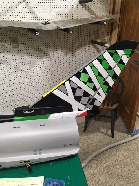
Vertical Stab installed
Ashlock connector
Tail wire routing
Speaking of the Pipe, upon inspection I noticed some issues that make me afraid to use it. I contacted Dirk and he was quick to respond. Hopefully I'll get it resolved, because it could delay my build progress. I can install the pipe from the back, so it doesn't stop me from moving on with other steps. I'll have to hold off installing the turbine though. The pipe location basically sets the turbine location.
Vertical Stab installed
Ashlock connector
Tail wire routing
03-29-2018, 07:04 AM
#112
My Feedback: (1)
Hot Rod Todd,
Really nice looking build. Where you have your air bottle is where I ended up having to put my ECU battery to get it to balance out( you probably have room on the other side if needed) so I placed the air tank horizontal in bottom of jet up against that bulkhead in your photo. I'm sure you have already thought of this but with those afterburner rings already installed , the pipe has to be put inside the fuse and pulled all the way forward, then attach your tail nozzle /afterburner ring assembly to the back of the fuse ( only way to see to put screws in), then the pipe tips have to be guided thru the plywood former and slide thru and out the nozzles. I just remember finding it a bit tricky and glad I didn't have to repeat it..LOL
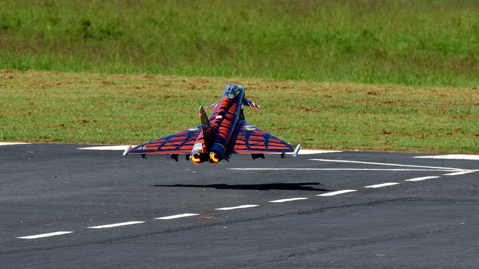
Really like the invasion stripes scheme..... very easy to see. This was mine (pre T one) ( as a test flight before I painted). It was a CARF. The T one is a much more scale version. Someday I hope to get it back together and actually get to fly it.
Marc


Really nice looking build. Where you have your air bottle is where I ended up having to put my ECU battery to get it to balance out( you probably have room on the other side if needed) so I placed the air tank horizontal in bottom of jet up against that bulkhead in your photo. I'm sure you have already thought of this but with those afterburner rings already installed , the pipe has to be put inside the fuse and pulled all the way forward, then attach your tail nozzle /afterburner ring assembly to the back of the fuse ( only way to see to put screws in), then the pipe tips have to be guided thru the plywood former and slide thru and out the nozzles. I just remember finding it a bit tricky and glad I didn't have to repeat it..LOL
Really like the invasion stripes scheme..... very easy to see. This was mine (pre T one) ( as a test flight before I painted). It was a CARF. The T one is a much more scale version. Someday I hope to get it back together and actually get to fly it.
Marc
03-29-2018, 07:33 AM
#113
Now that you mention it I see what you're talking about with the tail piece screws. The pipe sits tight around the rings, leaving no space to put the screws in. I might be able to deform the bell on the front just enough to slide the pipe forward through the afterburner rings to access the screws, then slide it back into place. I say slide it, but it's difficult to move that pipe in with the sharp edges always catching. If I find a procedure that works you can be sure I'll post it.
Doing some test fitting my turbine will be pretty far back on the mounting rails to get me about 1" between the end of the outlet and the start of the narrow part of the pipe. If I have to move a battery back, that would be better than putting nose weight in it. My Cheetah 160 turbine is not as heavy as some others (8 oz. less than a JetCat or Kingtech 160) so I still may have to move some weight back.
Doing some test fitting my turbine will be pretty far back on the mounting rails to get me about 1" between the end of the outlet and the start of the narrow part of the pipe. If I have to move a battery back, that would be better than putting nose weight in it. My Cheetah 160 turbine is not as heavy as some others (8 oz. less than a JetCat or Kingtech 160) so I still may have to move some weight back.
03-29-2018, 07:56 AM
#114
My Feedback: (1)
Yeah, you are correct, it will be tight to move forward enough but it can be done. My suggestion would be to find a couple of thinnest sheet plastics you can, roll them in a tube , insert thru the opening of the tail nozzles. Let them expand inside enough to easily start sliding your pipe thru( using them like guides) , once pipe tips clear the wood former opening , then pull out the plastic. I think Im gonna try that when I start to put mine back together. Those sharp edges of pipe outer shell grab on anything and you don't want to booger them up!
Good luck.
Marc
Good luck.
Marc
03-29-2018, 09:32 PM
#115
Join Date: Feb 2015
Posts: 208
Likes: 0
Received 0 Likes
on
0 Posts
Great pointers to ensure good CG. I will try and make my Powerpack and battery pack sit on the side of the engine, and install the UAT as far back as feasably possible.
Haven't started my build yet. Flying season started slowly, so am spending my time at the field.
Thank you for all the lovely installation and build pictures.
The main reason I went for the invasion scheme was visibility. The Bavarian is way more wicked!
Rather then ashlock connectors, I was planning on the emcotec wing plugs. They do need soldering though, but used them on other occasions and they held up excellently on my gassers
Thanks Guys!
G
03-30-2018, 04:58 AM
#116
I thought I'd check my fuel tanks for leaks before installing them. My stoppers were tight with no leaks, but I did find a pinhole leak in one of the tank seams. I sanded it a bit and used some Hysol with a piece of glass to patch it up. Should hold up just fine. I'm busy routing wires and tubing. Before I got everything too locked into place I'm in the process of testing the retract system.
Hysol used to seal tank
Hysol used to seal tank
 04-02-2018, 05:45 AM
#118
Didn't make a lot of progress this weekend, but I got a lot done. When I tested the Retracts I was having some issues, so I had to dive in and resolve everything. Here are some things I noticed that you should check out.
The set screws have nice flats on the shafts, but not all of them have Loctite or are even tight. Don't forget to Loctite and tighten them all (standard practice).
If you use the mounting screws provided with no washers, they are a bit long. Be careful you don't tighten them up and damage the surface of the wing. I shortened mine.
The retracts may hit on the fuse when you slide on the wing, make sure you check for clearance and grind away what's needed.
One of the pistons hit the wing skin when the gear was cycled causing some binding. A little bit of grinding on the corner of the piston, and a bit on the inside of the skin (being careful not to go through) fixed it.
The air cylinders come apart, but the caps were not tight as delivered. That's fine, because as you'll see on the next comment I had to take them apart.
Most important: When cycling there were times when the gear would hang up and air would leak past the cylinders. It wasn't all the time, but enough to worry me.
Upon investigation it appears the groves in the piston are a bit deep for the o-ring provided. A trip to the hardware store and I found slightly bigger o-rings that solved the issue. The quality of the pistons and the way they come apart was excellent. Now that I have the correct O-rings I'm confident that the gear will be reliable.
04-02-2018, 06:00 AM
#119
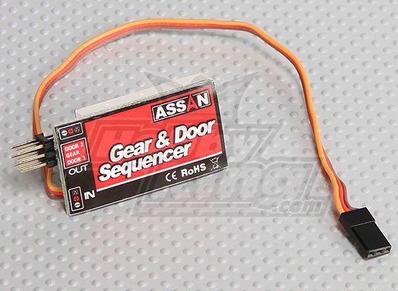
I'm setting up the operational canopy using servo's and valves. I mounted them up underneath the cockpit. As long as you keep everything flat they'll fit. I was going to just make it manual operation to save the channels, then I decided it's just too cool to open it with the radio. To allow me to only use ONE channel, I decided to use an inexpensive sequencer from Hobby King. It allows you to set all of the throws, and delays. I haven't mounted the canopy yet to test it, but I should be able to get the timing right to make it work.
I'm using one of the rotary knobs. Since I have to rotate the knob a half turn to actuate the canopy, there should be less chance that I would hit a switch in error that caused the canopy to open in flight with obvious results. To actuate the sequencer, you have to cycle it three times quickly. Once that initiation is done, it will cycle when you hit the switch (twist the knob in my case). Don't forget to download the manual if you buy one, that's the only way you have a chance of setting it up. It's about $15. See the photo below.
By the way, while you're ordering from Hobby King they have a wing bag that will work (1100mm version). I had to modify it a bit because of the wing tip pylon, the tip of the pylon sticks out through a hole. Two wings fit, but it's really tight. I think I'll use two bags, put one wing in each. At only $27 each they are quite nice (looks like $29 now). I can hear it already. "That's a nice looking jet for something from Hobby King"
04-04-2018, 06:03 AM
#120
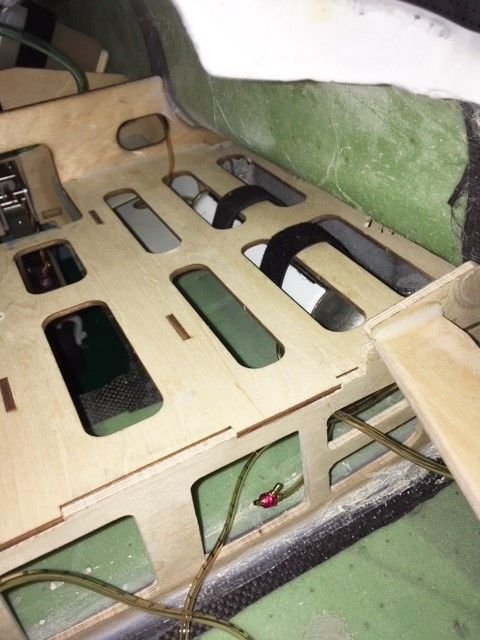
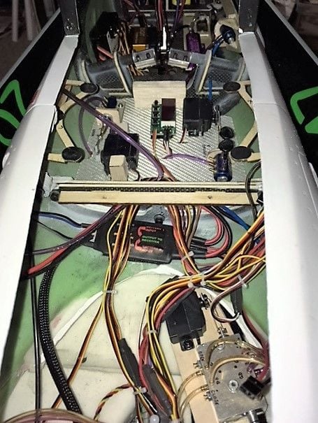
Getting all of the wiring and tubing installed is a bit of work. I think I have everything located in a way that will work out. All of the canopy air controls are located up under the cockpit. I was able to run the wires from the front underneath that front shelf, but it's tight. Organizing the main area behind the magnetic hatch now. Once I put that shelf in it should look pretty clean. Just don't peak under the hood! I didn't have much luck with the electronic switch I wanted to use to kill the landing lights when the retracts go up, so I went old school and used a micro-switch that is actuated by the main air valve. It worked out well. Here are some in-progress photos showing where I put everything.
Initial CG checks made me think that I was fairly close on nose weight. I'm close enough to completion that I think I'll throw everything in and see what I have. If I have to move a battery back it's a bit of work, but better than adding lead to the nose. I'll be curious to do an all-up weight check as well.
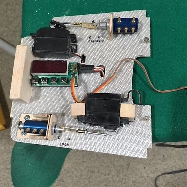
Canopy air controls

Initial CG checks made me think that I was fairly close on nose weight. I'm close enough to completion that I think I'll throw everything in and see what I have. If I have to move a battery back it's a bit of work, but better than adding lead to the nose. I'll be curious to do an all-up weight check as well.
Canopy air controls
04-06-2018, 05:45 AM
#122
So far the door actuators seem to be holding air fine, but I've done minimal testing. I still have to get the canopy hooked up to see how those air cylinders work as well.
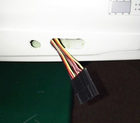
Spending more time routing and organizing the cables and tubing. To prepare for the fuel system I had to determine where to put the vent fitting. I like to be able to reach it with my overflow tank sitting on the wing. It's also good if it exits out the bottom so it doesn't spray fuel on the side of the plane. I decided to put it down right in front of the left intake. I added some reinforcement in the form of a piece of glass. See the photos for the install.
Some investigation of the canopy prior to installation revealed that they say to use some self tapping screws to hold it on. That's not good for me, screwing into some thin glass material. I mounted a piece of ply to the mount with some 4-40 blind nuts in it. I also added a piece of wood to help strengthen the canopy hinge. I used some of my own hardware with ny-lock nuts to hold it together. It moves smoothly without a lot of friction. I should be getting the canopy mounted in the next couple days.

Vent fitting inside fuse
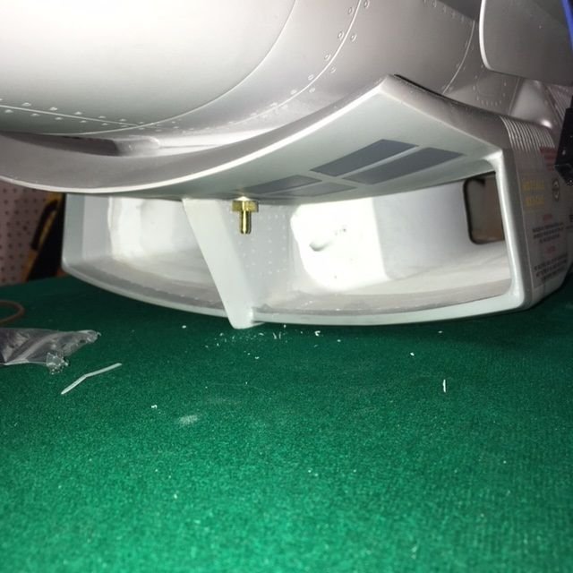
Fuel vent fitting location outside
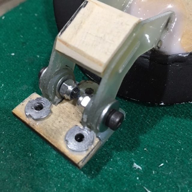
Modified canopy hinge
Spending more time routing and organizing the cables and tubing. To prepare for the fuel system I had to determine where to put the vent fitting. I like to be able to reach it with my overflow tank sitting on the wing. It's also good if it exits out the bottom so it doesn't spray fuel on the side of the plane. I decided to put it down right in front of the left intake. I added some reinforcement in the form of a piece of glass. See the photos for the install.
Some investigation of the canopy prior to installation revealed that they say to use some self tapping screws to hold it on. That's not good for me, screwing into some thin glass material. I mounted a piece of ply to the mount with some 4-40 blind nuts in it. I also added a piece of wood to help strengthen the canopy hinge. I used some of my own hardware with ny-lock nuts to hold it together. It moves smoothly without a lot of friction. I should be getting the canopy mounted in the next couple days.
Vent fitting inside fuse
Fuel vent fitting location outside
Modified canopy hinge
04-09-2018, 05:02 AM
#123
Got some more work done on the canopy and the air system that operates it. Even with the strengthened hinge, the canopy could still drop down cocked enough that the locking pins would not engage. I decided to make some guides to help bring it down into place better. I added a little ply to the edge of the canopy where it would hit the guides. Guides are ply glued to the side of the opening with Hysol. Testing showed that it slammed down and up a bit, so I put a Robart air restrictors in both the up and down lines. This worked well, and the canopy moves up and down smoothly and locks into place every time. I didn't need much delay in my sequencer to get it to work. The four cockpit air cylinders all hold air well. I'm happy with the canopy operation.

Canopy Guides in place
Canopy Guides in place
04-09-2018, 05:07 AM
#124
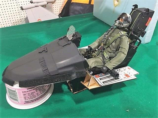
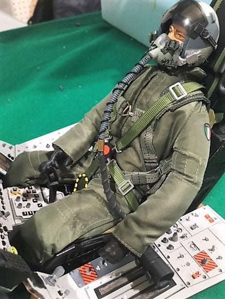
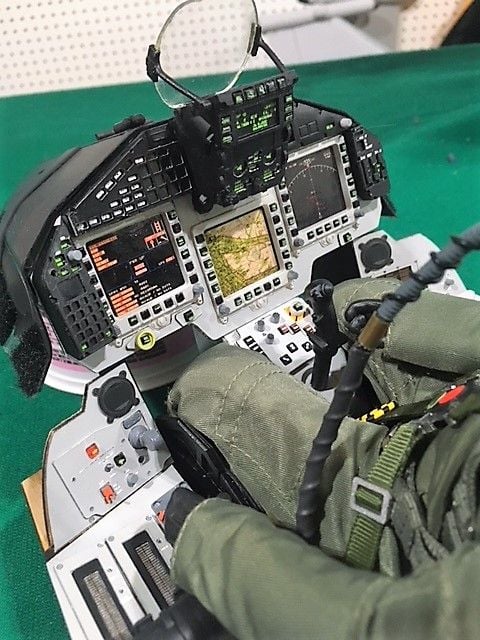
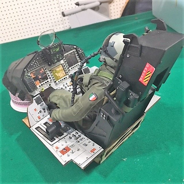
While the glue was drying on the canopy guides I did a bit of work on my Cockpit. I added some scale detail on the dash cover (area right under the front canopy). The seat belts went on nicely and I added an extension to the oxygen mask. A few other minor details and I'm happy with how it turned out. I usually have to build a cockpit with little help, so despite the cost it was nice to have a good looking starting point. It's slightly tall, so I will re-mount the two things that stick up from the top of the ejector seat to make sure they don't touch the top of the canopy when it closes.
04-09-2018, 05:11 AM
#125
I finally got everything in place and can do some testing. I made a cable that goes on the magnetic access door. I plan on setting my turbine display onto the door when starting, and I didn't want to stress out the hinges over time. In the photo you can see the door as well as the way my controls are accessible. Everything is under that door, except for the charging jacks that are under the nose cone.


