Mibo A-10 Gen 6


 11-13-2020, 07:28 AM
#510

You are welcome Jim!!
I got 2 more flights on the hog yesterday. I got some video and will need to edit and then I’ll post some!
Jack Diaz Sr gave me a very good tip on mixing some down elevator (15%) with less than 1/2 throttle. Coupled with the demon cortex, these two flights felt like a whole new airplane!!
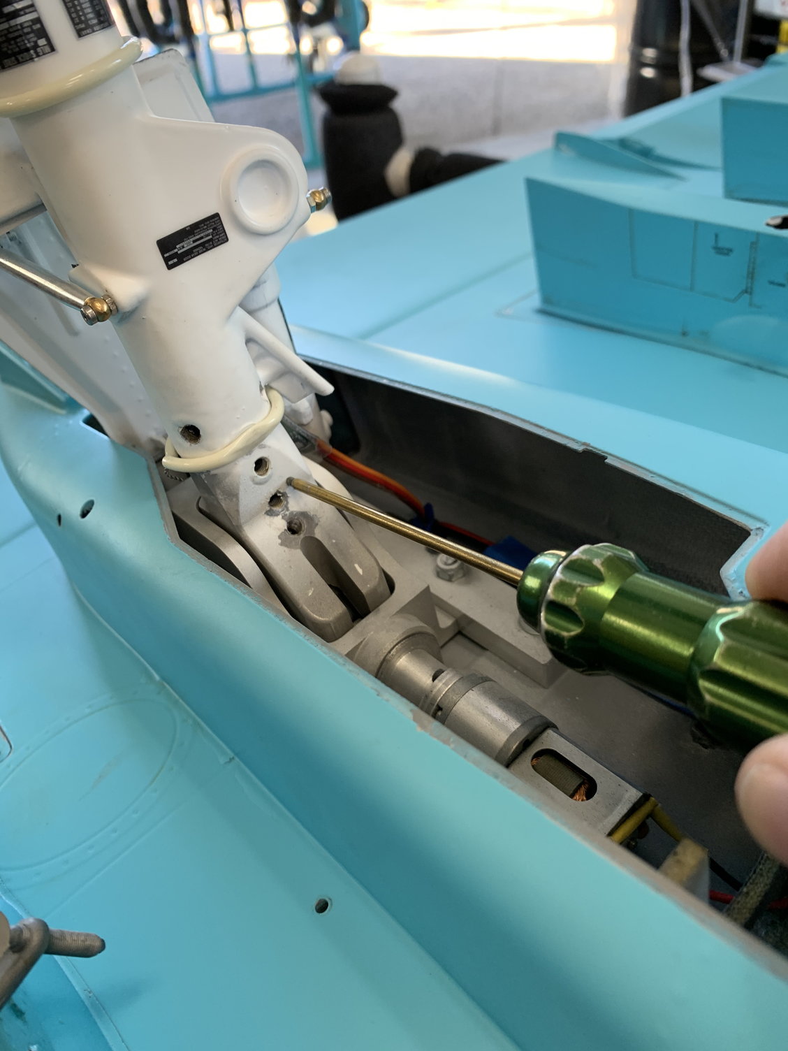
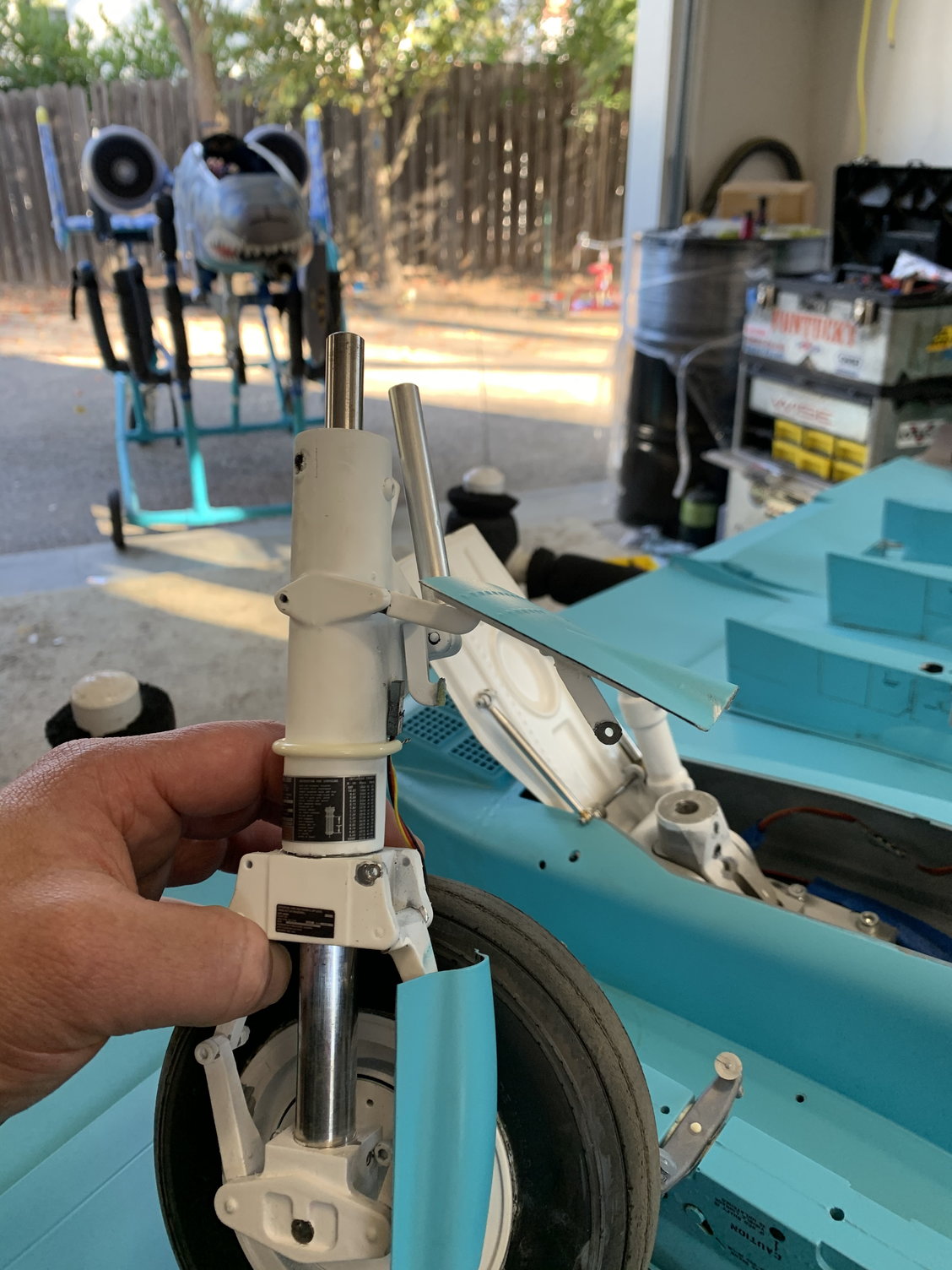
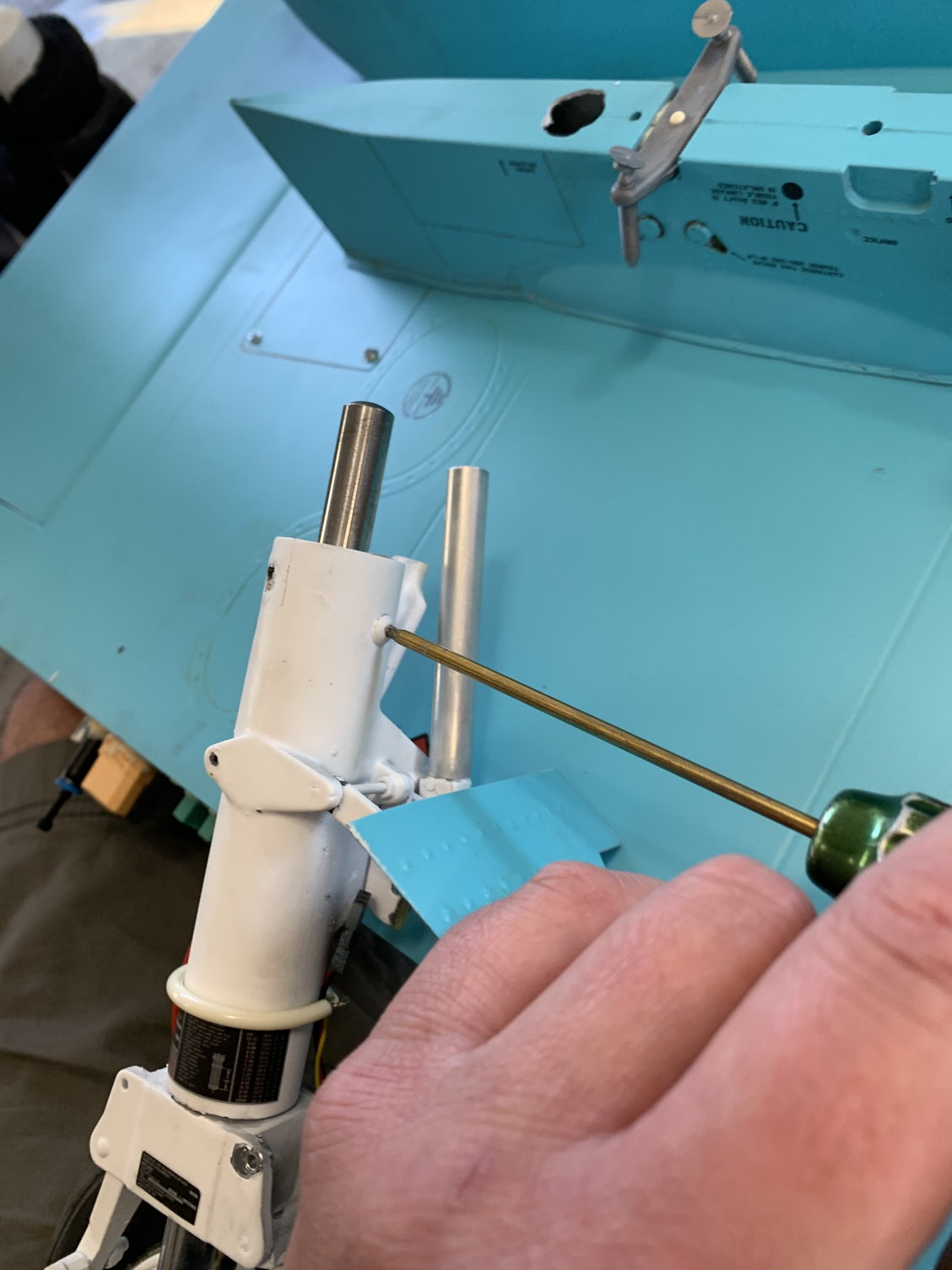
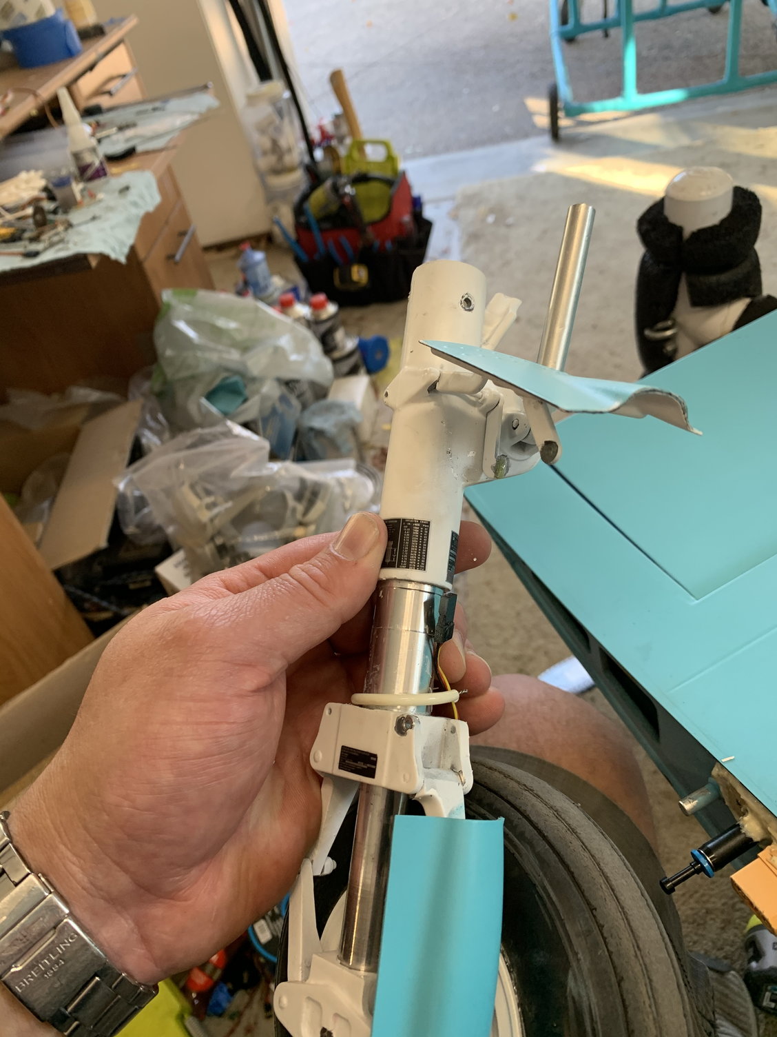
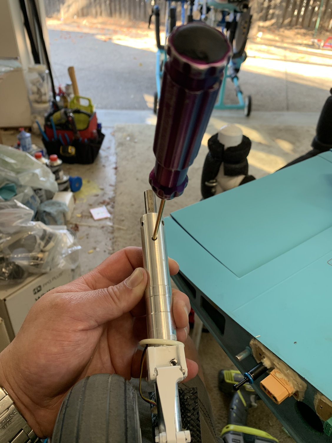
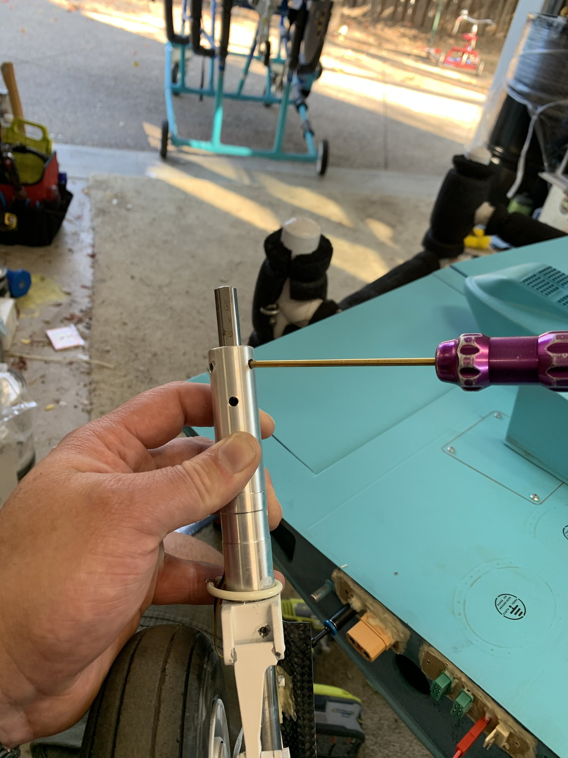
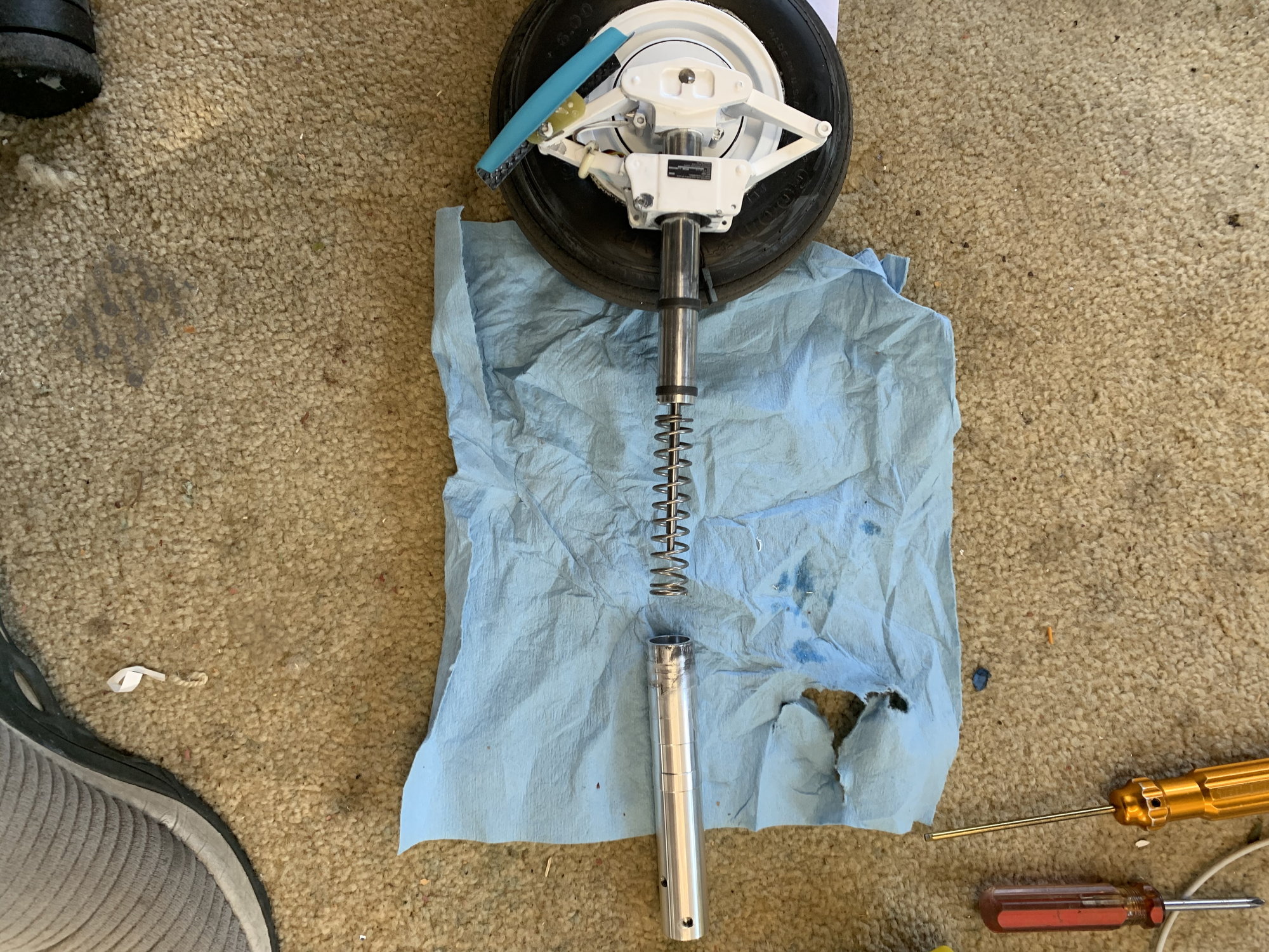
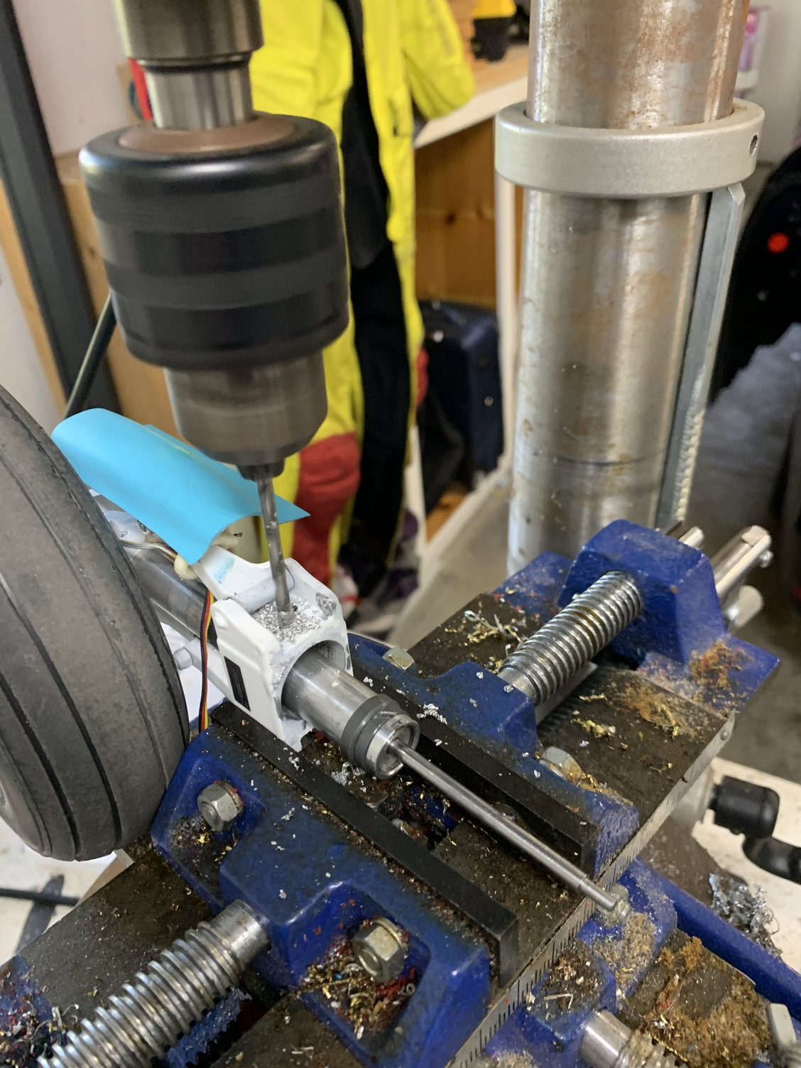
The gear fix I did seemed to work. I had to retighten one set screw on one side. The plastic covers over the struts can rub some of the loctite off.
11-13-2020, 07:40 AM
#511

My Feedback: (6)
You are welcome Jim!!
I got 2 more flights on the hog yesterday. I got some video and will need to edit and then I�ll post some!
Jack Diaz Sr gave me a very good tip on mixing some down elevator (15%) with less than 1/2 throttle. Coupled with the demon cortex, these two flights felt like a whole new airplane!!
The gear fix I did seemed to work. I had to retighten one set screw on one side. The plastic covers over the struts can rub some of the loctite off.
Thx
11-13-2020, 09:34 AM
#513
My Feedback: (6)
Ok
IMHO
That means that the CG is rwd and the thrust is pushing it down ( that also could be due to the high positioning of the turbines relative to the aircraft thrust line inducing a pitch down force at high throttle setting )
solution other than mixing : proper CG location .
Second : rectify the thrust line angle on the turbine exhaust via a vector ring . If I recall the turbine exhaust on the full size are facing up some for the same reason I believe ..
11-13-2020, 10:36 AM
#514

Ok
IMHO
That means that the CG is rwd and the thrust is pushing it down ( that also could be due to the high positioning of the turbines relative to the aircraft thrust line inducing a pitch down force at high throttle setting )
solution other than mixing : proper CG location .
Second : rectify the thrust line angle on the turbine exhaust via a vector ring . If I recall the turbine exhaust on the full size are facing up some for the same reason I believe ..
IMHO
That means that the CG is rwd and the thrust is pushing it down ( that also could be due to the high positioning of the turbines relative to the aircraft thrust line inducing a pitch down force at high throttle setting )
solution other than mixing : proper CG location .
Second : rectify the thrust line angle on the turbine exhaust via a vector ring . If I recall the turbine exhaust on the full size are facing up some for the same reason I believe ..
Regarding the CG, mine has migrated forward and aft over the years, with different turbines and equipment placement, and it never seems to make a difference on how it flies or responds to throttle movement.
I would say, if the mixed-in elevator trim offsets the pitching, then that's a reasonable solution.
 11-13-2020, 10:44 AM
#515
A vectorial analysis of the aerodynamic forces acting around the center of mass at different speeds was performed.
Same analysis was performed around the center of lift.
Both results were introduced as constrains in a simulation algorithm with a linearity objective.
The results from the algorithm were the mixing values applied Raffy's transmitter program.
They happened to work as expected without changing anything else to the airframe.
Jack
11-13-2020, 10:45 AM
#516
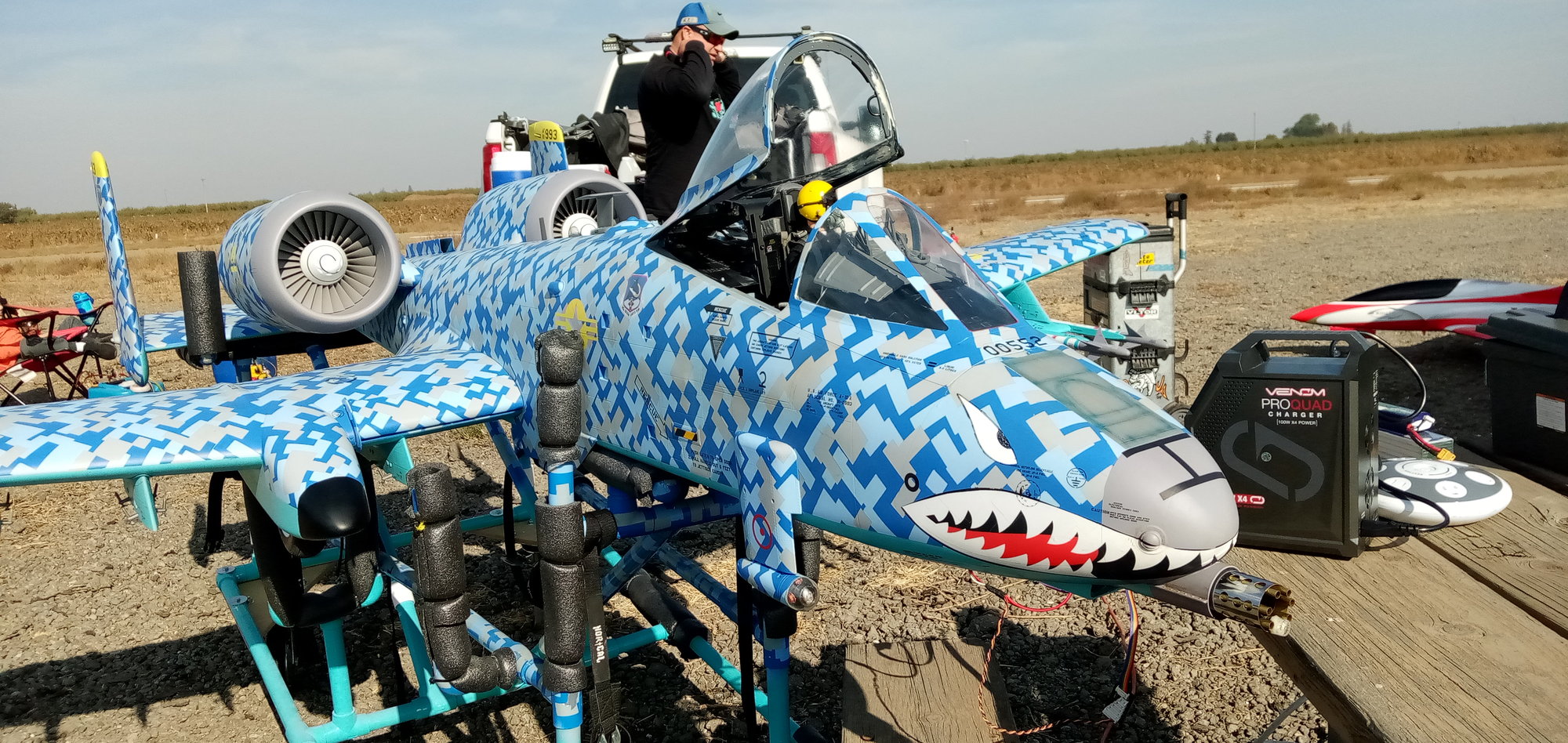
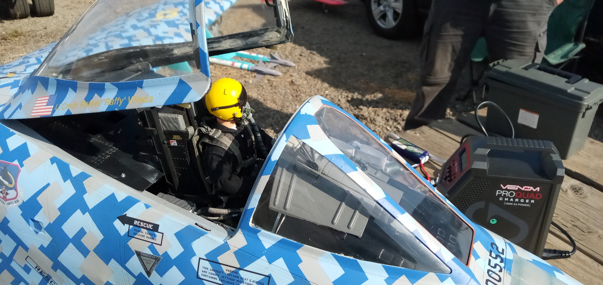
My mibo FOR SURE noses over with throttle more than it balloons at idle. Jack’s mix may have helped with my nosing over and the gyro also helped.
I first noticed how it wants to nose over at take off. If I relax on the elevator at rotation, it wants to dip the nose. I then noticed it again when I wanted to extend my final and I gently touched the throttle and it basically pitched down and touched down right at that spot.
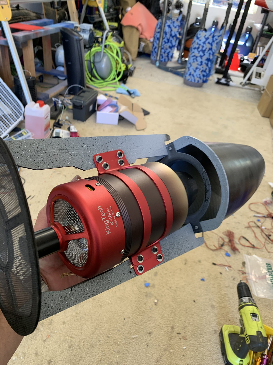
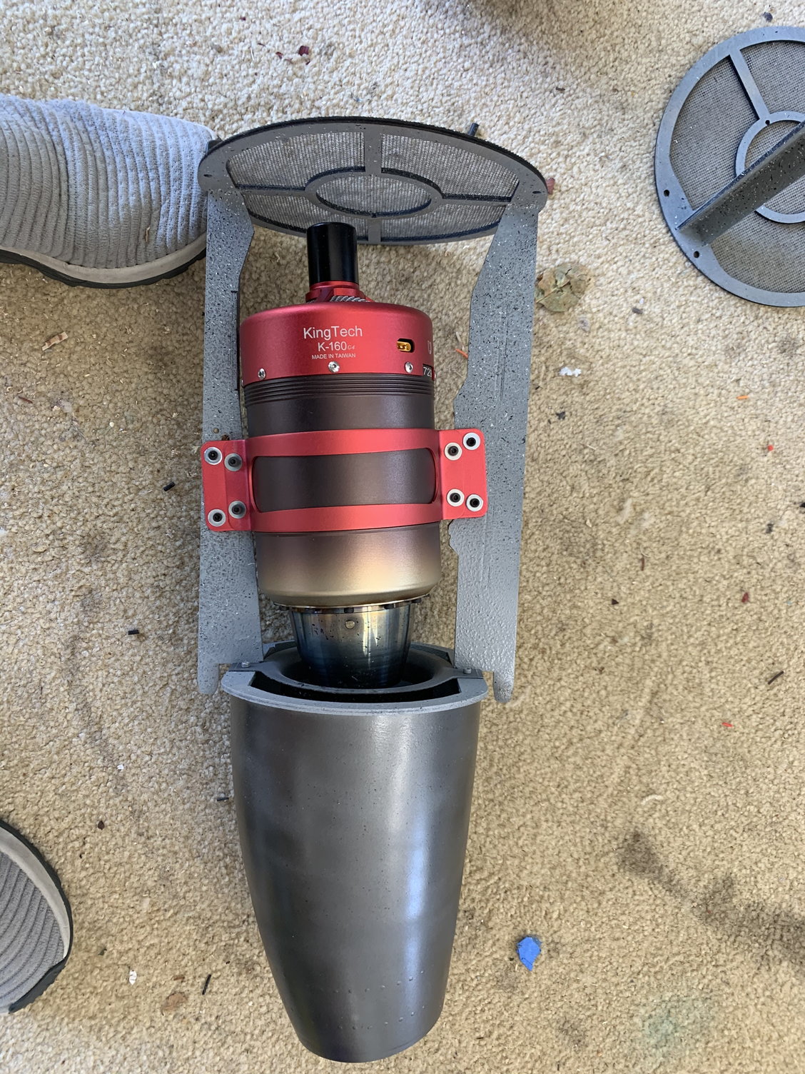
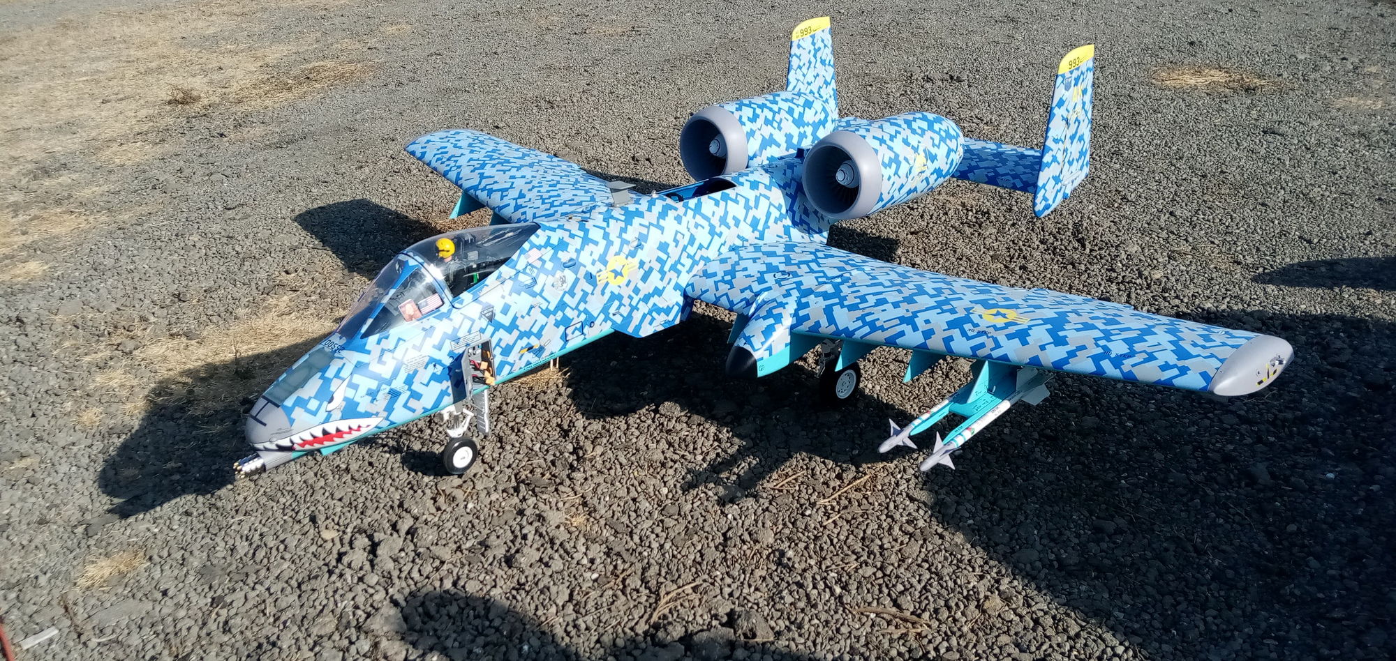
My turbines point up in the stock positions just like my pics in this very thread.
Oh, and my CG is at the factory recommended spot.
I first noticed how it wants to nose over at take off. If I relax on the elevator at rotation, it wants to dip the nose. I then noticed it again when I wanted to extend my final and I gently touched the throttle and it basically pitched down and touched down right at that spot.
My turbines point up in the stock positions just like my pics in this very thread.
Oh, and my CG is at the factory recommended spot.
11-13-2020, 10:50 AM
#517
Wrong, in my view !
The airflow over the stab is accelerated by the engine flow increasing its velocity and creating a strong up force, nose down pitch, which needs to be compensated by, in effect, up elevator or stab . angle Remove this engine induced flow, these are high bypass fans, in the real jet and the elevator effect has to be reduced ior compensated . by nose down elevator or stab. angle. So reduce the thrust , reduce that nose up trim or stab. Angle by trimming nose down.
The relative position and sizes of the fullsize engines and the models. may explain the results.
A similar situation existed in the BVM Bobcat where exhaust gas accelerated the speed of airflow over the stab. Causing , at high power, a strong nose up pitch. Hence large down thrust angle on BobCats and King Cats to compensate.
But what would I know !
Last edited by David Gladwin; 11-13-2020 at 10:56 AM.
11-13-2020, 11:16 AM
#519
Oh I do, I listen to anyone and everyone from whom I can learn anything at all. I have done that in all my career. But after a whole career of flying and instructing on real jets for RAF. pilots and instructors, and airline captains, at the highest level, I make my own conclusions.
So thats my theory on pitch changes on the A10.
So, please Ravil dont dumb it down with your silly pictures, le it for once, have an intelligent discussion.
but, of course, this is RCU!
So thats my theory on pitch changes on the A10.
So, please Ravil dont dumb it down with your silly pictures, le it for once, have an intelligent discussion.
but, of course, this is RCU!
Last edited by David Gladwin; 11-14-2020 at 03:09 AM.
 11-13-2020, 11:33 AM
#521
My Feedback: (6)
Wrong, in my view !
The airflow over the stab is accelerated by the engine flow increasing its velocity and creating a strong up force, nose down pitch, which needs to be compensated by, in effect, up elevator or stab . angle Remove this engine induced flow, these are high bypass fans, in the real jet and the elevator effect has to be reduced ior compensated . by nose down elevator or stab. angle. So reduce the thrust , reduce that nose up trim or stab. Angle by trimming nose down.
The relative position and sizes of the fullsize engines and the models. may explain the results.
A similar situation existed in the BVM Bobcat where exhaust gas accelerated the speed of airflow over the stab. Causing , at high power, a strong nose up pitch. Hence large down thrust angle on BobCats and King Cats to compensate.
But what would I know !
The airflow over the stab is accelerated by the engine flow increasing its velocity and creating a strong up force, nose down pitch, which needs to be compensated by, in effect, up elevator or stab . angle Remove this engine induced flow, these are high bypass fans, in the real jet and the elevator effect has to be reduced ior compensated . by nose down elevator or stab. angle. So reduce the thrust , reduce that nose up trim or stab. Angle by trimming nose down.
The relative position and sizes of the fullsize engines and the models. may explain the results.
A similar situation existed in the BVM Bobcat where exhaust gas accelerated the speed of airflow over the stab. Causing , at high power, a strong nose up pitch. Hence large down thrust angle on BobCats and King Cats to compensate.
But what would I know !
11-13-2020, 12:04 PM
#522
My Feedback: (6)
From a closer look there�s another theory coming to my mind ..
It seems that the upper surface of the stabilizer is partially blocked effected by the turbulence of the nacelles, reducing airspeed in that area while the lower surface of the stabilizer is in a much streamlined airflow over it . Especially at low airspeed! Meaning an induced down force therefore a nose up pitch . When at higher airspeed that turbulence is somewhat becomes more streamlined and with the effect of the thrust line position higher that the fuselage center line causes a push over ( pitch down )
Perhaps the full size benefiting from different Reynolds # and therefore better overall aerodynamic characteristics combined with the exhaust outlet pointing up was enough to solve the phenomenon .
Seem like the model is suffering from an increased induced drag from the nacelles combined with lower Reynolds # with over all lower aerodynamic characteristics need more attention to the exhaust nozzles angles combined with a bit forward CG just to compensate the pitch up tendencies at lower airspeed ...
My friends A-10 is almost ready for maiden , so I guess my theory will be tested soon 😊
11-13-2020, 02:23 PM
#523
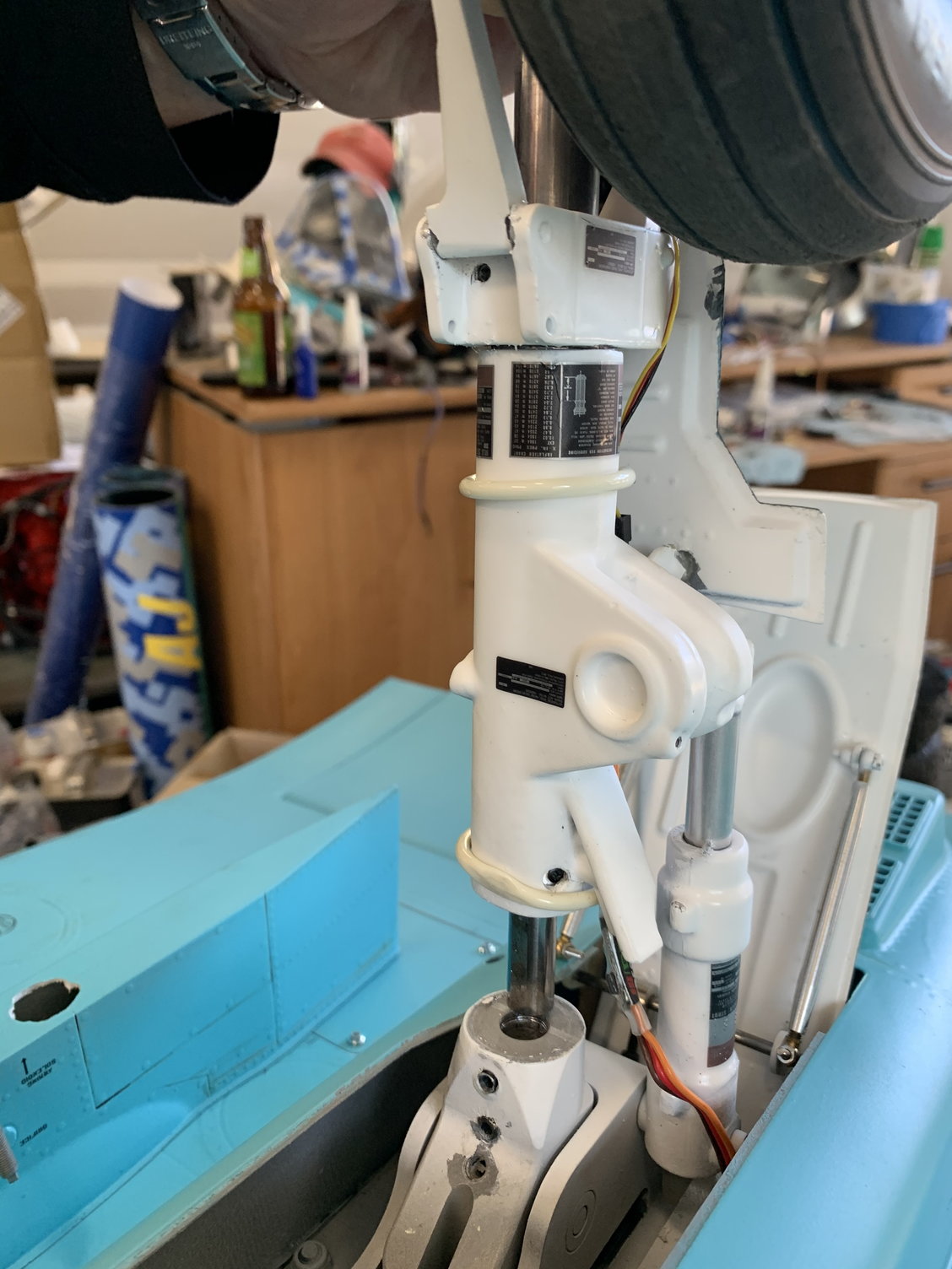
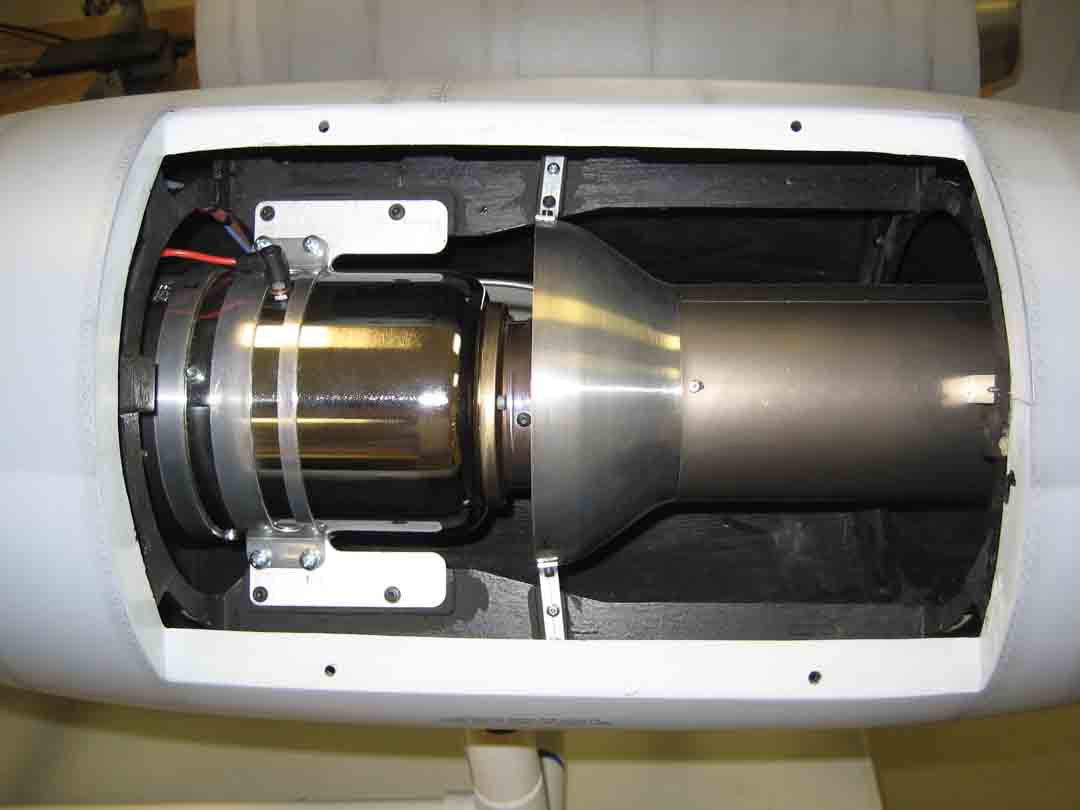
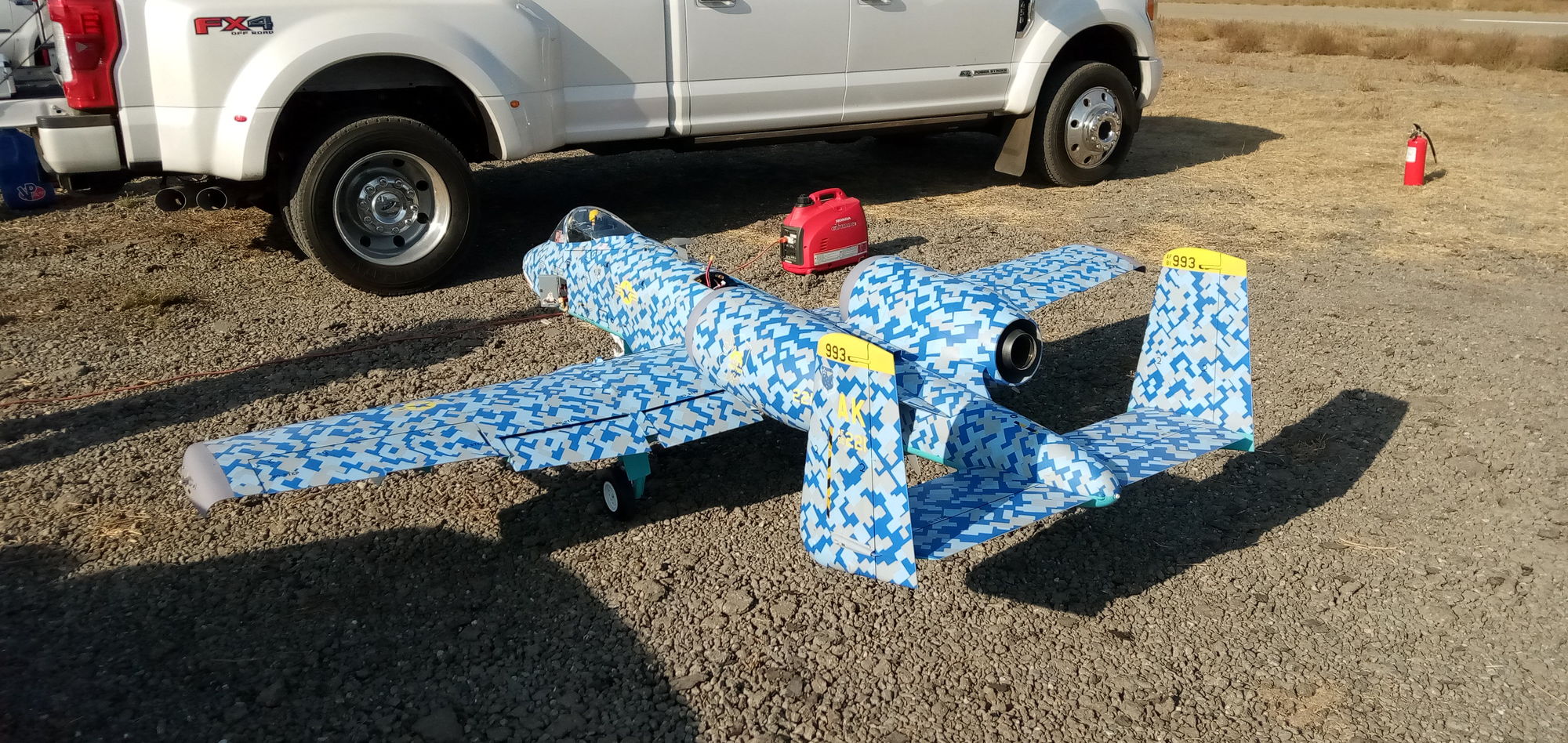
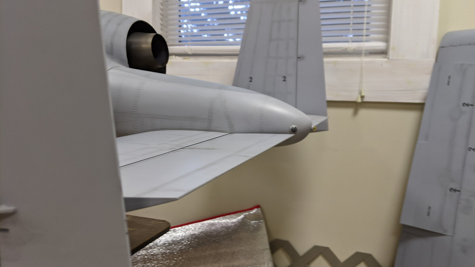
These theories all have merit but none would explain why my A-10 does not exhibit the thrust/pitch issue Rav is having. The obvious answer is that one or more relevant factors (i.e. thrust angle, stab incidence, cg, etc..) is different between the two. FWIW, I don't recall any of the earlier MIBO A-10's (up through gen 3), having this issue and I just wonder if MIBO changed something, even in a small way. For example, my stab has noticeable negative incidence and my elevators have always needed about 3/8" up trim for level flight. Maybe Rav can take a close look at these pics of mine and see if there is any obvious difference between his A-10 and mine.
I also know from flying a thrust vectored Eurosport that small amounts of thrust vector angle can have a significant effect. It may be that the thrust angle on his A-10 is only slightly different than mine but enough to cause the pitching. Anyhow, I don't think any of these things can be easily changed on a completed model and the trim compensation still seems like a good solution.
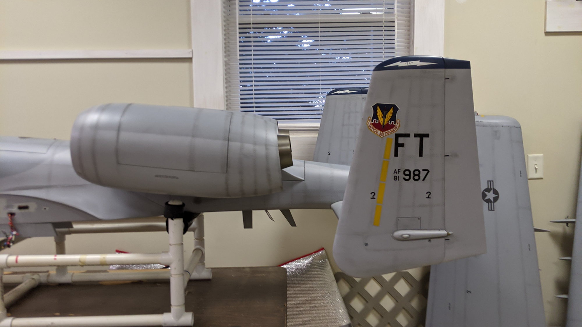
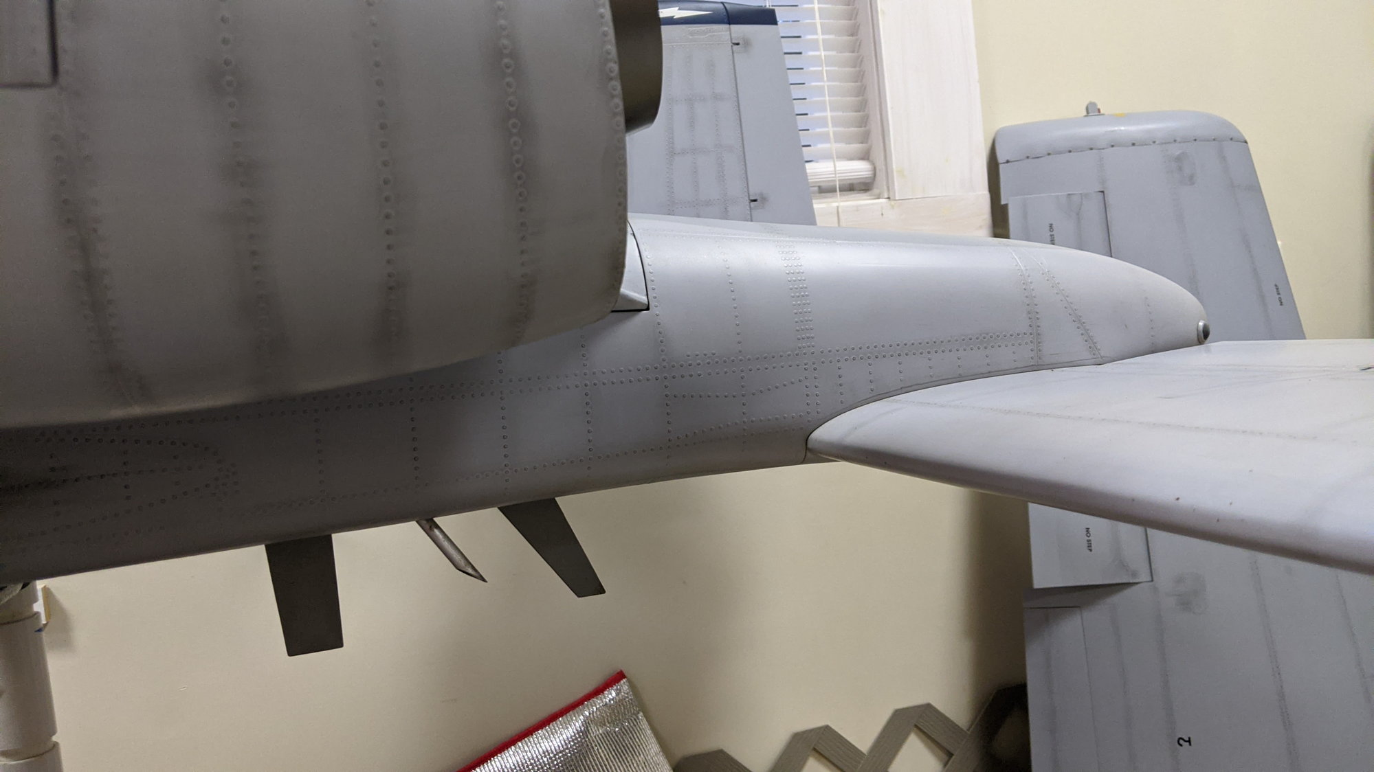
I also know from flying a thrust vectored Eurosport that small amounts of thrust vector angle can have a significant effect. It may be that the thrust angle on his A-10 is only slightly different than mine but enough to cause the pitching. Anyhow, I don't think any of these things can be easily changed on a completed model and the trim compensation still seems like a good solution.
11-13-2020, 04:19 PM
#524
No one means any disrespect when we are talking about our toy airplanes, so if someone gets offended, I apologize and others apologize too! Its all good!
And I like silly pics, so likely more are coming!
Craig, I can tell that your exhausts are higher in the rear of the nacelles and my elevators sit pretty much at neutral for flight. I'll double check though. I don't remember alot of up trim on maiden.
Let me go back and post pics of my exhaust.