


1/6 F-105 Build Thread
 01-07-2019, 06:44 PM
#251

Thread Starter
My Feedback: (20)
Many thanks for all the inputs. All new info for me and I continue to learn from all you guys. I really appreciate the info sharing on these forums.
First, my research showed that carbon was way more expensive than aluminum. In addition, do not know anything about carbon parts design. I was also concerned about trying to cut and deal with the carbon dust. With the questions of drilling, shock loads, bending, and work hazards I made the decision to stick with aluminum. The weight penalty is small % of the total weight of a jet this size.
Today I called onlinemetals.com to return the bent piece they sent and after some calls and emails they are sending me two pieces of 1/8" aluminum for the double layer spar at no additional cost. They do not accept returns of custom cut pieces and since the piece they first sent was defective they just said keep it and will replace the order with the two 1/8" pieces. They will also cut each to length.
So the plan is to make a double layer spar from two 1/8" thick pieces with the top piece extending just to the first wing bolts in the wheel well. The bottom piece will extend all the way out to the second set of bolts in the wheel well. This will give the full 1/4" thickness in the center clamped together by 8 bolts, and save 3" worth of weight on each end.
Thanks again for all the inputs.
Gary
 01-07-2019, 06:59 PM
#252


I personally dont like carbon parts for wing attachments that have landing gear mounted in the wings. I�ve seen shock loads imparted into CF parts delaminate and/or crack and it not be noticed until the part failed.
I would much rather use and suffer from a slightly heavier/beefier piece of metal that will just bend.
Thats just my personal preference though.
I would much rather use and suffer from a slightly heavier/beefier piece of metal that will just bend.
Thats just my personal preference though.
 01-07-2019, 08:40 PM
#253

Metal is a safer bet unless you're a composite expert and/or have a lot of composite experience.
Bob
 01-08-2019, 05:22 PM
#255
Thread Starter
My Feedback: (20)
Started working on stab system today.
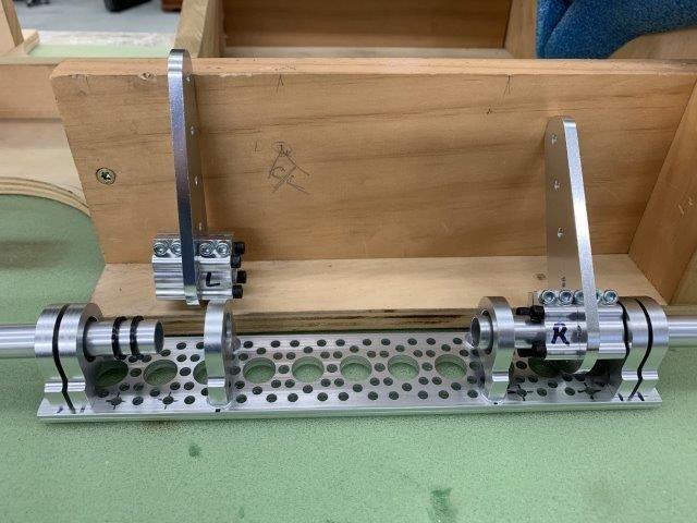
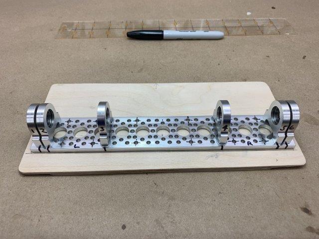
Step one was to get these parts working. At first anytime I would tighten the bearing block bolts it would bind the shaft. It would rotate freely in the ball bearings but would be impossible to remove. Apparently there were some tight tolerances and anytime the bolts were tightened it would induce a binding angle in the parts. After about two hours of fussing with it I slightly enlarged the bolt holes in the plate and shimmed up the inside blocks and got it working good. Now you can slide the tubes in and out easily. There are two nylon spacers between the clamp hubs and the 2nd bearing block to ensure they do not rub.

Step two was to see if the pipe had clearance from the bearing blocks. I taped the stab system parts to the plywood tray and mounted the pipe. It had clearance but just barely. I had to remove one of the clamp hubs in my first design to get the inside bearing block to move away from the pipe enough to provide clearance. The only function of that hub was to stop the tube from moving farther toward the center. Now that function will have to be the root of the stab against the nylon spacer on the outside of the fuse. Not enough room to fit the clamp hub inside plus it saved a little weight.
Step one was to get these parts working. At first anytime I would tighten the bearing block bolts it would bind the shaft. It would rotate freely in the ball bearings but would be impossible to remove. Apparently there were some tight tolerances and anytime the bolts were tightened it would induce a binding angle in the parts. After about two hours of fussing with it I slightly enlarged the bolt holes in the plate and shimmed up the inside blocks and got it working good. Now you can slide the tubes in and out easily. There are two nylon spacers between the clamp hubs and the 2nd bearing block to ensure they do not rub.
Step two was to see if the pipe had clearance from the bearing blocks. I taped the stab system parts to the plywood tray and mounted the pipe. It had clearance but just barely. I had to remove one of the clamp hubs in my first design to get the inside bearing block to move away from the pipe enough to provide clearance. The only function of that hub was to stop the tube from moving farther toward the center. Now that function will have to be the root of the stab against the nylon spacer on the outside of the fuse. Not enough room to fit the clamp hub inside plus it saved a little weight.
Last edited by Viper1GJ; 01-08-2019 at 05:26 PM.
01-08-2019, 05:45 PM
#256
Thread Starter
My Feedback: (20)
Locating the stab plate.
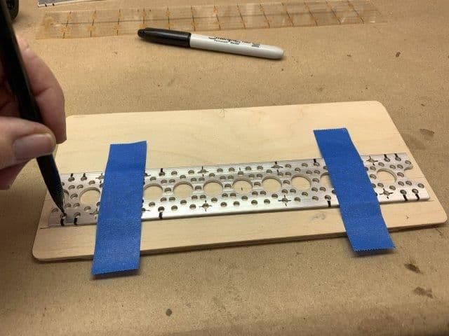
Locating the stab plate on the tray was difficult because the socket bolt heads stuck out of the bottom of the plate and it was impossible to insert the 1/2" aluminum tubes through the fuse holes and bearing blocks to get an accurate location. The solution turned out easy after I figured out the way. I inserted a smaller diameter 10 mm carbon tube through the fuses holes and into the bearings. This centered the bearings on the tube and allowed the edges of the plate to be marked.

The edges of the plate were traced while the carbon tube held everything on center.

Location lines on tray
Bolt head relief hole centers marked with plate taped in position
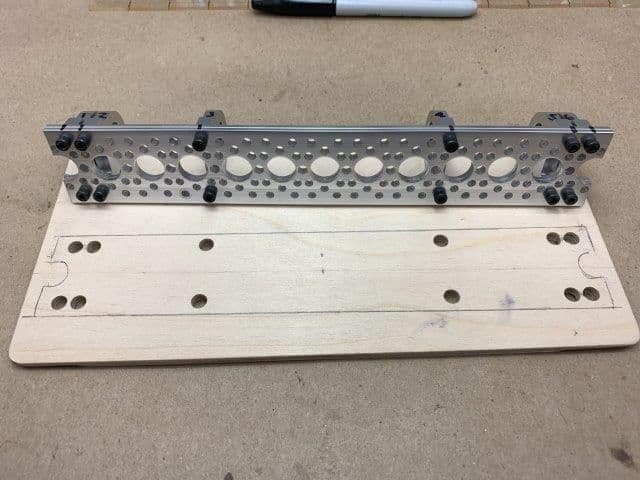
Bolt head relief holes drilled
The bolt head relief holes allowed the bearing plate to sit flat on the tray. The oversize holes allow the plate to shift slightly so that the plate mounting holes can be accurately marked once in position.
Locating the stab plate on the tray was difficult because the socket bolt heads stuck out of the bottom of the plate and it was impossible to insert the 1/2" aluminum tubes through the fuse holes and bearing blocks to get an accurate location. The solution turned out easy after I figured out the way. I inserted a smaller diameter 10 mm carbon tube through the fuses holes and into the bearings. This centered the bearings on the tube and allowed the edges of the plate to be marked.
The edges of the plate were traced while the carbon tube held everything on center.
Location lines on tray
Bolt head relief hole centers marked with plate taped in position
Bolt head relief holes drilled
The bolt head relief holes allowed the bearing plate to sit flat on the tray. The oversize holes allow the plate to shift slightly so that the plate mounting holes can be accurately marked once in position.
01-08-2019, 06:02 PM
#257
Thread Starter
My Feedback: (20)
Mounting stab plate
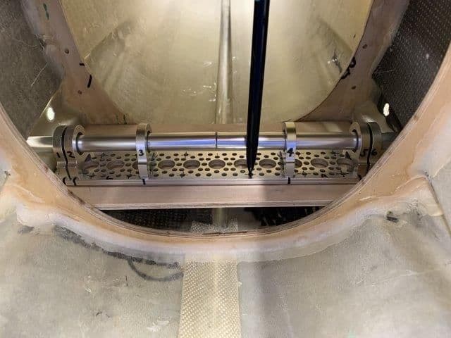
With stab plate sitting loosely in the bolt head relief holes it was installed with the 1/2" aluminum tubes. The tubes held the plate in position and allowed an accurate marking of the plate mounting holes.
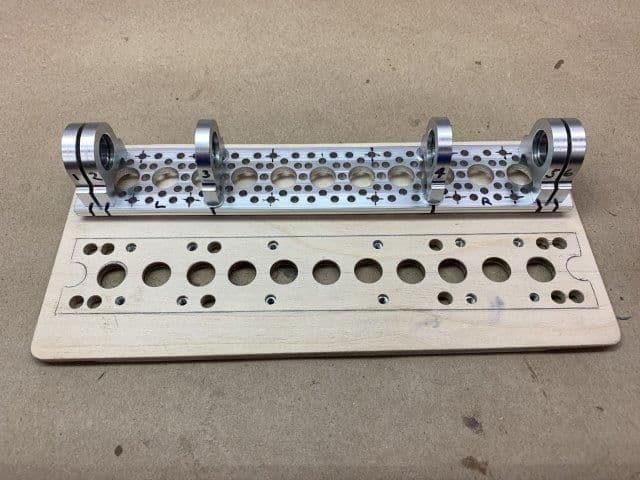
Plate mounting holes and some lightening holes to match the plate drilled. 6-32 blind nuts installed in mounting holes
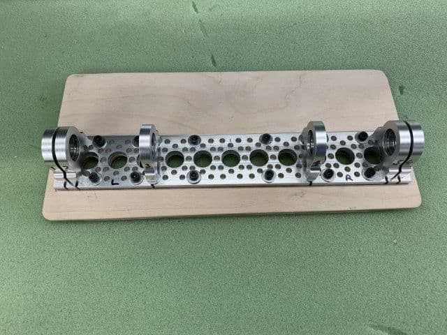
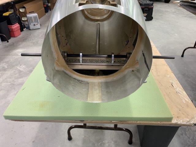
Stab plate bolted to the plywood tray

Stab tray installed and tubes and control horns installed
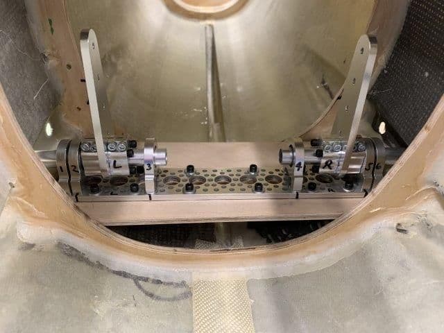
It actually worked pretty well.

I will have to cut the control horns shorter after I do calculations to determine the needed length.
With stab plate sitting loosely in the bolt head relief holes it was installed with the 1/2" aluminum tubes. The tubes held the plate in position and allowed an accurate marking of the plate mounting holes.
Plate mounting holes and some lightening holes to match the plate drilled. 6-32 blind nuts installed in mounting holes
Stab plate bolted to the plywood tray
Stab tray installed and tubes and control horns installed
It actually worked pretty well.
I will have to cut the control horns shorter after I do calculations to determine the needed length.
01-08-2019, 06:12 PM
#258
Thread Starter
My Feedback: (20)
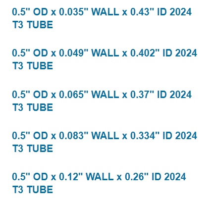
I will not use the Actobotics thin walled tubes because I dont know what they are made of and they don't feel very strong. I will order new stab tubes.
My question is what wall thickness to use. Below are my choices. Any recommendations from "metal smart guys" appreciated.
Thanks,
Gary
My question is what wall thickness to use. Below are my choices. Any recommendations from "metal smart guys" appreciated.
Thanks,
Gary
01-12-2019, 04:35 PM
#259
Thread Starter
My Feedback: (20)
Wing spar plates showed up this week. Did not get to them at all because of a septic tank disaster. After all the rain here for the last 3 weeks and a malfunctioning inlet in the septic tank, you know what backed up into the shop drain. All is fixed and well now but it wasn't pretty for a couple of days.
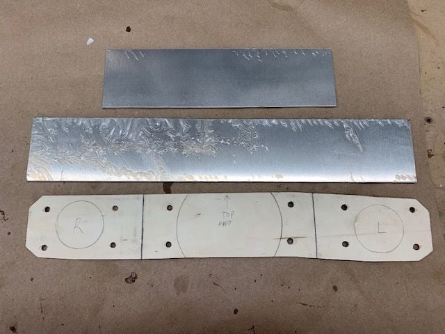
The 1/8" spar plates and pattern ready for cutting and drilling.
Also ordered the stab tubes and they should arrive next week.
The 1/8" spar plates and pattern ready for cutting and drilling.
Also ordered the stab tubes and they should arrive next week.
01-13-2019, 06:35 AM
#260
Banned
I will not use the Actobotics thin walled tubes because I dont know what they are made of and they don't feel very strong. I will order new stab tubes.
My question is what wall thickness to use. Below are my choices. Any recommendations from "metal smart guys" appreciated.
Thanks,
Gary
My question is what wall thickness to use. Below are my choices. Any recommendations from "metal smart guys" appreciated.
Thanks,
Gary
The Actobotics tube is .030 thick or just shy of 1/32 inch. I think they should be OK for my purposes but I have thicker on hand if I change my mind.
01-13-2019, 02:30 PM
#261
Thread Starter
My Feedback: (20)
Oli recommended AL 7075 with 3mm wall. I could not find any 7075 tubing only solid rod. So 2024 was second choice with .5" OD and .12" wall. I don't know how to calculate any flying forces but I's sure 2024 with a 1/8" wall will be plenty strong. It also has more "meat" to hold the torque transfer pins inside the stab.
01-15-2019, 06:31 PM
#262
Thread Starter
My Feedback: (20)
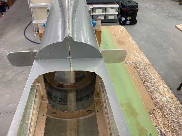
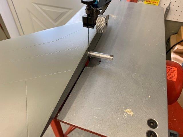
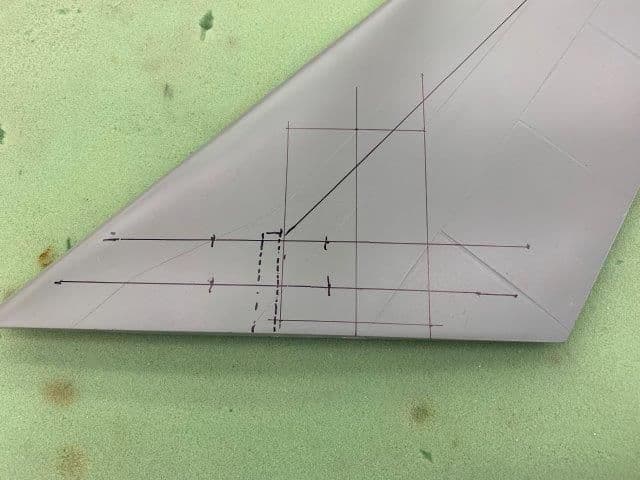
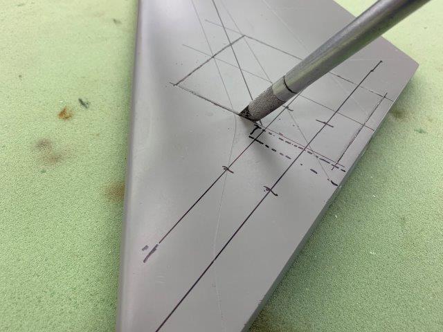
I cut spar plates and opened up wing former for more air to turbine.
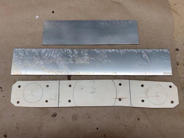
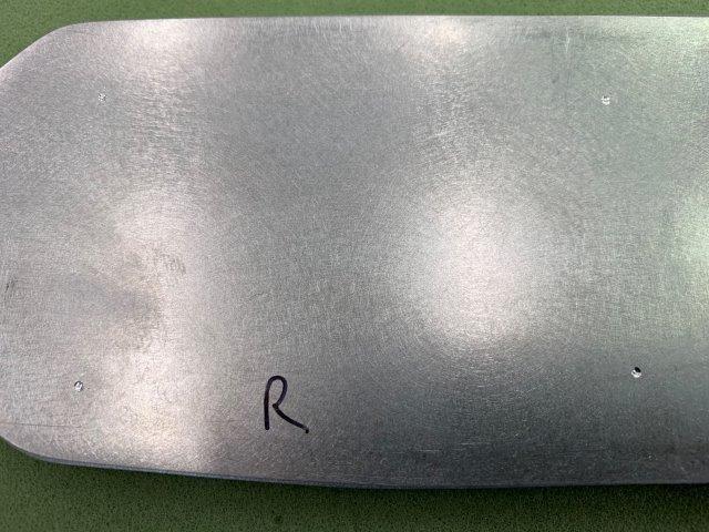
AL 7075 1/8" spar plates arrived, pattern shown below

Cutting plates to shape turned out to be fairly easy. I used a 17 TPI metal blade on slow speed with some bees wax. Slow feed rate but pretty easy overall.
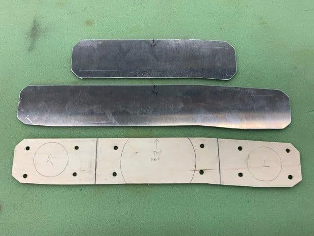
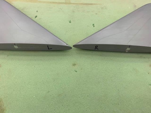
Plates cut to shape
Plates glued together with hysol

Dremel saw used to make cuts in 1/2" ply wing former. The total area of hole was scientifically calculated by using straight lines to connect the bottom hole and a paint can to trace the upper hole!
Straight plunge cuts used on upper hole

Dremel permagrit grinder and drum sander used to finish the shape of the upper hole.
AL 7075 1/8" spar plates arrived, pattern shown below
Cutting plates to shape turned out to be fairly easy. I used a 17 TPI metal blade on slow speed with some bees wax. Slow feed rate but pretty easy overall.
Plates cut to shape
Plates glued together with hysol
Dremel saw used to make cuts in 1/2" ply wing former. The total area of hole was scientifically calculated by using straight lines to connect the bottom hole and a paint can to trace the upper hole!
Straight plunge cuts used on upper hole
Dremel permagrit grinder and drum sander used to finish the shape of the upper hole.
01-15-2019, 06:52 PM
#263
Thread Starter
My Feedback: (20)
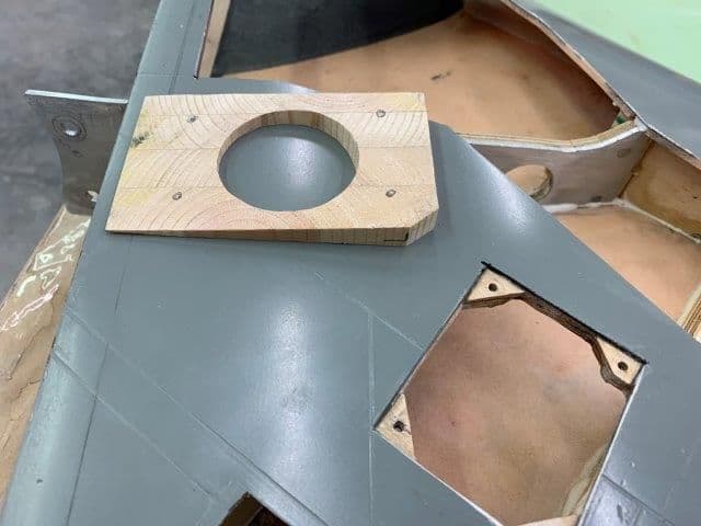
Mounting the spar on fuse former

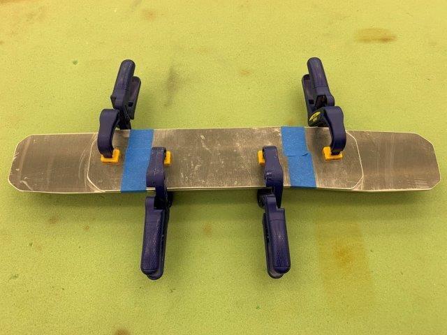
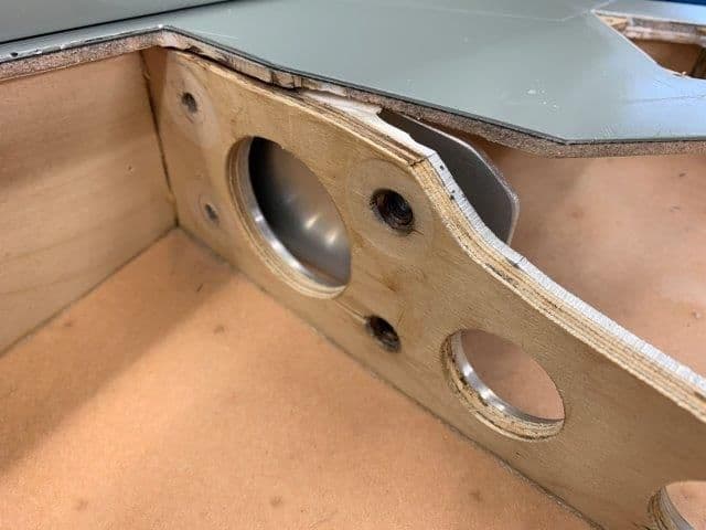
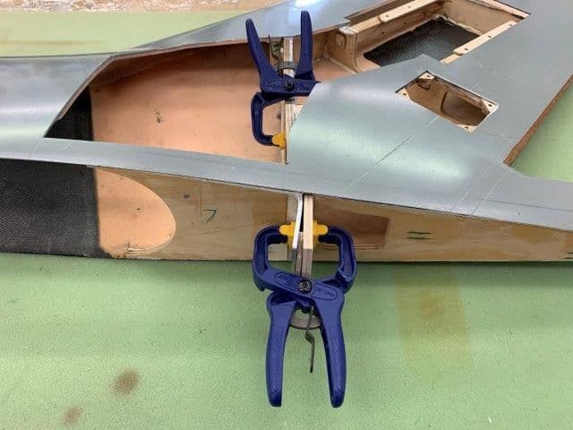
Spar center holes drilled, smoothed edges, ready to mount
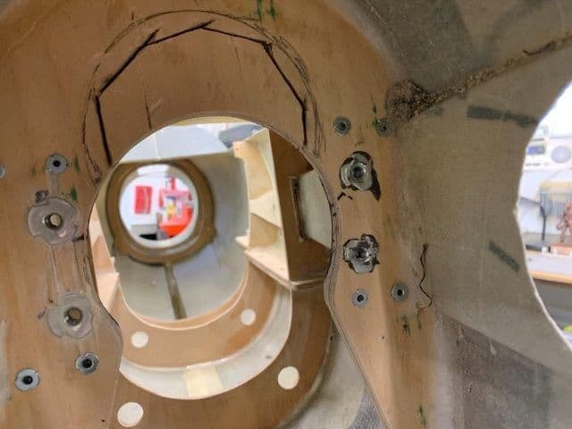
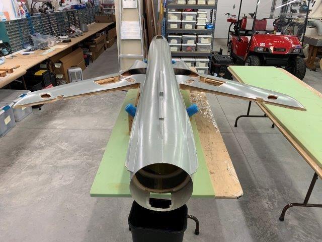
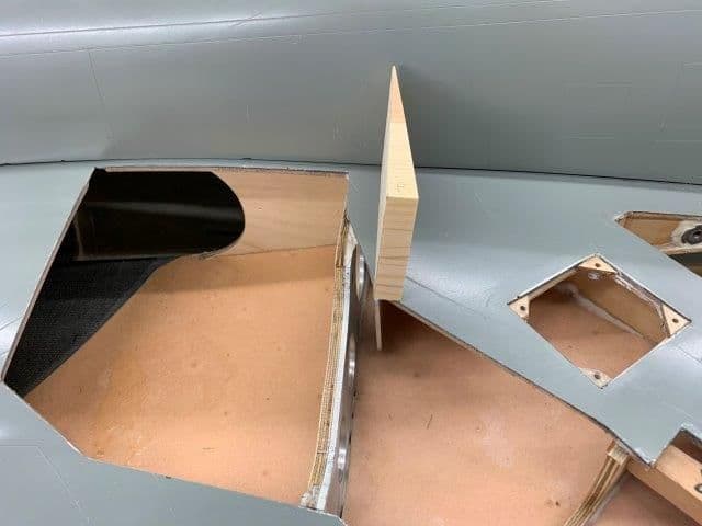
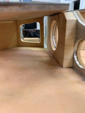
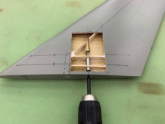
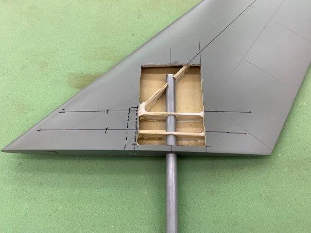
Spar across wing former with new air holes opened up. Should be plenty of air to turbine. I may try to make a smooth aero shape in front of spar to smooth airflow over and under the spar
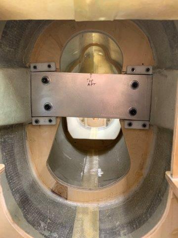
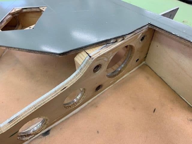
Spar extends out into each wing now

Double thickness extends only to first bolts in the wing gear well to save weight
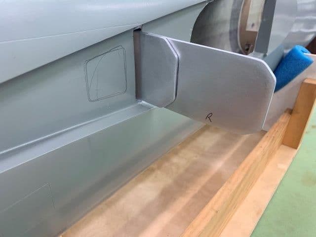
Same on right side
Root rib spar slots widened to accept spar doubler
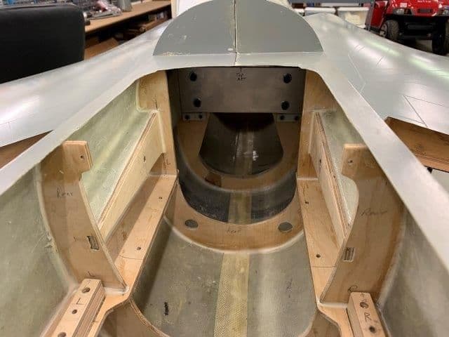
Wings test mounted onto fuse with new spar. This mod solved my biggest fear, of breaking off a a wing in normal flight with nothing but plywood holding the wings on. Many thanks to everyone who helped with ideas and recommendations
Gary
Spar center holes drilled, smoothed edges, ready to mount
Spar across wing former with new air holes opened up. Should be plenty of air to turbine. I may try to make a smooth aero shape in front of spar to smooth airflow over and under the spar
Spar extends out into each wing now
Double thickness extends only to first bolts in the wing gear well to save weight
Same on right side
Root rib spar slots widened to accept spar doubler
Wings test mounted onto fuse with new spar. This mod solved my biggest fear, of breaking off a a wing in normal flight with nothing but plywood holding the wings on. Many thanks to everyone who helped with ideas and recommendations
Gary
01-15-2019, 07:07 PM
#264
Thread Starter
My Feedback: (20)
Happy snap of jet upside down with wings on.
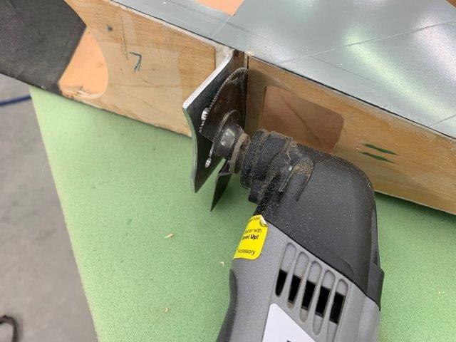
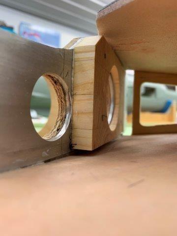
There is a 1/2" gap between the new spar and the existing spar in the wing
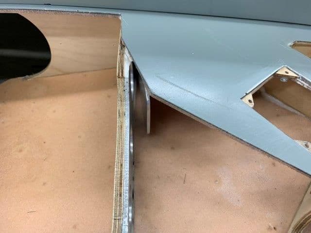
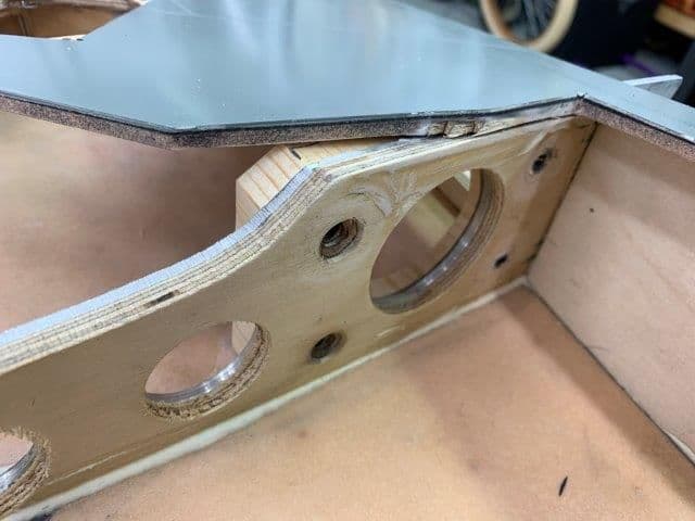
Side view of gap. I fabricated a hard wood wedge to fill the gap and allow the spars to be securely bolted together.
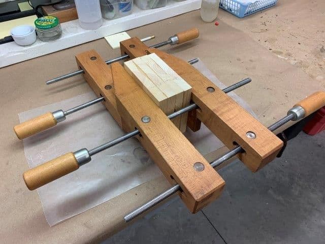
4 pieces of 1 x 6 pine laminated together with 30 min epoxy to make wedges with end grain to hold spar bolt pressure. The big block was for me to hold on to while cutting on table saw with 3" depth of cut.
The laminated block was squared up on table saw and the wedges cut from one end for an end grain wedge

Rough cut wedge ready for dry fitting
Right side shaped and cut
Left wedge shaped and cut ready for insrall
01-15-2019, 07:17 PM
#265
Thread Starter
My Feedback: (20)
Dry fitting wedges
Wedge will be glued to aluminum spar with hysol
From bottom
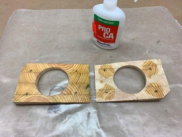
Wedges end grain hardened with thin CA around bolt holes and then all over
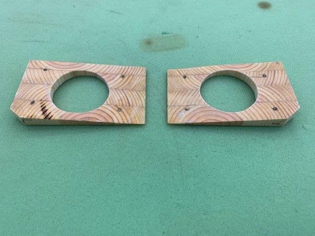
Wedges ready for install
Wedge will be glued to aluminum spar with hysol
From bottom
Wedges end grain hardened with thin CA around bolt holes and then all over
Wedges ready for install
01-16-2019, 03:52 AM
#266

I will not use the Actobotics thin walled tubes because I dont know what they are made of and they don't feel very strong. I will order new stab tubes.
My question is what wall thickness to use. Below are my choices. Any recommendations from "metal smart guys" appreciated.
Thanks,
Gary
My question is what wall thickness to use. Below are my choices. Any recommendations from "metal smart guys" appreciated.
Thanks,
Gary
David
 01-16-2019, 06:08 PM
#269
Thread Starter
My Feedback: (20)
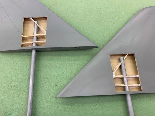
The stab pivot tubes from McMaster Carr arrived to day so I started working on stabs while waiting for wing wedges to cure.
Step one was to cut off the existing stab pivot rod.
Well we're committed now to a new stab pivot tube!

Next was to mark and drill the new hole for the stab pivot tube. I marked the circle and then used a step drill making sure the hole was centered in the process.
Next I marked a cut out on the bottom of the stab. The ribs and spar lines were marked earlier my my friend who put them through an Xray machine last year.
A large Xacto blade was used to make the cuts through the fiberglass and airex layers

I had hoped to save the cutout but it was impossible to remove without destroying it. Here is the opening after being cleaned up a bit with a dremel and permagrit tool. I was very pleased to find nothing complicated inside which should make installing the new tube pretty simple. The opening will probably get covered with thick balsa and sanded to shape and glassed.
The step drill has a hex drive and was attached to an extension which made drilling all the way in very easy.
The new stab tube dry fit in place. Overall I'm relieved after opening the stab that there are no surprises and it should be fairly easy to make the modification.
Step one was to cut off the existing stab pivot rod.
Well we're committed now to a new stab pivot tube!
Next was to mark and drill the new hole for the stab pivot tube. I marked the circle and then used a step drill making sure the hole was centered in the process.
Next I marked a cut out on the bottom of the stab. The ribs and spar lines were marked earlier my my friend who put them through an Xray machine last year.
A large Xacto blade was used to make the cuts through the fiberglass and airex layers
I had hoped to save the cutout but it was impossible to remove without destroying it. Here is the opening after being cleaned up a bit with a dremel and permagrit tool. I was very pleased to find nothing complicated inside which should make installing the new tube pretty simple. The opening will probably get covered with thick balsa and sanded to shape and glassed.
The step drill has a hex drive and was attached to an extension which made drilling all the way in very easy.
The new stab tube dry fit in place. Overall I'm relieved after opening the stab that there are no surprises and it should be fairly easy to make the modification.
 01-17-2019, 05:57 PM
#271
Thread Starter
My Feedback: (20)
Yes it did. I am no longer worried about blowing off a wing mounted in plywood.
I used the diagram in the AMA LMA document to calculate the MAC. I set the pivot point at 23% MAC base on their recommendations.
Gary
01-17-2019, 06:11 PM
#272
Thread Starter
My Feedback: (20)
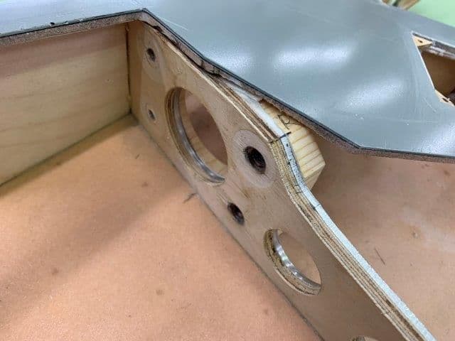
Wing wedges glued in with hysol and drilled.

Right side from inside wheel well
Left side
Right side from bottom of wing
Left side
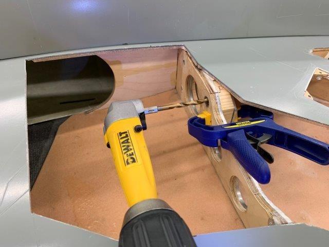
Marking bolt hole centers on spar plate with drill.
Drill points marked on spar plate will be drilled on drill press
Right side from inside wheel well
Left side
Right side from bottom of wing
Left side
Marking bolt hole centers on spar plate with drill.
Drill points marked on spar plate will be drilled on drill press
01-17-2019, 07:02 PM
#273
Thread Starter
My Feedback: (20)
I got both stab bottoms opened up and got pivot tubes dry fitted in place. Tubes set at 90� to chord line allow rotation on fuse OK. however the next problem will be to get the stabs lined up square with wings. They are slightly off when viewed from tail. I will have to jig up fuse with bubble levels again like when setting wing anhedral and set the stabs level with wings. As discussed before there is nothing straight or square with this build so I will just have to get it as close as possible.
01-18-2019, 05:56 AM
#275
I got both stab bottoms opened up and got pivot tubes dry fitted in place. Tubes set at 90� to chord line allow rotation on fuse OK. however the next problem will be to get the stabs lined up square with wings. They are slightly off when viewed from tail. I will have to jig up fuse with bubble levels again like when setting wing anhedral and set the stabs level with wings. As discussed before there is nothing straight or square with this build so I will just have to get it as close as possible.
I would machine a solid piece of aluminum as a rod insert where the pins pass through, just for the pins. You can hysol it in place.
David

