


1/6 F-105 Build Thread
 02-04-2021, 05:44 PM
#876

Thread Starter
My Feedback: (20)
Balancing the wheels and tires
Since I could not continue the landing gear testing without the JMP valve I moved on to the wheels. They were found to be grossly out of balance during the initial drag chute Lua program testing last year. I was able to get them up to about 40 mph with the electric drill and they just about shook off the table.
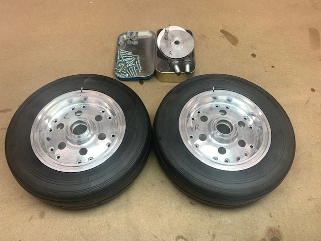
I asked Larry to look at a way to balance the wheels and tires and he found a method that was pretty easy so I followed his lead. I got the wheels off the struts and took all the screws out but could not separate the wheel halves. I was afraid to use a screwdriver under the rubber for fear of damaging the wheel but Larry said that's what worked. It turned out to be pretty easy after that.
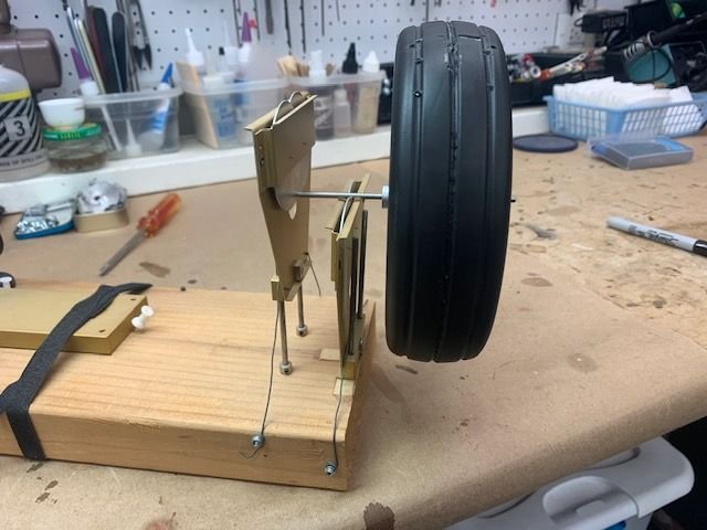
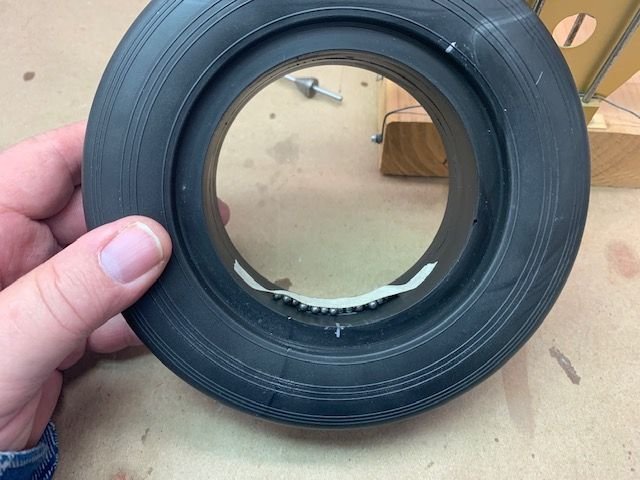
I put the wheel and tire on the High Point balancer and quickly found the heavy side.
I marked the tire and wheel so I could re-assemble it the same way each time.

I marked the top after the heavy side was down showing where the balance weight should go

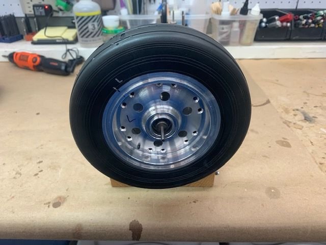
I transferred the mark to the inside of the tire showing where the balance weights should go. I also marked the area between the two wheel hubs.
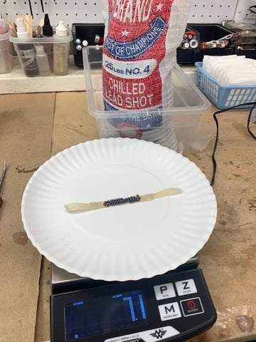
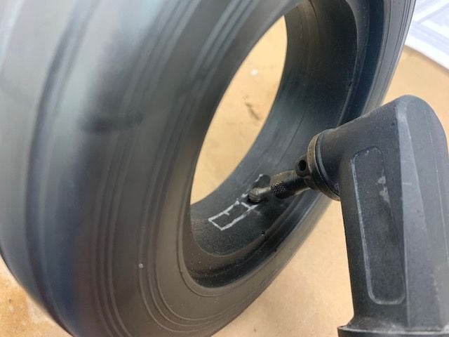
After a couple of tries I had about 7 grams of lead shot on the tape strip
The tape was placed inside the tire and then on the balancer. Trial and error wound up with about 7 grams.

The area covered by the lead shot was marked
A ball Dremel cutter was used to remove the rubber inside the marked area
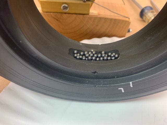
Lead shot poured in the recessed cutout
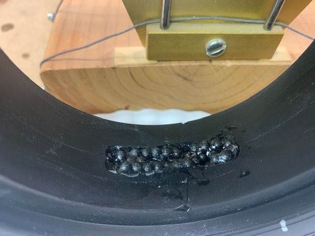
Goop used to glue in the lead shot. I assembled the wheel hubs and tested again and I had to remove about 8 shot to get the balance right after the Goop was added. Hopefully the Goop will cure with out losing much weight. I will recheck after the Goop dries. One done, one to go!
Thanks for the tips Larry.
Malcolm, Loctite 638 ordered. Thank for the advice.
Larry is also working on some ways to hold the main gear strut up inside the wheel well so that the gear doors can be flush or at least closer to the bottom wing skin. Hopefully something can be made to solve the gear droop problem.
My finger is on the mend, almost ready for the next dumb move!
Since I could not continue the landing gear testing without the JMP valve I moved on to the wheels. They were found to be grossly out of balance during the initial drag chute Lua program testing last year. I was able to get them up to about 40 mph with the electric drill and they just about shook off the table.
I asked Larry to look at a way to balance the wheels and tires and he found a method that was pretty easy so I followed his lead. I got the wheels off the struts and took all the screws out but could not separate the wheel halves. I was afraid to use a screwdriver under the rubber for fear of damaging the wheel but Larry said that's what worked. It turned out to be pretty easy after that.
I put the wheel and tire on the High Point balancer and quickly found the heavy side.
I marked the tire and wheel so I could re-assemble it the same way each time.
I marked the top after the heavy side was down showing where the balance weight should go
I transferred the mark to the inside of the tire showing where the balance weights should go. I also marked the area between the two wheel hubs.
After a couple of tries I had about 7 grams of lead shot on the tape strip
The tape was placed inside the tire and then on the balancer. Trial and error wound up with about 7 grams.
The area covered by the lead shot was marked
A ball Dremel cutter was used to remove the rubber inside the marked area
Lead shot poured in the recessed cutout
Goop used to glue in the lead shot. I assembled the wheel hubs and tested again and I had to remove about 8 shot to get the balance right after the Goop was added. Hopefully the Goop will cure with out losing much weight. I will recheck after the Goop dries. One done, one to go!
Thanks for the tips Larry.
Malcolm, Loctite 638 ordered. Thank for the advice.
Larry is also working on some ways to hold the main gear strut up inside the wheel well so that the gear doors can be flush or at least closer to the bottom wing skin. Hopefully something can be made to solve the gear droop problem.
My finger is on the mend, almost ready for the next dumb move!
Last edited by Viper1GJ; 02-04-2021 at 05:55 PM.
 02-10-2021, 03:51 PM
#878
Thread Starter
My Feedback: (20)
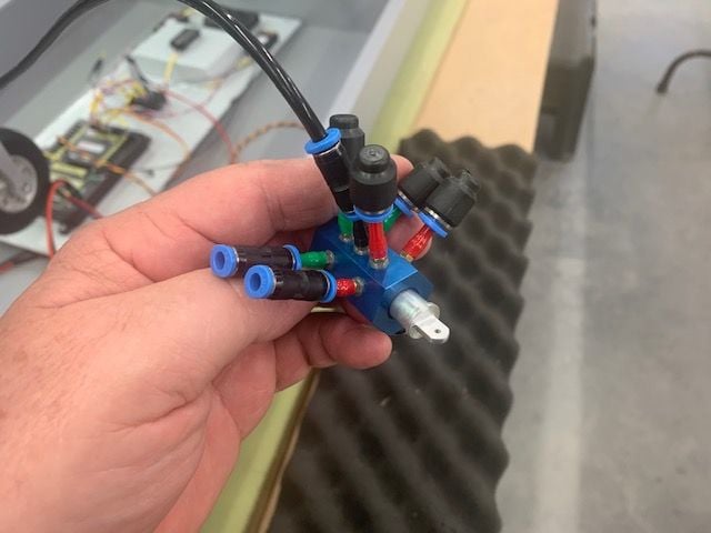
JMP gear valve test
The grandkids left and JMP 4mm gear valve and some connectors arrived. After some kid cleanup and reorganization I got back to testing the gear system.

I put the wheels back on the struts and then rigged up a manual test of the JMP valve using internal air to all three gear. The nose gear and right main worked well. The right main had plenty of force for lifting the big strut and wheel into the wheel well. The left main was unsatisfactory. It would barely lift up into the wheel well and probably would not have locked up with airspeed pushing it back.
I disconnected the nose and right main gear and capped the valve outputs. This put all the internal air pressure into the left main gear. No change. I removed the wing and started investigation by testing between the two tables with internal air directly into the gear from the valve bypassing the lines inside the fuse. No change. Next I used shop air directly into the up line. I cold see that the up cycle was weak and slow even with shop air directly into the red up line. Next I took the gear out of the wing and it seemed it was hard to swing up even by hand.
The grandkids left and JMP 4mm gear valve and some connectors arrived. After some kid cleanup and reorganization I got back to testing the gear system.
I put the wheels back on the struts and then rigged up a manual test of the JMP valve using internal air to all three gear. The nose gear and right main worked well. The right main had plenty of force for lifting the big strut and wheel into the wheel well. The left main was unsatisfactory. It would barely lift up into the wheel well and probably would not have locked up with airspeed pushing it back.
I disconnected the nose and right main gear and capped the valve outputs. This put all the internal air pressure into the left main gear. No change. I removed the wing and started investigation by testing between the two tables with internal air directly into the gear from the valve bypassing the lines inside the fuse. No change. Next I used shop air directly into the up line. I cold see that the up cycle was weak and slow even with shop air directly into the red up line. Next I took the gear out of the wing and it seemed it was hard to swing up even by hand.
02-10-2021, 04:19 PM
#879
Thread Starter
My Feedback: (20)
Left main gear disassembly
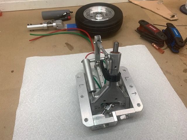
First I took the lower strut and wheel off to remove the weight. I had always just assumed the gear was stiff because of the weight of the strut, linkage, and big wheel so I wanted to remove the strut and wheel to feel the movement with out the weight. The movement still felt stiff.
Next I disconnected the air cylinder linkage to the strut to get rid of the drag of the linkage. It was still stiff.
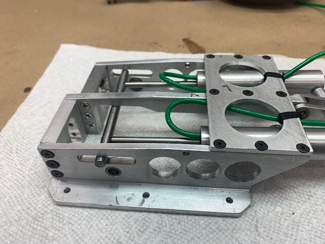
Without any linkage or heavy strut the only movement is in the pins going through the sides of the frame.
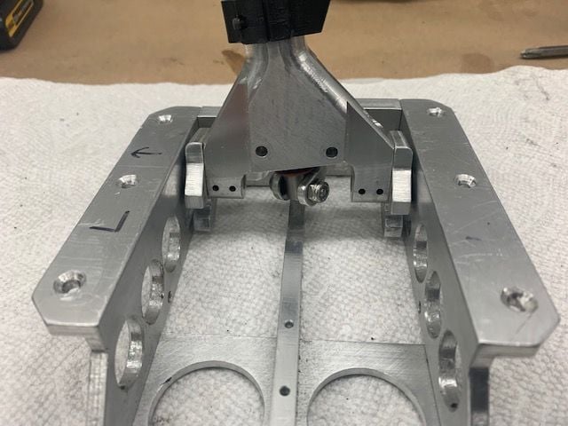
This was all that was left connected and it was binding the movement. This is probably the reason the gear will not retract properly.
It took about 30 min to get the screws out. They were glued in solid by thread locker probably since manufacture several years ago. I had to use a torch to heat the frame and screws to get the thread locker to let go.
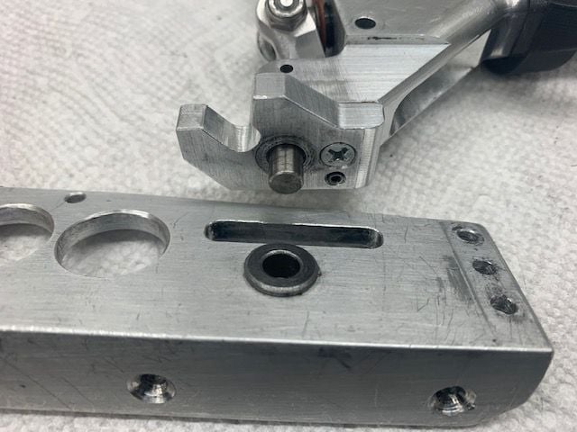
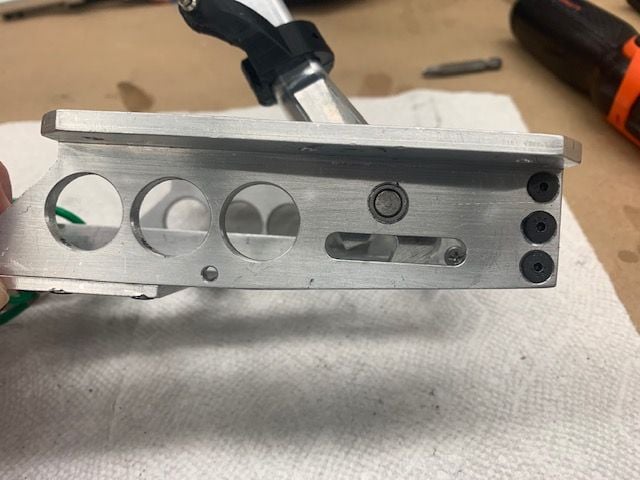
Here is the pin and bushing on one side
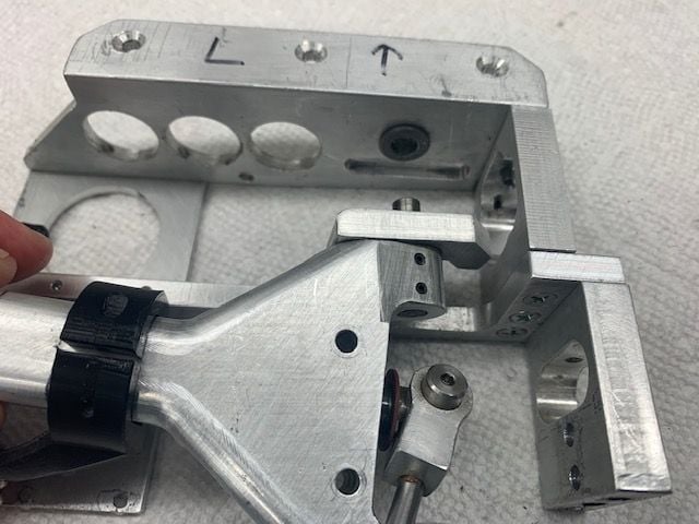
And the other side. The pins fit nicely and pivot freely when disassembled.

It seems that the pivot pins are not straight or the frame is not square.
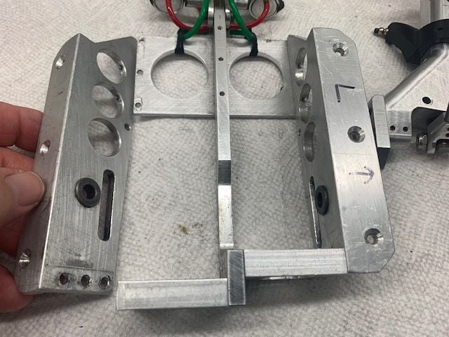
You can feel the pivot pins get tight as the frame screws are tightened so something is binding. The question is how to fix it. I was thinking about trying to enlarge the holes in the bushings but not really sure how to do it. I was afraid to try to drill it and make it too big and have the pivot pins wobble in the hole. Suggestions welcome.
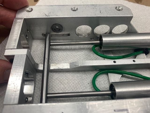
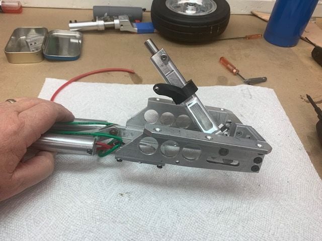
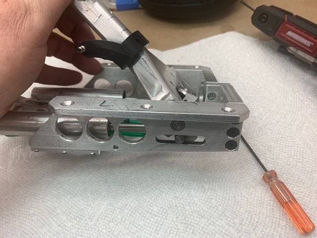
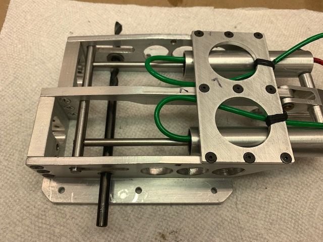
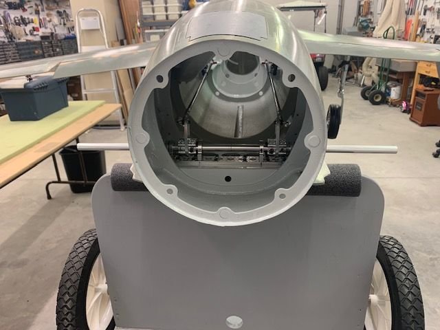
Here is the slide bar with out the strut in place

Air rams are threaded into the slide bar. There is a fair amount of resistance inside the cylinders but I have all ready applied some BVM silicon lube oil and you can here it squishing as you activate the cylinders. Not sure how I can loosen them up.
First I took the lower strut and wheel off to remove the weight. I had always just assumed the gear was stiff because of the weight of the strut, linkage, and big wheel so I wanted to remove the strut and wheel to feel the movement with out the weight. The movement still felt stiff.
Next I disconnected the air cylinder linkage to the strut to get rid of the drag of the linkage. It was still stiff.
Without any linkage or heavy strut the only movement is in the pins going through the sides of the frame.
This was all that was left connected and it was binding the movement. This is probably the reason the gear will not retract properly.
It took about 30 min to get the screws out. They were glued in solid by thread locker probably since manufacture several years ago. I had to use a torch to heat the frame and screws to get the thread locker to let go.
Here is the pin and bushing on one side
And the other side. The pins fit nicely and pivot freely when disassembled.
It seems that the pivot pins are not straight or the frame is not square.
You can feel the pivot pins get tight as the frame screws are tightened so something is binding. The question is how to fix it. I was thinking about trying to enlarge the holes in the bushings but not really sure how to do it. I was afraid to try to drill it and make it too big and have the pivot pins wobble in the hole. Suggestions welcome.
Here is the slide bar with out the strut in place
Air rams are threaded into the slide bar. There is a fair amount of resistance inside the cylinders but I have all ready applied some BVM silicon lube oil and you can here it squishing as you activate the cylinders. Not sure how I can loosen them up.

 02-10-2021, 11:06 PM
#882

Hi Gary,
I feel your pain! I have a colleague who is into field archery and in that hobby they have lots of parts that are “nearly engineered” as we call them. As you have discovered the pin/bush fit is fine but there is misalignment between now the bushes causing the binding. The problem is compounded by the fact that there are multiple joints across the unit from one side frame to the other and from the pics it doesn’t look like there is any location between these parts, relying on the screws to hold them together. If this was properly engineered there would be dowel pins locating the parts at each joint as it is not possible to accurately locate parts on threads.
The problem you have is that you might be able to get this to work by opening up the bush/pin clearance using a reamer but ideally you want to do this with the side frames bolted together as normal without the pivot block so that you can ream the holes in line. However when you take it apart to install the pivot block there is a chance the bushes won’t go back in line. I think also that the thread lock you found was an attempt to hold all the parts from moving once assembled and subjected to landing shocks. You could use the high strength retaining compound on this but getting the unit apart later will be difficult. Short of coming up with location dowels to hold the parts accurately in space I can’t see a better option than trying to open up the clearances and hope for the best.
I wish there was an easy solution!
Malcolm

 02-11-2021, 05:20 AM
#884
Hey Gary,
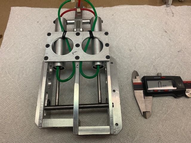
I’ve just looked at your pics again. One obvious source of misalignment of the two bushes is if the side frames are not truly parallel. It looks like the distance pieces at either end are actually made up of three components, the thickness of the central “spine” and then the two horizontal plates with holes in at one end and the spine and two vertical plates at the other end. So plenty of opportunity for tolerances to add up leading to the side plates not being parallel.
Do you have a vernier calliper? If so I would assemble the side frames and spacers without the trunnion, tightening the bolts, then measure the internal gap between the frames at both ends and see if it is different? If it is you will have found one source of angular misalignment of the bushes and the fix is to carefully file the end of one spacer on the longer end to correct this.
Worth a quick check.
Malcolm
02-11-2021, 08:27 AM
#885
Man..you are doing a GREAT job diagnosing and fixing as you go! The photo of the 2 cylinders w/ the cross bar is interesting......It appears as if one cylinder is threaded farther into the cross bar than the other? Besides the bushing problem, you might mount these to something and pressurize them and see if the bar stays straight?....just another observation.....and if I'm missing something, that's fine. Hang in there!
02-11-2021, 06:21 PM
#886
Thread Starter
My Feedback: (20)
I think I got the left main gear working. It was because of the help I got from all the replies to the problems I posted before. I am constantly amazed about the help and info I get back from these forums.
Long story short, I saw replies about using a reamer or drill to widen the holes in the bushings and tried it. It did not solve the problem of binding of the pivot point. Then I saw Malcolm's post about gear frame being held together by just screws and not being square. Bingo, Malcolm you are the man. I only wished I had seen your post before I drilled out the bushing. Hopefully it will still work ok. I figured before I drilled it out that if I messed it up I would have to get somebody with a machine shop to fix it so I went ahead and drilled twice.
Photos below show what I did to fix the gear.
02-11-2021, 06:32 PM
#887
Thread Starter
My Feedback: (20)
Gear frame assembly
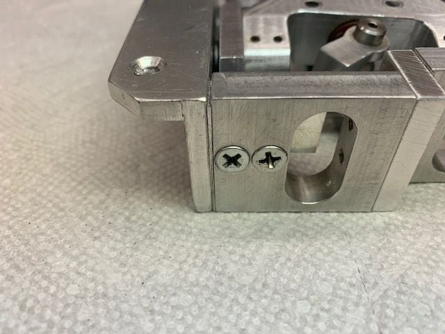
Malcolm, you are correct that the gear frame is assembled just with the screw threads and had no positioning dowels or pins anywhere.
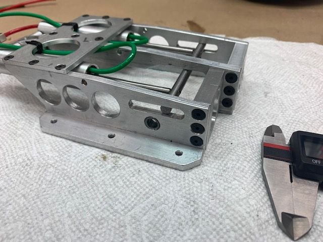
It is completely assembled with counter sunk flat head machine screws
It looks like the sides are from 90 degree angle aluminum and the rest is made of flat stock.
Malcolm, you are correct that the gear frame is assembled just with the screw threads and had no positioning dowels or pins anywhere.
It is completely assembled with counter sunk flat head machine screws
It looks like the sides are from 90 degree angle aluminum and the rest is made of flat stock.
02-11-2021, 07:01 PM
#888
Thread Starter
My Feedback: (20)
Shims in gear frame
Before I read Malcolm's posts I started checking the size of the bushing holes. A .250" drill bit fit right in the holes and appeared to be straight in both sides
Both bushing holes measured at .250"
Other side...
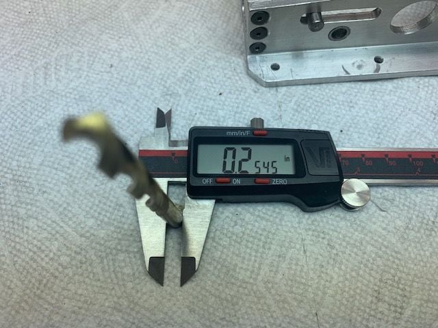
The next size up bit I had was a letter size F that measured .2545"
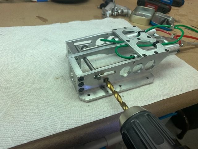
The bit was not long enough to go through the entire frame so I drilled from both sides by hand. I reassembled the gear and there was no change. It was still binding.
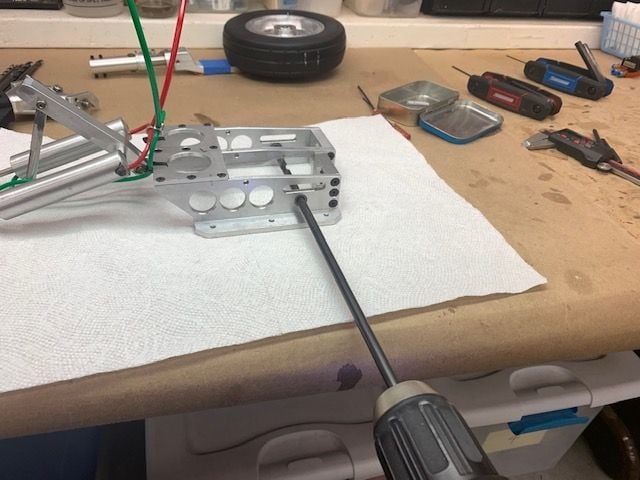
The next size up I had was 17/64". I had a 12" bit so I drilled it all the way through. Guess what. Still no change. You could feel the pivot start to bind as the side screws were tightened on the frame. I then realized it probably was not the bushing that was the problem. I went back to the thread to re-read what Thomas posted bout the size of the bit and that is when I saw Malcolm's post. He had it figured out exactly.
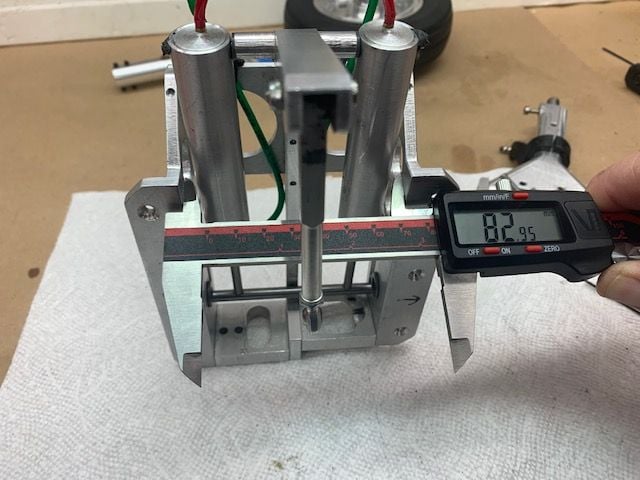
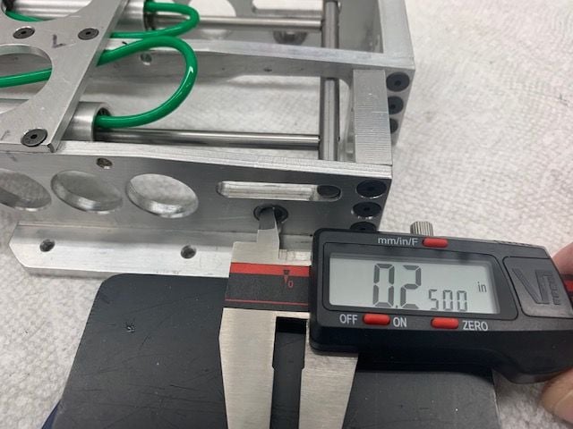
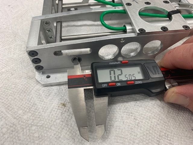
I then measured the inside top of the frame

Then the inside bottom. And yep they were different. So I started working with different shims. I found if I shimmed the outside screws it would free up the binding and the gear pivot worked freely.
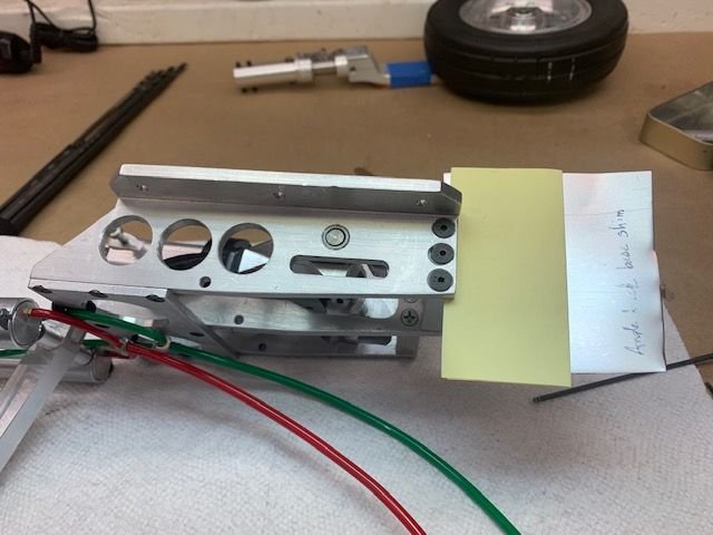
Here is a metal shim stock plus two layers of paper. This was about .028" total. I tried two layers of shim stock at .030" and it worked ok.
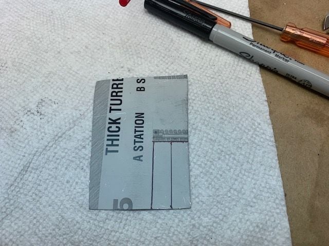
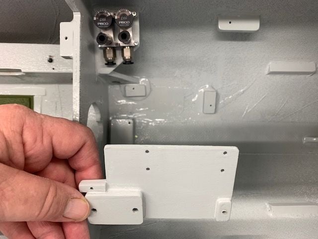
Next I cut two shims to fit.
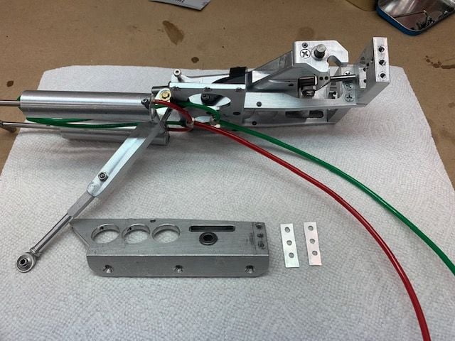
Two shims cut, flattened, drilled, and ready to install
The shims assembled inside the frame spread the outside edge about .030". This made the pivot work freely. Now the main drag is the air cylinder pistons. I only wish I had read Malcolm's post before I drilled out the bushing but it still seems to work OK. We will see if it makes difference after I get some taxi testing done.
I reassembled the gear and wing and tested again. It works ok now. I wish the left main gear it hit the up lock harder but I think it will work ok. Thanks guys for the tips. Made a little more progress today.
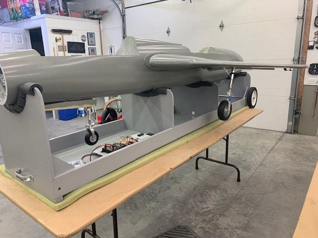
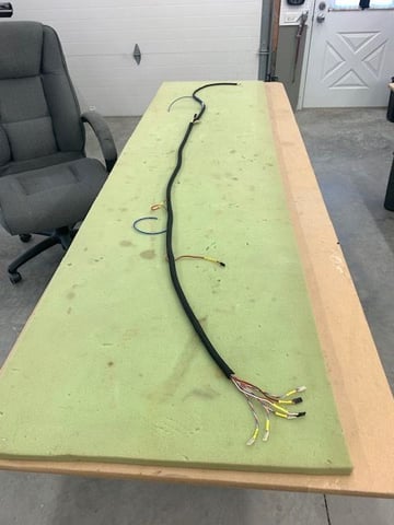
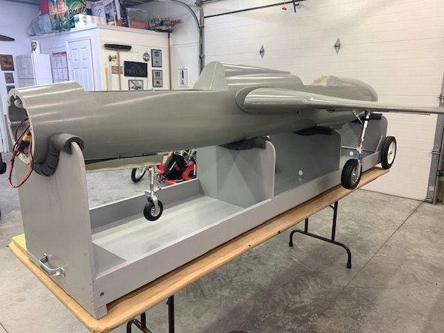
New transport mode with stabs off. I inserted the two Actobotics tubes inside the control horns to keep them from flopping around inside the fuse.
Have to go on a weekend trip to pay some RC domestic dues so no shop time for a few days. Thanks for all the help and encouragement.
Gary
Before I read Malcolm's posts I started checking the size of the bushing holes. A .250" drill bit fit right in the holes and appeared to be straight in both sides
Both bushing holes measured at .250"
Other side...
The next size up bit I had was a letter size F that measured .2545"
The bit was not long enough to go through the entire frame so I drilled from both sides by hand. I reassembled the gear and there was no change. It was still binding.
The next size up I had was 17/64". I had a 12" bit so I drilled it all the way through. Guess what. Still no change. You could feel the pivot start to bind as the side screws were tightened on the frame. I then realized it probably was not the bushing that was the problem. I went back to the thread to re-read what Thomas posted bout the size of the bit and that is when I saw Malcolm's post. He had it figured out exactly.
I then measured the inside top of the frame
Then the inside bottom. And yep they were different. So I started working with different shims. I found if I shimmed the outside screws it would free up the binding and the gear pivot worked freely.
Here is a metal shim stock plus two layers of paper. This was about .028" total. I tried two layers of shim stock at .030" and it worked ok.
Next I cut two shims to fit.
Two shims cut, flattened, drilled, and ready to install
The shims assembled inside the frame spread the outside edge about .030". This made the pivot work freely. Now the main drag is the air cylinder pistons. I only wish I had read Malcolm's post before I drilled out the bushing but it still seems to work OK. We will see if it makes difference after I get some taxi testing done.
I reassembled the gear and wing and tested again. It works ok now. I wish the left main gear it hit the up lock harder but I think it will work ok. Thanks guys for the tips. Made a little more progress today.
New transport mode with stabs off. I inserted the two Actobotics tubes inside the control horns to keep them from flopping around inside the fuse.
Have to go on a weekend trip to pay some RC domestic dues so no shop time for a few days. Thanks for all the help and encouragement.
Gary
Last edited by Viper1GJ; 02-11-2021 at 07:09 PM.
02-15-2021, 05:47 PM
#890
Thread Starter
My Feedback: (20)
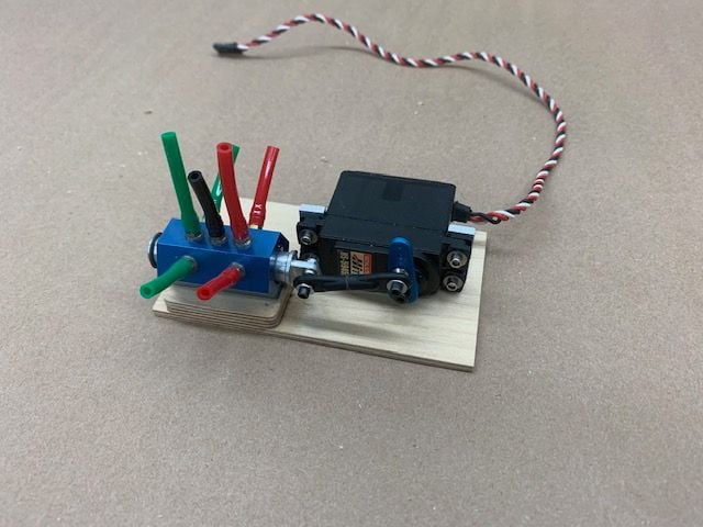
JMP servo operated air valve
Not much shop time since last post. Next step is to get new air valve mounted and working

Got the 4mm nipple JMP air valve mounted and connected to servo. Next is to get this assembly to fit in and around all the rest of the stuff in the air compartment. I will have to take out the electric valve mount and reroute air lines for the new valve and get the system tested.
Not much shop time since last post. Next step is to get new air valve mounted and working
Got the 4mm nipple JMP air valve mounted and connected to servo. Next is to get this assembly to fit in and around all the rest of the stuff in the air compartment. I will have to take out the electric valve mount and reroute air lines for the new valve and get the system tested.
02-16-2021, 06:23 PM
#892
Thread Starter
My Feedback: (20)
Thanks Jamie.
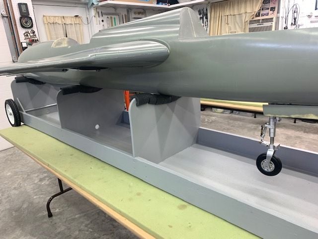
Getting the landing gear system to work is kicking my butt. I put it off till last because I knew it would cause problems so now I have to deal with them. Fortunately Larry is helping me by working on a system to pull the gear strut into the wheel well with some magnets. This will help reduce the droop down below the wing skin when in the gear well. I will have to have some machining help to keep the lower strut aligned to the upper strut. The set screws I tried are not working.
Once I get this sorted out I can then figure out how to mount the gear doors and run brake and rpm lines. Eventually I will glue on the vertical tail. Keeping that till last so I don't have to deal with it when moving the fuse around for other stuff first.
Not much shop time this week. Trying to get camper going after winter for fly in this weekend and building a doll house for granddaughter. F-105 just sits there and laughs at me!
Gary
 02-16-2021, 08:07 PM
#894
Gary,
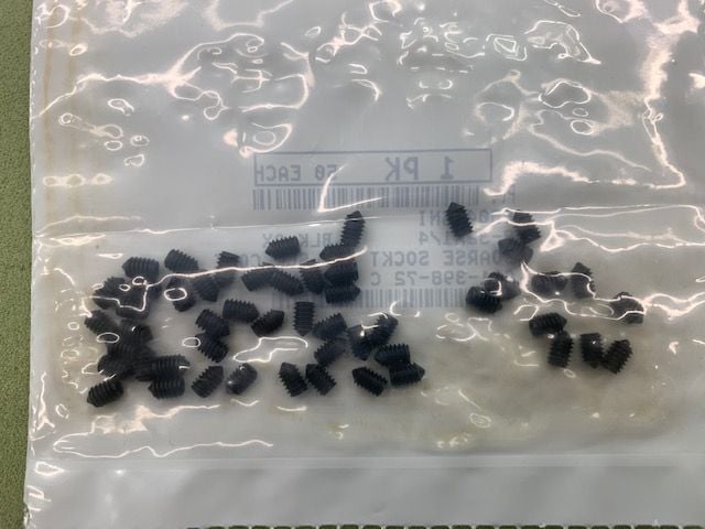
for your strut dilemna, have you looked into the high-hold �cone point� setscrews? They have either a 90* or 118* �point� on the end of them that when set into a drilled recess on the receiving part, creates a very secure method of retention that is resistent to twisting, much more so than the ground flat spot and conventional blunt nosed setscrew.
Thomas
02-17-2021, 05:27 PM
#895
Thread Starter
My Feedback: (20)
Gary, for your strut dilemna, have you looked into the high-hold “cone point” setscrews? They have either a 90* or 118* “point” on the end of them that when set into a drilled recess on the receiving part, creates a very secure method of retention that is resistent to twisting, much more so than the ground flat spot and conventional blunt nosed setscrew. Thomas
Thomas,
That sounds like a great idea! I already have the flats ground on the titanium upper strut pins. The point might just grab enough to hold. Do you have a source for getting the cone point set screws and which ones would you recommend, 90 or 118?
Many thanks,
Gary
P.S. Just did some searching and have more questions. Should I look for a steel or a titanium cone point set screw. I think I see that steel is harder so would it be the best screw material or not? MacMaster has screws, looks like the 118* is for the smaller diameter screws like I need. Any set screw engineers out there???
Last edited by Viper1GJ; 02-17-2021 at 05:59 PM.
02-20-2021, 12:34 PM
#896
Thread Starter
My Feedback: (20)
Installing JMP air valve
I got some cone point set screws ordered for the landing gear. I hope this will solve the problem. If they do I can proceed to mounting the main gear doors and routing the brake lines and MRPM sensor wire.
Next trick was to get this installed into the fuse and refit all the plumbing

After some cutting, sanding, gluing, and drilling I got it this far and ready to epoxy the mounts on the fuse
Overnight the epoxy and paint cured and ready to assemble
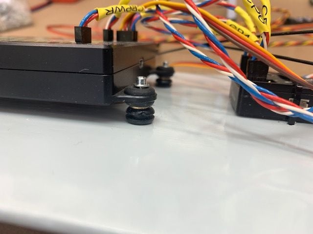
I had to remove both servo cables to get more wire to the front where everything plugs into the CB400. It was a pain to take it all out and then put it all back in but I made a few improvements on the 2nd install
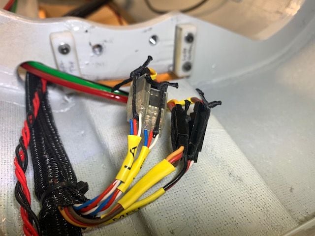
All the servo connectors to the MPI multi wing plug secured.
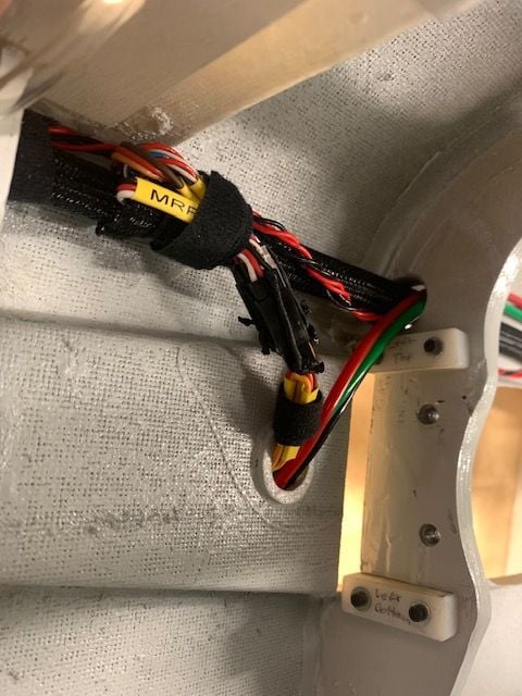
Thin Velcro one wrap holds the connectors up and out of the way of the wing mounting bolt holes. This was a problem on the first install as the wires were blocking the upper bolt hole
All the air plumbing reconnected to the air valve and ready to test. Oh, not so fast... now the fuel tray won't fit. The air lines on top of the valve are too tall. I think I can trim them down some but not sure if it will be enough. It's always something...Time for an attitude readjustment!
I got some cone point set screws ordered for the landing gear. I hope this will solve the problem. If they do I can proceed to mounting the main gear doors and routing the brake lines and MRPM sensor wire.
Next trick was to get this installed into the fuse and refit all the plumbing
After some cutting, sanding, gluing, and drilling I got it this far and ready to epoxy the mounts on the fuse
Overnight the epoxy and paint cured and ready to assemble
I had to remove both servo cables to get more wire to the front where everything plugs into the CB400. It was a pain to take it all out and then put it all back in but I made a few improvements on the 2nd install
All the servo connectors to the MPI multi wing plug secured.
Thin Velcro one wrap holds the connectors up and out of the way of the wing mounting bolt holes. This was a problem on the first install as the wires were blocking the upper bolt hole
All the air plumbing reconnected to the air valve and ready to test. Oh, not so fast... now the fuel tray won't fit. The air lines on top of the valve are too tall. I think I can trim them down some but not sure if it will be enough. It's always something...Time for an attitude readjustment!
Last edited by Viper1GJ; 02-20-2021 at 12:39 PM.
02-21-2021, 05:15 PM
#897
Thread Starter
My Feedback: (20)
Replumbing air valve
 ne
ne
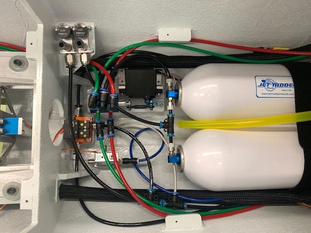
After some cutting and fitting I finally got the plumbing on the top of the JMP air valve to fit below the fuel tray by bending the air lines over to the right. Straight couplers were used for all the connections.
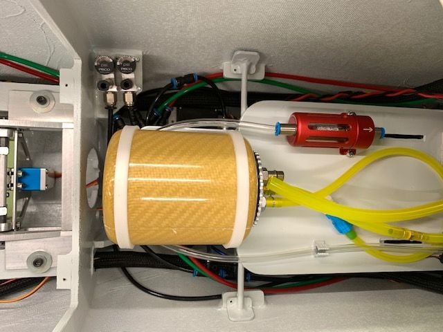
Fuel tray now fits on the mounting tabs. This iteration developed because I was trying to get the air trap tank as far forward as possible but it would not fit under the cockpit tray. So I lowered it and it fit ok with the electronic valve but with the new bigger mechanical valve it was too low. All is well now and ready for more testing of the gear system using internal air.
ne After some cutting and fitting I finally got the plumbing on the top of the JMP air valve to fit below the fuel tray by bending the air lines over to the right. Straight couplers were used for all the connections.
Fuel tray now fits on the mounting tabs. This iteration developed because I was trying to get the air trap tank as far forward as possible but it would not fit under the cockpit tray. So I lowered it and it fit ok with the electronic valve but with the new bigger mechanical valve it was too low. All is well now and ready for more testing of the gear system using internal air.
02-22-2021, 06:00 PM
#898
Thread Starter
My Feedback: (20)
Another gear test...
Did a full dress rehearsal today. Got the jet on the cradle. Mounted the fuel tray and made all connections to ECU and fuel. I mounted the RC tray and ran all connections in final install positions except for receiver antennas. It is a real PIA to get all the wires run up to the CB400 but I finally got it all in. I did a full radio, ECU, turbine, and sensors test. Everything worked. All flight controls worked, gear doors, Mspeed and Mrpm sensors, drag chute and retract valve servos worked ok. It was time to put in air and test the gear. All three gear extended as I added the air. At 100psi I retracted the gear and BAM! The RC tray and CB400 jumped off the mounts. Well that was the end of the test.
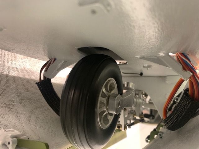
The bottom of the RC tray has a relief hole just above the wheel. I assumed I did not have enough clearance between the bottom of the CB400 and the nose wheel and had not accounted for the slack in the nose strut from slop in the up lock. I assumed that the wheel was hitting the bottom of the CB400 as it retracted very fast and hard.
So I pulled out the RC tray and all of those wires. I lifted the CB400 with rubber grommets to make some additional clearance between the nose wheel and the bottom of the CB400. I reinstalled the RC tray but only connected the gear valve servo. Retested the gear again and observed the hard retraction again. The wheel did not hit the RC tray but still shook it hard. Just the up swing of the strut hitting the stops was shaking the RC tray. Next I installed a flow control fitting on the up line and adjusted the pressure in the up line. Problem solved. Yea!
However,,, as I testing the gear and got the nose gear tuned in for a soft retract cycle I noticed that the right main gear STOPPED extending. WHAT NOW! The right gear always worked...till now. I got under it and you can see the slider bar moving on one side and hanging on the other side. Just like the nose gear did at first. I was tired, fried, and frustrated. UGGGH! Time to quit.
On a good note the cone tipped set screws for the main gear struts came in. I'll try again tomorrow.
Did a full dress rehearsal today. Got the jet on the cradle. Mounted the fuel tray and made all connections to ECU and fuel. I mounted the RC tray and ran all connections in final install positions except for receiver antennas. It is a real PIA to get all the wires run up to the CB400 but I finally got it all in. I did a full radio, ECU, turbine, and sensors test. Everything worked. All flight controls worked, gear doors, Mspeed and Mrpm sensors, drag chute and retract valve servos worked ok. It was time to put in air and test the gear. All three gear extended as I added the air. At 100psi I retracted the gear and BAM! The RC tray and CB400 jumped off the mounts. Well that was the end of the test.
The bottom of the RC tray has a relief hole just above the wheel. I assumed I did not have enough clearance between the bottom of the CB400 and the nose wheel and had not accounted for the slack in the nose strut from slop in the up lock. I assumed that the wheel was hitting the bottom of the CB400 as it retracted very fast and hard.
So I pulled out the RC tray and all of those wires. I lifted the CB400 with rubber grommets to make some additional clearance between the nose wheel and the bottom of the CB400. I reinstalled the RC tray but only connected the gear valve servo. Retested the gear again and observed the hard retraction again. The wheel did not hit the RC tray but still shook it hard. Just the up swing of the strut hitting the stops was shaking the RC tray. Next I installed a flow control fitting on the up line and adjusted the pressure in the up line. Problem solved. Yea!
However,,, as I testing the gear and got the nose gear tuned in for a soft retract cycle I noticed that the right main gear STOPPED extending. WHAT NOW! The right gear always worked...till now. I got under it and you can see the slider bar moving on one side and hanging on the other side. Just like the nose gear did at first. I was tired, fried, and frustrated. UGGGH! Time to quit.
On a good note the cone tipped set screws for the main gear struts came in. I'll try again tomorrow.
Last edited by Viper1GJ; 02-22-2021 at 06:05 PM.
02-22-2021, 06:53 PM
#899
I feel your frustration Gary! Atleast your still making progress, however slow it may be.
its amazing how much of a difference those hi-flow valves make on the retraction violence of the gear. I ripped the temporary attachment screws out of the rails i had on my first test. Lol
its amazing how much of a difference those hi-flow valves make on the retraction violence of the gear. I ripped the temporary attachment screws out of the rails i had on my first test. Lol
02-23-2021, 07:00 PM
#900
Thread Starter
My Feedback: (20)
I took the right wing off again and removed the right main gear. It appeared that the slider bar was hanging up on one side as did the nose gear. It looks like the weight of the wheel and strut is pressing more on one side of the up lock cam than the other. There are some marks on the side that hangs that are not on the other side. I may try to sand and polish that surface a little like I did to the nose gear and see if I can get that cylinder to pull together with the other side.
The cone point set screws show promise with the initial sets. I will have to see when I finally get the gear working.
Short week in the shop. Packing the camper and going to the Flying Tigers Chili Cook Off and Fly In on Thursday. The saga continues...
Gary
The cone point set screws show promise with the initial sets. I will have to see when I finally get the gear working.
Short week in the shop. Packing the camper and going to the Flying Tigers Chili Cook Off and Fly In on Thursday. The saga continues...
Gary