


1/7 Scale Blackburn Buccaneer All Composite Scratch Build
 04-11-2020, 01:56 PM
#376


After previously deciding on a turbine mounting location in the center fuselage, I could work on finalizing the inlet ducting. On the full-size, the engine is directly in line with the inlets, but on the model, in order to clear the main gear I have had to shift the engine inboard and up a bit, so there is a slight off-set of the engine to the intake.
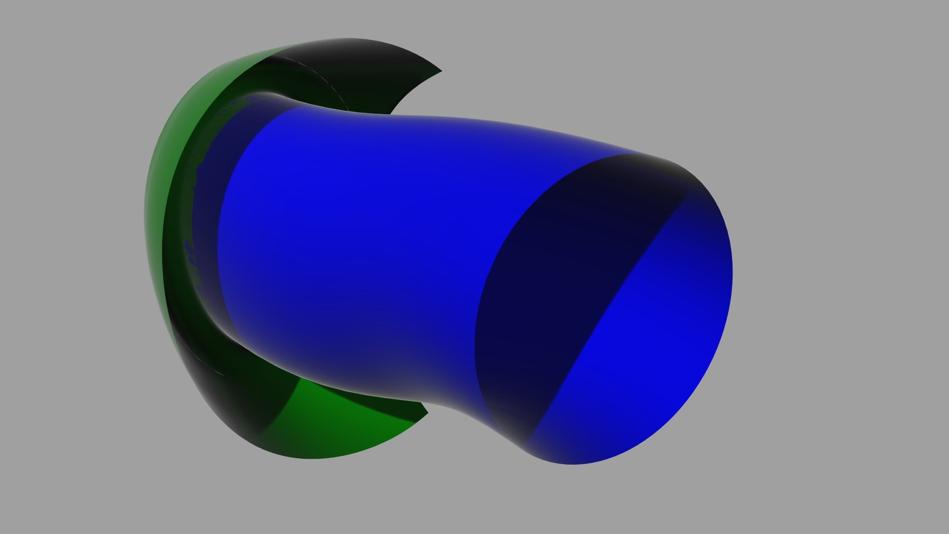
I created the inlet duct, transitioning from the ellipse shape at the front to a circle just in front of the engine. The duct then was formed between these with a gentle S curve to it in 2 dimensions. A quick area analysis along its length showed that it was of essentially constant area throughout.
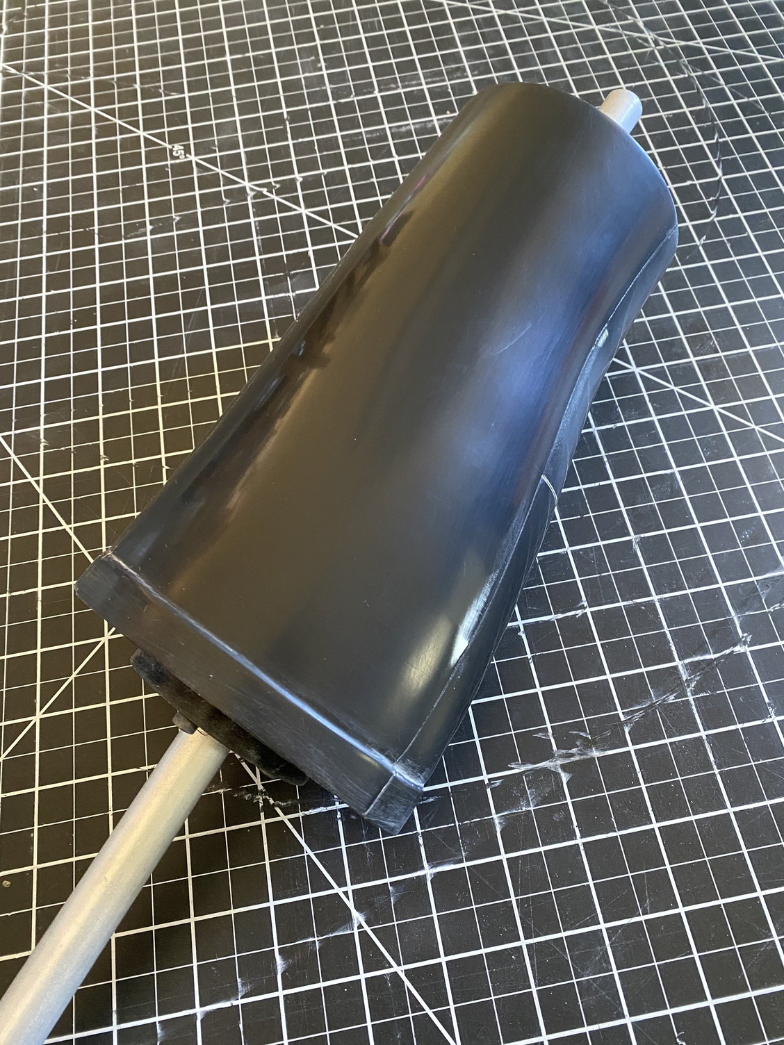
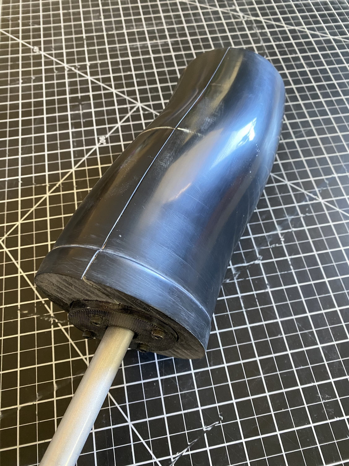
As the primary finished surface will be the inner surface of the duct the plug will also be the mold. In order to remove the mold, I split the plug into three pieces along its length, so that once the center piece is removed, the 2 out pieces can be withdrawn. This should avoid having to cut and re-join the duct. 2 end disks allow for the 3 parts to be bolted together. A hole down its length allows a support rod to hold it while I lay up the part.
The parts are on the printer, so I should be able to start working on finishing the first plug/ mold tomorrow. Some CAD views to help explain my concept.
Paul
I created the inlet duct, transitioning from the ellipse shape at the front to a circle just in front of the engine. The duct then was formed between these with a gentle S curve to it in 2 dimensions. A quick area analysis along its length showed that it was of essentially constant area throughout.
As the primary finished surface will be the inner surface of the duct the plug will also be the mold. In order to remove the mold, I split the plug into three pieces along its length, so that once the center piece is removed, the 2 out pieces can be withdrawn. This should avoid having to cut and re-join the duct. 2 end disks allow for the 3 parts to be bolted together. A hole down its length allows a support rod to hold it while I lay up the part.
The parts are on the printer, so I should be able to start working on finishing the first plug/ mold tomorrow. Some CAD views to help explain my concept.
Paul


 04-15-2020, 07:05 AM
#381
I don't post much but I'm loving your build! In addition to the sleeves above, you might consider some stretchy film for bagging material. much easier to get smooth for parts like this.
https://store.acpsales.com/products/...ch-bag-film-60
Red
https://store.acpsales.com/products/...ch-bag-film-60
Red
04-15-2020, 07:14 AM
#382
Thomas,
Thanks - those sleeves look very useful for this type of application.
Red,
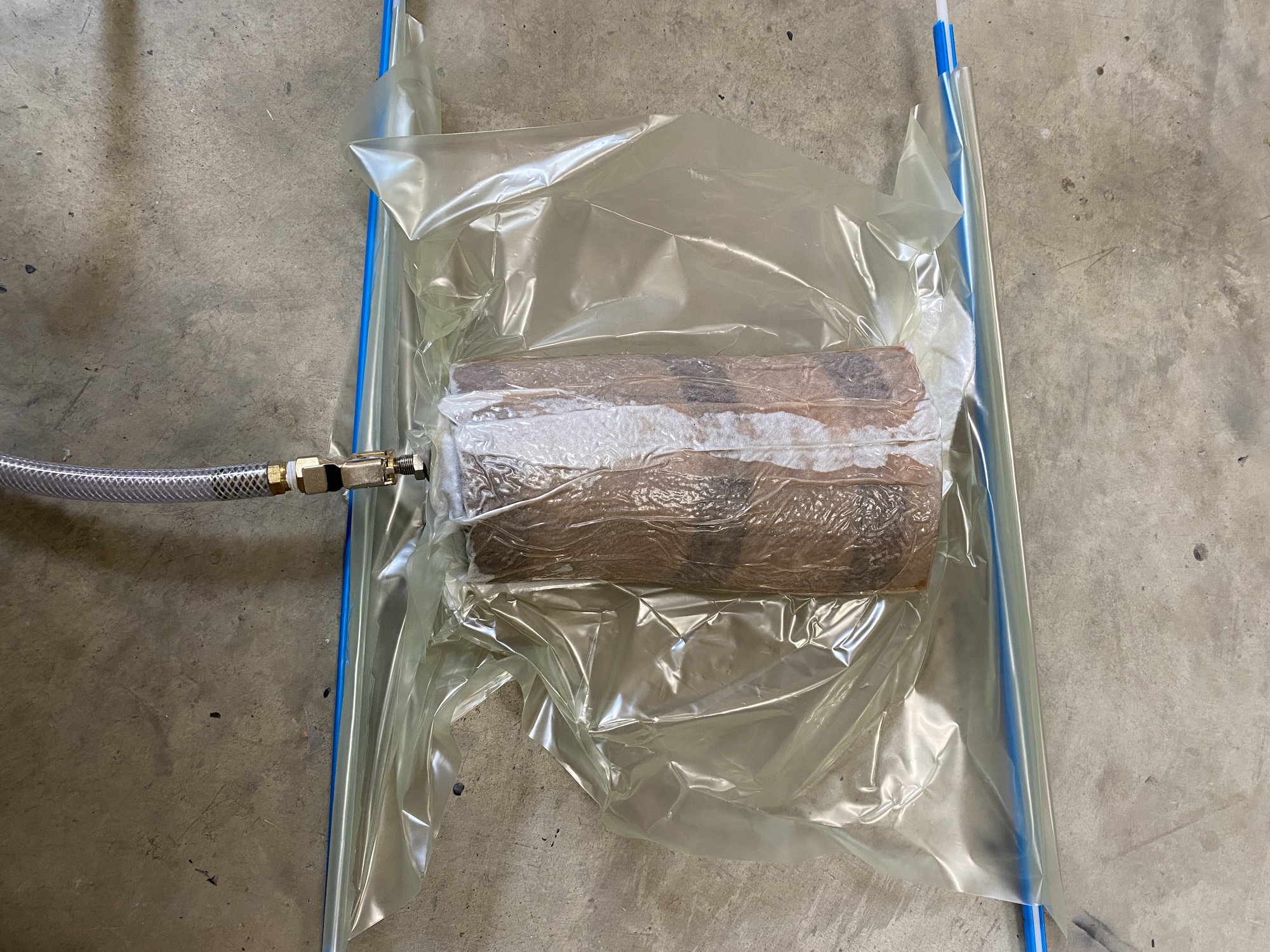
Those are exactly the bags that I'm using. I just did not pay enough attention to smoothing the bag out as I pulled the vacuum. Lesson learned. Will do better next time.
Paul
Thanks - those sleeves look very useful for this type of application.
Red,
Those are exactly the bags that I'm using. I just did not pay enough attention to smoothing the bag out as I pulled the vacuum. Lesson learned. Will do better next time.
Paul
The following users liked this post:
Lownverted (04-15-2020)
04-19-2020, 09:00 AM
#386
Progress on a couple of fronts.
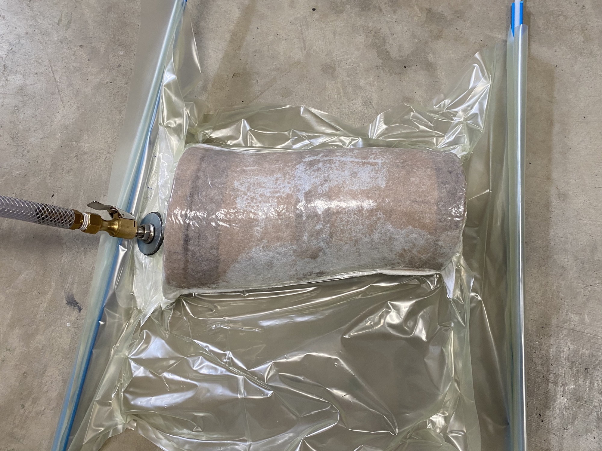
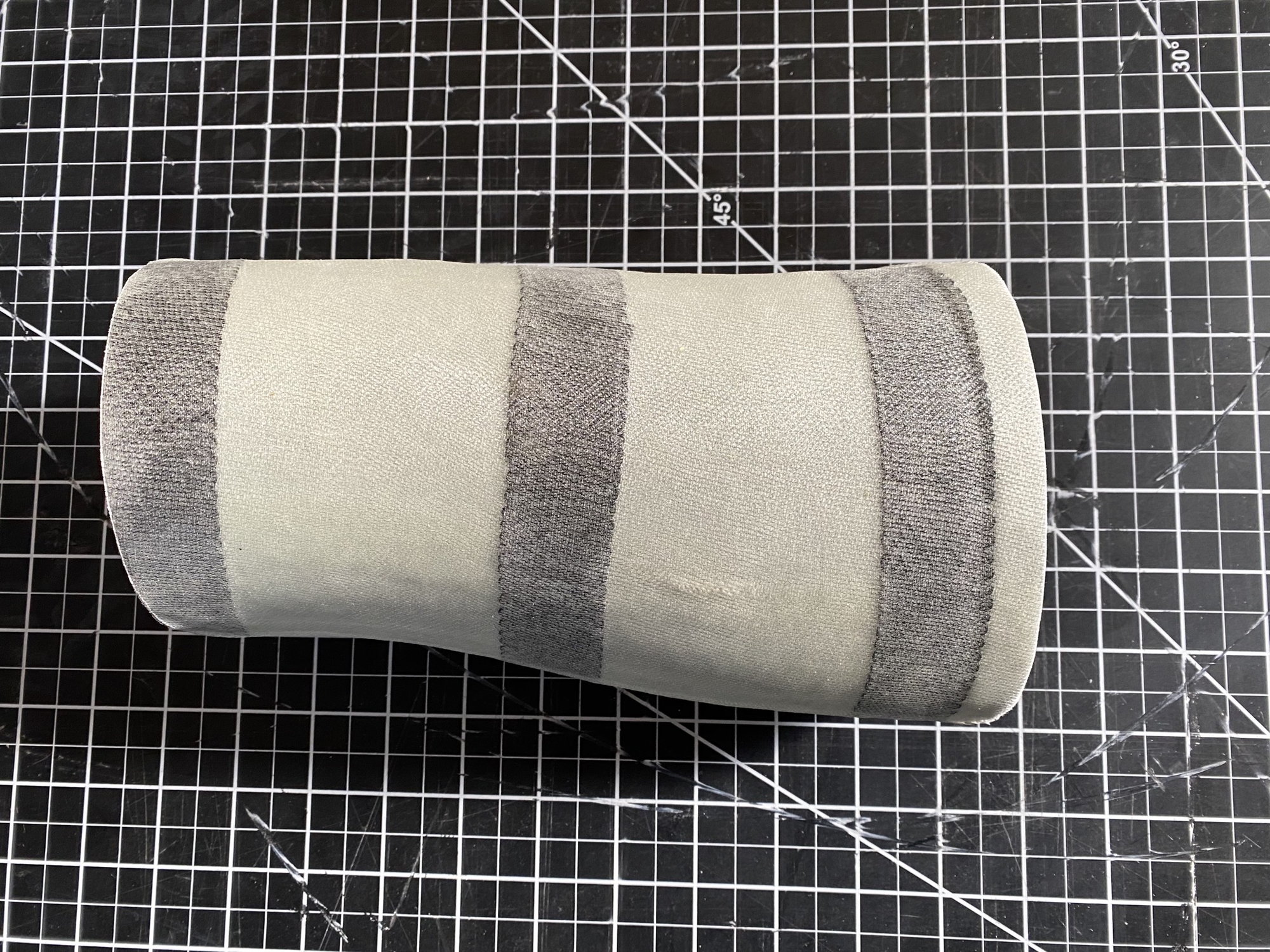
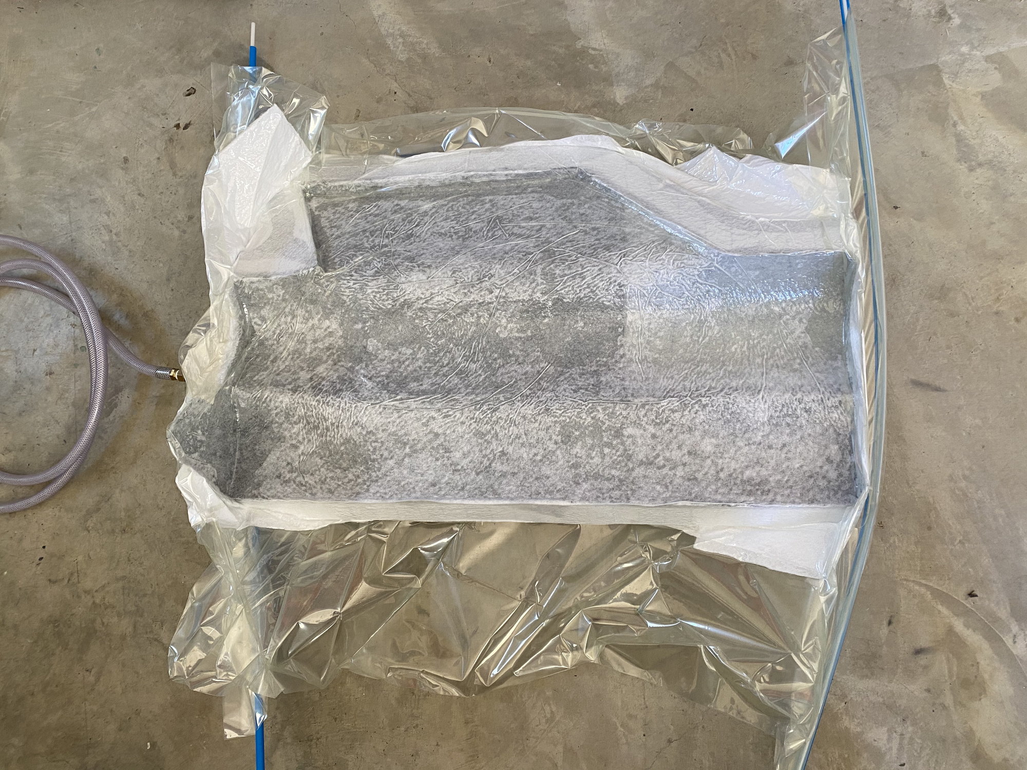
Second inlet duct done. Much better. I took the time to smooth out all the wrinkles in the vacuum bag as I sucked it down.
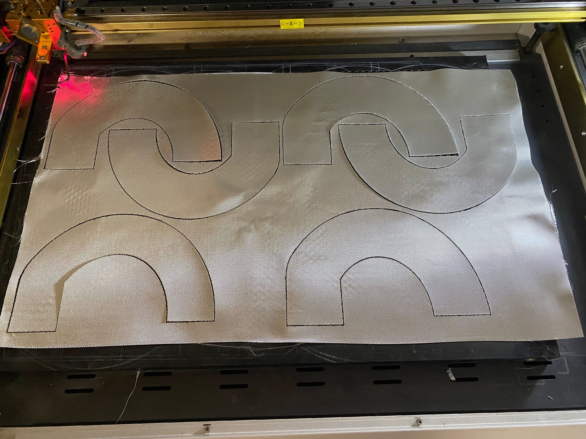
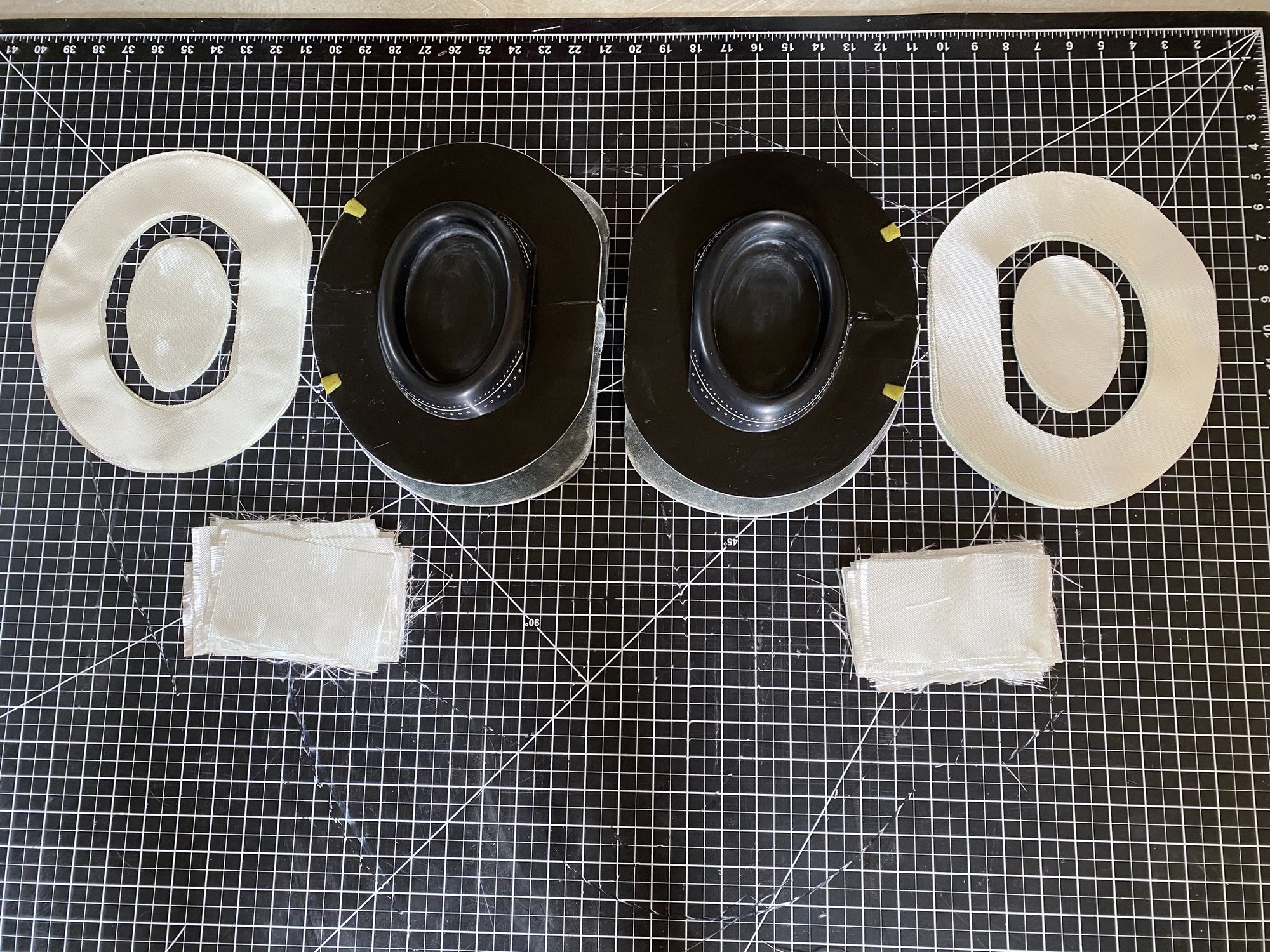
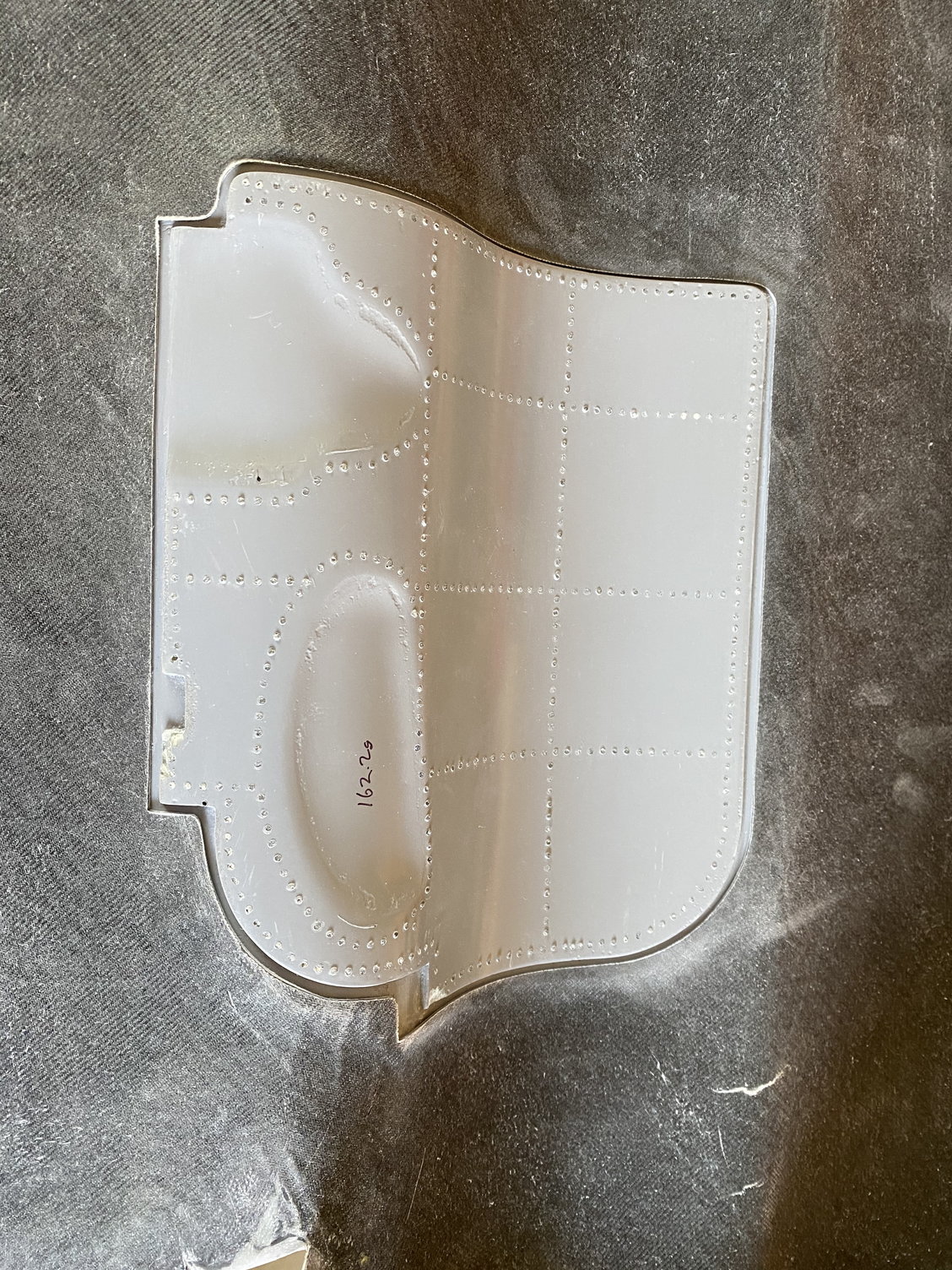
Both inlet plugs printed, sanded and glassed. They have also been trimmed, sanded again and painted with Duratec. Just waiting for final finish sanding and polishing. I tried Thomas's trick of laser cutting the glass for the oval insert and it worked perfectly and a drop in perfect fit.
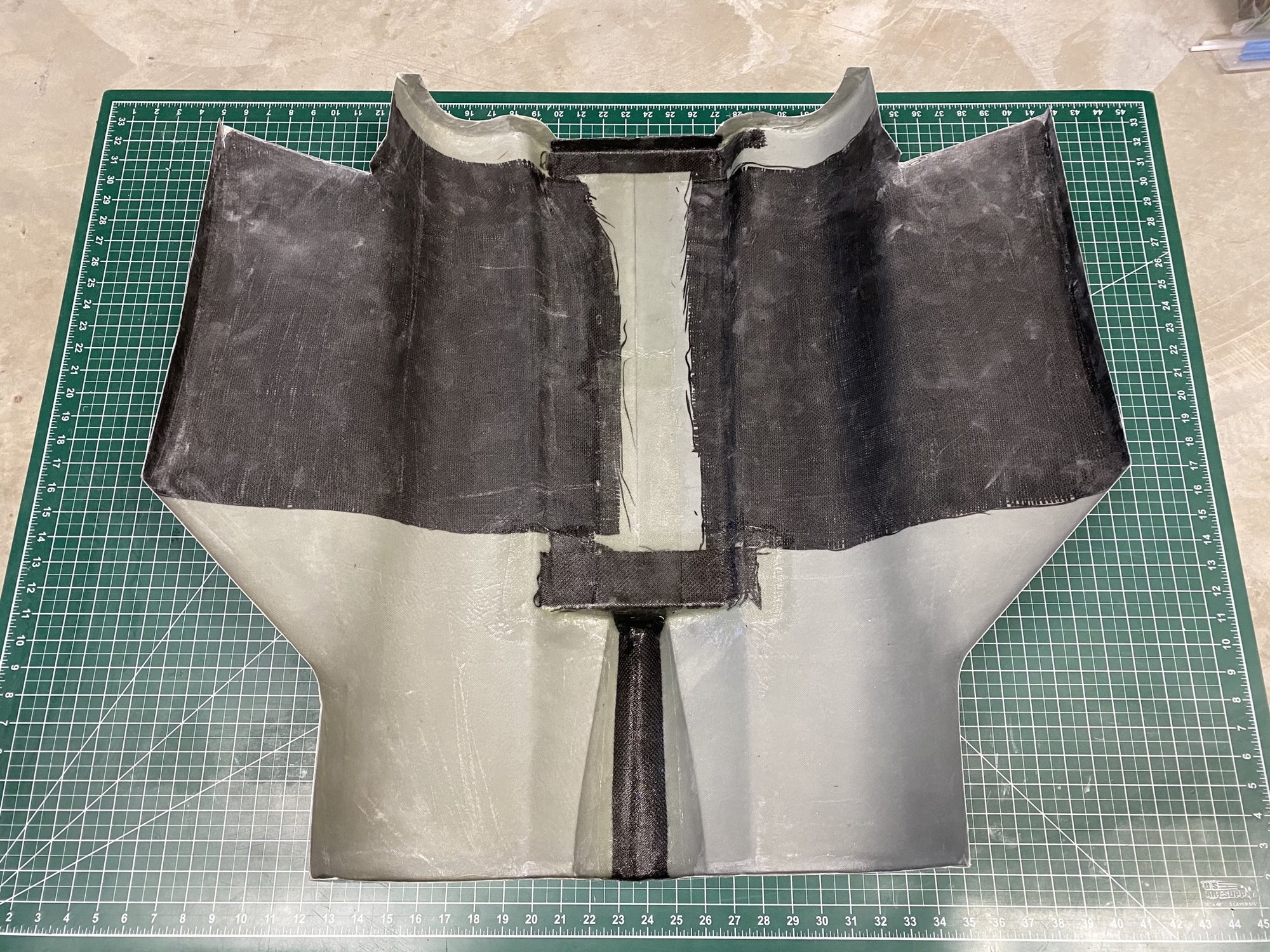
The first part of the center fuselage skins were laid up. Sprayed primer, followed by filling in the sharp corners before laying down a surface veil. Then the glass and carbon before vacuum bagging it.


Paul
Second inlet duct done. Much better. I took the time to smooth out all the wrinkles in the vacuum bag as I sucked it down.
Both inlet plugs printed, sanded and glassed. They have also been trimmed, sanded again and painted with Duratec. Just waiting for final finish sanding and polishing. I tried Thomas's trick of laser cutting the glass for the oval insert and it worked perfectly and a drop in perfect fit.
The first part of the center fuselage skins were laid up. Sprayed primer, followed by filling in the sharp corners before laying down a surface veil. Then the glass and carbon before vacuum bagging it.
Paul
 04-25-2020, 11:25 AM
#388
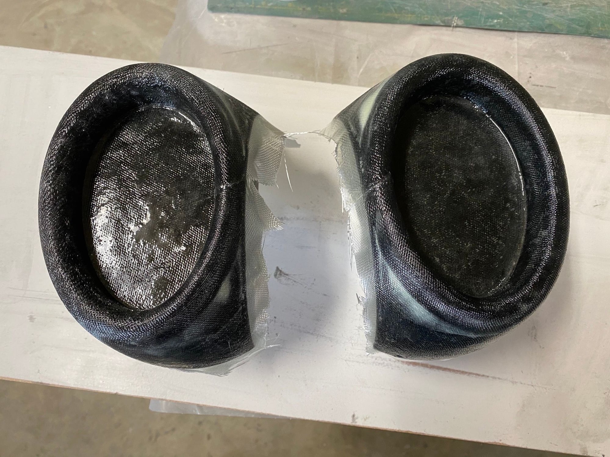
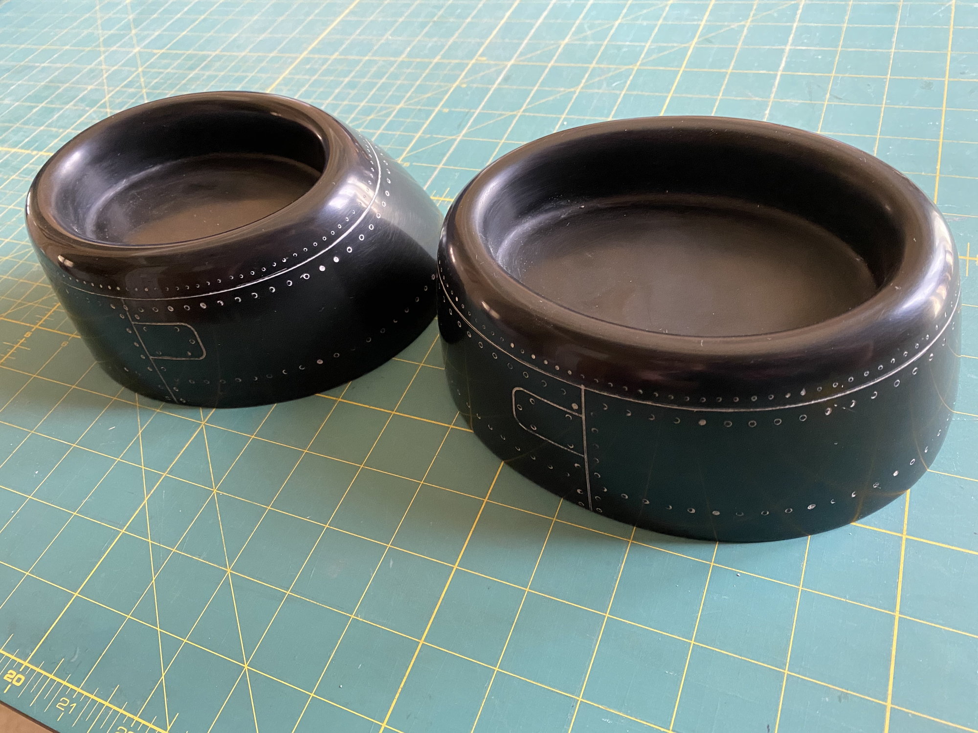
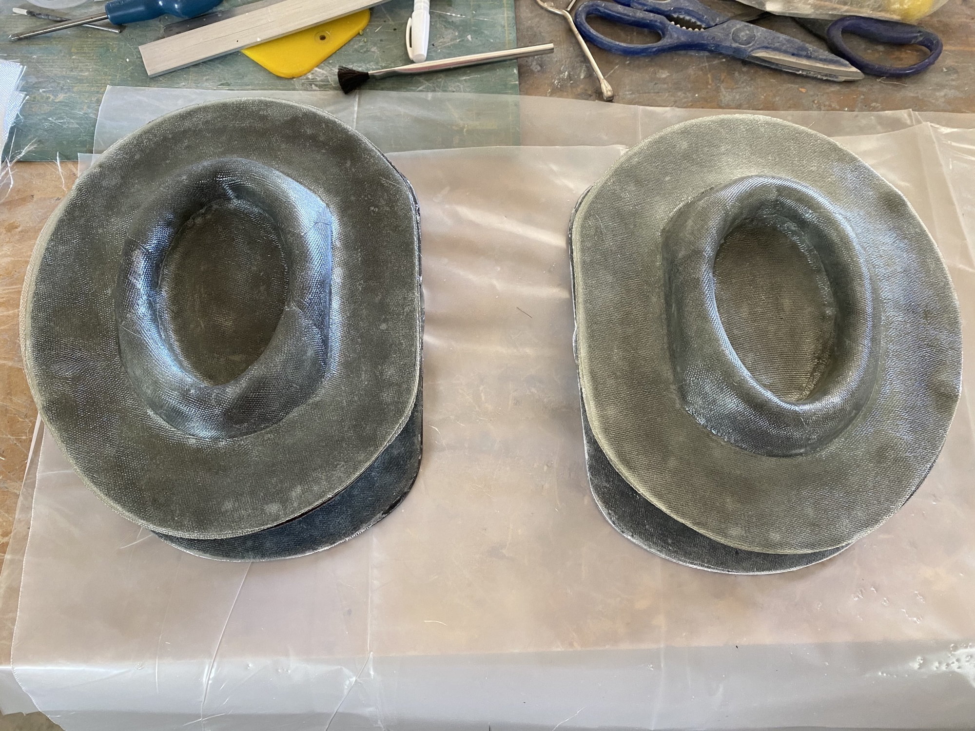
I completed the inlet molds. I used the laser cut glass cloth approach that Thomas (Invertmast) tried on this T-38, and it worked great. It resulted in a very neat and clean set of molds. No frayed edges to the glass and it holds its shape well as the laser fuses the cut glass edges.
For some reason these molds stuck and took a lot of brute force and multiple wedges to get apart. Some slight damage but luckily not on any critical surface and they can be cleaned up and polished to a perfectly usable condition. The plugs will need to be refinished if I ever need to remake the molds.
I have also laid up the second side of the center fuselage top skin.

Paul
For some reason these molds stuck and took a lot of brute force and multiple wedges to get apart. Some slight damage but luckily not on any critical surface and they can be cleaned up and polished to a perfectly usable condition. The plugs will need to be refinished if I ever need to remake the molds.
I have also laid up the second side of the center fuselage top skin.
Paul

 04-29-2020, 04:54 PM
#394
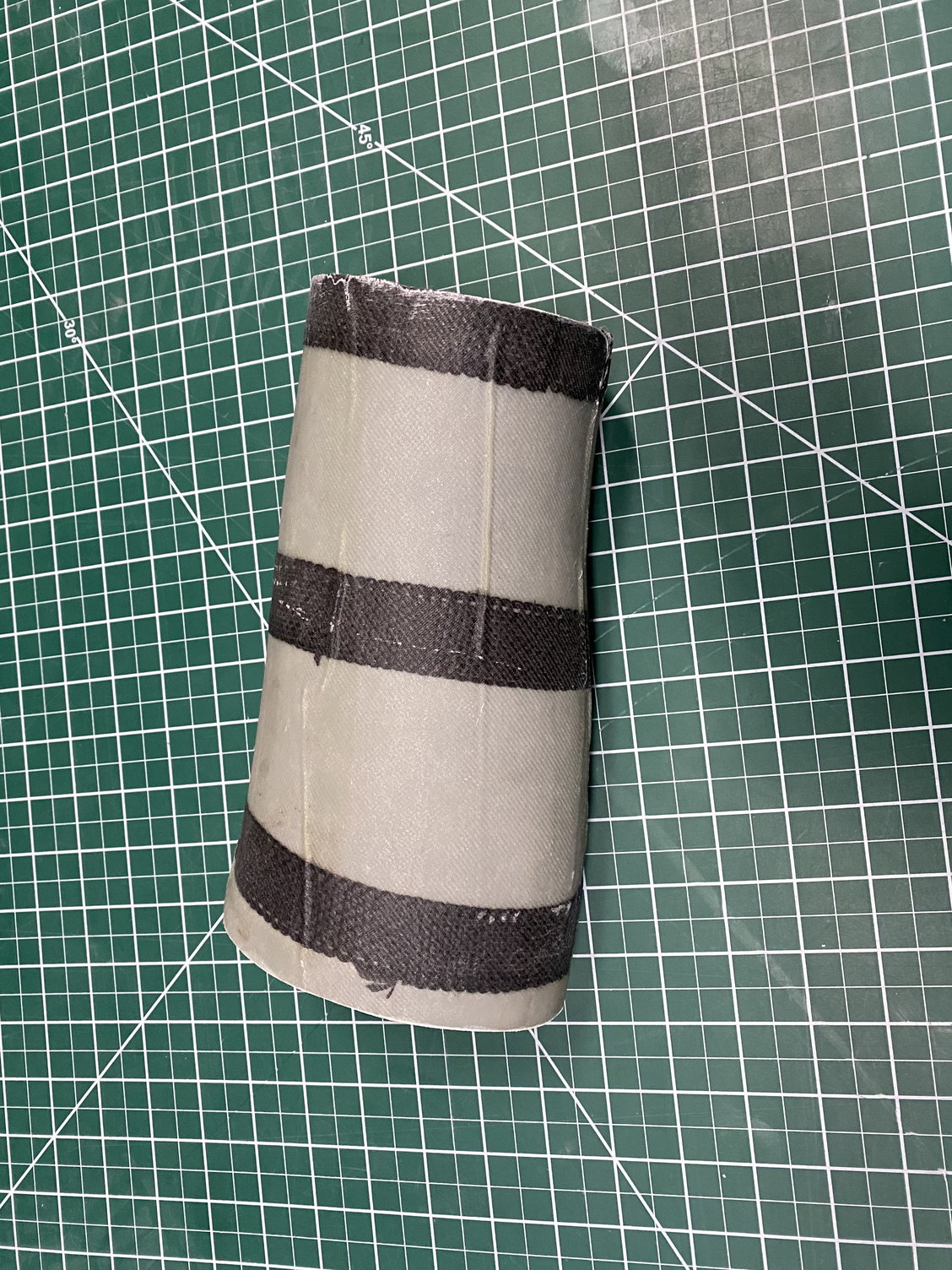
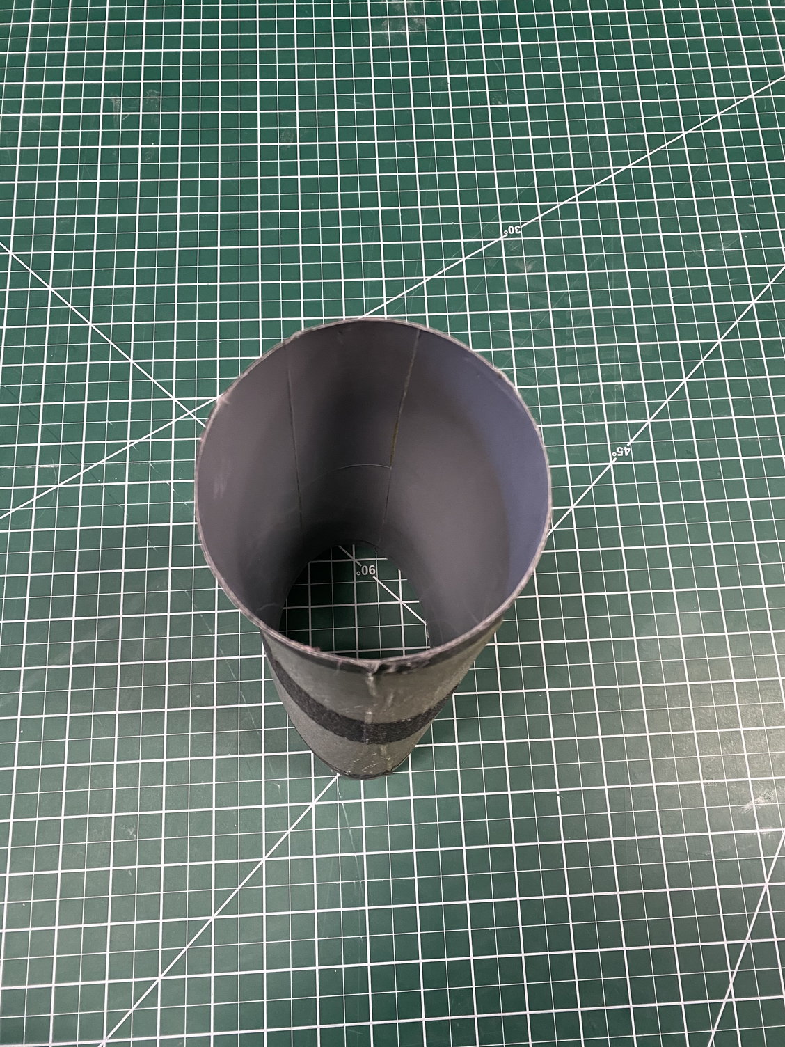
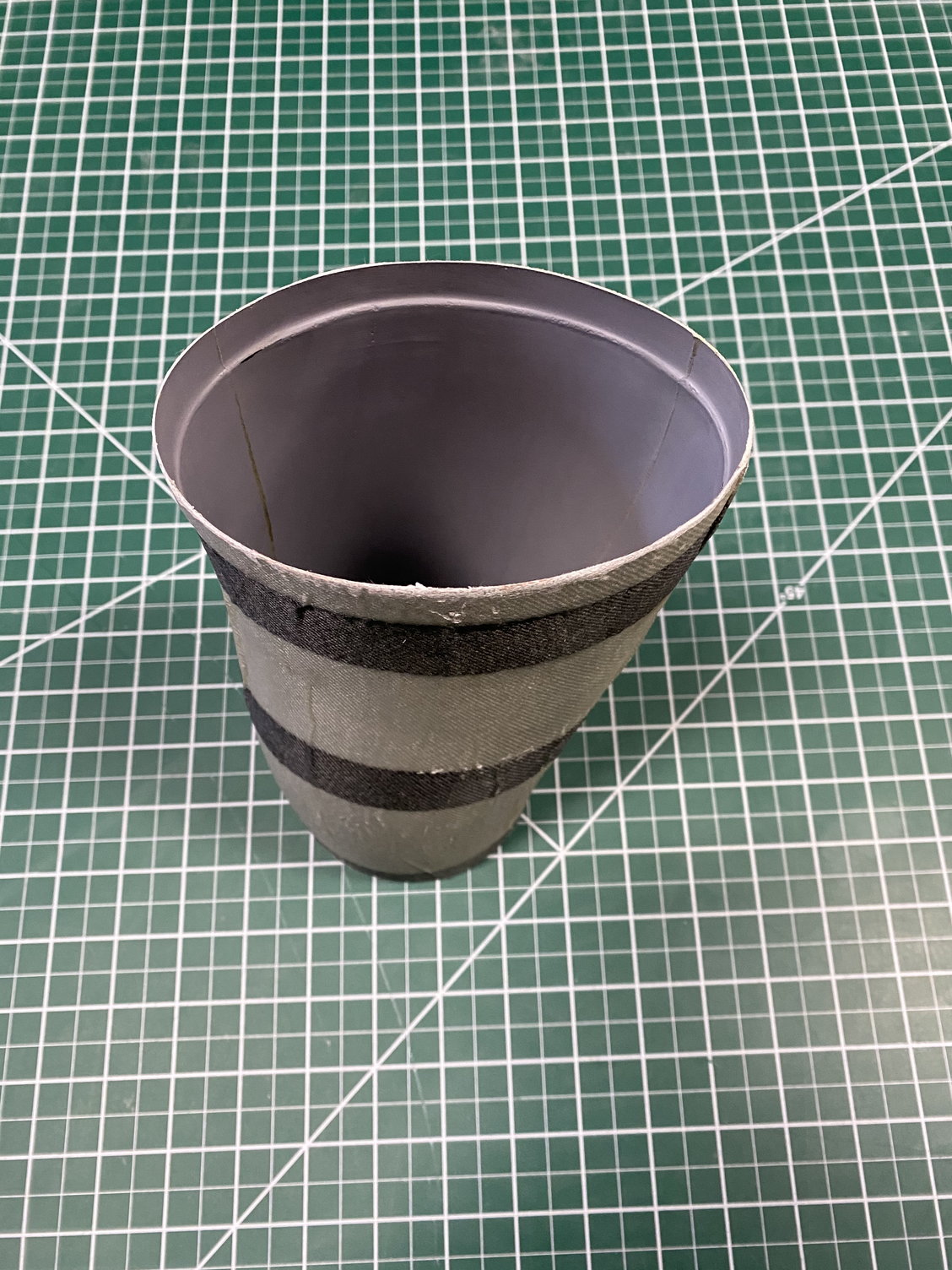
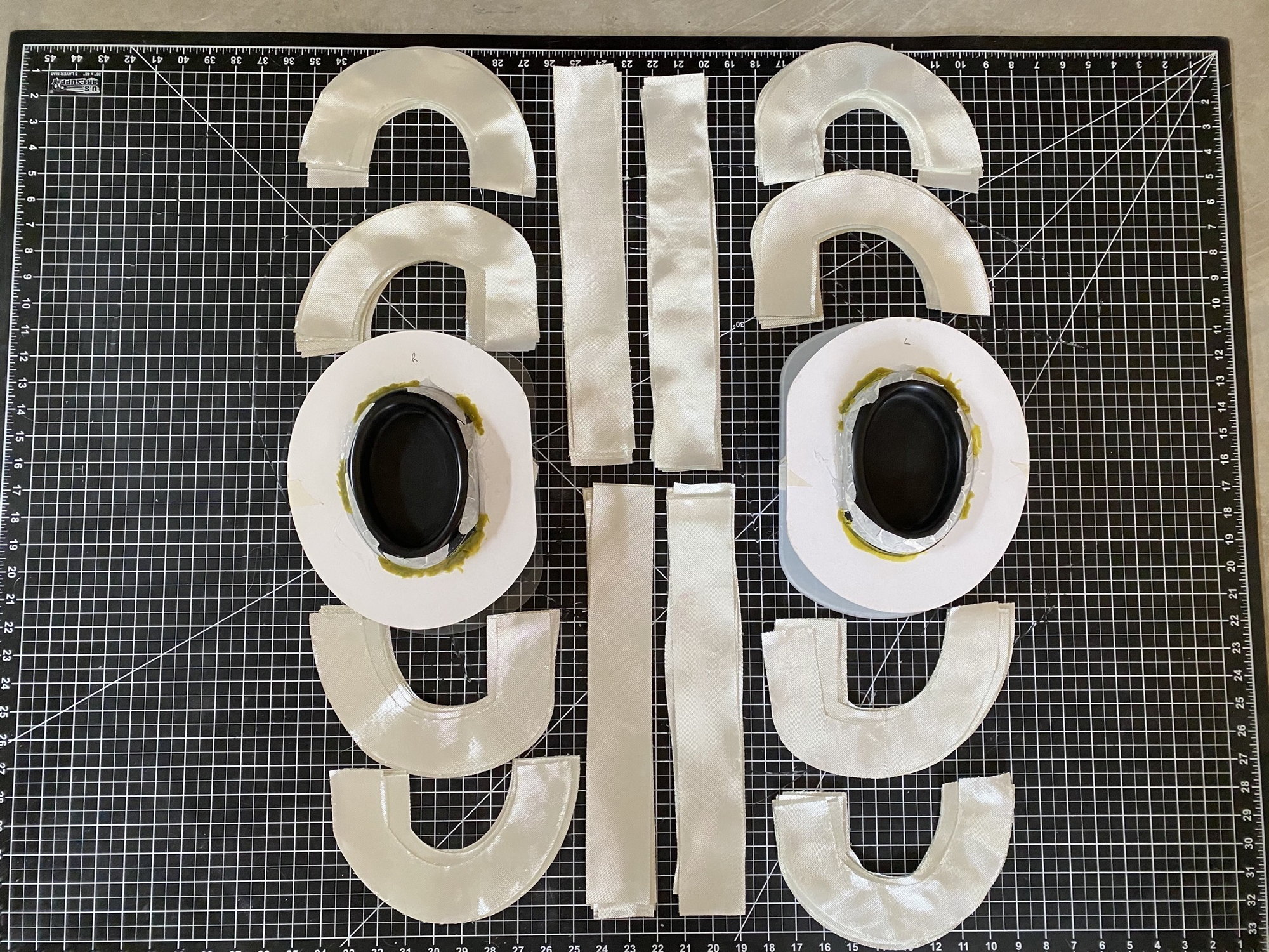
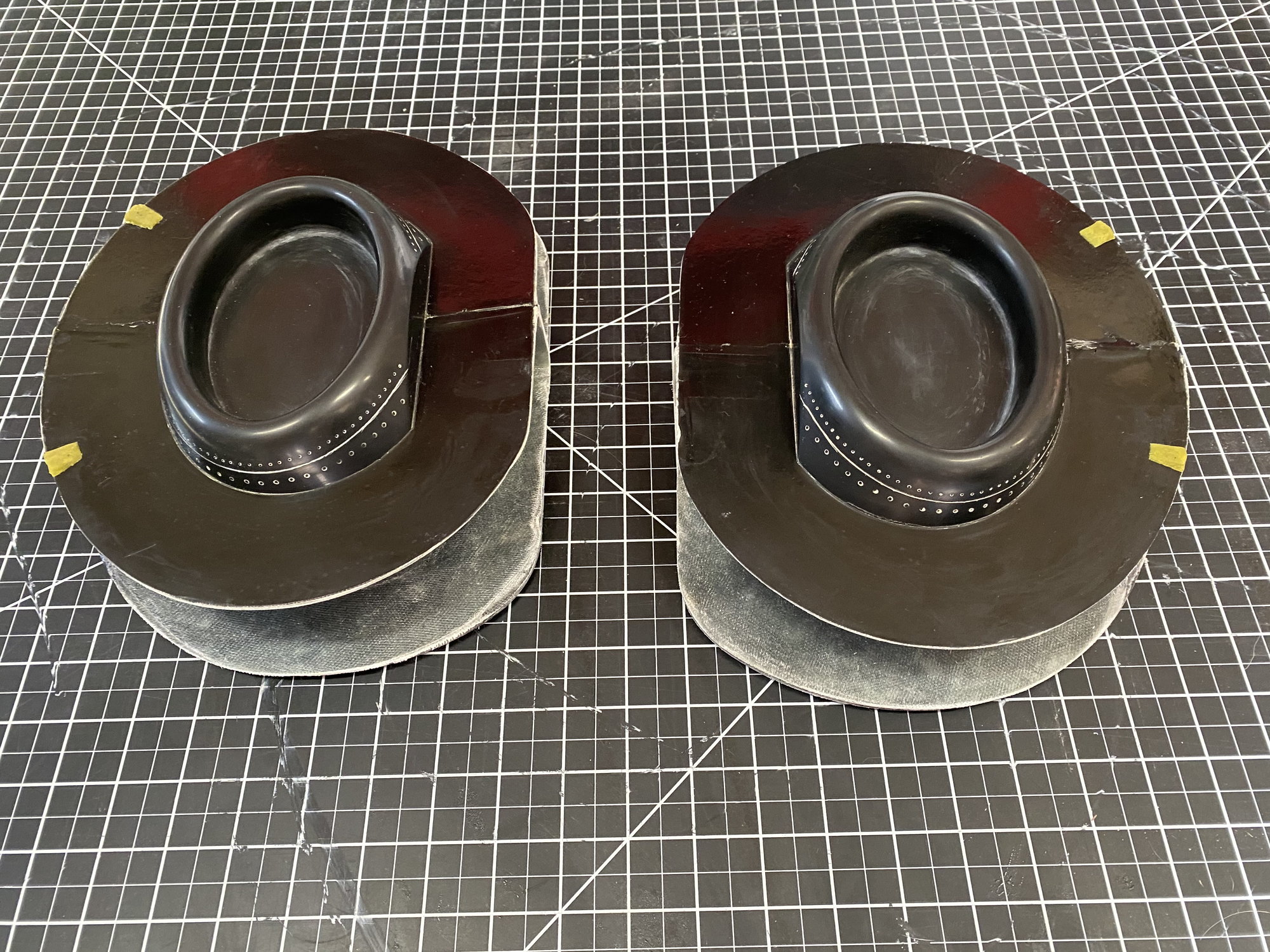
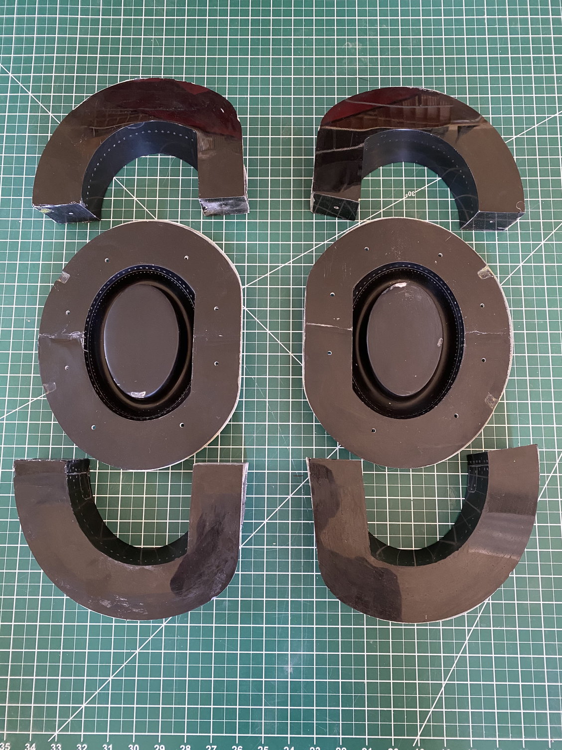
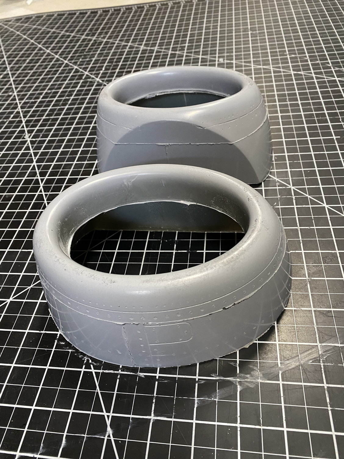
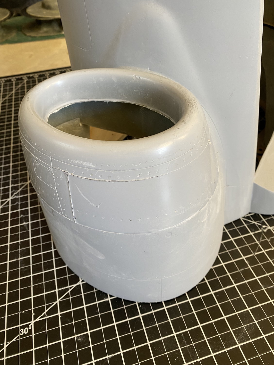
Didn't take long to layup the intakes. Given the shape I didn't vacuum bag these, just a simple wet hand layup.
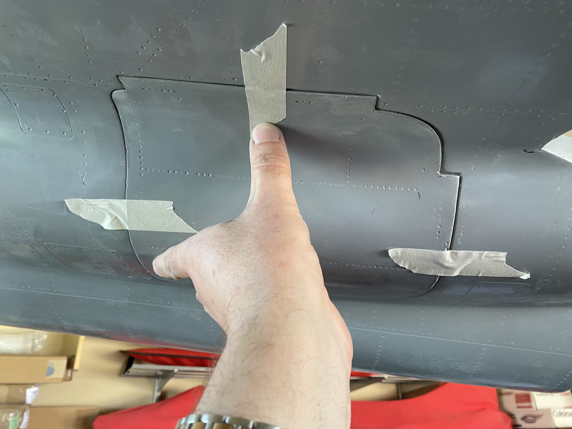
Only rough trimming so far and a quick trial fit to the front fuselage and to the inlet ducts, but they seem to fit fine to both.


Paul
Only rough trimming so far and a quick trial fit to the front fuselage and to the inlet ducts, but they seem to fit fine to both.
Paul
05-03-2020, 09:26 AM
#396
Thanks Thomas, but I'll pass. Corona virus and all that makes travel hard right now.....
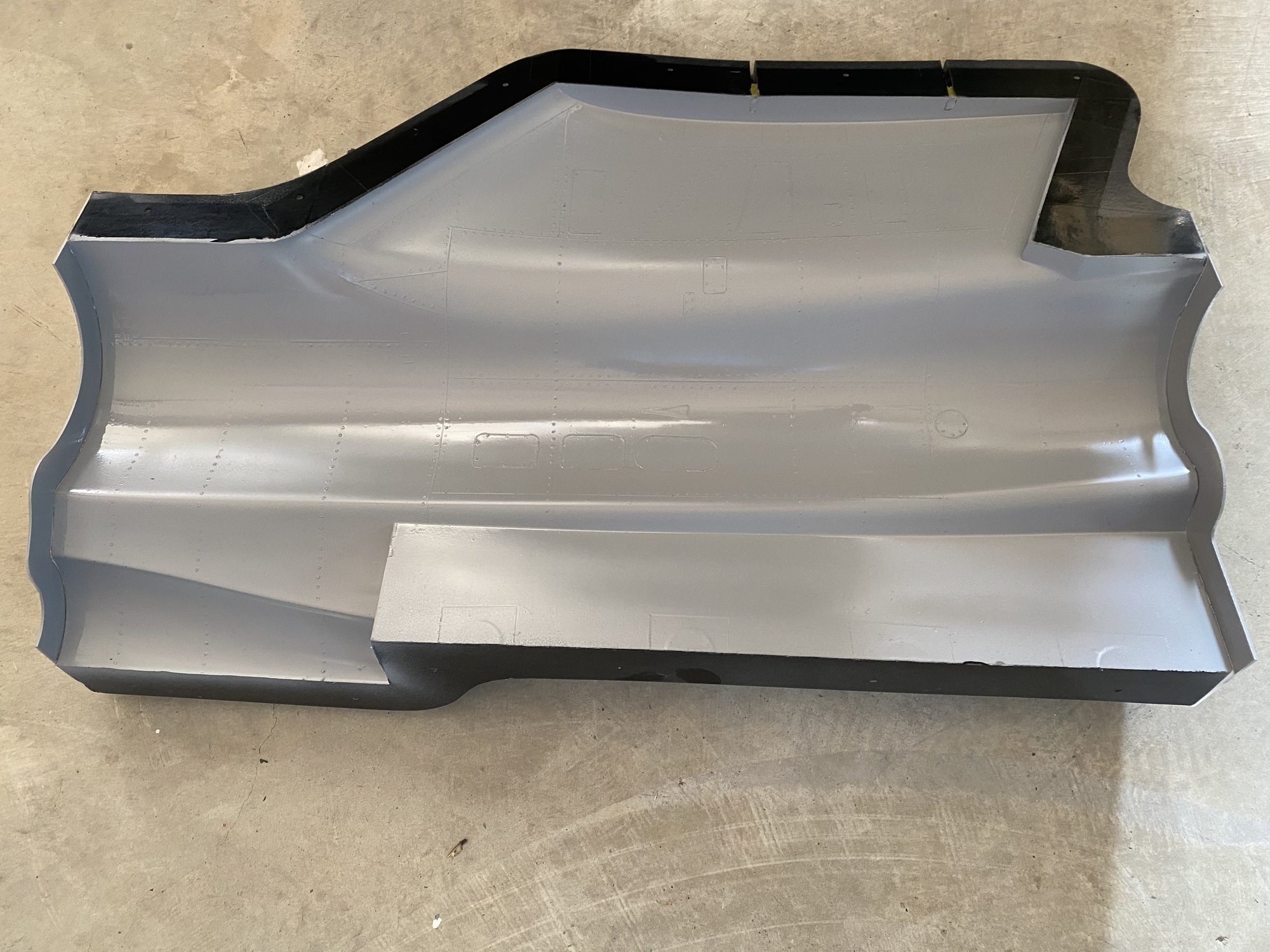
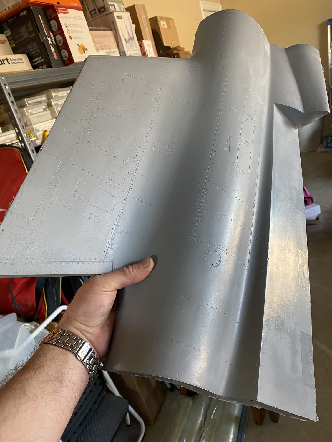
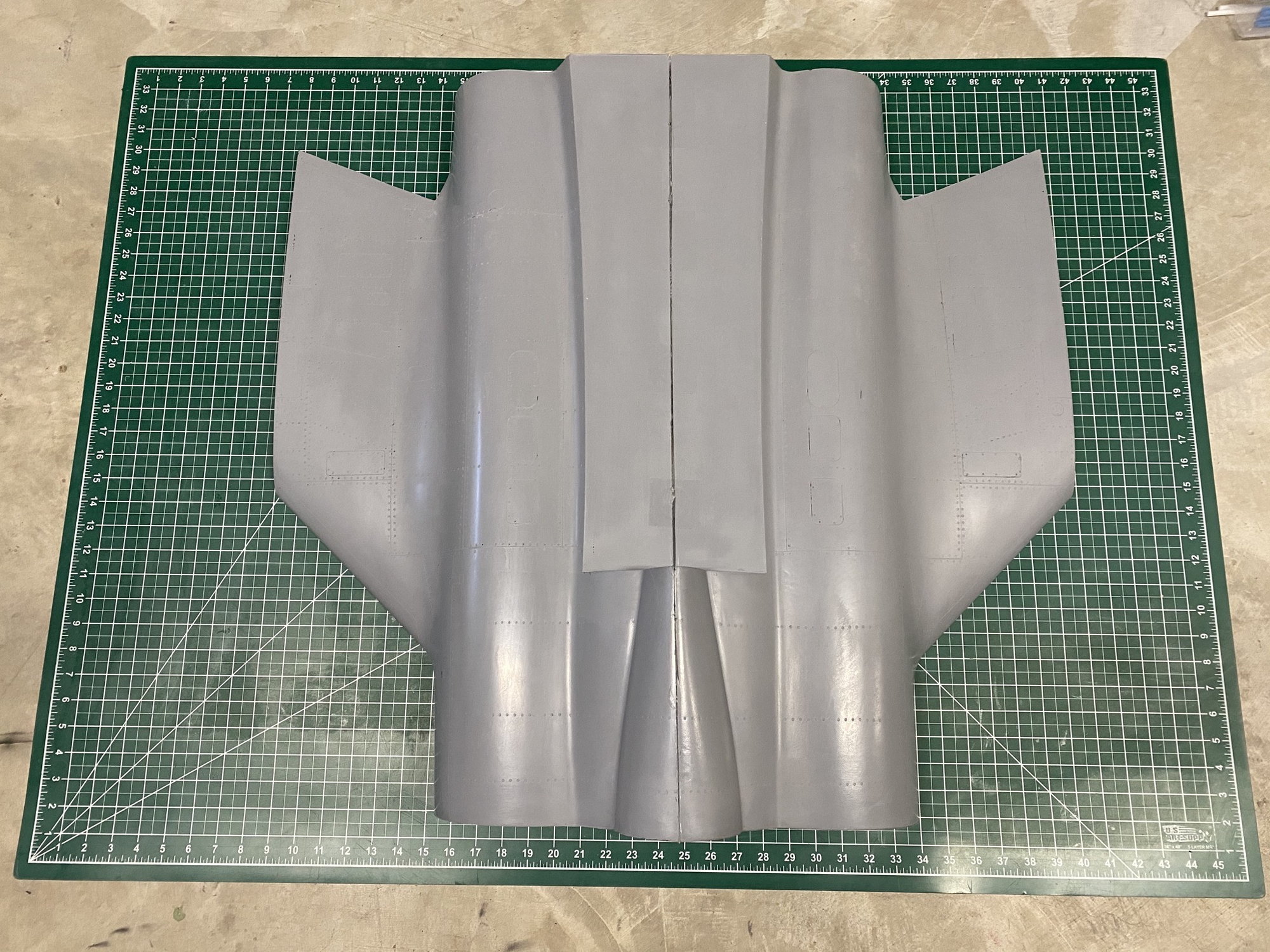
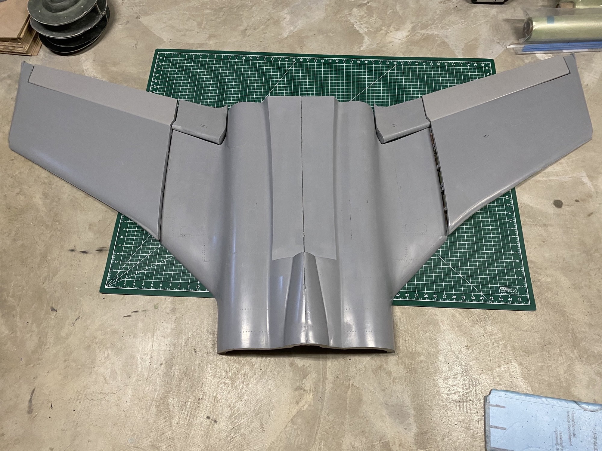
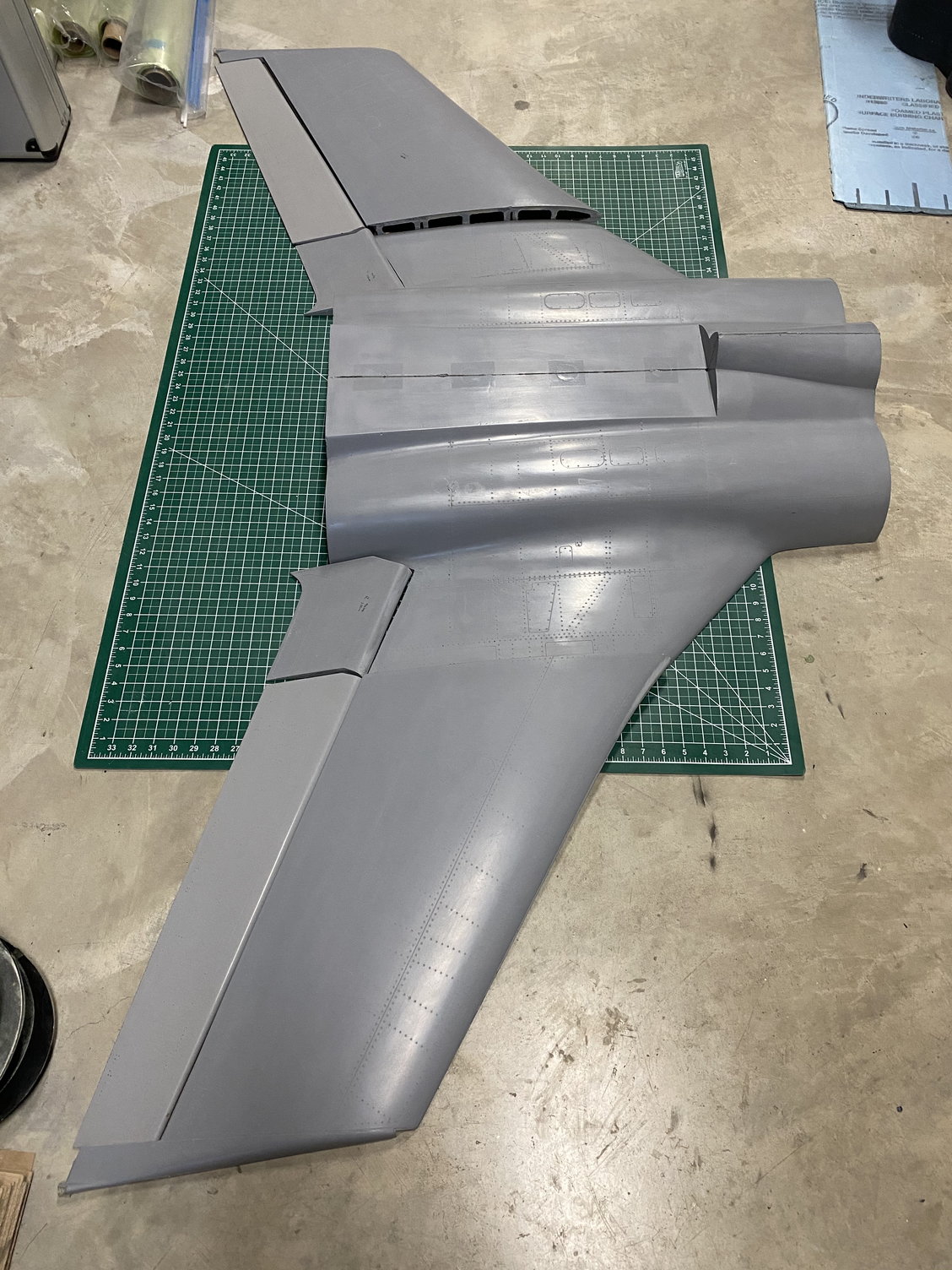
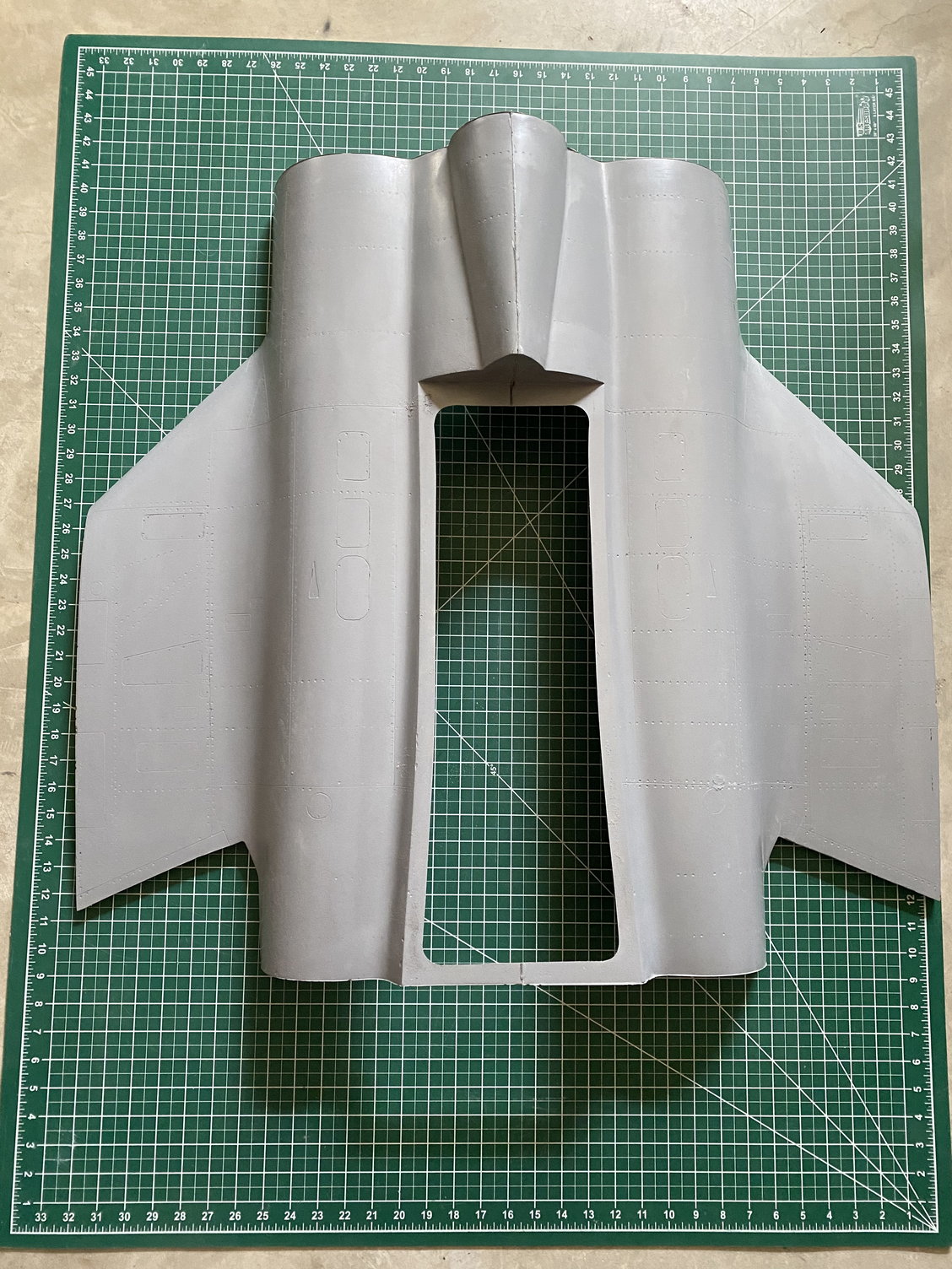
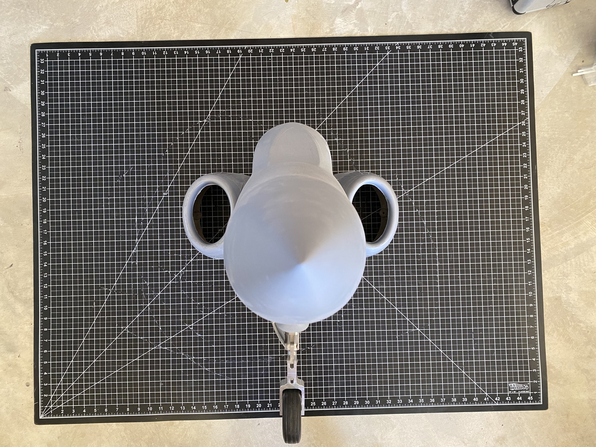
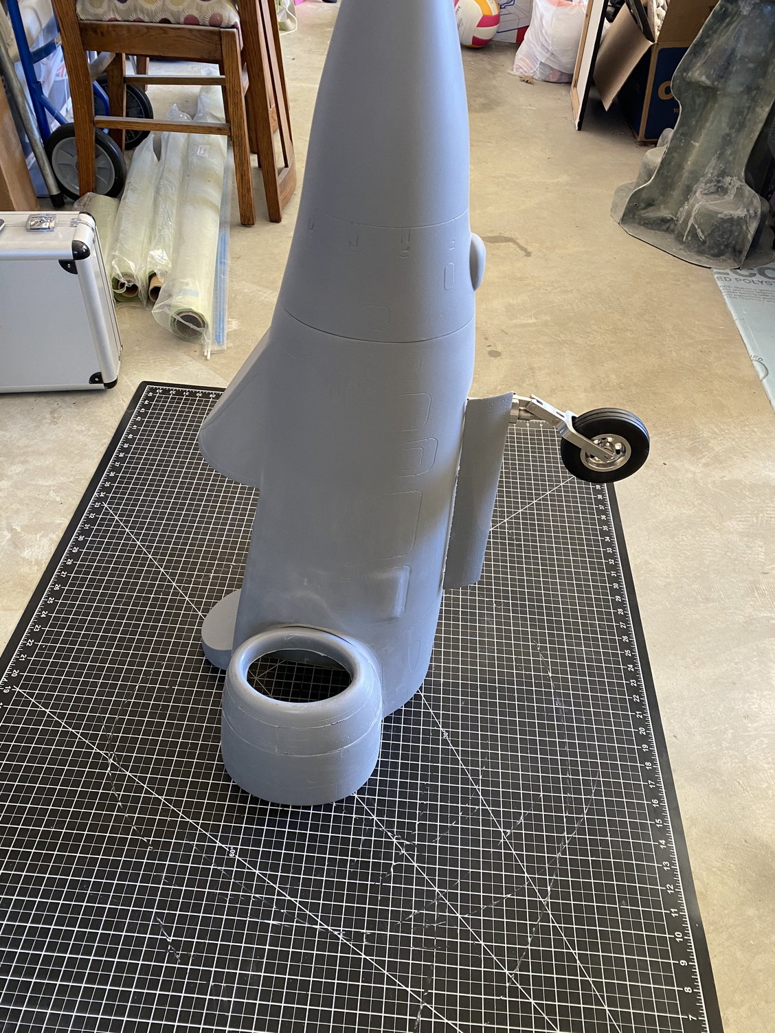
I completed the lower surface skins for the center fuselage, cut out the main gear openings and bonded them together. The main gear doors appear to fit well at this stage.
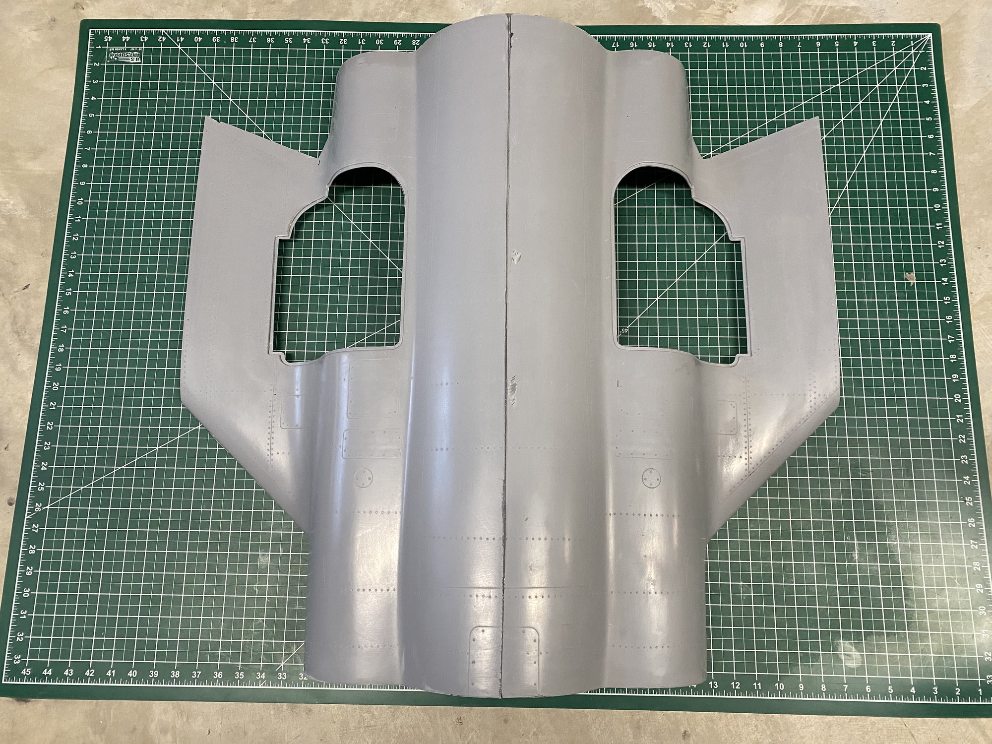
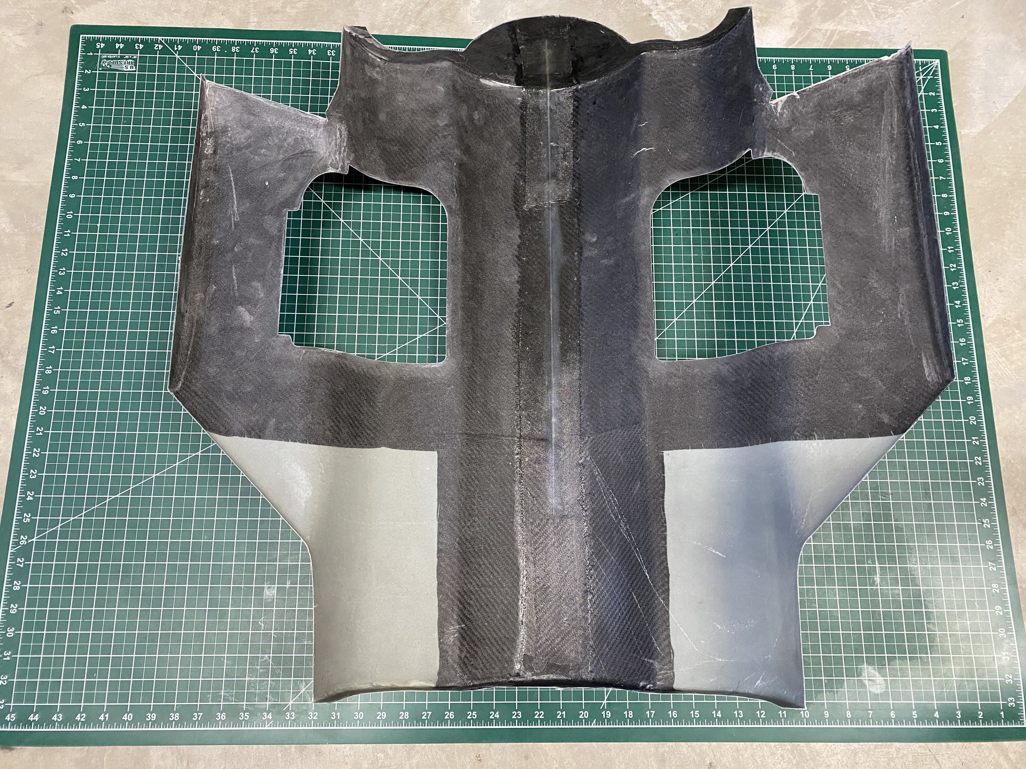
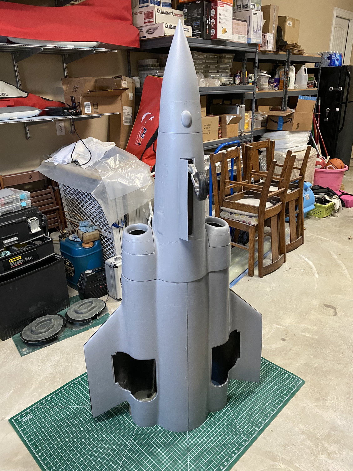
I just had to stand the fuselage pieces together just for inspiration. The center fuselage is just the skins. Feeling good about it so far. I need to remake the forward fuselage given how much better the center fuselage has turned out.
Paul
I completed the lower surface skins for the center fuselage, cut out the main gear openings and bonded them together. The main gear doors appear to fit well at this stage.
I just had to stand the fuselage pieces together just for inspiration. The center fuselage is just the skins. Feeling good about it so far. I need to remake the forward fuselage given how much better the center fuselage has turned out.
Paul

 Relatively quick job too, all things considered!... No thumbs up emoji, but insert here...
05-06-2020, 07:02 PM
Relatively quick job too, all things considered!... No thumbs up emoji, but insert here...
05-06-2020, 07:02 PM
#398
Thanks Ron - you need to reveal your secret project masterpiece sometime soon too
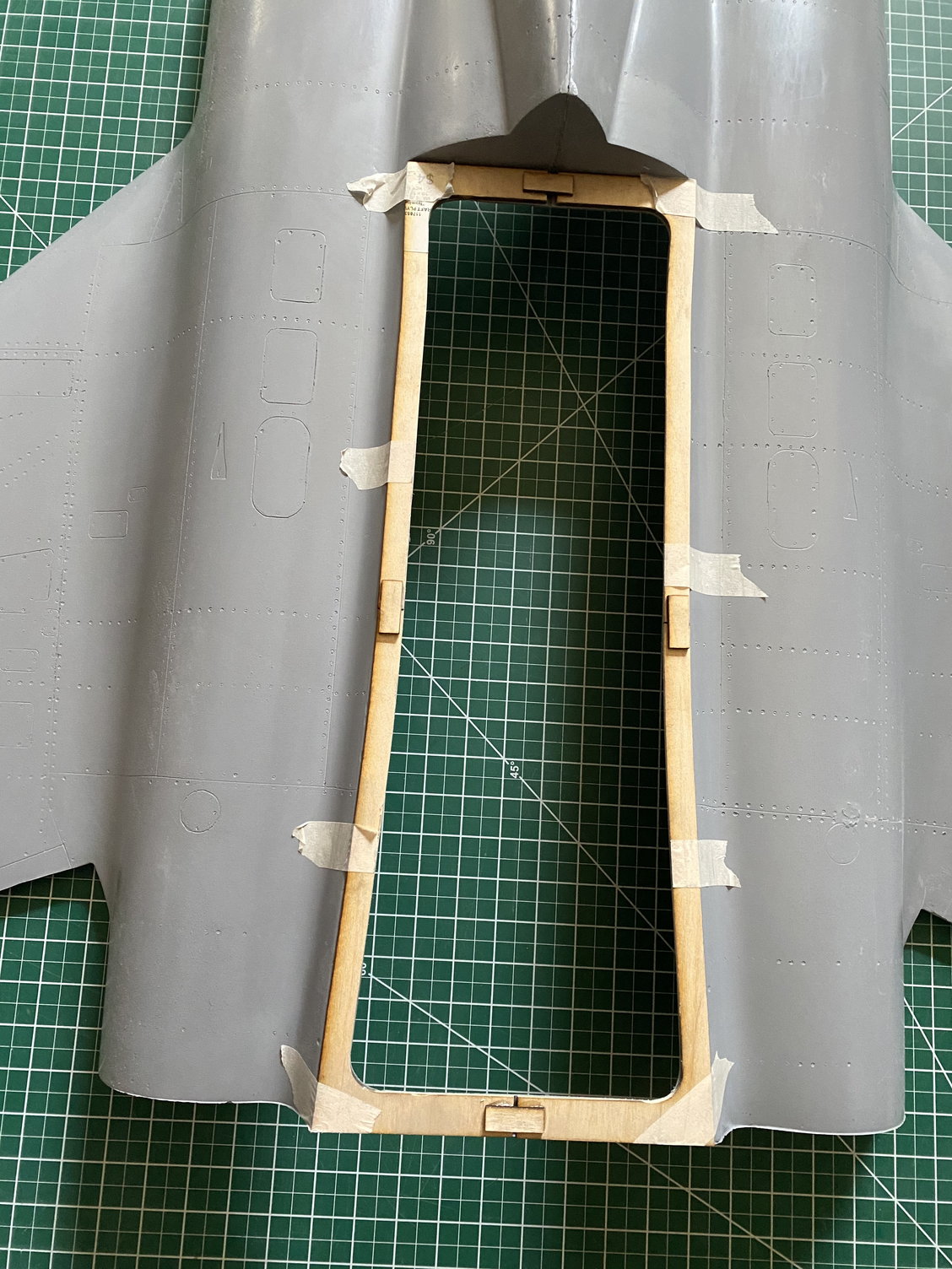
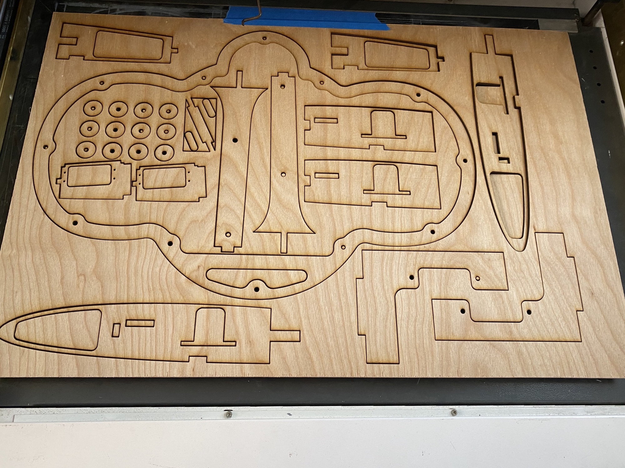
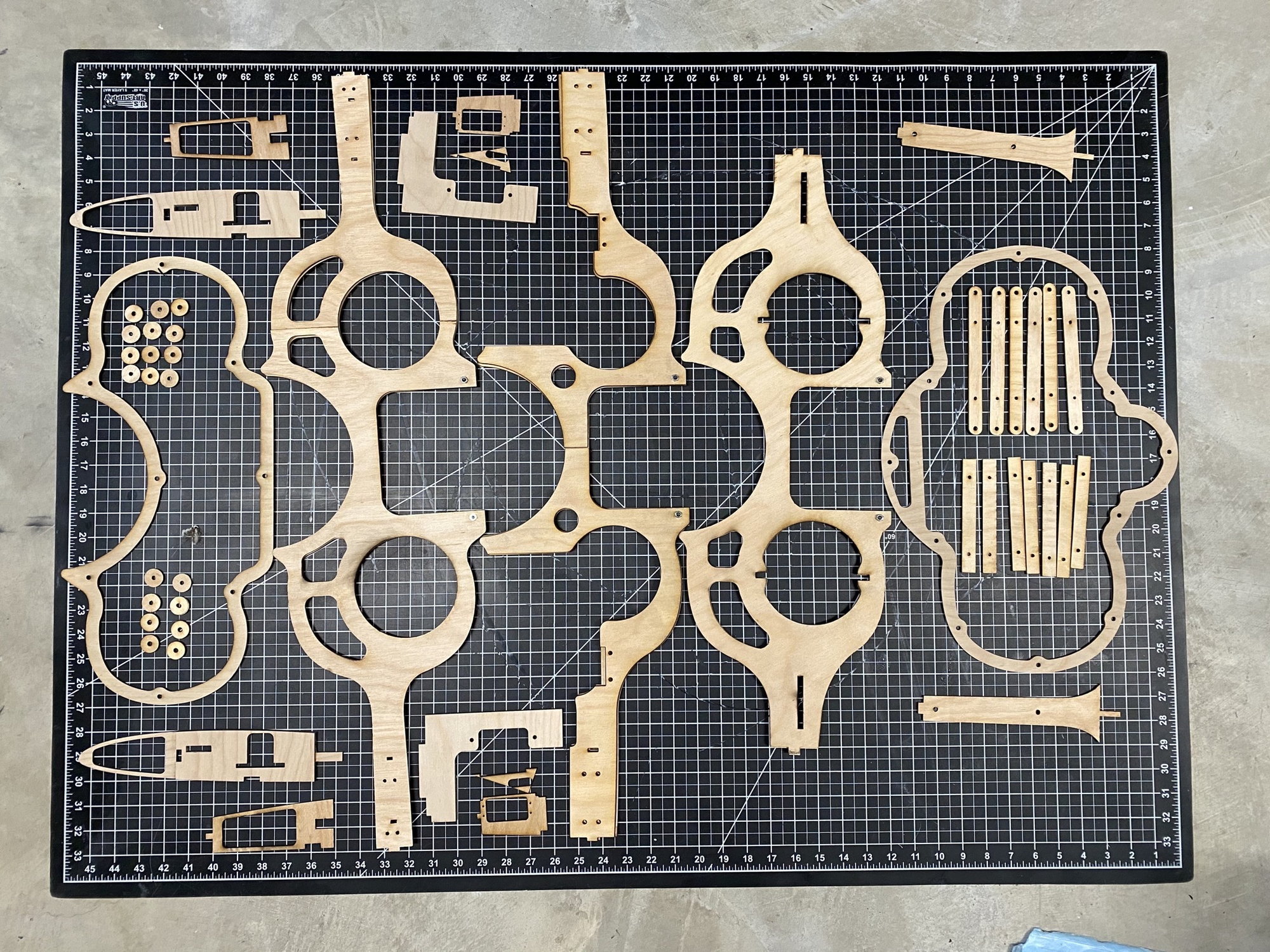
Working on the center fuselage internal structure. I progressed enough of the design to cut out most of the frames and ribs. Just one more frame to cut once I sort out the weapon bay door drive system.
Bonding the main structural frames together. 2 of the load-bearing frames will be 1/4" thick and the middle one 3/8" thick due to the major cut-out in its lower load path. All cut from aircraft grade 1/8" birch 5-ply.
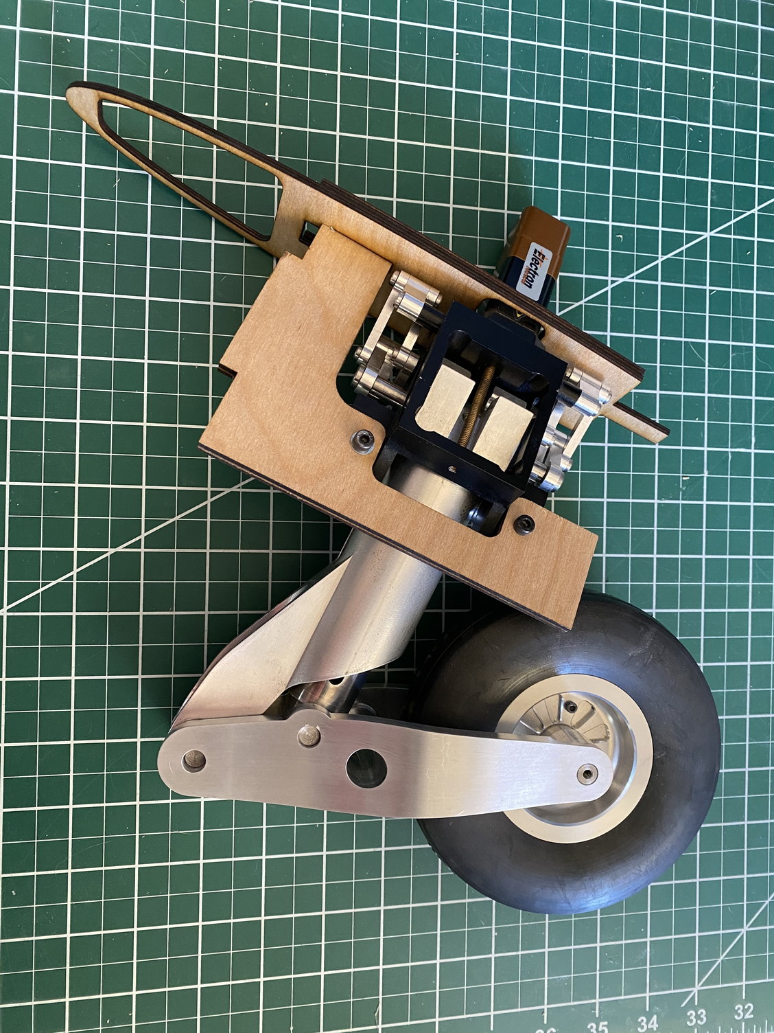
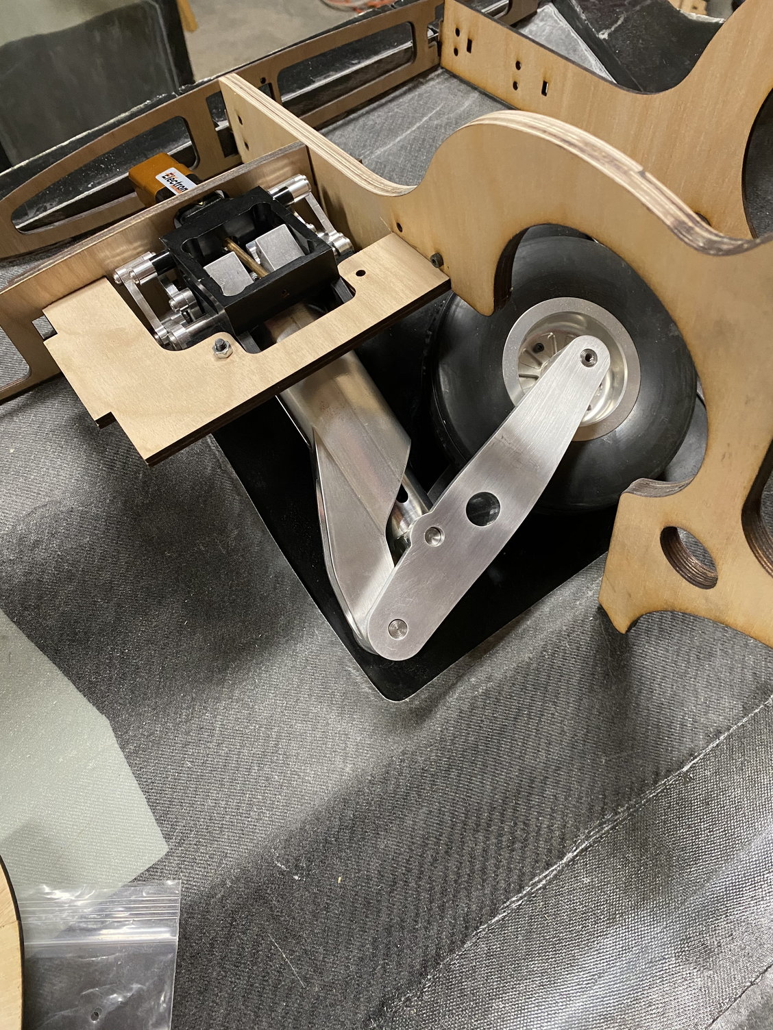
Test fitted the main gear to the mounting plate and into the fuselage. All looking good so far.
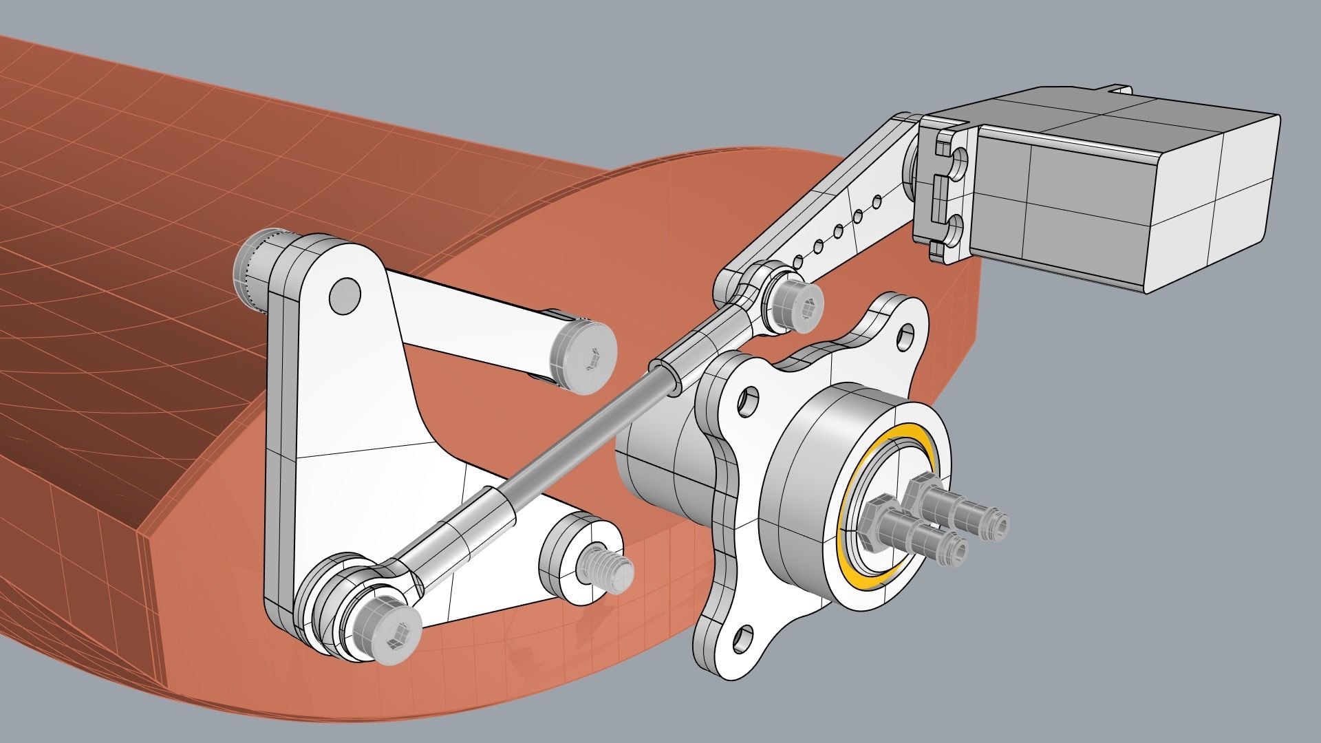
I have also been working out the design for the weapon bay door drive system, which includes the fuel and vent lines transfer system through the bearing. 85deg servo rotation gives 180deg weapon bay rotation.
Paul
Working on the center fuselage internal structure. I progressed enough of the design to cut out most of the frames and ribs. Just one more frame to cut once I sort out the weapon bay door drive system.
Bonding the main structural frames together. 2 of the load-bearing frames will be 1/4" thick and the middle one 3/8" thick due to the major cut-out in its lower load path. All cut from aircraft grade 1/8" birch 5-ply.
Test fitted the main gear to the mounting plate and into the fuselage. All looking good so far.
I have also been working out the design for the weapon bay door drive system, which includes the fuel and vent lines transfer system through the bearing. 85deg servo rotation gives 180deg weapon bay rotation.
Paul
