


1/7 Scale Blackburn Buccaneer All Composite Scratch Build
 09-09-2020, 07:19 PM
#476

After the show and tell at the model club and being able to stand back and look at the model, it was obvious that it had too much of a tail-down sit, and that the main gear were compressing about 1/3 of the available travel, even at the current weight. I had also noticed that with one gear compressed the main gear door would contact the ground.
So, I decided to make a small spacer to go in the shock strut to increase the preload on the main gear spring so that it wouldn't compress just sitting on the ground. I also included a long M3 bolt in the spacer to act as a limit stop under compression. After some trial and error without the spring fitted I had determined the correct length of the bolt to ensure that I retained a finger width gap between the gear door and the ground under full compression on one side. That should avoid any potential to grind off the gear door.
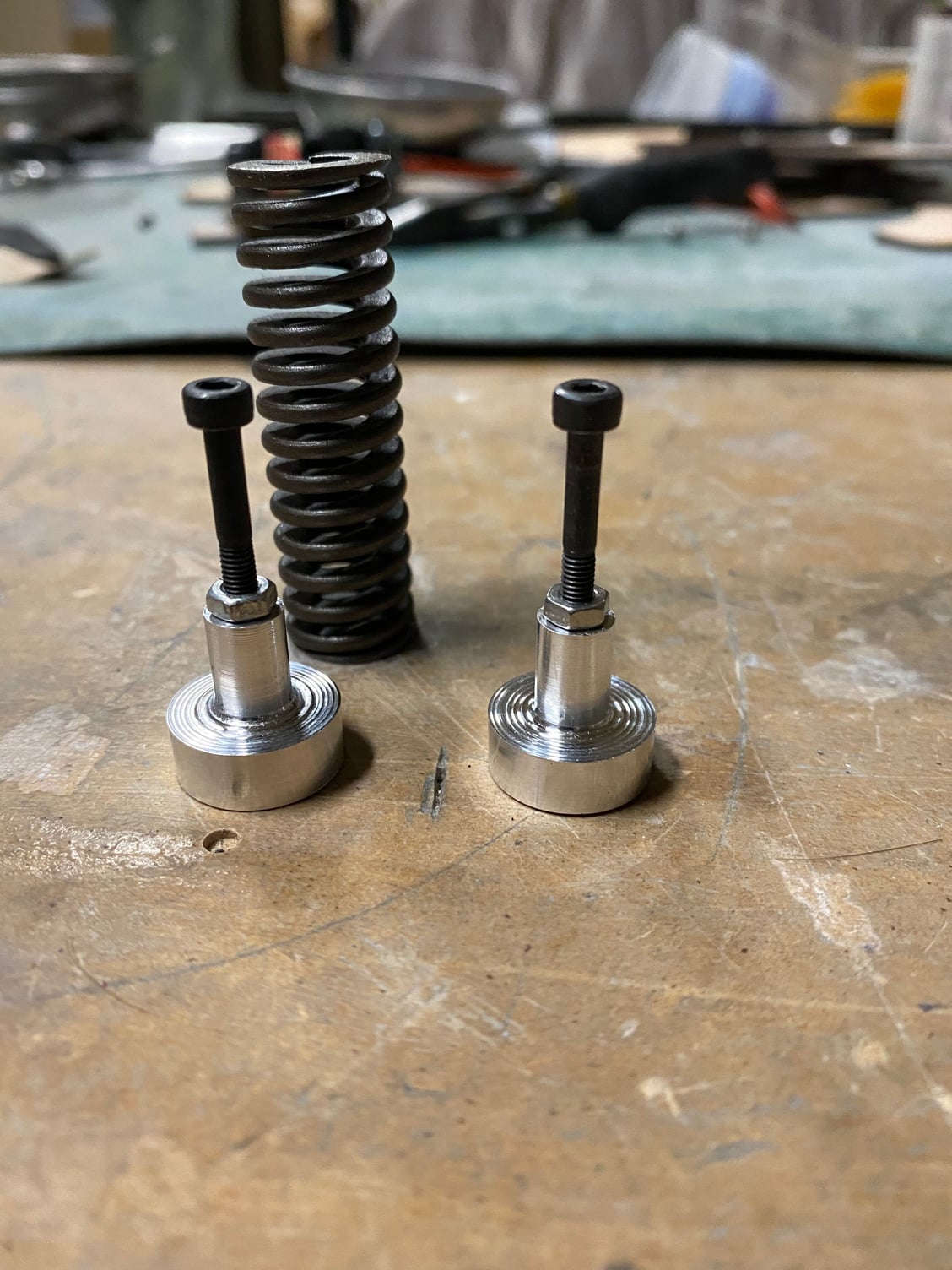
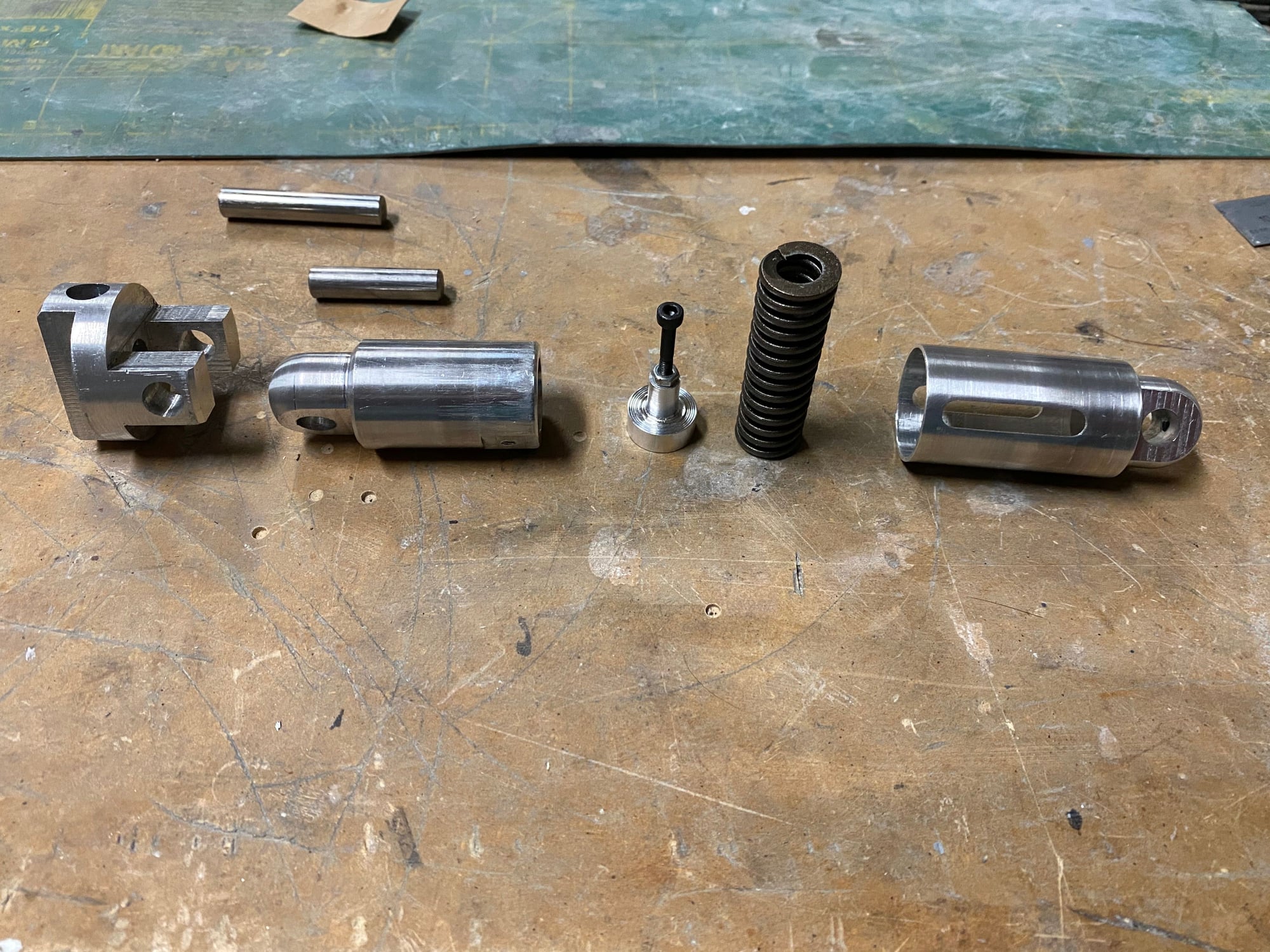
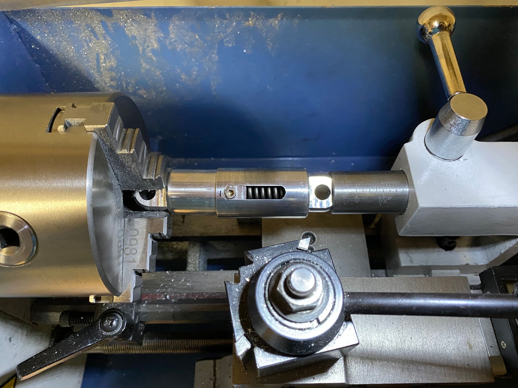
Re-assembling the shock strut was now hard given the additional spring compression needed, but I hit on the idea of using the lathe chuck and tail-stock to compress the unit so that I could insert the retaining bolts.
With the gear all re-assembled, I have now no gear compression just sitting on the gear, albeit it is not yet at full weight, the attitude looks a bit better plus the gear doors remain clear of the ground when compressed. I may still have to shorten the nose gear a little, but will defer that to later.
Paul
So, I decided to make a small spacer to go in the shock strut to increase the preload on the main gear spring so that it wouldn't compress just sitting on the ground. I also included a long M3 bolt in the spacer to act as a limit stop under compression. After some trial and error without the spring fitted I had determined the correct length of the bolt to ensure that I retained a finger width gap between the gear door and the ground under full compression on one side. That should avoid any potential to grind off the gear door.
Re-assembling the shock strut was now hard given the additional spring compression needed, but I hit on the idea of using the lathe chuck and tail-stock to compress the unit so that I could insert the retaining bolts.
With the gear all re-assembled, I have now no gear compression just sitting on the gear, albeit it is not yet at full weight, the attitude looks a bit better plus the gear doors remain clear of the ground when compressed. I may still have to shorten the nose gear a little, but will defer that to later.
Paul
Last edited by JSF-TC; 09-09-2020 at 07:24 PM.


 09-26-2020, 03:22 PM
#478
Over the last few weeks, I've been picking away at the countless small tasks that are required to bring the build to completion.
Ever since I completed the wiring and the fuselage disconnect panels, I realized that I had installed them backwards, due to the difficulty gaining access to the plugs when assembling/ dis-assembling the fuselage. I eventually resolved to fix this, so I cut off all the pins and sockets of the AMP connectors and re-terminated each of them and installed the plugs/ sockets the other way round. Now I have easy access to the plugs through both the cockpit and the fuselage hatch, without needing to be double-jointed. I also discovered that I had forgotten a plug/ socket on the forward/ mid fuselage break for the fuel pump and engine power cables. This was then added as part of the revised disconnect panel.

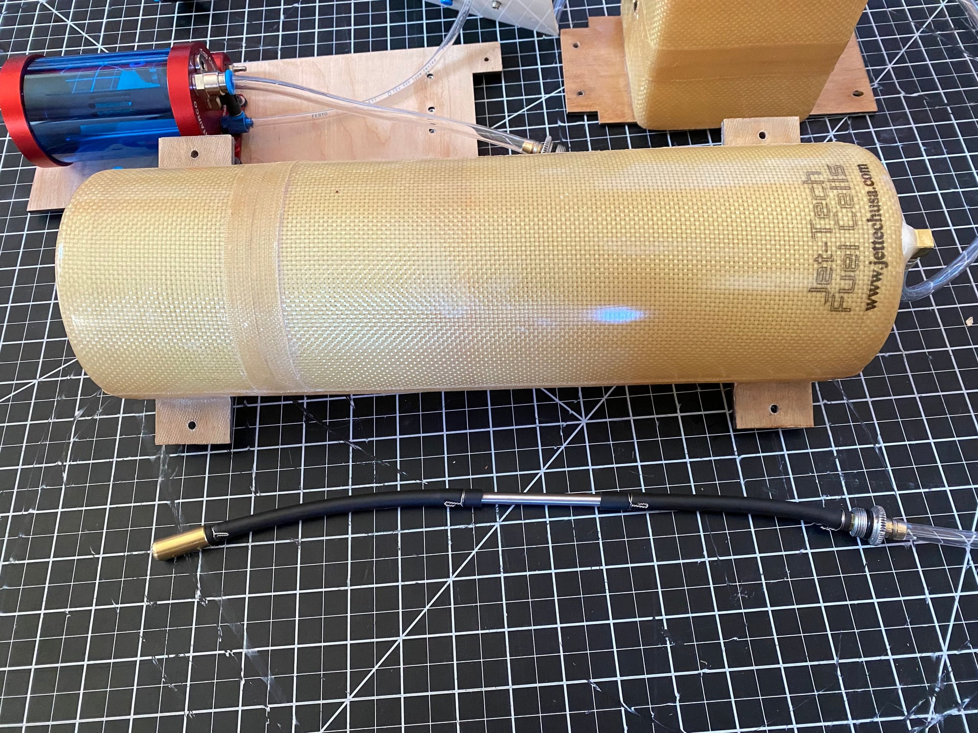
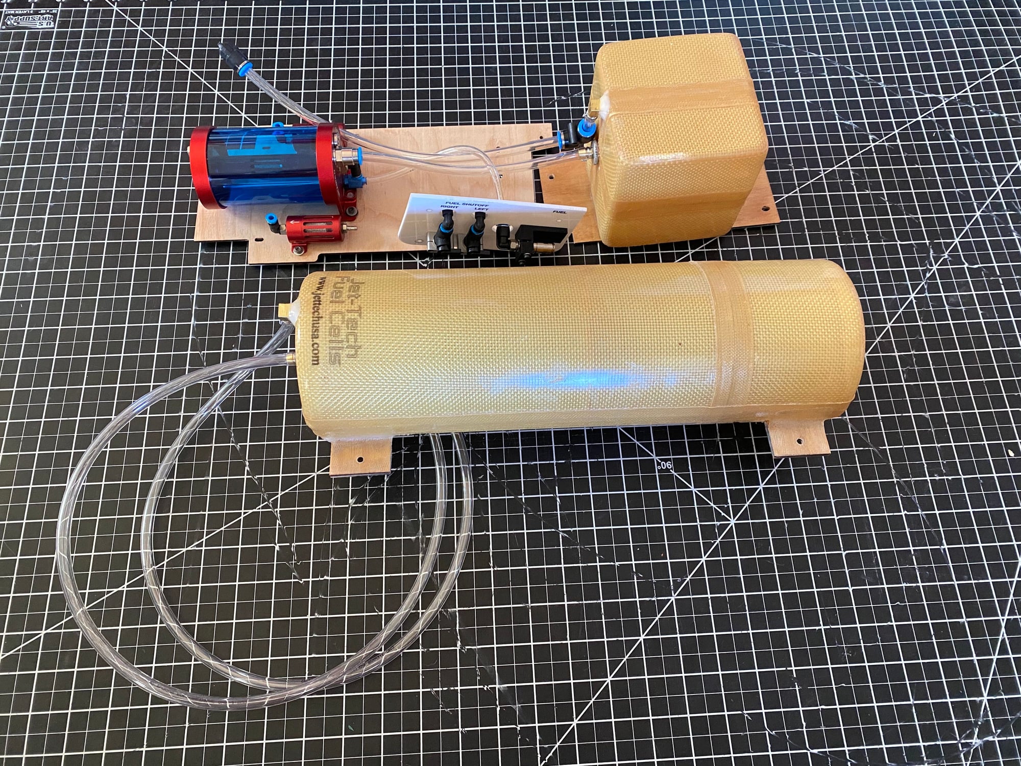
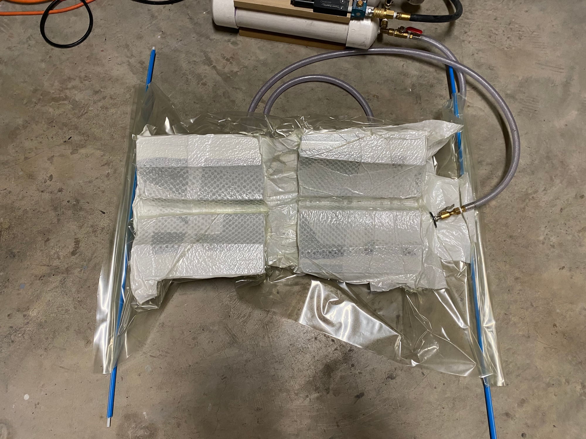
I then started on the fuel system install. 8mm Festo and Hi-Flow fittings throughout until the output from the Air Trap, where it will split into 2 4mm lines to the fuel pumps.
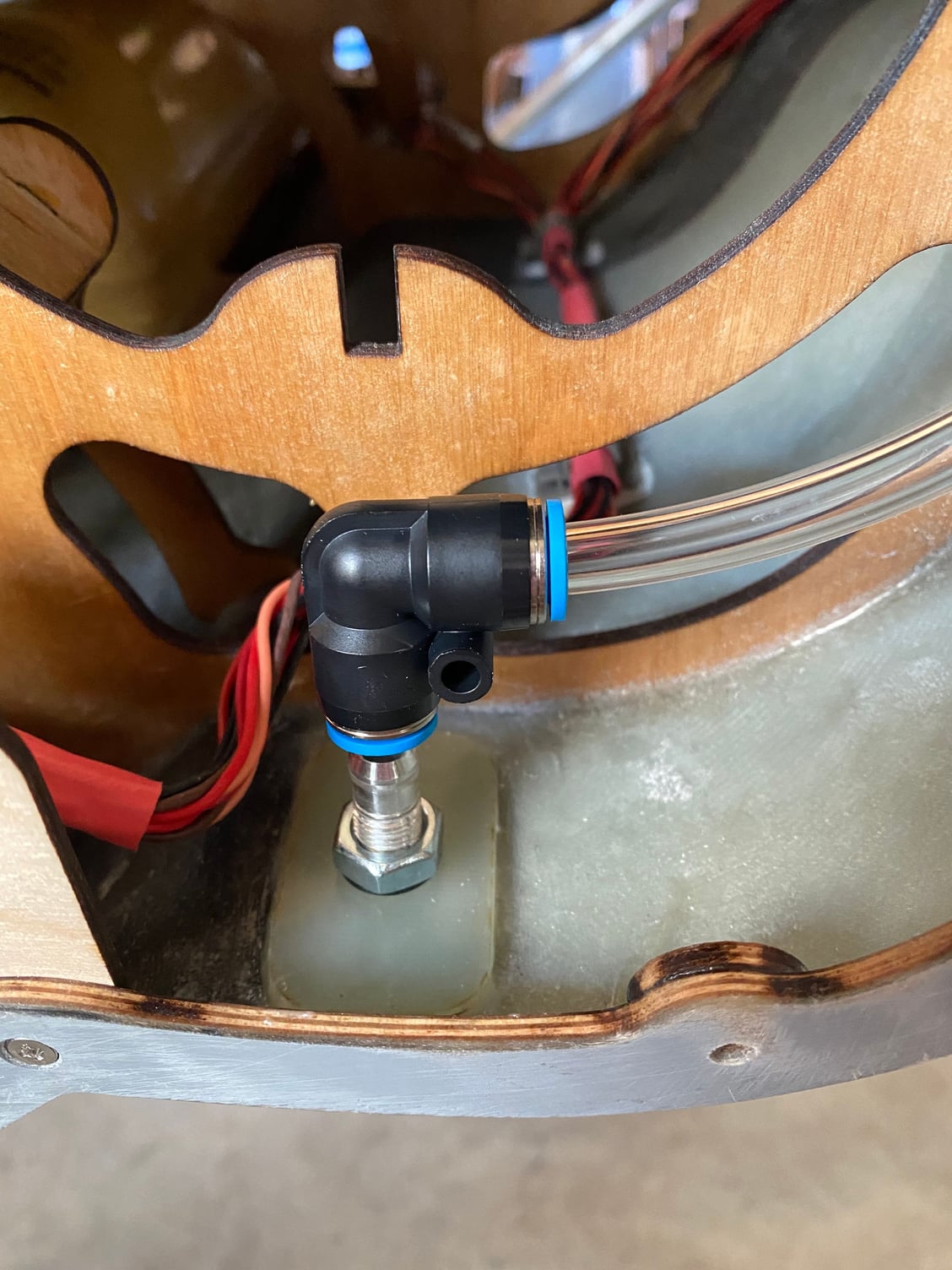
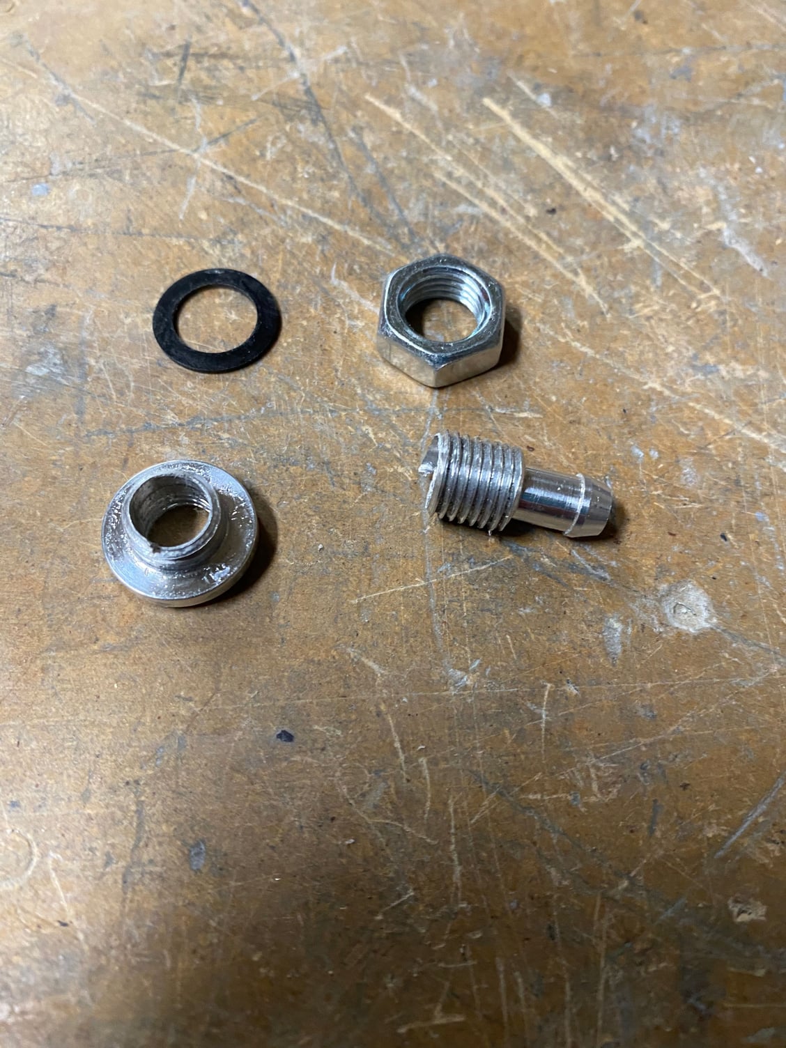
First up was the fuel vent and I found a good spot below the inlet. The Dreamworks fuel vent was mounted fully recessed by first epoxying in a 1.6mm G10 panel and then once cured drilling it out to just allow the head of the vent fitting to pass through. On the inner side, another 1.6mm G10 panel was bonded with a hole just big enough for the threaded portion of the fitting to pass through. Note of caution - if you over tighten the retaining nut on the vent, it splits in 2........ , so I had to order a replacement. A 90deg 8mm Festo allows connection to the vent line which wraps around the inlet to form a high point to break the siphon effect from the tank.


Ever since I completed the wiring and the fuselage disconnect panels, I realized that I had installed them backwards, due to the difficulty gaining access to the plugs when assembling/ dis-assembling the fuselage. I eventually resolved to fix this, so I cut off all the pins and sockets of the AMP connectors and re-terminated each of them and installed the plugs/ sockets the other way round. Now I have easy access to the plugs through both the cockpit and the fuselage hatch, without needing to be double-jointed. I also discovered that I had forgotten a plug/ socket on the forward/ mid fuselage break for the fuel pump and engine power cables. This was then added as part of the revised disconnect panel.
I then started on the fuel system install. 8mm Festo and Hi-Flow fittings throughout until the output from the Air Trap, where it will split into 2 4mm lines to the fuel pumps.
First up was the fuel vent and I found a good spot below the inlet. The Dreamworks fuel vent was mounted fully recessed by first epoxying in a 1.6mm G10 panel and then once cured drilling it out to just allow the head of the vent fitting to pass through. On the inner side, another 1.6mm G10 panel was bonded with a hole just big enough for the threaded portion of the fitting to pass through. Note of caution - if you over tighten the retaining nut on the vent, it splits in 2........
, so I had to order a replacement. A 90deg 8mm Festo allows connection to the vent line which wraps around the inlet to form a high point to break the siphon effect from the tank.
Last edited by JSF-TC; 09-26-2020 at 03:40 PM.
09-26-2020, 03:33 PM
#479
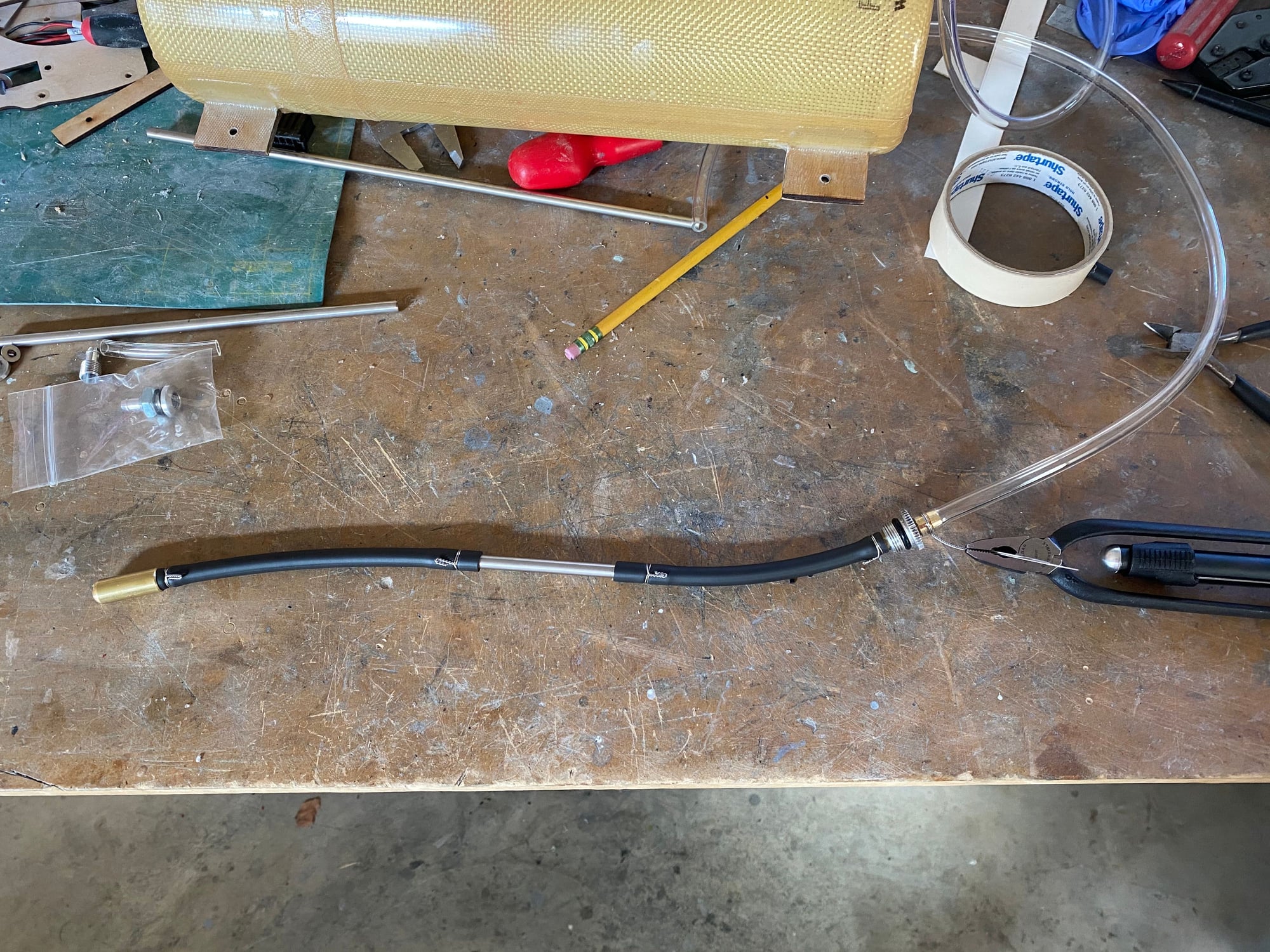
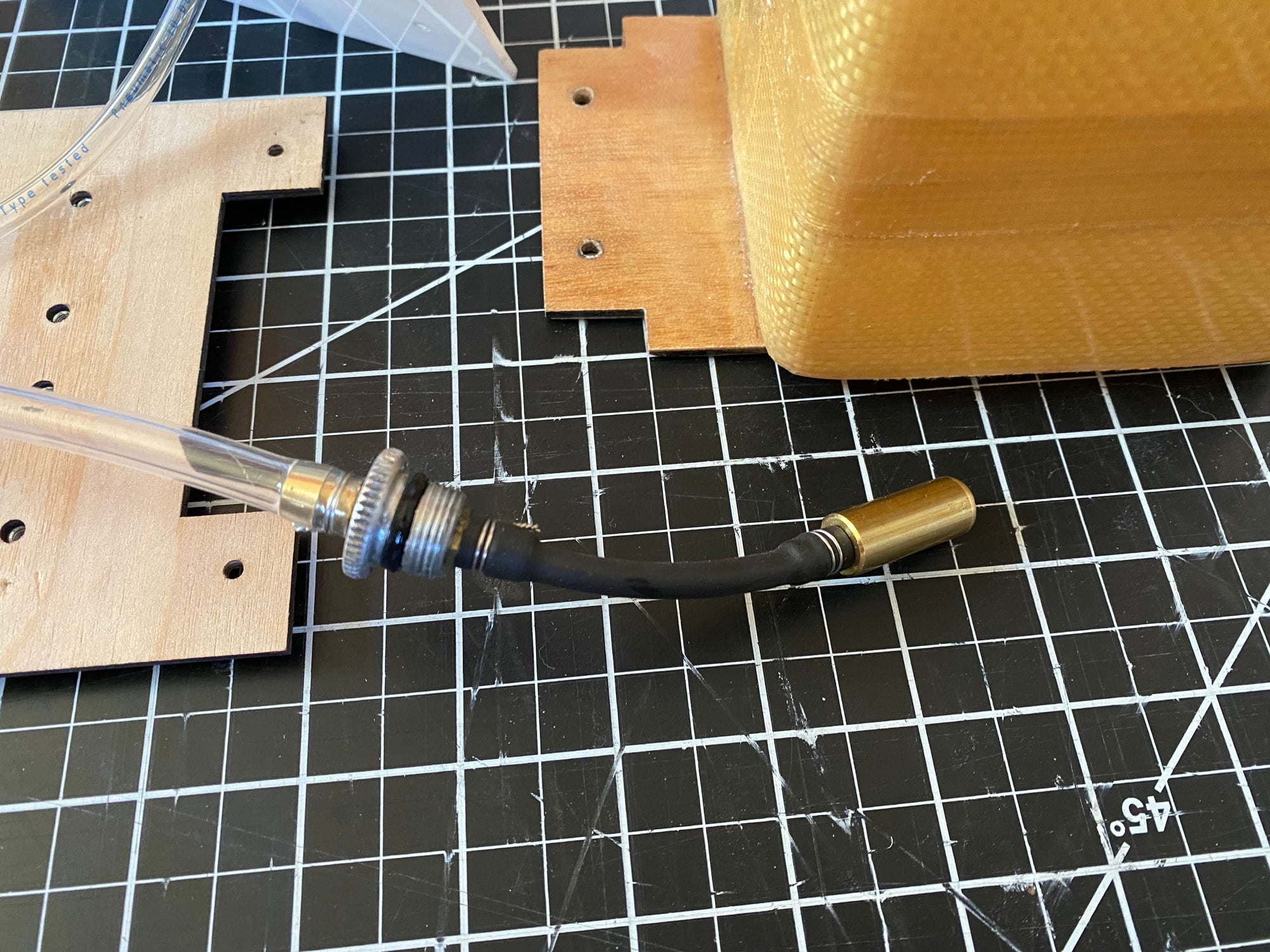
The fuel tank internals were then completed, using Viton fuel tube and a stainless steel 6mm tube to bridge the baffle in the main tank.
Space is left on the main fuel tray to mount the fuel pumps once I order the engines.
Space is left on the main fuel tray to mount the fuel pumps once I order the engines.
Last edited by JSF-TC; 09-26-2020 at 03:45 PM.
The following users liked this post:
skunkwurk (11-03-2020)
09-26-2020, 03:38 PM
#480
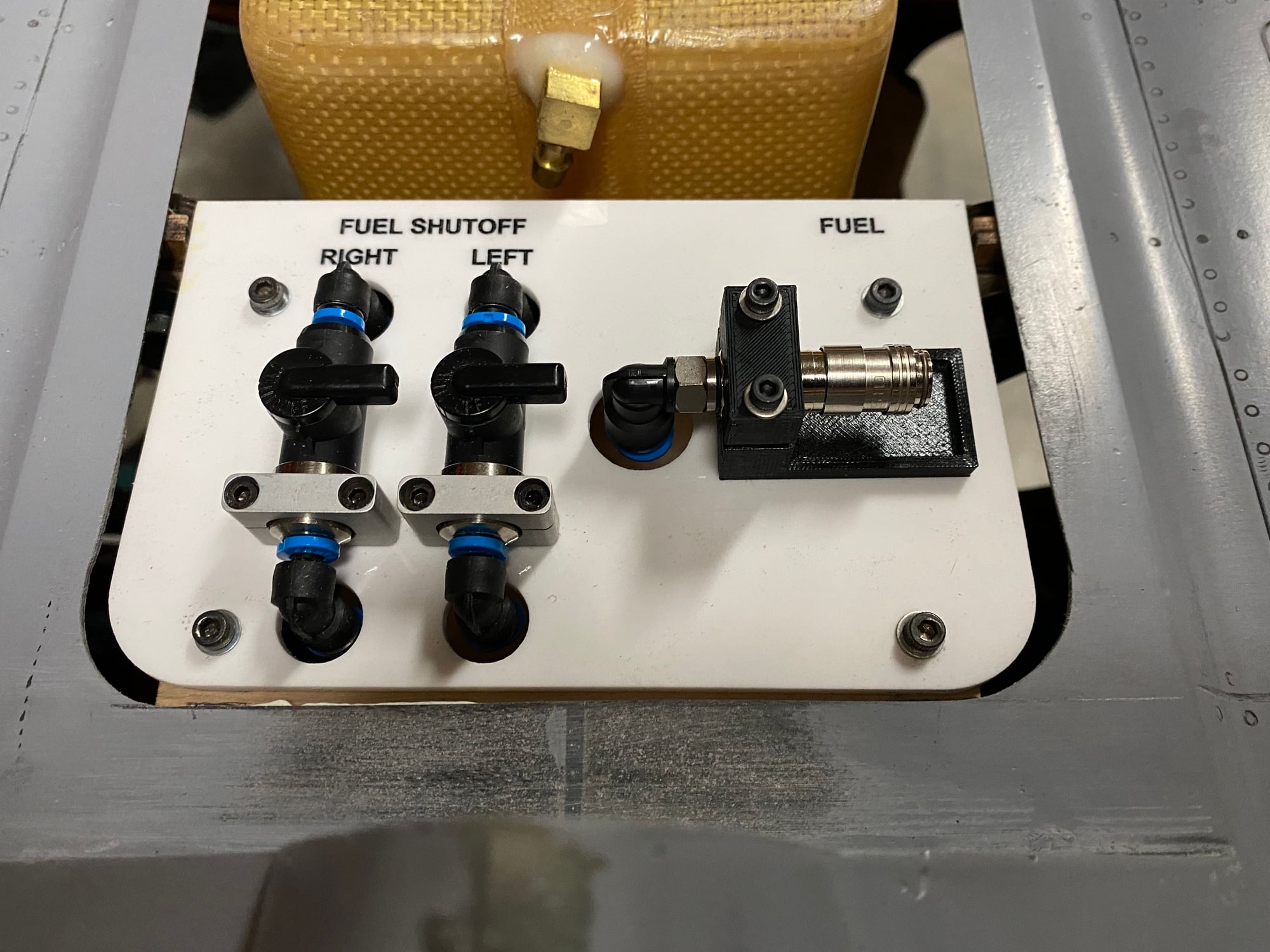
Last up so far for the fuel system is the main fuel panel holding the 2 fuel shut-off valves and the fueling connection.
This is mounted under the main fuselage access hatch, and they are mounted on a piece of laser cut and engraved 3mm acrylic. Black paint was rubbed into the engraving for the labeling.
A 3D printed bracket mounts this panel to the forward cross frame and allows easy access to the items below if needed.
Paul
09-27-2020, 11:06 AM
#482
Dave,
Thanks
Apart from replacing the Intairco Air Trap and filters by a MAP Air Trap , I'm not sure what you would remove/ simplify from the fuel system.........???
Sometimes designing for neatness & maintainability does add additional parts above that for basic functionality..
Paul
Thanks
Apart from replacing the Intairco Air Trap and filters by a MAP Air Trap
, I'm not sure what you would remove/ simplify from the fuel system.........???Sometimes designing for neatness & maintainability does add additional parts above that for basic functionality..
Paul
10-10-2020, 09:08 AM
#484
Next up was the canopy. For the initial flight, I decided to just 3D print a canopy, and work on the clear vacuum formed one later when I detail and paint the model.
I decided to attach the canopy by running 2 long piano wire rods inserted from within the radome which would engage in the forward fuselage at both ends of the canopy. This has the advantage that there would be no visible catches, and it would be simple and quick to remove. The path taken by the wire was incorporated into the 3D printed canopy, with a hole big enough that a brass tube could be inserted through it to provide a close tolerance wire guide.
The 3D printed canopy was glassed and primed just to give a finished look to it. A separate canopy plug will be printed and finished for the vacuum formed part.


Paul
I decided to attach the canopy by running 2 long piano wire rods inserted from within the radome which would engage in the forward fuselage at both ends of the canopy. This has the advantage that there would be no visible catches, and it would be simple and quick to remove. The path taken by the wire was incorporated into the 3D printed canopy, with a hole big enough that a brass tube could be inserted through it to provide a close tolerance wire guide.
The 3D printed canopy was glassed and primed just to give a finished look to it. A separate canopy plug will be printed and finished for the vacuum formed part.
Paul
10-10-2020, 09:15 AM
#485
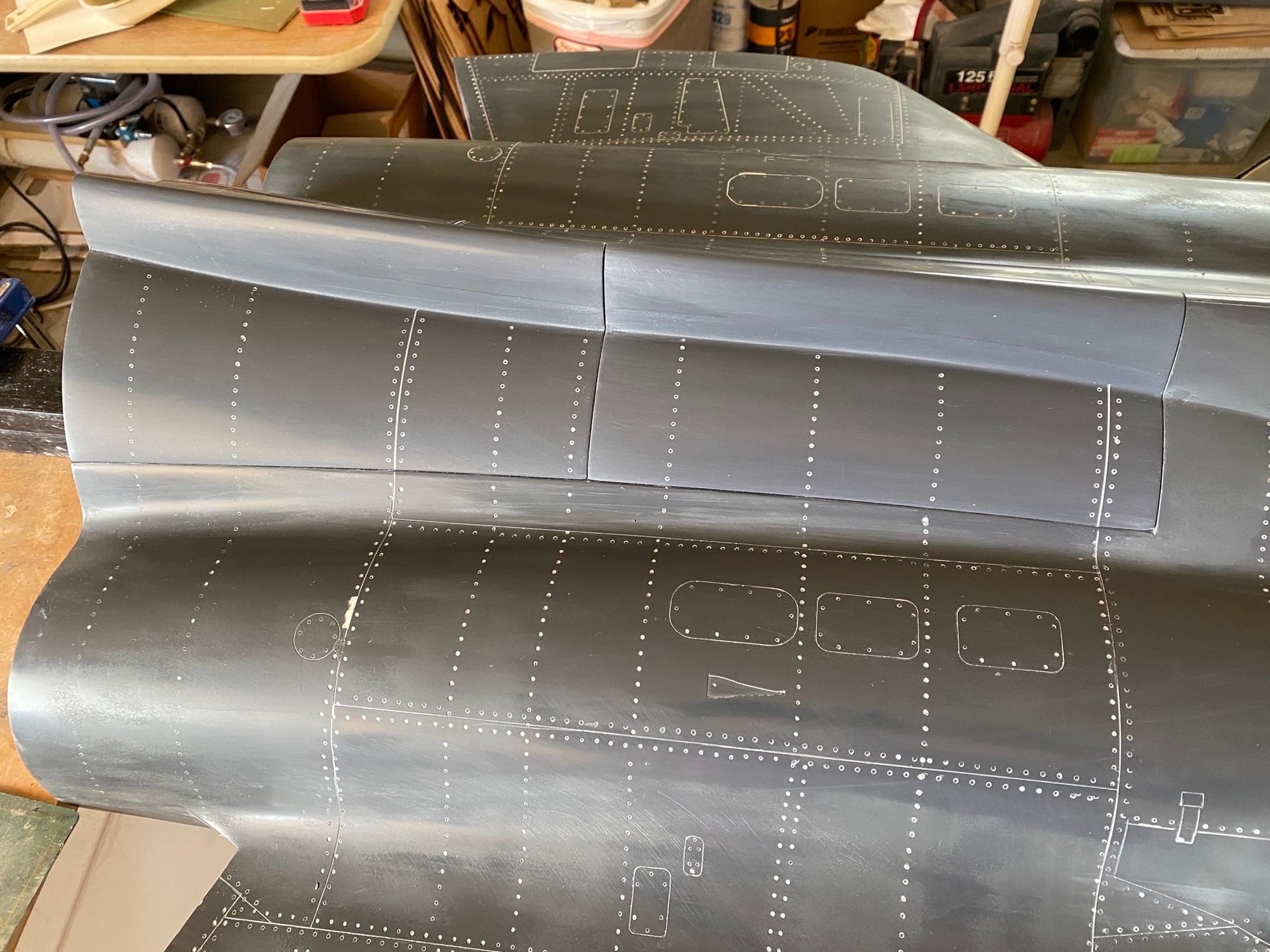
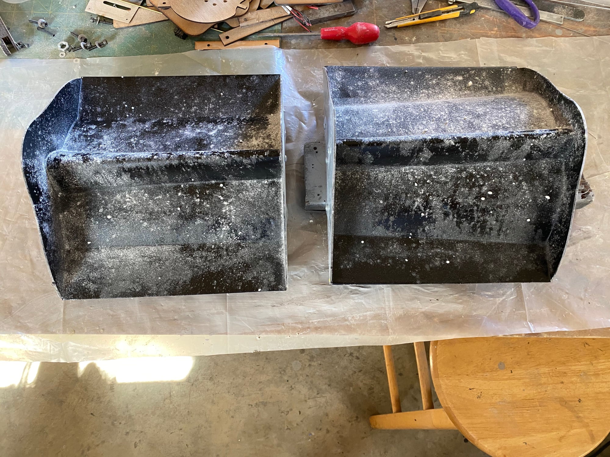
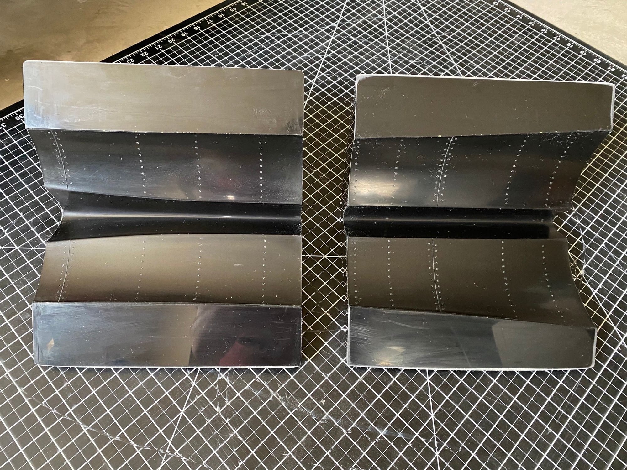
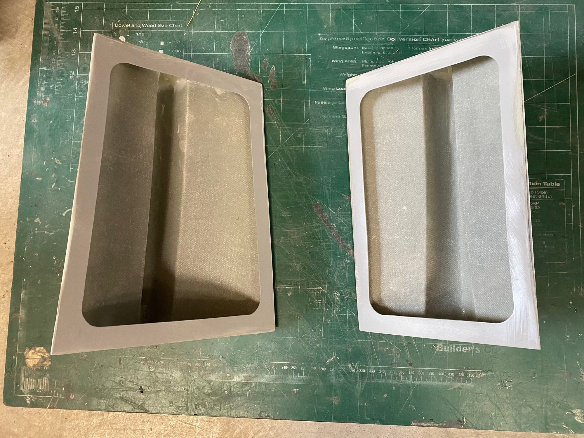
The last parts to be molded were the fuselage access hatches. The plugs were completed a long time ago, and just needed a final finish sanding and detailing before making the molds. I used the same process as the rest of the plugs/ molds, so just some photos posted below.
I tried a new layup, using 2 layers of 3oz + 1 layer of 6oz glass cloth and I was very impressed. If I remake the fuselage I will probably use that throughout to see how much weight savings I can gain.
Paul
I tried a new layup, using 2 layers of 3oz + 1 layer of 6oz glass cloth and I was very impressed. If I remake the fuselage I will probably use that throughout to see how much weight savings I can gain.
Paul
10-10-2020, 09:21 AM
#486
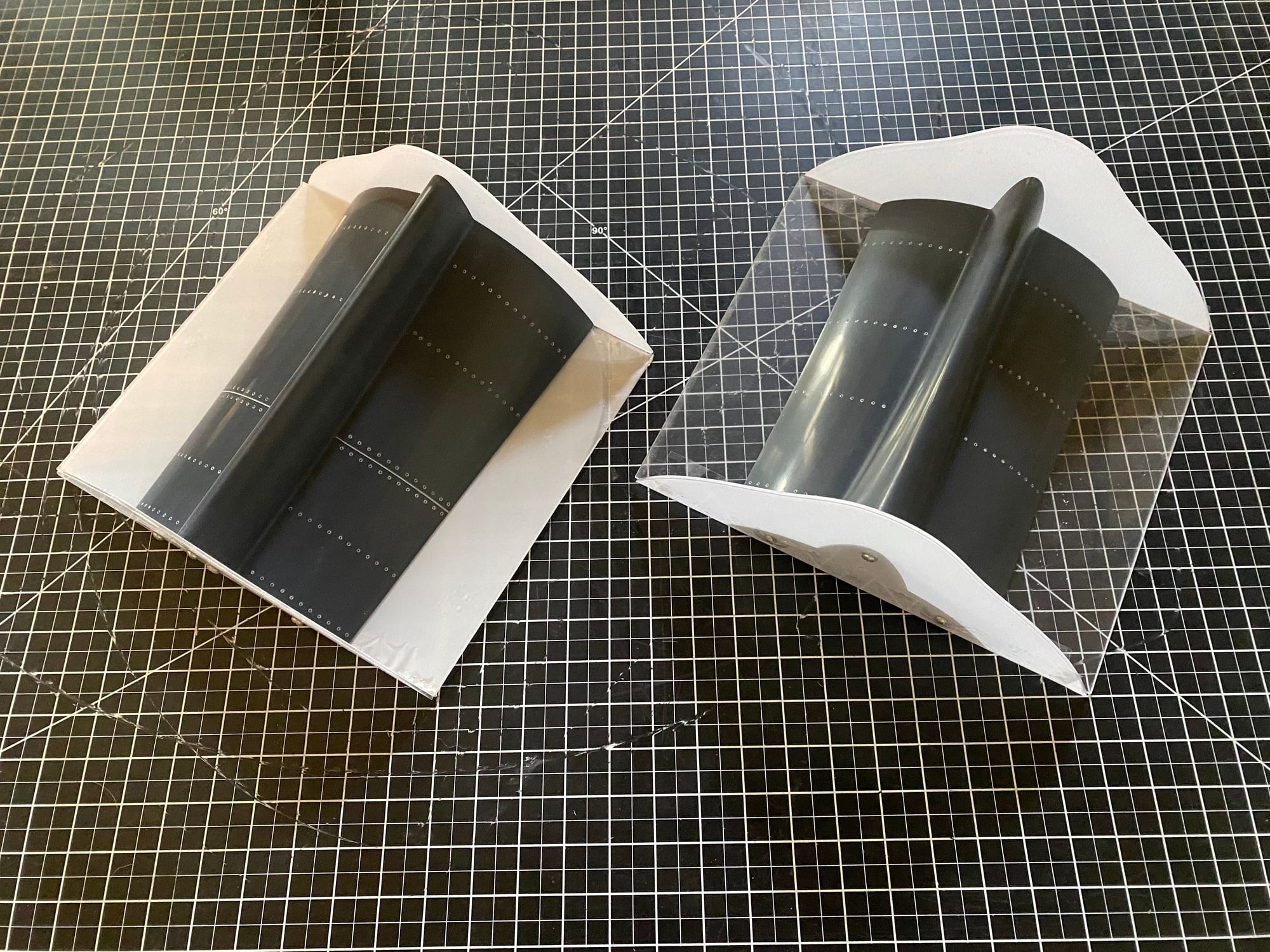
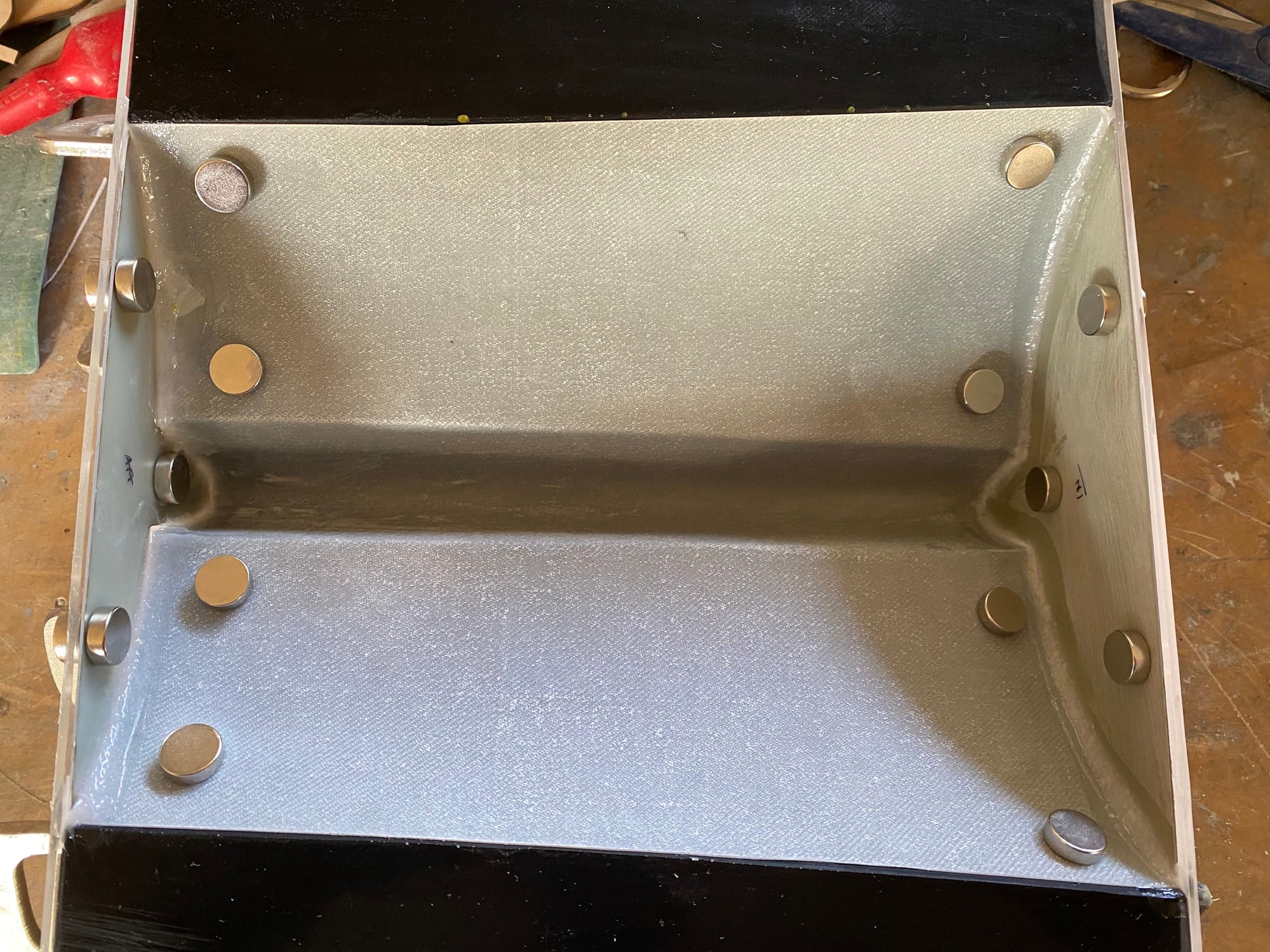
To finish the hatches, I laser cut the end plates and bottom plates out of 0.8mm (1/32") G-10. It doesn't cut well, but with 5 passes the parts can be removed and cleaned up.
I then used rare-earth magnets to hold the hatch skins and end plates in place in the mold while a bead of epoxy cured. With the end plates cured, the bottom plates were held with magnets onto the fuselage after parcel tape and release agent were applied to the fuselage and then hatches then bonded into place, one at a time.

Paul
I then used rare-earth magnets to hold the hatch skins and end plates in place in the mold while a bead of epoxy cured. With the end plates cured, the bottom plates were held with magnets onto the fuselage after parcel tape and release agent were applied to the fuselage and then hatches then bonded into place, one at a time.
Paul
The following users liked this post:
grbaker (11-02-2020)

The following users liked this post:
David Gladwin (11-03-2020)
11-02-2020, 01:14 PM
#488
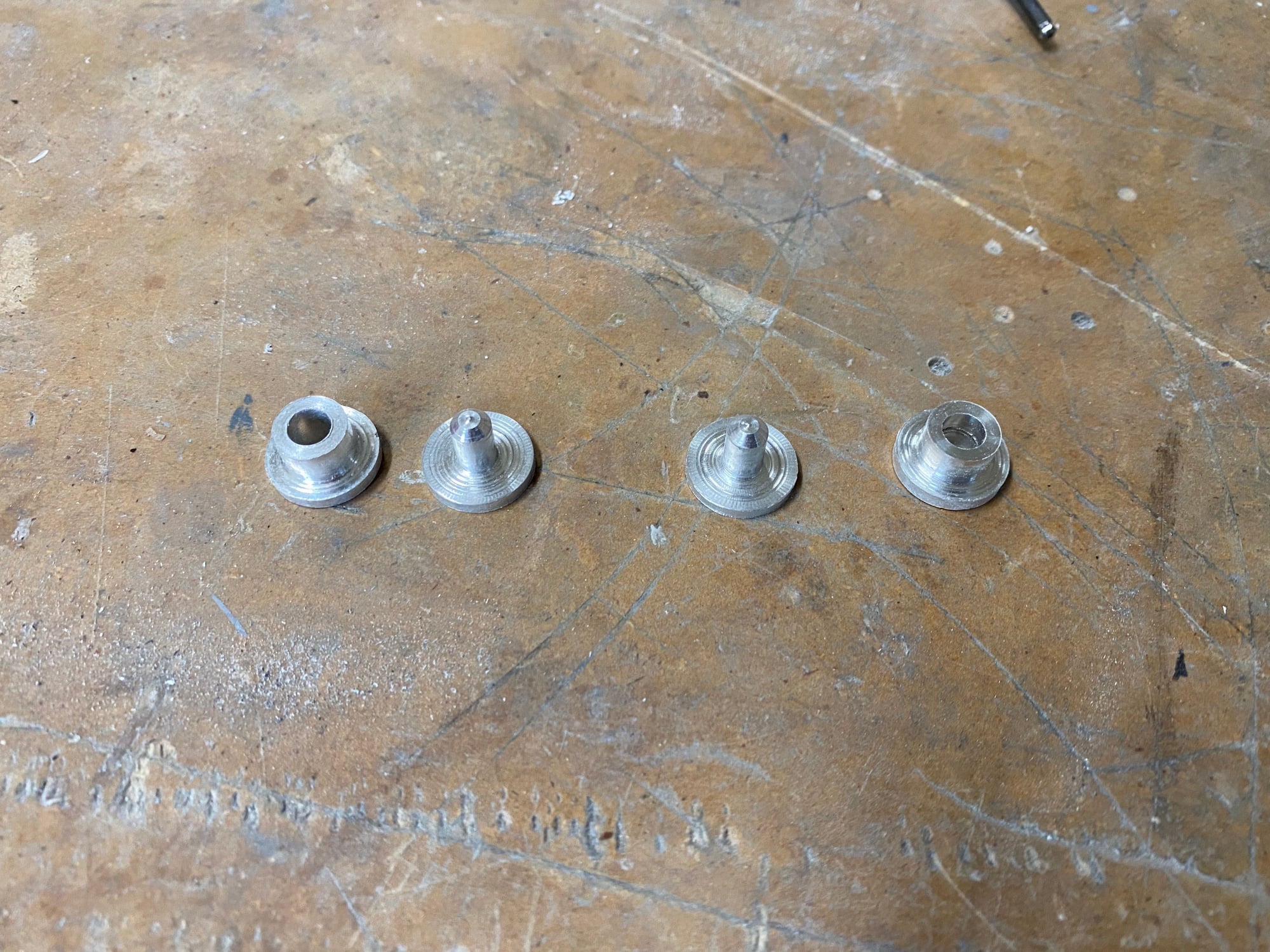
Still continuing with lots of little jobs. After completing the hatch layups, I turned down a couple of rear hatch location pins and sockets, match drilled the fuselage and epoxied them in place. I laser cut a couple of rear hatch hooks out of 1.6mm G10 and fixed them in place at the forward end of the rear hatch. The forward hatch is retained by two sprung hatch pins.
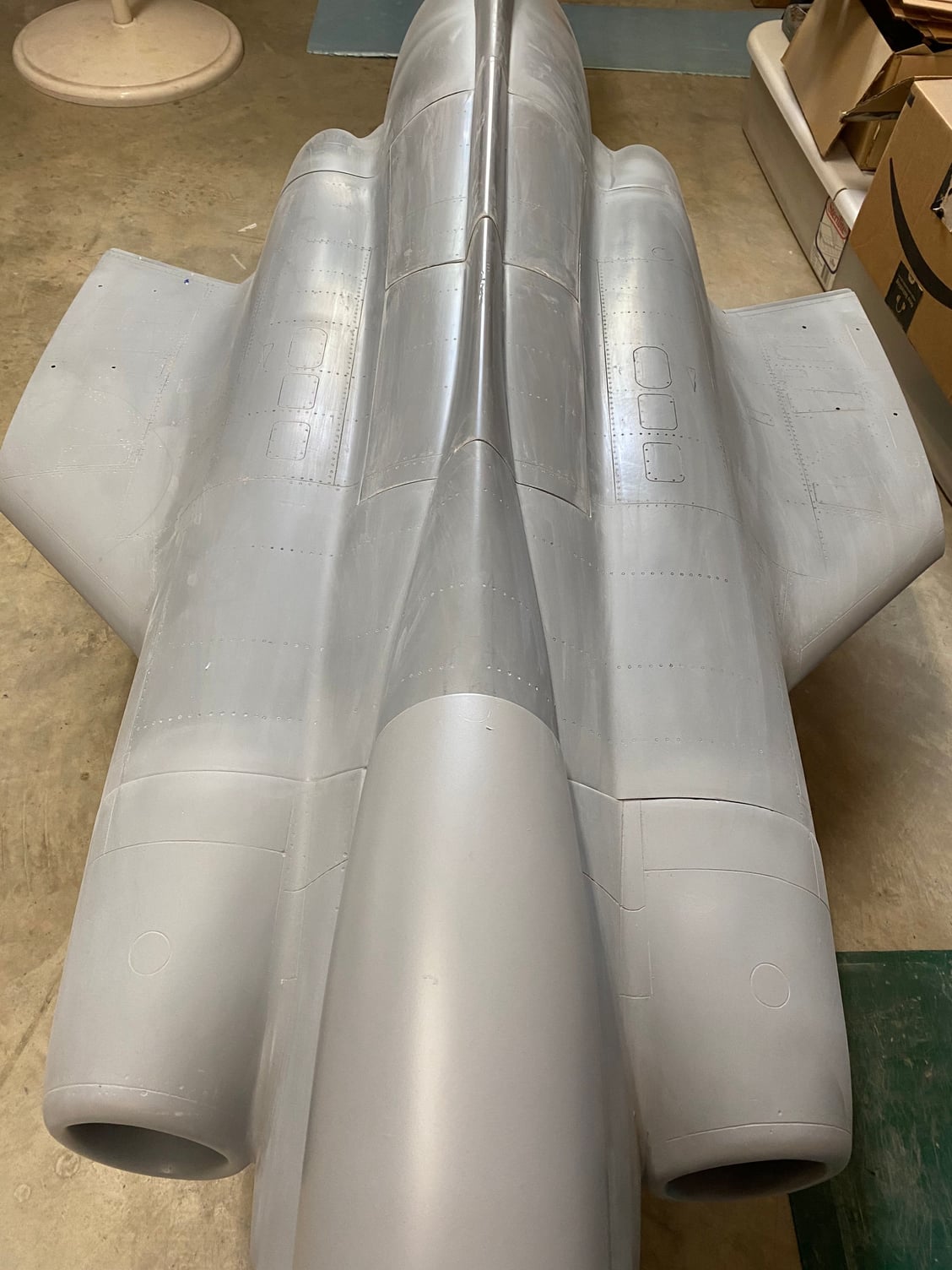
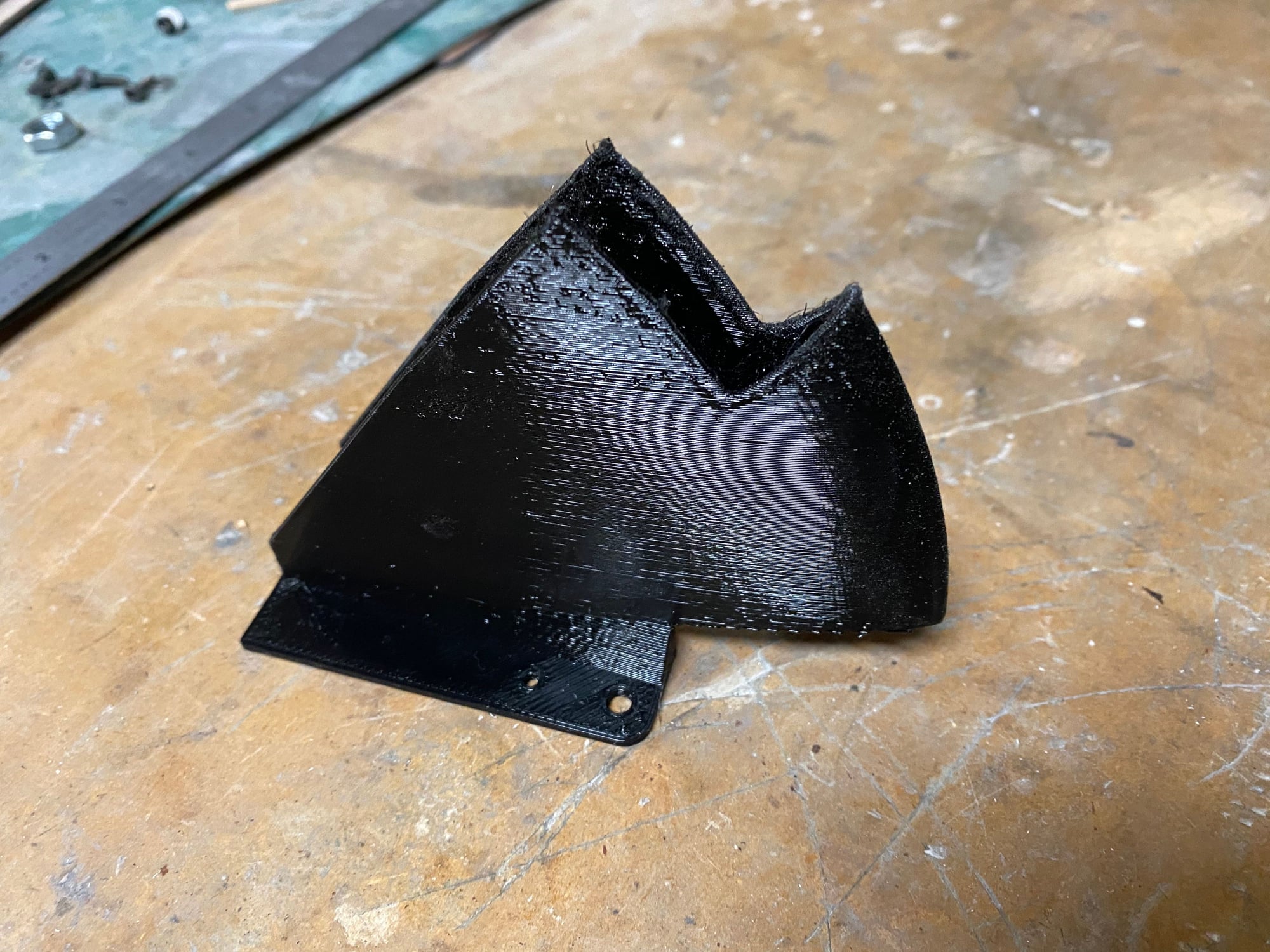
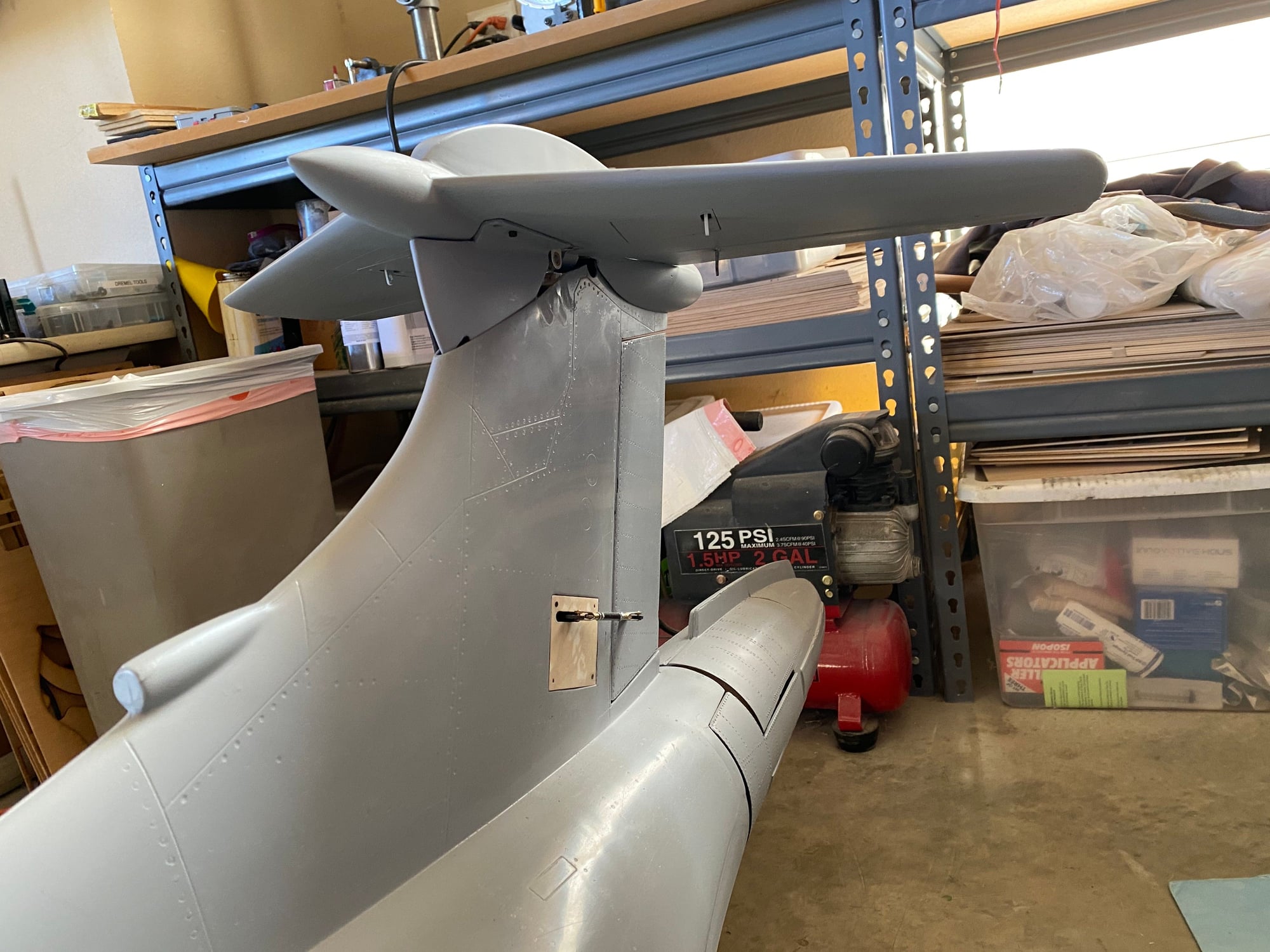
To close the gap between the fin and the tailplane, I 3D printed a shroud that is attached to the bottom of the tailplane pivot plate, and it rotates down inside the fin. The cutout at the leading edge is to clear the tailplane push rod when full up-elevator is applied. Once 3D printed, it was given a layer of glass/ epoxy before being rubbed down and primed.
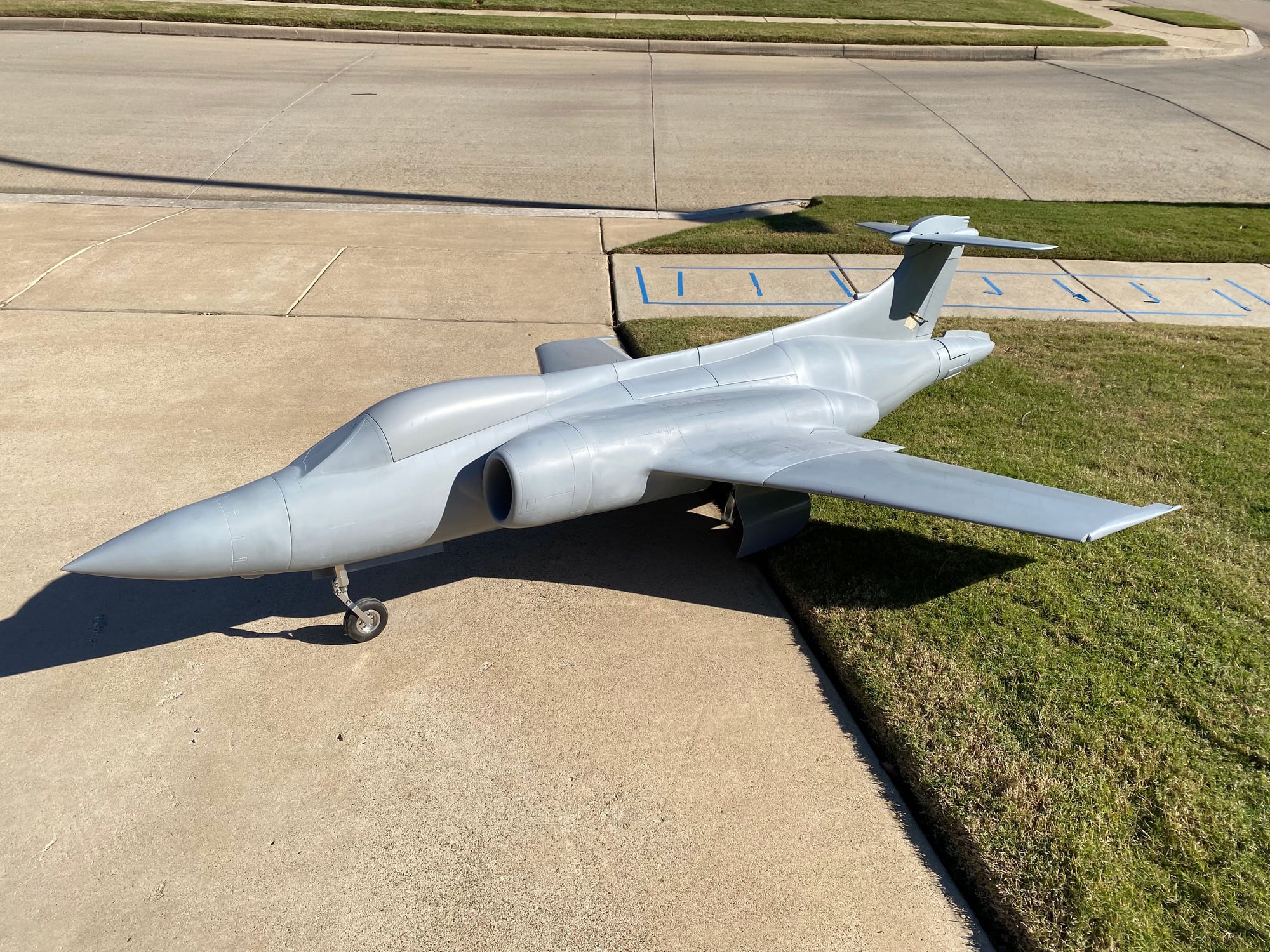
With it essentially complete less the engines and pipes, I took the opportunity to weigh it and check the c.g. As weighed, it came out at 41.75lb and the c.g. is tracking nicely. I'm hoping that I will need minimal nose ballast. With a 4lb weight added at around the location for the engines, I may be able to get away with around 8oz of ballast. Fingers crossed that there are no surprises in store.
I've started to lay out a balsa chuck-glider in order to confirm my c.g location ahead of first flight.
A photo of the Bucc catching some sun today.
Paul
To close the gap between the fin and the tailplane, I 3D printed a shroud that is attached to the bottom of the tailplane pivot plate, and it rotates down inside the fin. The cutout at the leading edge is to clear the tailplane push rod when full up-elevator is applied. Once 3D printed, it was given a layer of glass/ epoxy before being rubbed down and primed.
With it essentially complete less the engines and pipes, I took the opportunity to weigh it and check the c.g. As weighed, it came out at 41.75lb and the c.g. is tracking nicely. I'm hoping that I will need minimal nose ballast. With a 4lb weight added at around the location for the engines, I may be able to get away with around 8oz of ballast. Fingers crossed that there are no surprises in store.
I've started to lay out a balsa chuck-glider in order to confirm my c.g location ahead of first flight.
A photo of the Bucc catching some sun today.
Paul


The following users liked this post:
grbaker (11-02-2020)
 11-02-2020, 01:42 PM
#491

Impressive work.
Regards,
Regards,
11-02-2020, 02:25 PM
#492
Pat,
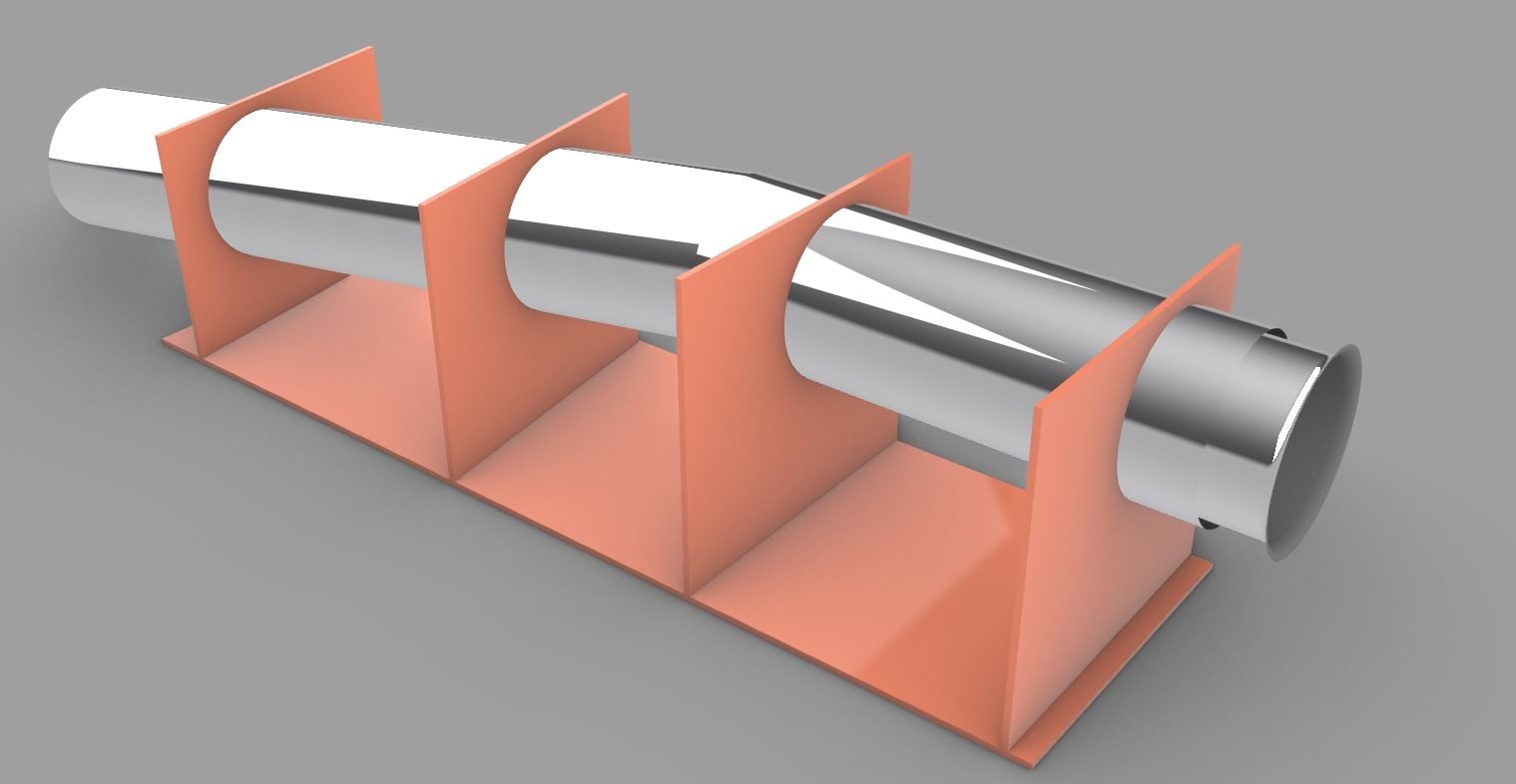
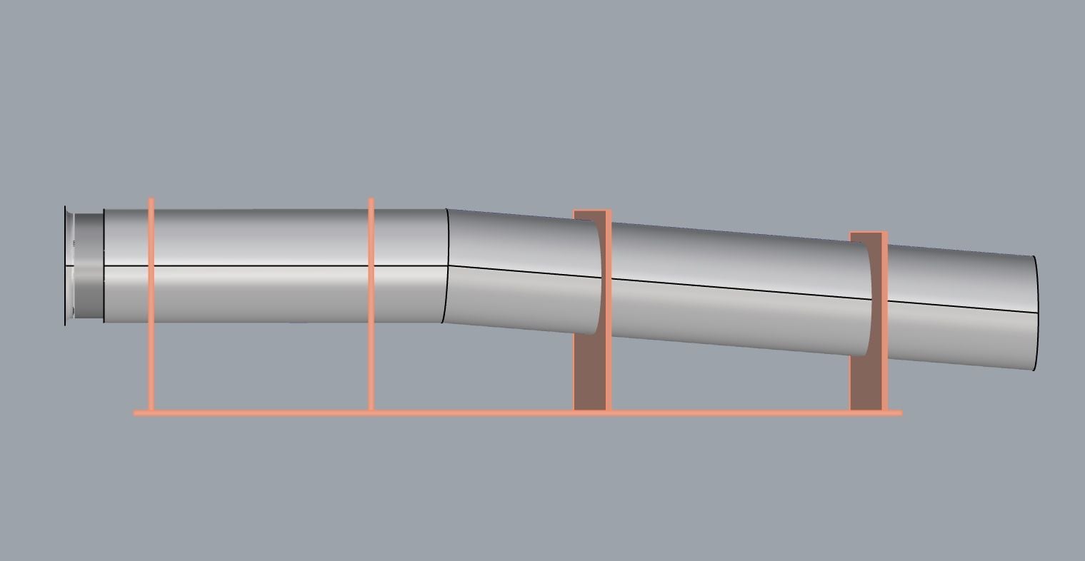
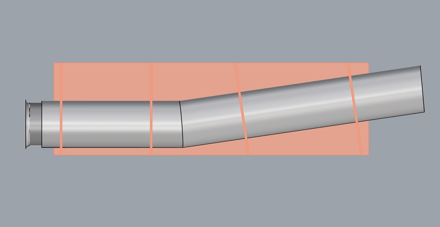
I showed Joey the pipe jig earlier today, but he doesn't have to correct formers or bellmouth. He's also never made a (deliberately) bent pipe either, so that was another area of concern.
Hiep used to make the Tam pipes. They are real works of art, so I'm hopeful that he can make them.
Paul

 11-04-2020, 12:09 AM
#497
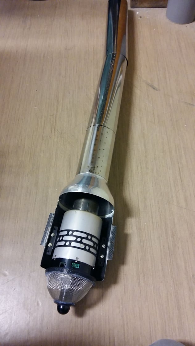
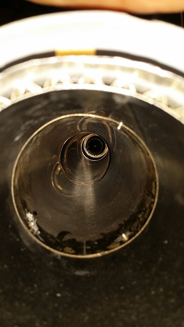
I put two old conical (~delta 10mm) CARF Mig 29 thrust tubes together. They are not welded, mechanical fixed together with a clips system and springs.
Works fine.
regards Martin
Works fine.
regards Martin
Last edited by MaHo; 11-04-2020 at 12:15 AM.
11-04-2020, 11:59 AM
#498

Edit: on re-reading, sounds like you used two MiG-29 pipes, not that this pipe was installed in a MiG-29...
 11-05-2020, 12:03 AM
#500
Not sure I'm following. Did you drastically change the turbine installation/location in that kit? The nacelles in the MiG-29 are about as straight as it gets and the CARF MiG puts the engines much further to the rear than those pipes would indicate.
Edit: on re-reading, sounds like you used two MiG-29 pipes, not that this pipe was installed in a MiG-29...
Edit: on re-reading, sounds like you used two MiG-29 pipes, not that this pipe was installed in a MiG-29...
My Mig 29 will use other stuff right.
regards Martin
Last edited by MaHo; 11-05-2020 at 12:09 AM.

