


1/7 Scale Blackburn Buccaneer All Composite Scratch Build
 12-11-2020, 05:30 PM
#501


Just over a month since the last update. Visible progress has slowed, but still some very important issues have been resolved.
All the control surfaces have been connected, adjusted and initial throws have been set, based on the 'it looks about right' principle. More importantly, I have managed to make all my original servos and linkages LTMA compliant with regard to servo torque. I had feared that I would have to replace various servos, but after seeing how little servo travel I was using I back-calculated the servo arm radius needed, and managed to ensure that both the tailplane and ailerons came within requirements. That saved a huge amount of work in the wings by avoiding to have to remake the integrated servo mounts.
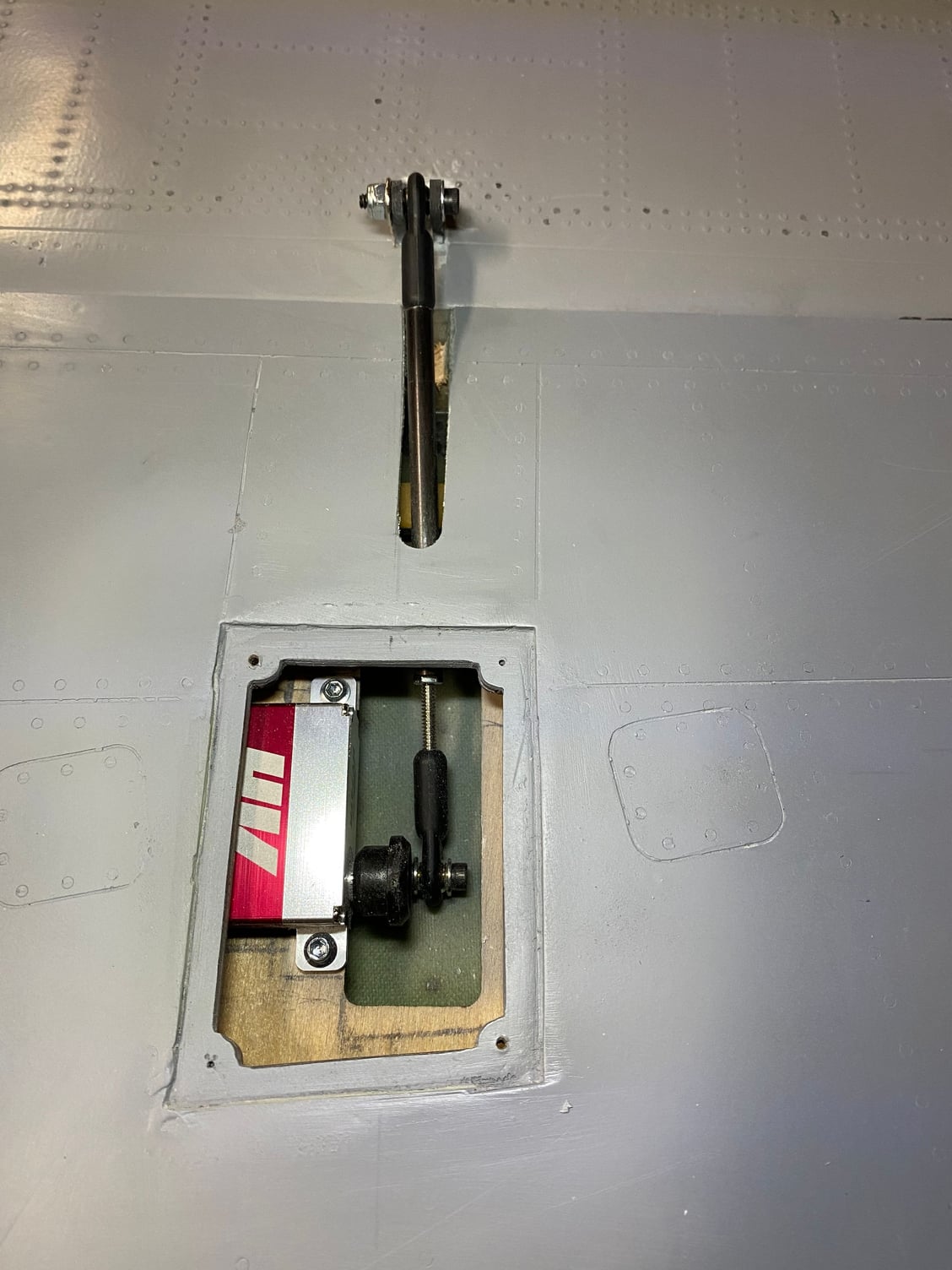
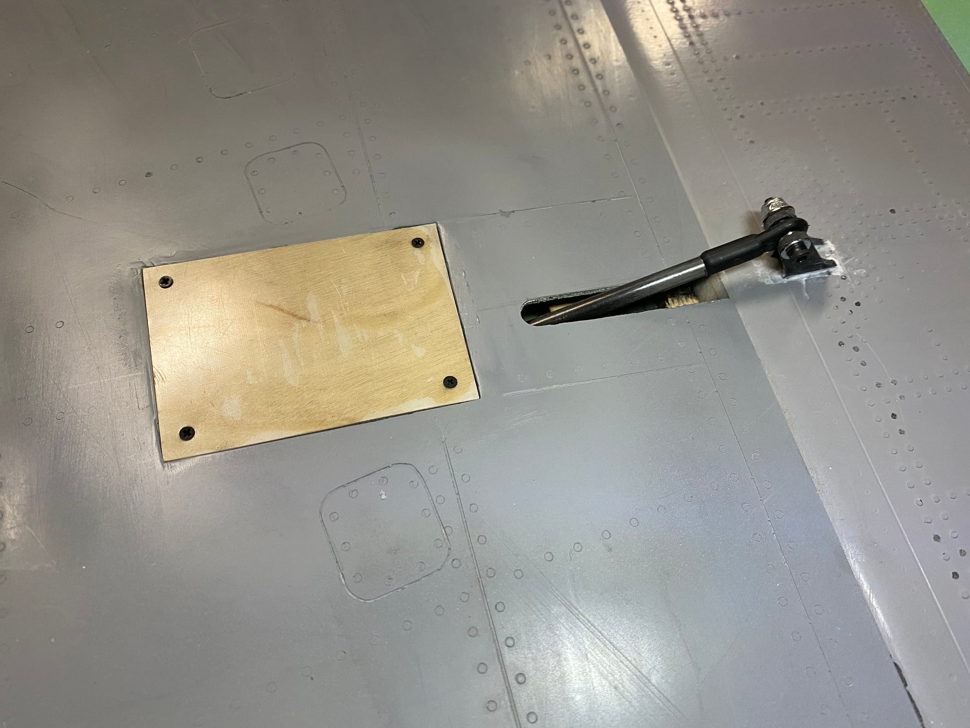
For the ailerons, a happy by-product of reducing the servo arm radius was that I could revert to my original plan to have a semi-scale control actuation layout, with the pushrod exiting out of the lower wing skin. Once they were all installed, I added in a second control horn to support the ball-link.
All the control surfaces have been connected, adjusted and initial throws have been set, based on the 'it looks about right' principle. More importantly, I have managed to make all my original servos and linkages LTMA compliant with regard to servo torque. I had feared that I would have to replace various servos, but after seeing how little servo travel I was using I back-calculated the servo arm radius needed, and managed to ensure that both the tailplane and ailerons came within requirements. That saved a huge amount of work in the wings by avoiding to have to remake the integrated servo mounts.
For the ailerons, a happy by-product of reducing the servo arm radius was that I could revert to my original plan to have a semi-scale control actuation layout, with the pushrod exiting out of the lower wing skin. Once they were all installed, I added in a second control horn to support the ball-link.
Last edited by JSF-TC; 12-11-2020 at 06:09 PM.

The following users liked this post:
grbaker (12-12-2020)
12-11-2020, 05:34 PM
#502
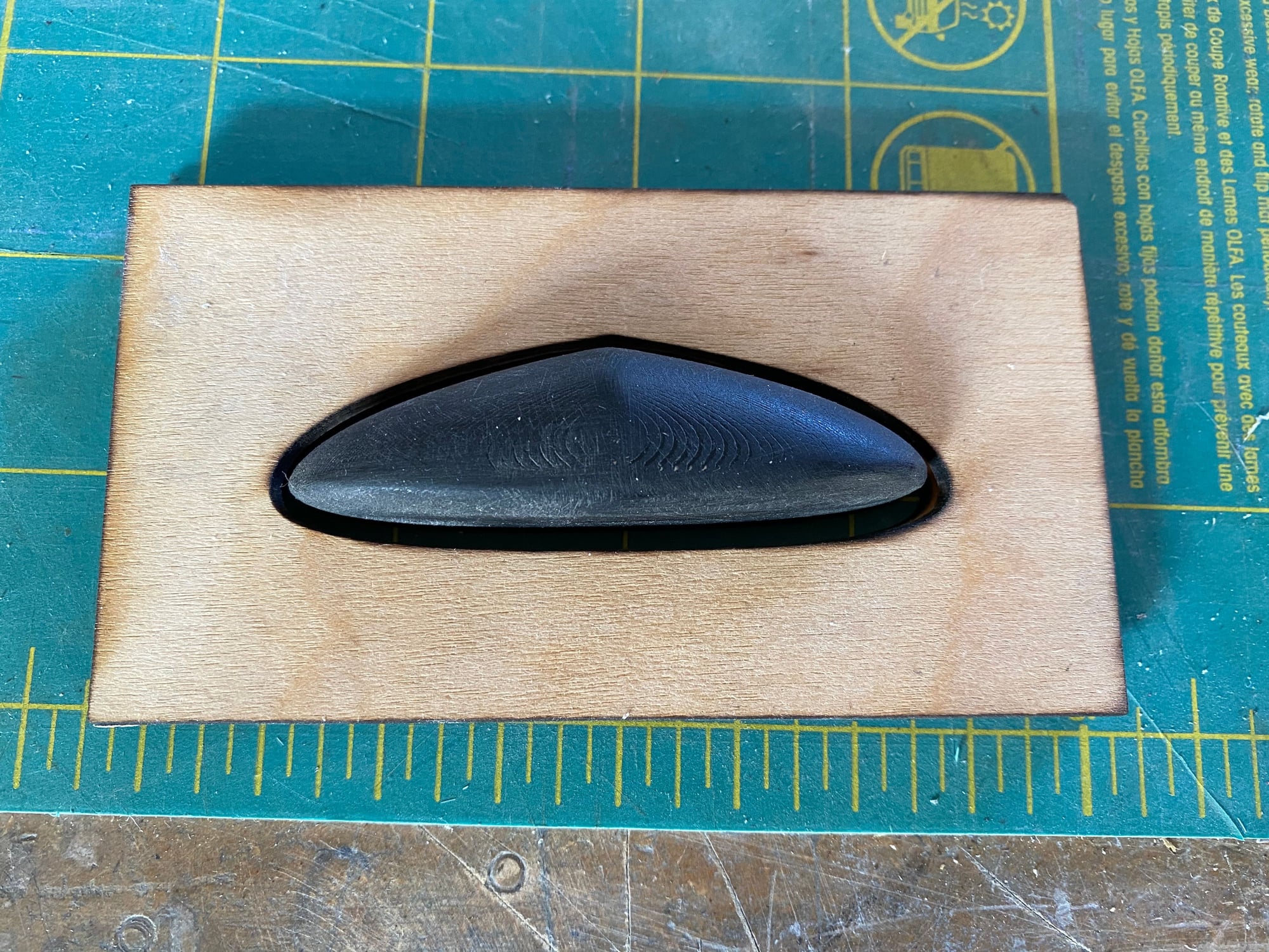
Next up was to make the wingtip light covers. A simple plug was designed and 3D printed, with it being 0.5mm under-size to allow for the thickness. I then laser cut 2 matching frames with a 2mm clearance all around.
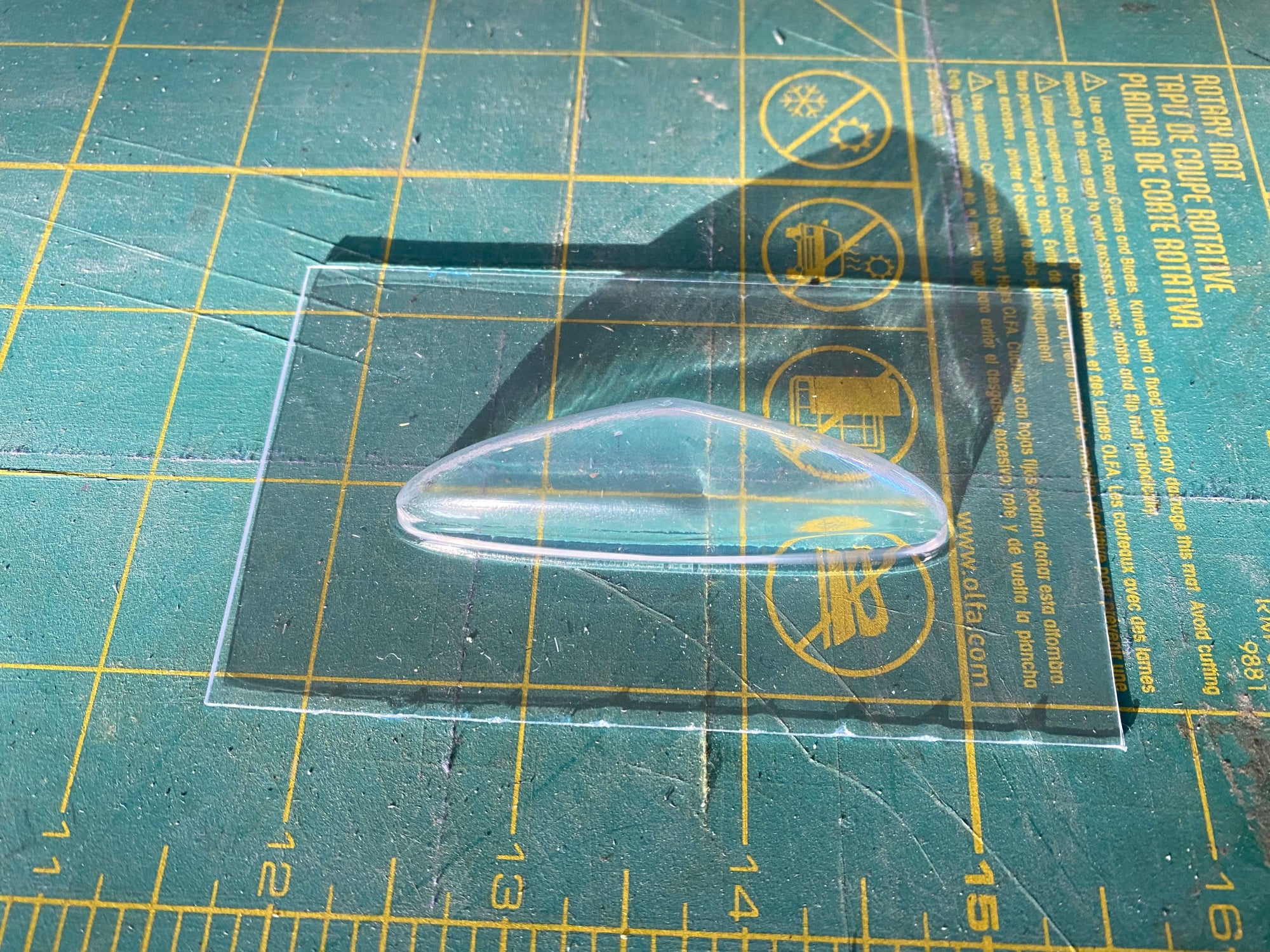
These frames were used to clamp a sheet of 0.030" clear PETG which was then heated in the oven until soft and then simply plunged over the plug. After a couple of attempts I ended up with an acceptable set of clear covers. They were trimmed and installed with canopy glue. They will be removed during finishing to install the nav lights.
Paul
The following users liked this post:
grbaker (12-12-2020)
12-11-2020, 06:08 PM
#503
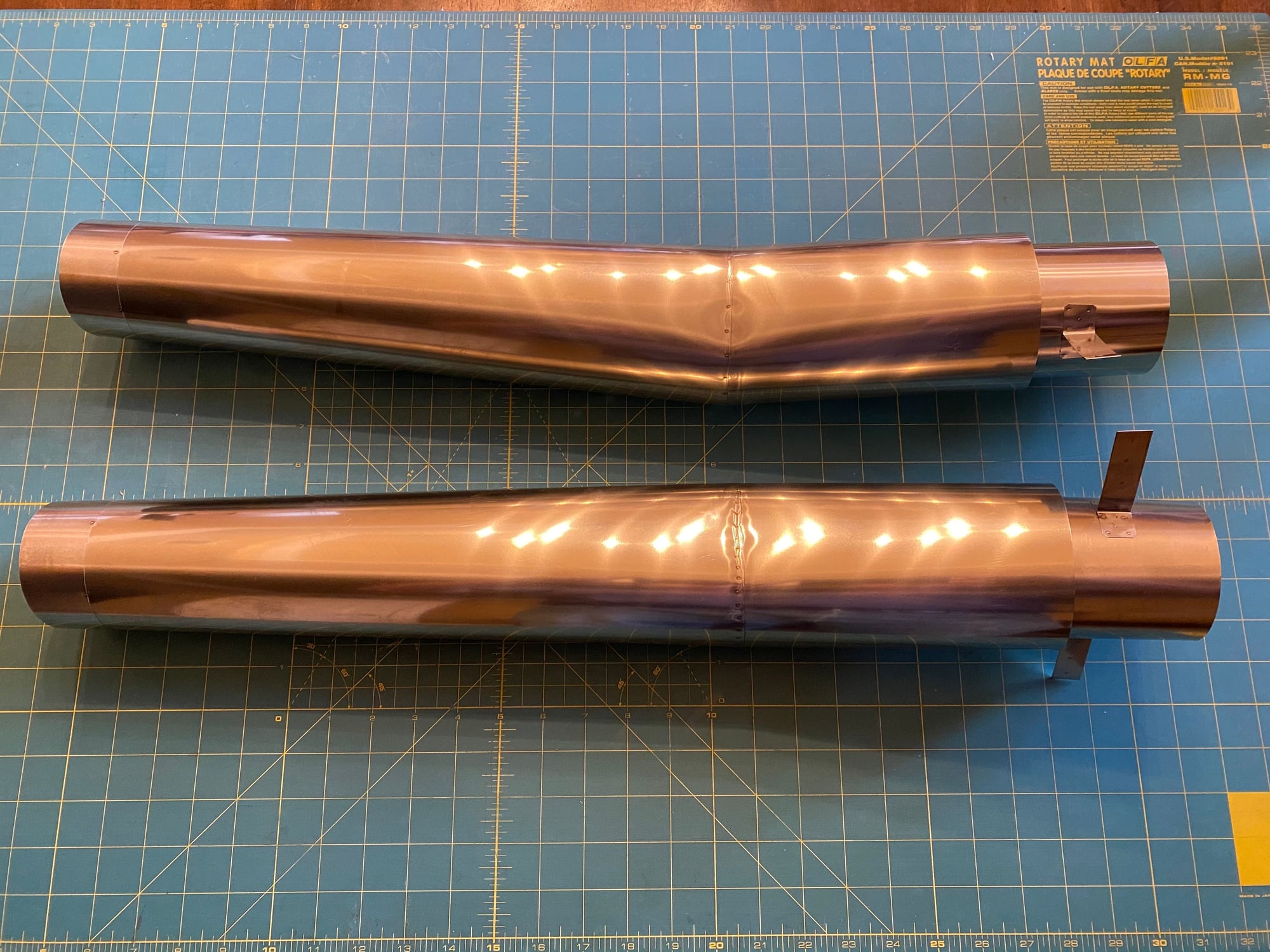
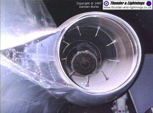
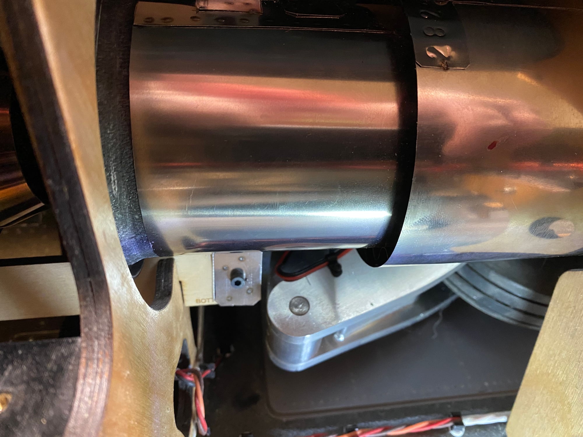
By far the biggest task of the last few months has been to complete the exhaust pipes.
The basic concept as shown previously was a pipe with a single bend in it. After a number of inquiries to a number of well-know pipe builders I was starting to loose confidence. Everyone said that the pipe diameter was too small and the cooling gap to the outer pipe was too small, and that I would have to change it.
Changing the pipe diameter would require major surgery on the model and was considered not an option. The inner pipe met the minimum spec in the engine manual and previous inputs suggested that the cooling gap, albeit small, was adequate.
I then contacted Gary at Jet-Tech and struck up an extremely productive conversation. Gary was super helpful in providing comments on how the original design couldn't be made, but at the same time providing suggestions on what to change. After a couple of weeks with me incorporating his suggestions into the design, we progressively started to develop a workable solution, both from a performance perspective and one that could be made.
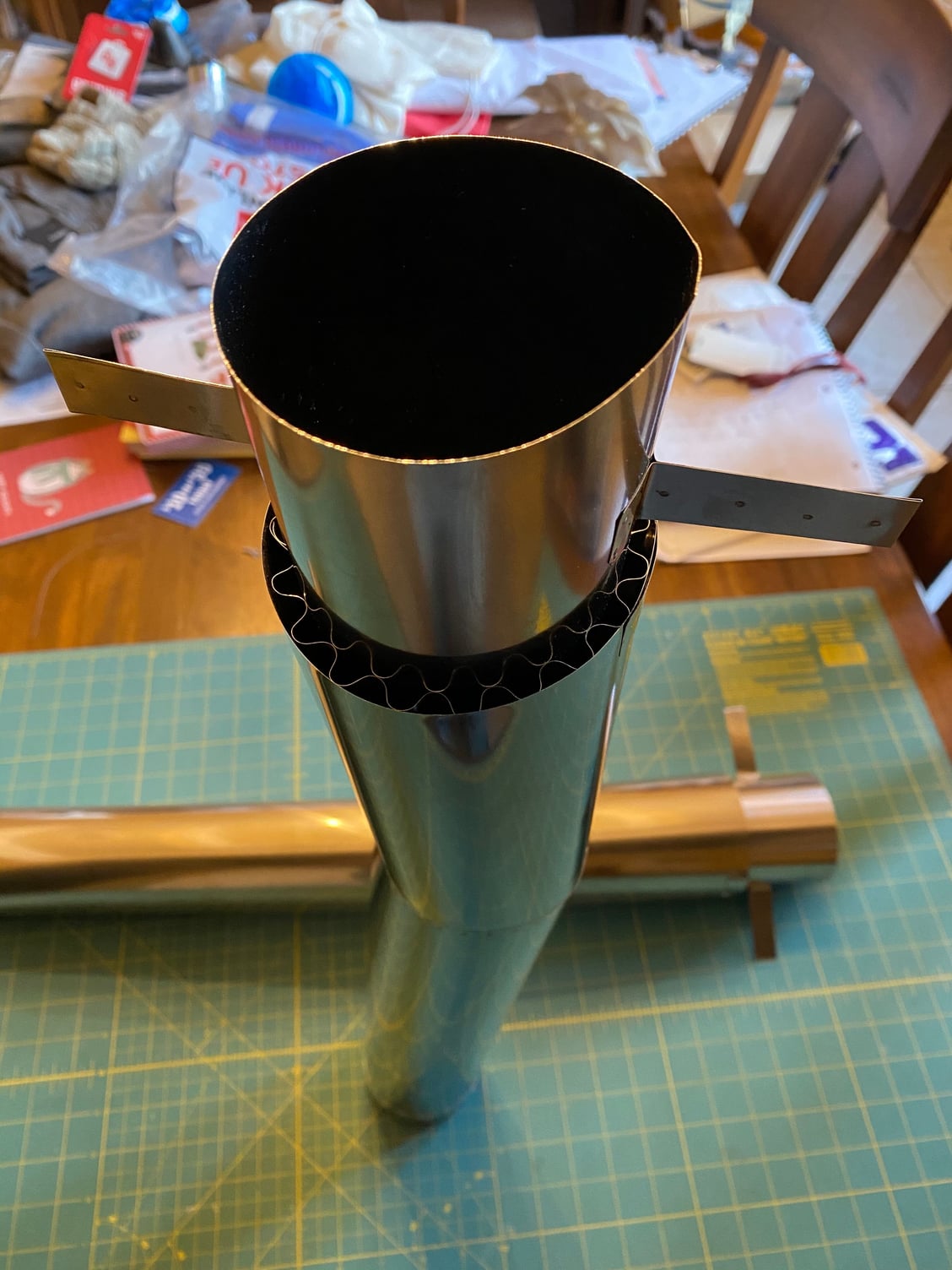
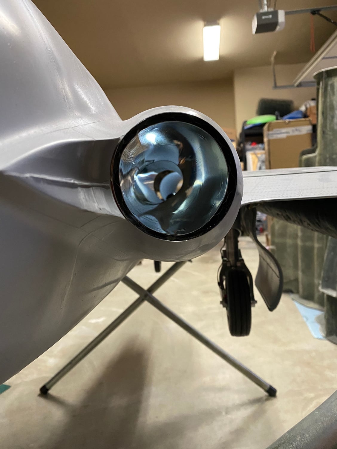
What we settled on was a tapered pipe that reduced down to the minimum exit area, but started larger and with a constant area reduction taper rate. In order to clear the main gear when retracted we couldn't keep a simple circular cross section, so it changed from initially circular to an oval cross section at the angle break and then a progressive change back to a circle at the exit. The outer pipe also followed the same approach, with the pipe gap adjusted to give an almost constant cross sectional area for the cooling flow too.
Once the design was set, it only took Gary a week to make both pipes. They showed up today and they are a true work of art. And the best part is that they dropped straight in to the model and fitted perfectly.
I have to make the bell-mouths as Gary didn't have a size that would fit, so I plan to 3D print a mold and layup a pair of simple composite inlet lips. I may consider going to a fully ducted bypass solution after first flight, but a simple lip will suffice for now.
Once my engines show up I can finalize the engine mounts which will also serve as the forward pipe mounts and get them installed.
A big thank you to Gary at Jet Tech for helping out with such a critical part, especially considering one of his final comments which I hope he doesn't mind me posting; "I have to admit that these pipes were a much bigger challenge than a custom bifurcated pipe."
And just a comparison between the full-scale and the model:
Paul
The basic concept as shown previously was a pipe with a single bend in it. After a number of inquiries to a number of well-know pipe builders I was starting to loose confidence. Everyone said that the pipe diameter was too small and the cooling gap to the outer pipe was too small, and that I would have to change it.
Changing the pipe diameter would require major surgery on the model and was considered not an option. The inner pipe met the minimum spec in the engine manual and previous inputs suggested that the cooling gap, albeit small, was adequate.
I then contacted Gary at Jet-Tech and struck up an extremely productive conversation. Gary was super helpful in providing comments on how the original design couldn't be made, but at the same time providing suggestions on what to change. After a couple of weeks with me incorporating his suggestions into the design, we progressively started to develop a workable solution, both from a performance perspective and one that could be made.
What we settled on was a tapered pipe that reduced down to the minimum exit area, but started larger and with a constant area reduction taper rate. In order to clear the main gear when retracted we couldn't keep a simple circular cross section, so it changed from initially circular to an oval cross section at the angle break and then a progressive change back to a circle at the exit. The outer pipe also followed the same approach, with the pipe gap adjusted to give an almost constant cross sectional area for the cooling flow too.
Once the design was set, it only took Gary a week to make both pipes. They showed up today and they are a true work of art. And the best part is that they dropped straight in to the model and fitted perfectly.
I have to make the bell-mouths as Gary didn't have a size that would fit, so I plan to 3D print a mold and layup a pair of simple composite inlet lips. I may consider going to a fully ducted bypass solution after first flight, but a simple lip will suffice for now.
Once my engines show up I can finalize the engine mounts which will also serve as the forward pipe mounts and get them installed.
A big thank you to Gary at Jet Tech for helping out with such a critical part, especially considering one of his final comments which I hope he doesn't mind me posting; "I have to admit that these pipes were a much bigger challenge than a custom bifurcated pipe."
And just a comparison between the full-scale and the model:
Paul
The following users liked this post:
grbaker (12-12-2020)
 12-12-2020, 06:20 AM
#506
Dave,
Hopefully the outer pipe will do its job and keep the heat from radiating into the fuselage, but yes, I have the space to wrap that area with insulation if needed.
Now, if only USPS could deliver my motors, I'd have plenty of work to do .
.
Paul
Hopefully the outer pipe will do its job and keep the heat from radiating into the fuselage, but yes, I have the space to wrap that area with insulation if needed.
Now, if only USPS could deliver my motors, I'd have plenty of work to do
.Paul
12-28-2020, 05:52 PM
#508
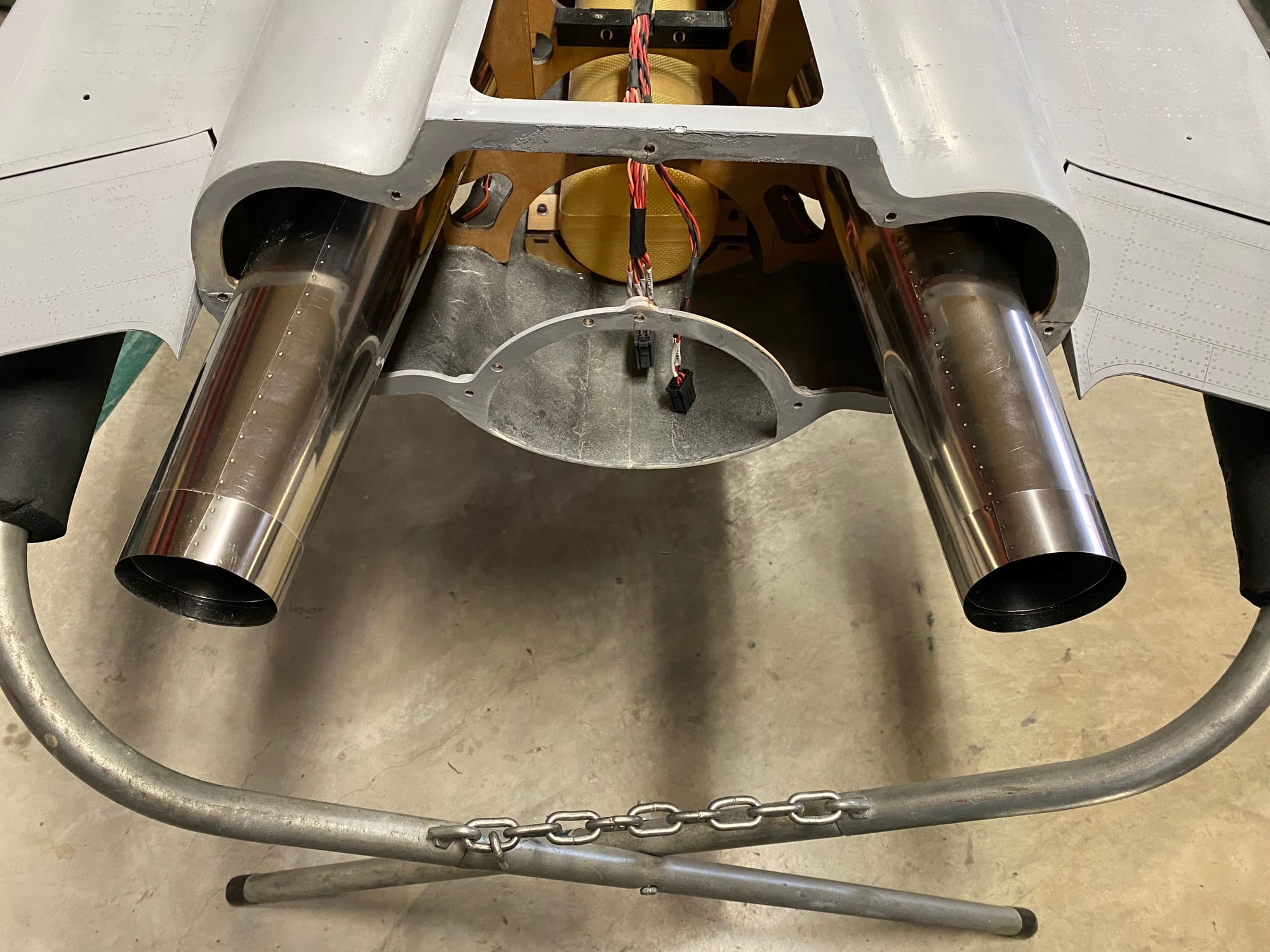
As standard bellmouths wouldn't fit the pipes. I laid up some composite carbon ones. I 3D printed a mold which was sanded down and coated with Duratec and then sanded/ polished to give a smooth finish. Glass and carbon was then cut out and laid up on the mold. I didn't bother to vacuum bag these given the shape, just using a simple wet layup. Once cured, they were trimmed and popped off the mold. They were designed to fit inside the pipe and then have a 180deg lip that was big enough to just fit between then engine mount rails, and they were retained onto the front of the pipe with a couple of 2mm bolts.
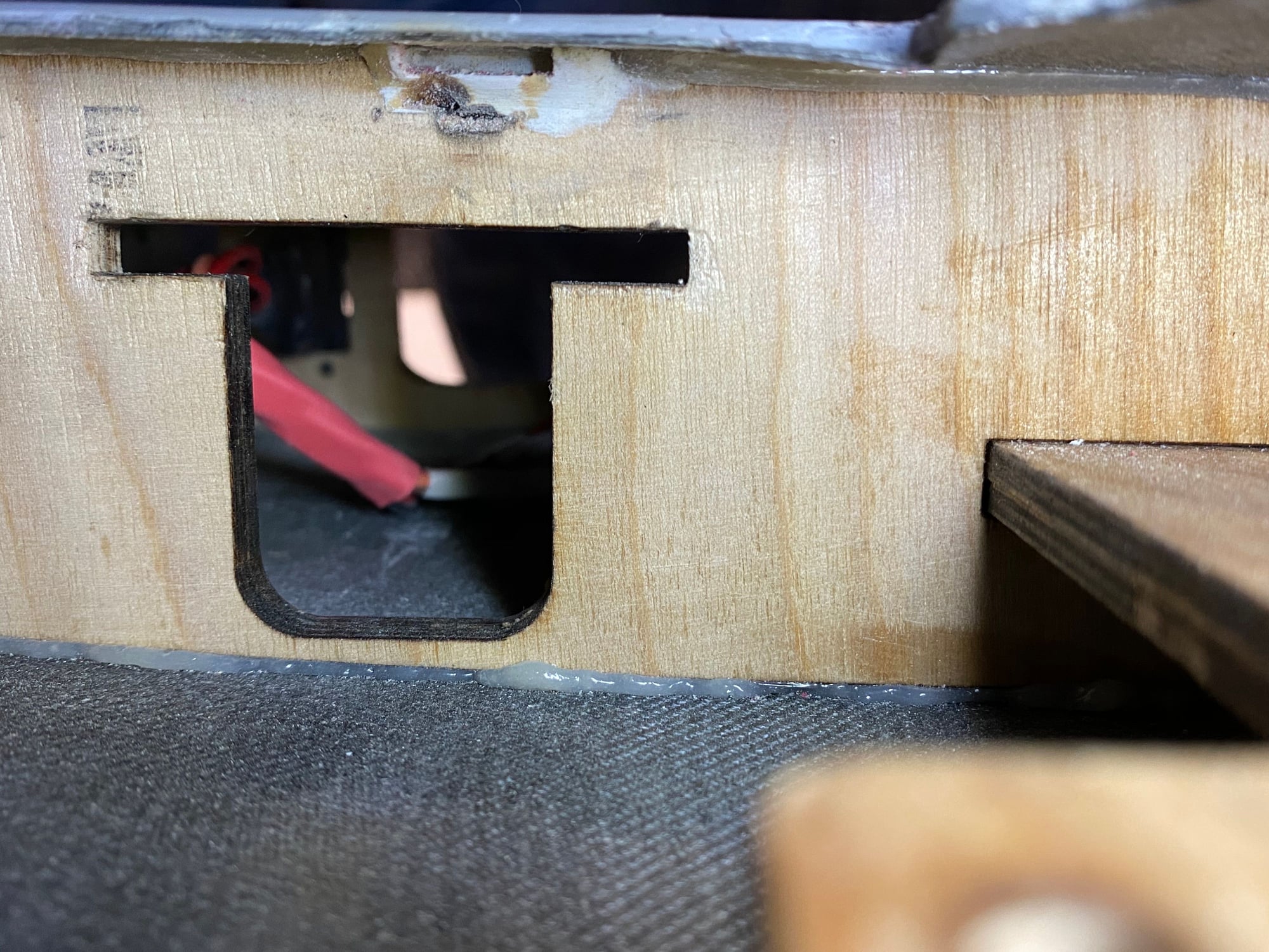
The only problem I had installing the pipes was in the placement of the mounting tabs. I had provided a location to Gary, and he installed them exactly as requested, but I had not done a full CAD assessment, and it bit me - the tabs clashed with the gear when the gear was retracted. The simple solution was to cut off the tabs and re-mount them in a more forward location. This was done with the help of Joey at JT Hobbies. The engine mounting rails were extended aft to provide a location to bold the pipe mounting tabs and M3 captive nuts inserted into the rails for both the engine mount and the pipe. The mounting holes were cut with a hole punch for both pipes and the bellmouth bolts.

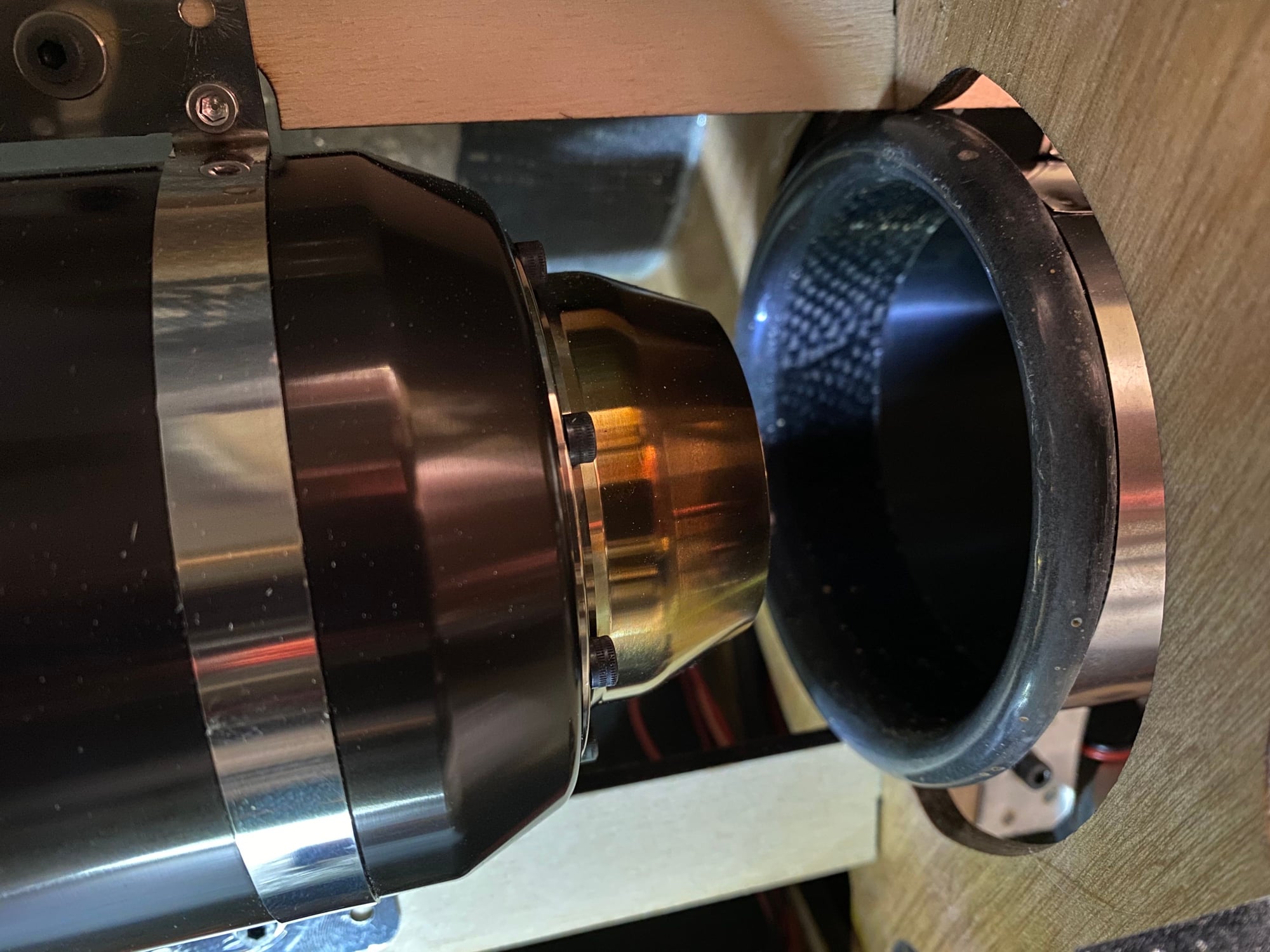
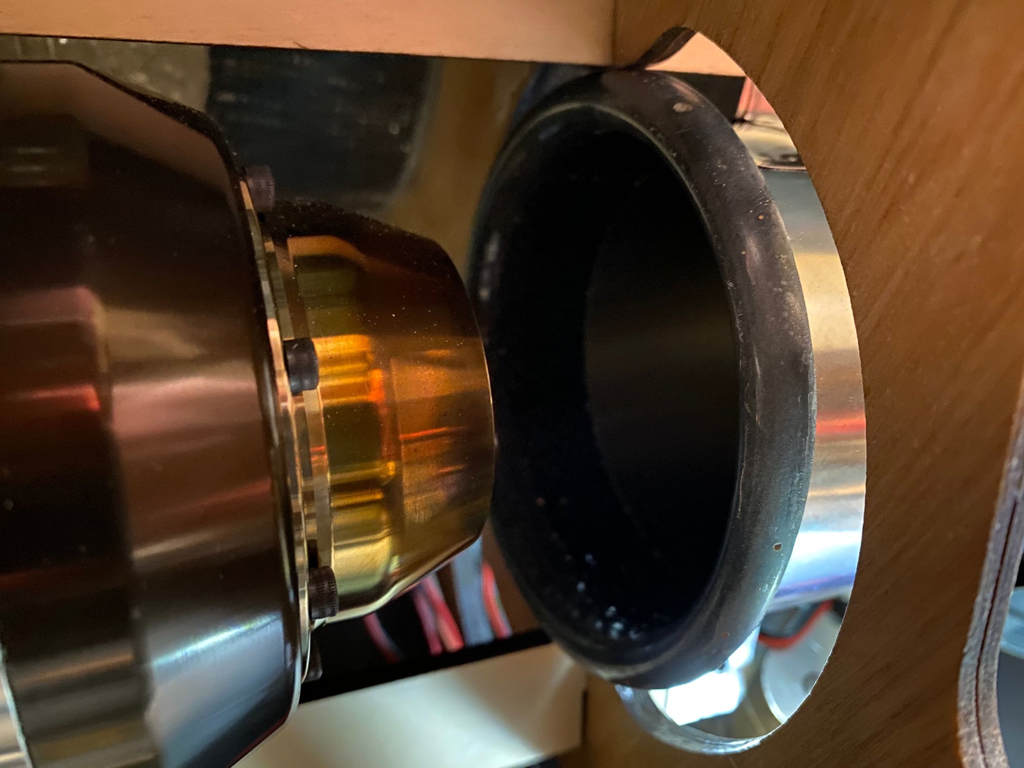
The only problem I had installing the pipes was in the placement of the mounting tabs. I had provided a location to Gary, and he installed them exactly as requested, but I had not done a full CAD assessment, and it bit me - the tabs clashed with the gear when the gear was retracted. The simple solution was to cut off the tabs and re-mount them in a more forward location. This was done with the help of Joey at JT Hobbies. The engine mounting rails were extended aft to provide a location to bold the pipe mounting tabs and M3 captive nuts inserted into the rails for both the engine mount and the pipe. The mounting holes were cut with a hole punch for both pipes and the bellmouth bolts.
12-28-2020, 06:00 PM
#509
My 2 Merlin 100 engines showed up just before Christmas, following an extended 2 day trip that turned into 2 weeks. They are beautiful engines, as to be expected, and using the measured mounting strap dimensions I cut out the engine mounting rails from 1/4" 5-ply. The motors dropped right into place and could be installed from the front of the forward fuselage section. They almost look lost inside the fuselage.
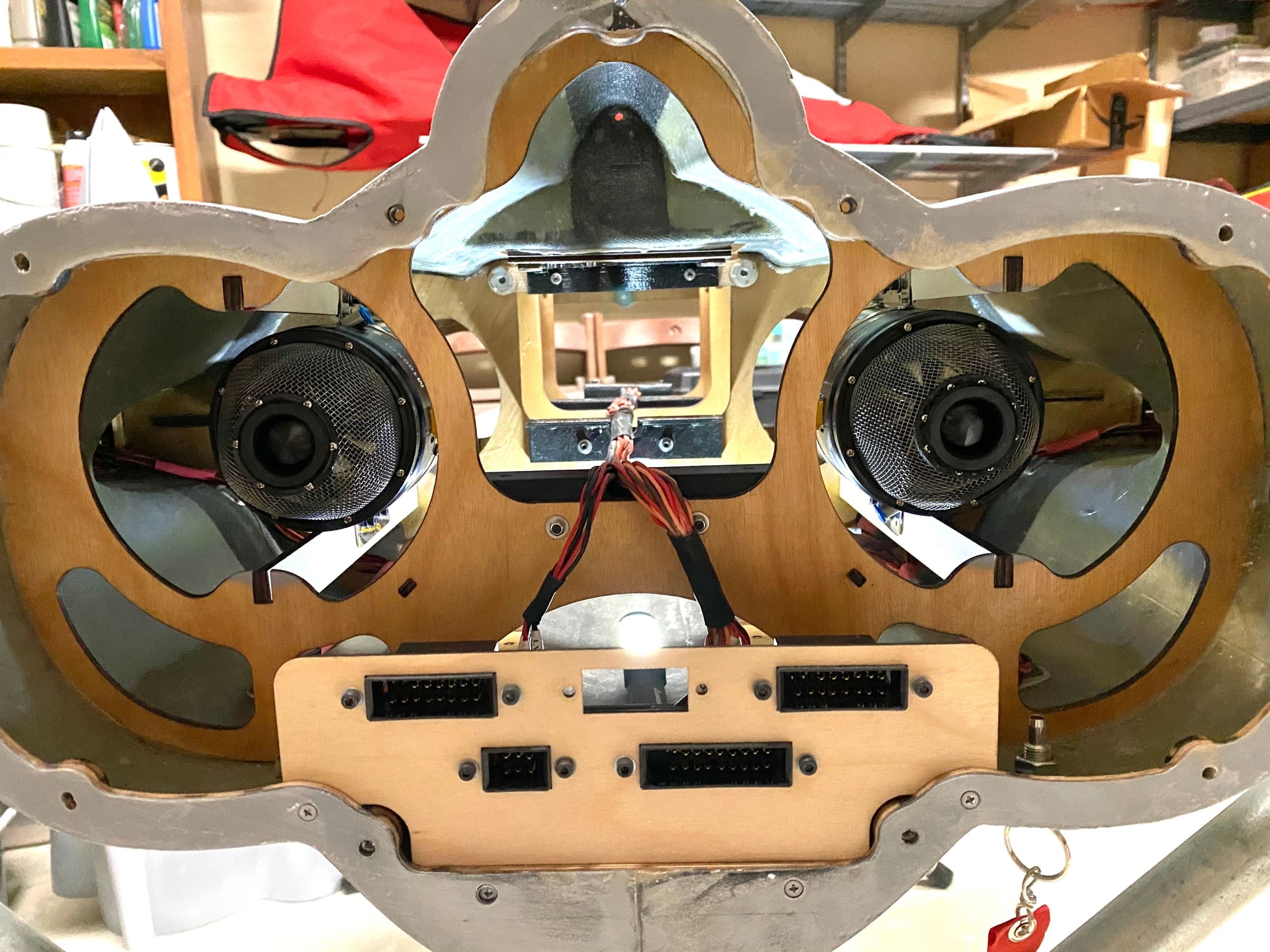
The arrival of the engines also allowed me to design and 3D print mounting blocks for the fuel pumps and install them on the center tray and complete the fuel lines. A few hours were spent making the ECU to motor and ECU to fuel pump harnesses that completed the wiring installation too. I had to change connectors on 2 harnesses, as Jets Munts have switched from Multiplex to XT30 style connectors.
The arrival of the engines also allowed me to design and 3D print mounting blocks for the fuel pumps and install them on the center tray and complete the fuel lines. A few hours were spent making the ECU to motor and ECU to fuel pump harnesses that completed the wiring installation too. I had to change connectors on 2 harnesses, as Jets Munts have switched from Multiplex to XT30 style connectors.

 12-28-2020, 06:07 PM
#511
Doing clearance checks between the gear and the pipes, I decided to move the brake wiring from the inside to the outside of the gear to move the wiring away from the hot pipe and to also gain a little bit more clearance.
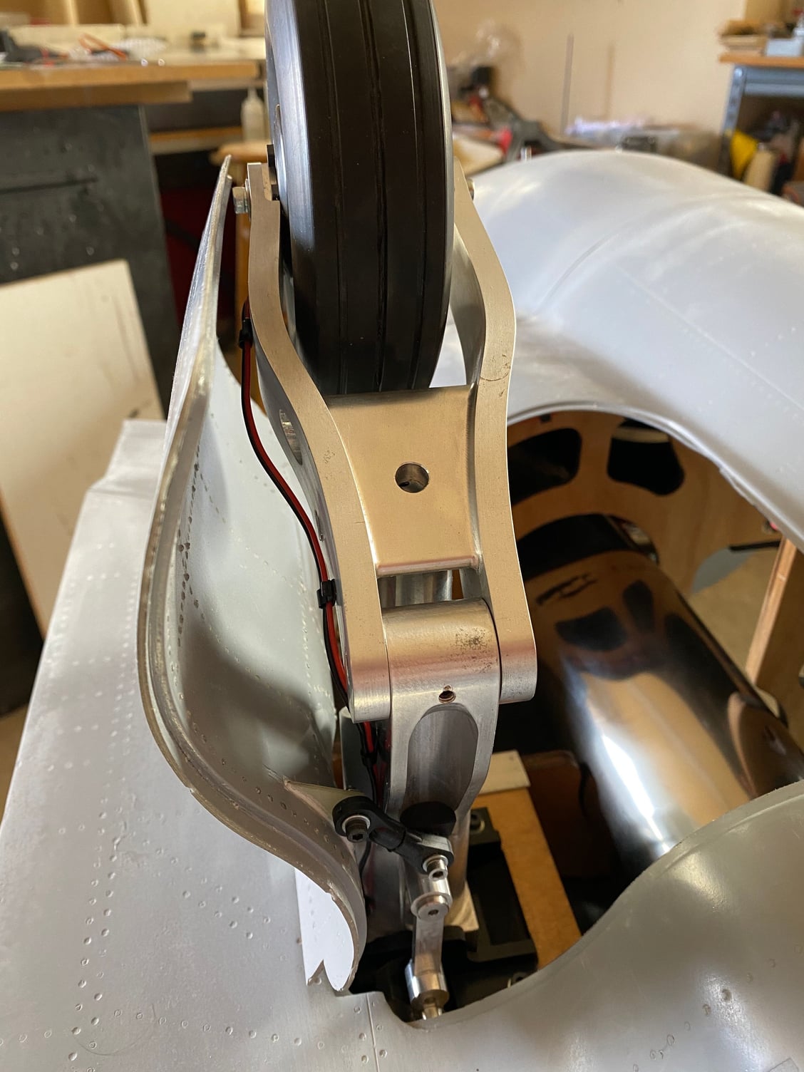
In doing this, I stripped down each main gear assembly and added lubrication before a final re-assembly with blue Locktite. As I was re-assembling the gear in the fuselage, I noticed that the thread on one of the main gear door hinge screws was stripped. As I withdrew the pin, one of the hinge mount lugs fell off, forcing a full repair. As these were well Hysol'd in place this needed a subtle approach. The application of a hot 60W soldering iron to each hinge piece softened the epoxy sufficiently that a gently pull with a pair of pliers was all that was required to free both parts with no further damage. New parts were then simply glued back in place. IT turned out to be a much simpler repair then initially feared.
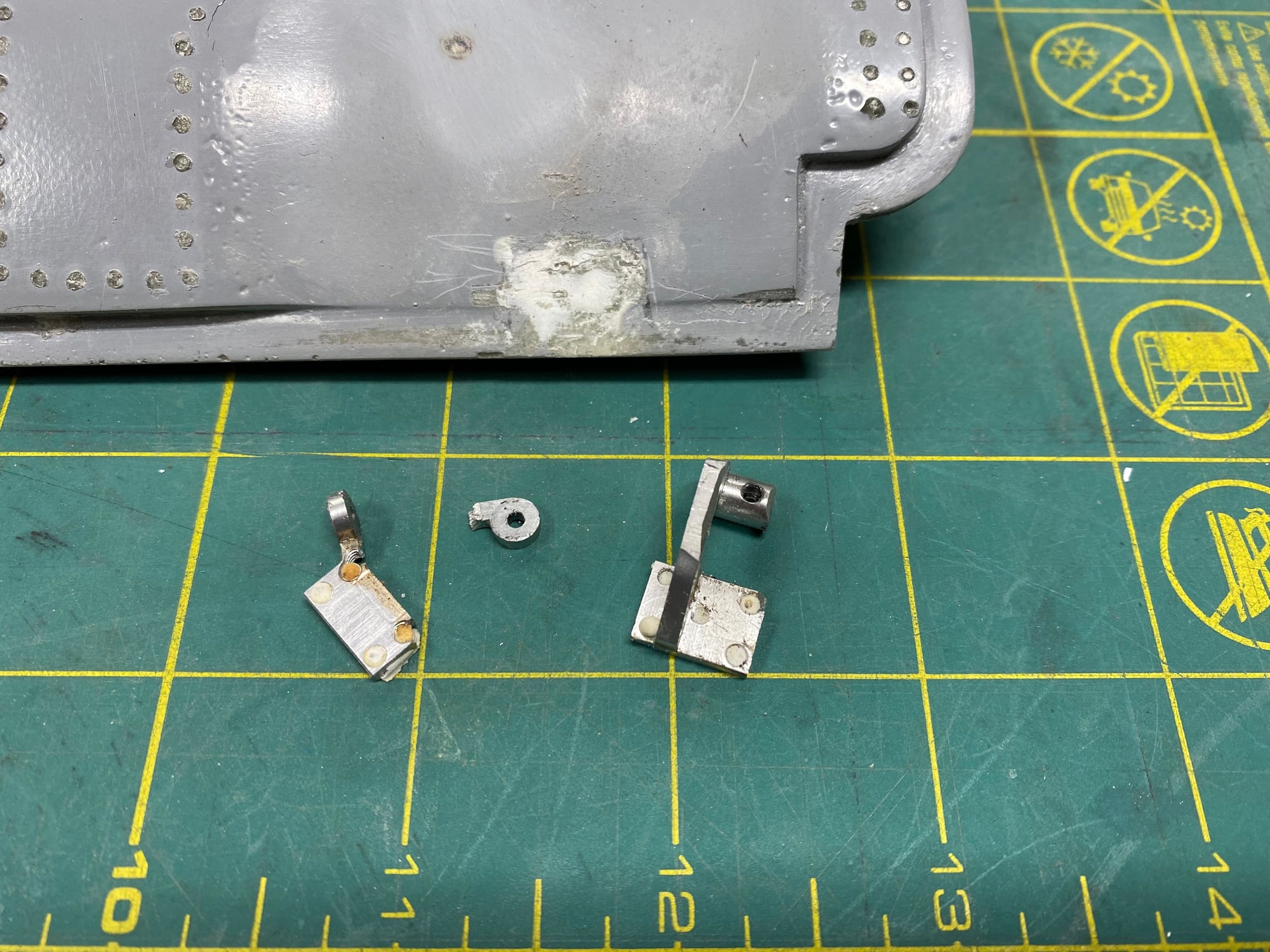
In doing this, I stripped down each main gear assembly and added lubrication before a final re-assembly with blue Locktite. As I was re-assembling the gear in the fuselage, I noticed that the thread on one of the main gear door hinge screws was stripped. As I withdrew the pin, one of the hinge mount lugs fell off, forcing a full repair. As these were well Hysol'd in place this needed a subtle approach. The application of a hot 60W soldering iron to each hinge piece softened the epoxy sufficiently that a gently pull with a pair of pliers was all that was required to free both parts with no further damage. New parts were then simply glued back in place. IT turned out to be a much simpler repair then initially feared.
Last edited by JSF-TC; 12-28-2020 at 06:34 PM.
12-28-2020, 06:28 PM
#512
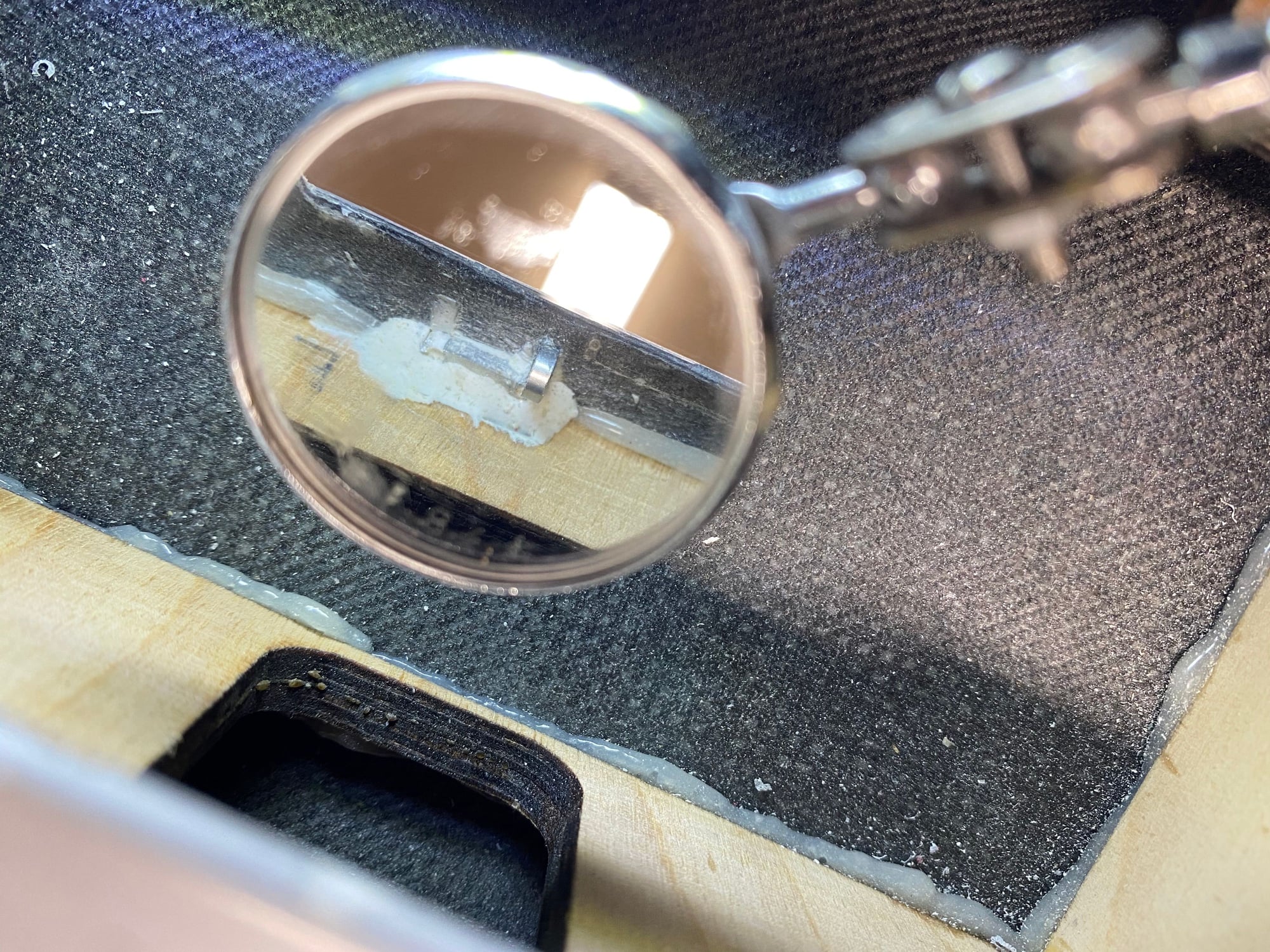
With the gear back in place and the fuel system installed and tubing completed it was time to add fuel for the first time. This went well with no leaks, so next up was initial engine runs.
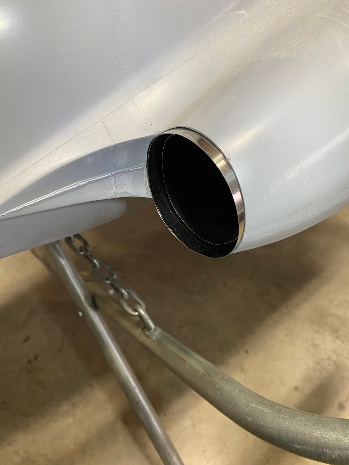
Each engine was run at idle for a few minutes and temperatures checked, particularly around the exhaust area where I was concerned about the fuselage getting hot. No concern was needed as the angle of the pipes worked well to keep the exhaust away from the fuselage and also beneath the speedbrake. The fuselage just above the engine exhaust was a little warm, but nothing to be concerned about so far. I can add some self-adhesive reflective insulation there if it gets too hot.
To complete a significant day, a low speed taxy test was performed. Both engines ran well together and no issues were seen with a simple taxy test. Brakes and steering checked out. It sounds great with a unique whistle to it.
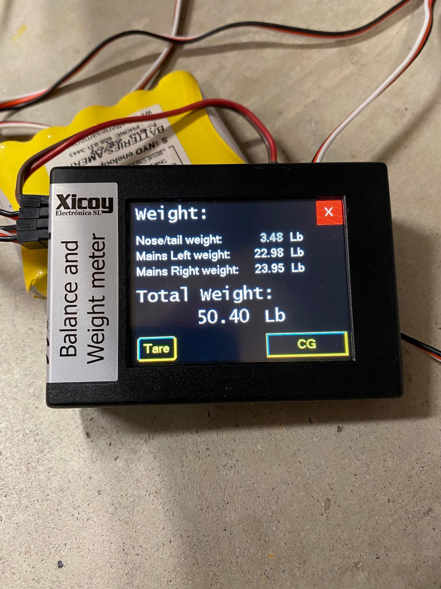
After draining all fuel except the air trap I checked the weight and c.g.
It came out to 50.4lb and balanced exactly mid-way between the forward and aft c.g. limits as defined in the full-scale maintenance manual without needing any ballast at all.
Next up will be a trip to our local field for some high power engine runs and some faster taxy testing. The local field is too small for a first flight but it will be a good checkout.
Each engine was run at idle for a few minutes and temperatures checked, particularly around the exhaust area where I was concerned about the fuselage getting hot. No concern was needed as the angle of the pipes worked well to keep the exhaust away from the fuselage and also beneath the speedbrake. The fuselage just above the engine exhaust was a little warm, but nothing to be concerned about so far. I can add some self-adhesive reflective insulation there if it gets too hot.
To complete a significant day, a low speed taxy test was performed. Both engines ran well together and no issues were seen with a simple taxy test. Brakes and steering checked out. It sounds great with a unique whistle to it.
After draining all fuel except the air trap I checked the weight and c.g.
It came out to 50.4lb and balanced exactly mid-way between the forward and aft c.g. limits as defined in the full-scale maintenance manual without needing any ballast at all.
Next up will be a trip to our local field for some high power engine runs and some faster taxy testing. The local field is too small for a first flight but it will be a good checkout.

 )
12-29-2020, 02:49 AM
)
12-29-2020, 02:49 AM
#514

Splendid work, good luck with the trials.
That said, a headsup !
I have a Merlin 100 ( a superb engine) in my Rotkoski Sabre. The duct is from my BVM f16 and BVM made a dual walled pipe for me.
The top of the fuselage was getting too warm, so out came the engine and jet pipe to install BVM ceramic blanket on the fuselage top, not the pipe itself. problem solved.
However, even though the engine was mounted as far aft on the duct rails as possible ( it has a short nozzle) there was some burning of the rear of the duct, which may well have burnt through completely after more flying with disastrous results.
The duct was repaired, mounting rails, and therefore the engine extended further aft. towards the steel pipe.
The rear half of the duct was thoroughly coated in Heatshield. So far so good.
So based on my experience I do suggest you coat that new carbon bellmouth thoroughly with heatshield and inspect carefully after engine runs.
Might, just might, protect your superb model.
Last edited by David Gladwin; 12-29-2020 at 02:52 AM.
12-29-2020, 07:38 AM
#516
 12-29-2020, 11:47 AM
#517
Hi , I�m very impressed with the amount and quality of the work .Also as a spanish citizen I�m proud of your choice of gear .
I wrote these because I�m a little worried about your comments regarding CG . Just looking at the wikipedia ,there is a reference about the plane having a flight computer(The aircraft was made easier to control and land via an integrated flight control computer that performed auto-stabilisation and auto pilot functions.[37]) and also boundary layer control devices ......for me it will be a little brave to " try" the full scale cg in your reproduction . A chuck glider or even a foam board rc model can save a lot , specially on a so special model .
There is also a technique that you can make profit of ,instead fo sanding the printed molds for vacuum parts, simply vacuum as many layers as needed to hide the printed layer lines .Some people use these method to make molds for composite parts also. If dimensional accuracy is needed the added thickness has to be accounted for.Obviously small details will be progresively lost with layer count.
Juan Mart�n
12-29-2020, 07:07 PM
#519
No obvious differences. I weighed the wings and there is only 1.25oz difference between them. Obviously the moment arm differences from the wings c.g. and the gear will magnify that difference at the gear, but that would only account for 4-5oz at most. Everything else is nominally symmetric, or was intended to be.
Paul
12-29-2020, 07:36 PM
#520
Juan Mart�n,
Thanks for the comments and feedback.
I do have a basic chuck-glider planned to confirm c.g. and I'll be working on that this week before I attempt a flight.
The Buccaneer, along with all 1950/1960's era aircraft are all naturally stable designs that can be flown without flight computers. Most aircraft did utilize auto-stabilization systems (analogue computers at that time) to provide some improvements in flying qualities as these jets did have some not very pleasant handling characteristics, such as Dutch Roll (Roll/ Yaw coupling).
The full-scale c.g. position for the Buccaneer should result in a naturally stable model. The same cannot be said for modern aircraft designs such as the F-16/ F-22/ Eurofighter/ Grippen etc. as these are all designed to be naturally unstable and cannot be flown without computer assistance. We fly these models at a much more nose-heavy c.g. location than the full-scale.
We don't have the full auto-stabilization systems that the full-scale used, but we do now have the luxury of gyros, and I will be making full use of a gyro to help smooth out the Buccaneer.
Paul
12-29-2020, 08:03 PM
#521
With bad weather forecast for the rest of the week, I took the opportunity to take the Buccaneer to our local field (Fort Worth Thunderbirds) for some high power engine runs and taxy testing. Weather was not great with occasional light rain and strong winds.
After working out how to load the car with the model and all the normal support equipment I headed out. On unloading the car I realized that I had forgotten the wings and tailplane. Duh!. I figure that you only do this once per model, so better to get it behind me early!. Anyway, the lack of wings and tail didn't have any bearing on the objectives of high power engine runs and taxy testing. It also precluded any chance of inadvertently getting airborne.
Fully fueled, high power engine runs were successfully carried out, initially each engine individually then both together. No issues were noted, even during prolonged full power running. No areas of heating were noted and the pipes remained relatively cool. No cross-talk between motors was seen either, but with them mounted 12" apart, that wasn't expected.
Initial taxy testing focused on aligning the nose wheel and holding the center-line. Some adjustment to increase the travel to improve the turning circle along with some expo on the nose wheel helped decrease the sensitivity. Full power runs were done to fairly high speed, and braking was good. I set up the heading hold differential braking in the Electron brake unit and it would then track straight under maximum braking. I also checked the speedbrake operation and no issues were noted.
Overall I ran 2 tank-fulls through it today without any issues observed. I will check the entire model tomorrow to see if anything came loose.
I do need to set up an alarm on my Jeti as I performed a number of runs with what I thought was a loss of power, but what turned out to be with one motor held at idle. I use a 3 position switch to allow me to start each engine individually, and it is really easy to forget to enable both engines after the second one has been started, thereby leaving it at idle.
Paul

 12-31-2020, 03:50 PM
#525
Hello Pat, Paul, and all others... Happy New Year!  It better be better than this year.
Per Pat's request here are a couple pics of my Fitter project. I was pretty convinced I was not going to get it in the air during this Winter season (like now) due to oncoming crappy weather, so I decided to move on with paint (about 1 month ago). Then, I would start on all the servo installs, control surface throws, landing gear tweaks, final wing pivot stuff, etc during the yukky weather.
Paul's Buccaneer is much closer to flying than the Fitter. Hopefully when the weather clears early next year, Fitter will be ready to fly. I also have not been flying turbines much for the last few months, so I'll want to get myself back to flying turbines before the Fitter goes up.
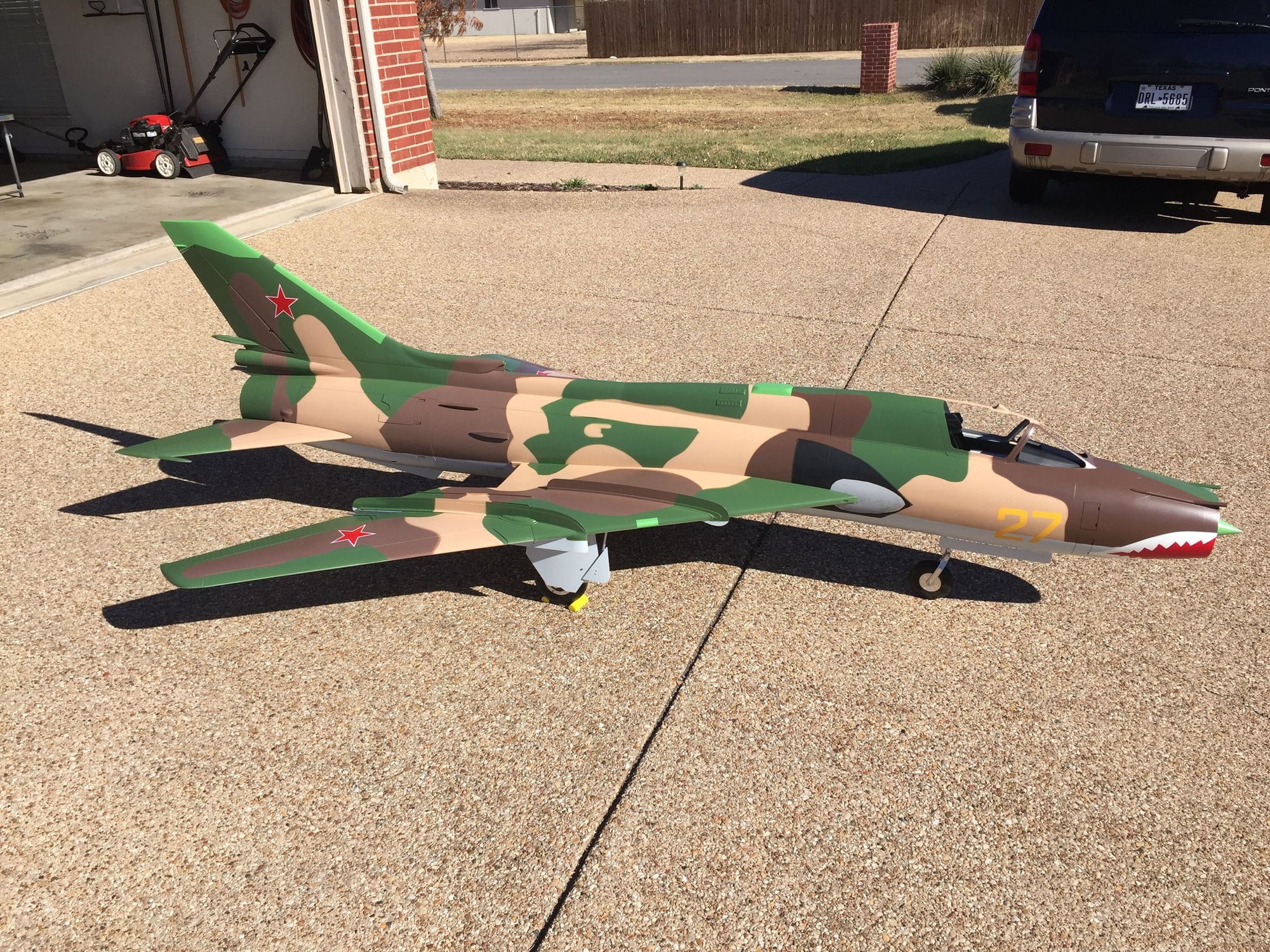
Wings Aft.
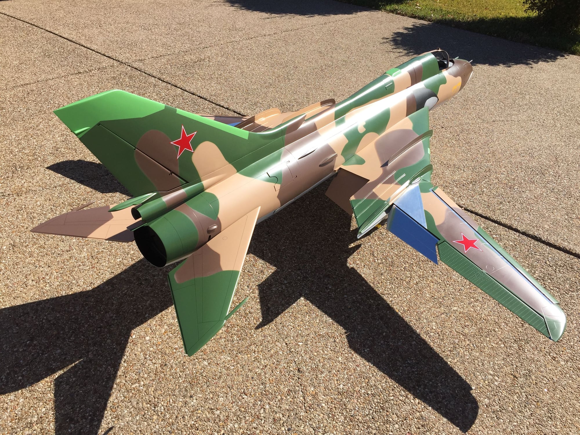
Wings Fwd with wing goodies deployed.
It better be better than this year.Per Pat's request here are a couple pics of my Fitter project. I was pretty convinced I was not going to get it in the air during this Winter season (like now) due to oncoming crappy weather, so I decided to move on with paint (about 1 month ago). Then, I would start on all the servo installs, control surface throws, landing gear tweaks, final wing pivot stuff, etc during the yukky weather.
Paul's Buccaneer is much closer to flying than the Fitter. Hopefully when the weather clears early next year, Fitter will be ready to fly. I also have not been flying turbines much for the last few months, so I'll want to get myself back to flying turbines before the Fitter goes up.
Wings Aft.
Wings Fwd with wing goodies deployed.